
Numerical Investigation of the Flow Regime in the Vanes and the Torsional Self-Excited Vibration of Guide Vane in the Pump Mode of a Reversible Pump-Turbine

Abstract
:1. Introduction
2. Numerical Method
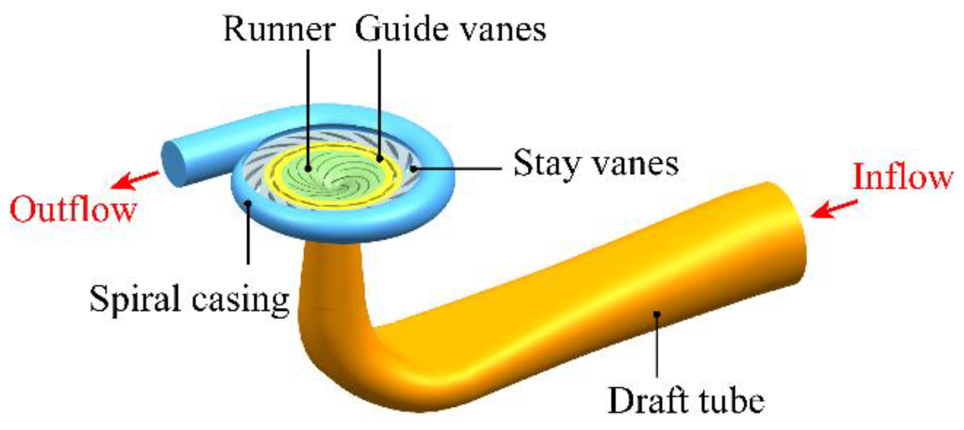
2.1. Pump-Turbine Unit and Computational Domains
2.2. Governing Equations and Numerical Settings
2.3. Independence Test of Mesh Density
3. Results and Discussion
3.1. Simulated Conditions
3.2. Inter-Vane Flow at Different Opening Angles
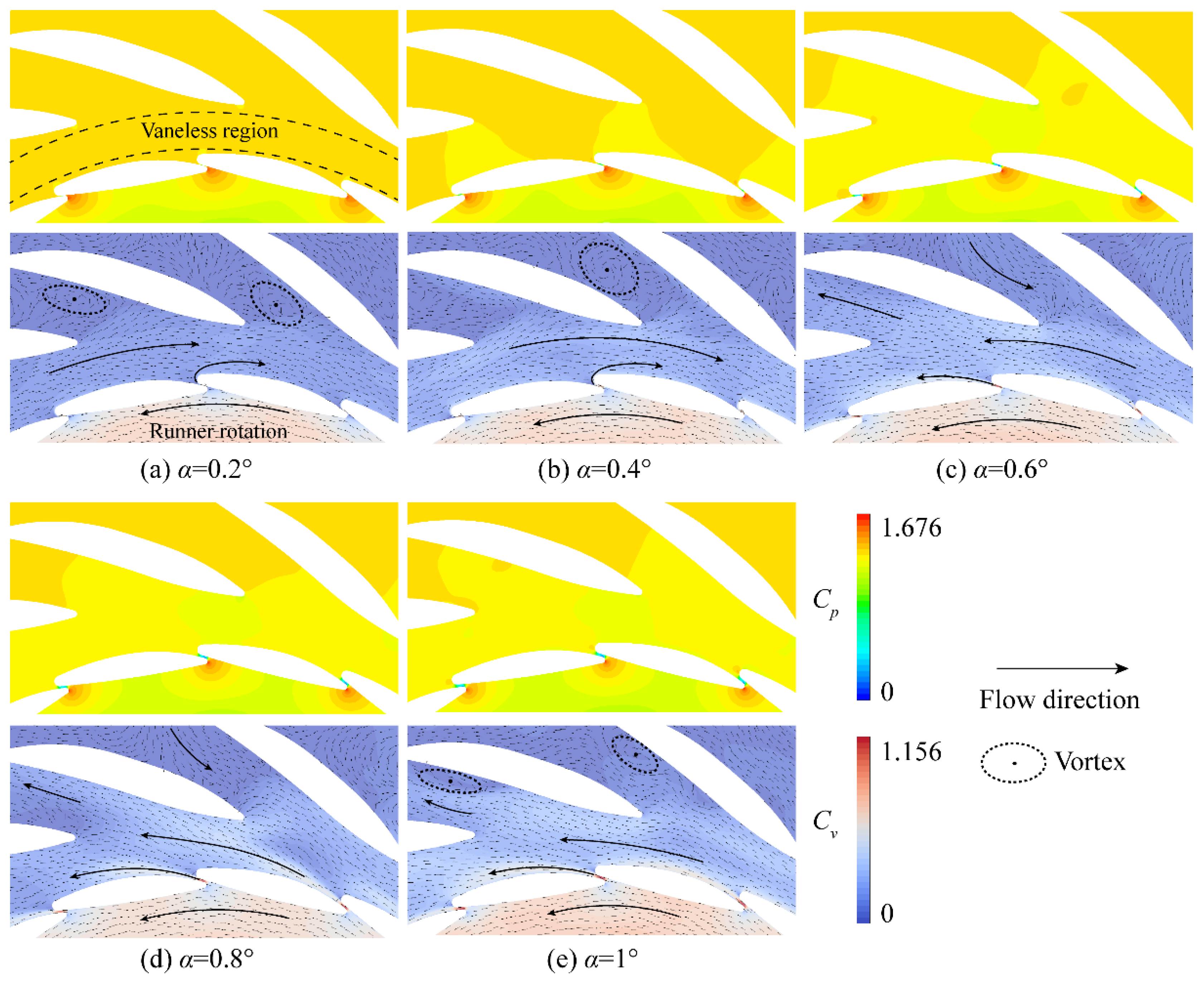
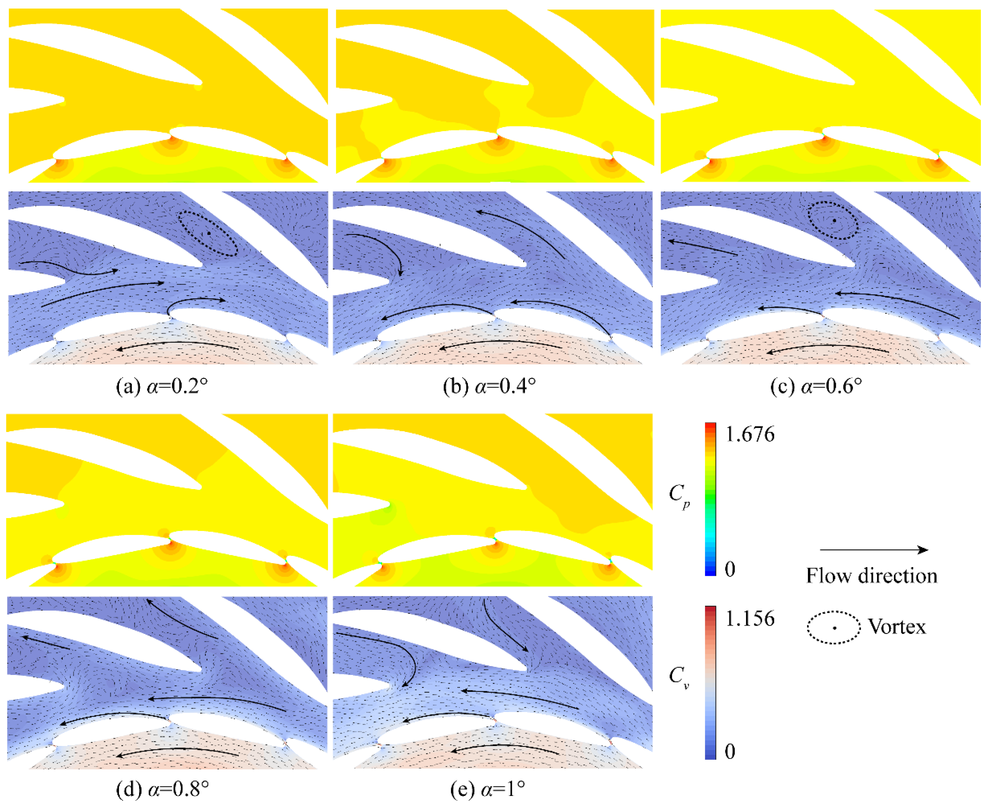
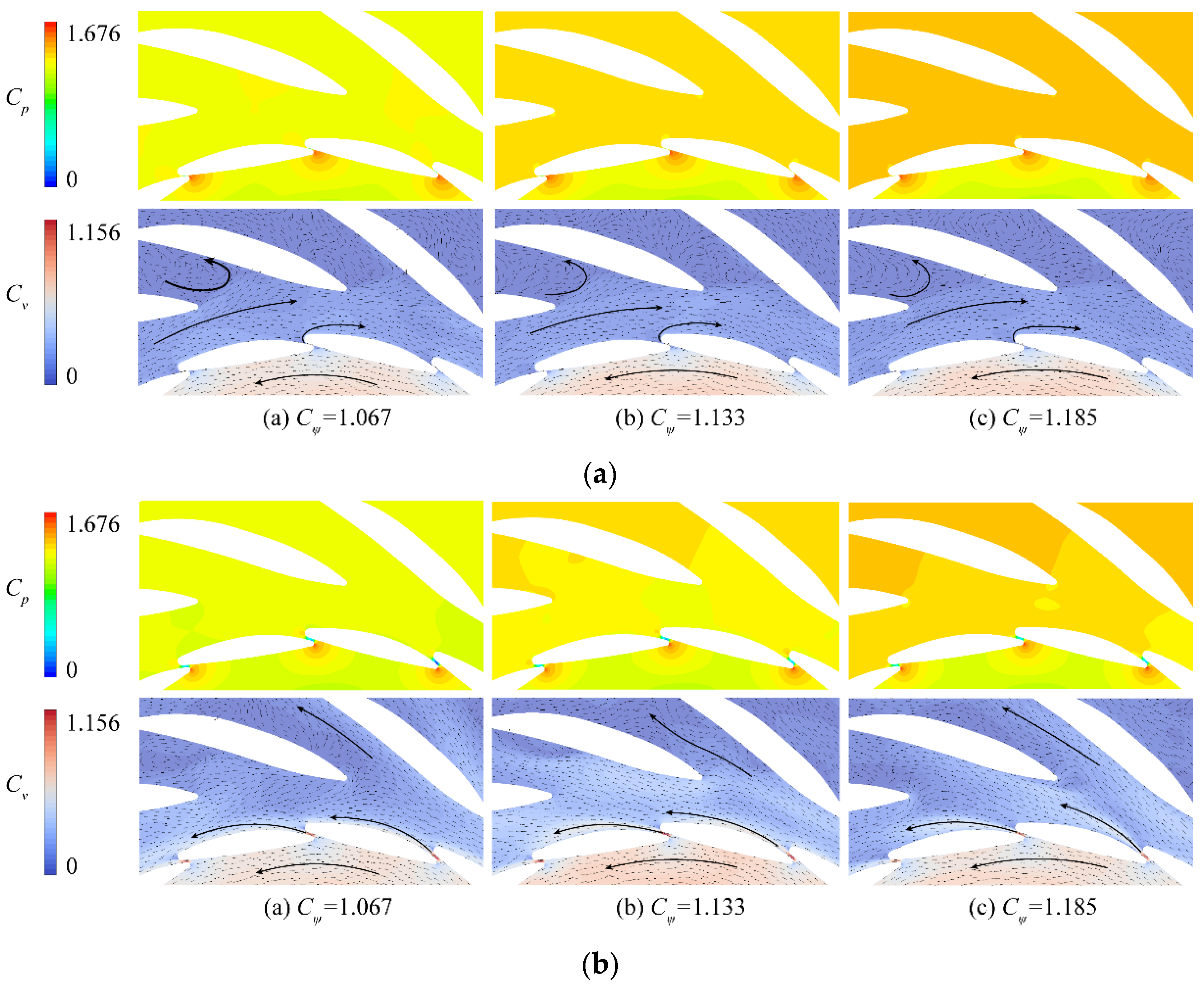
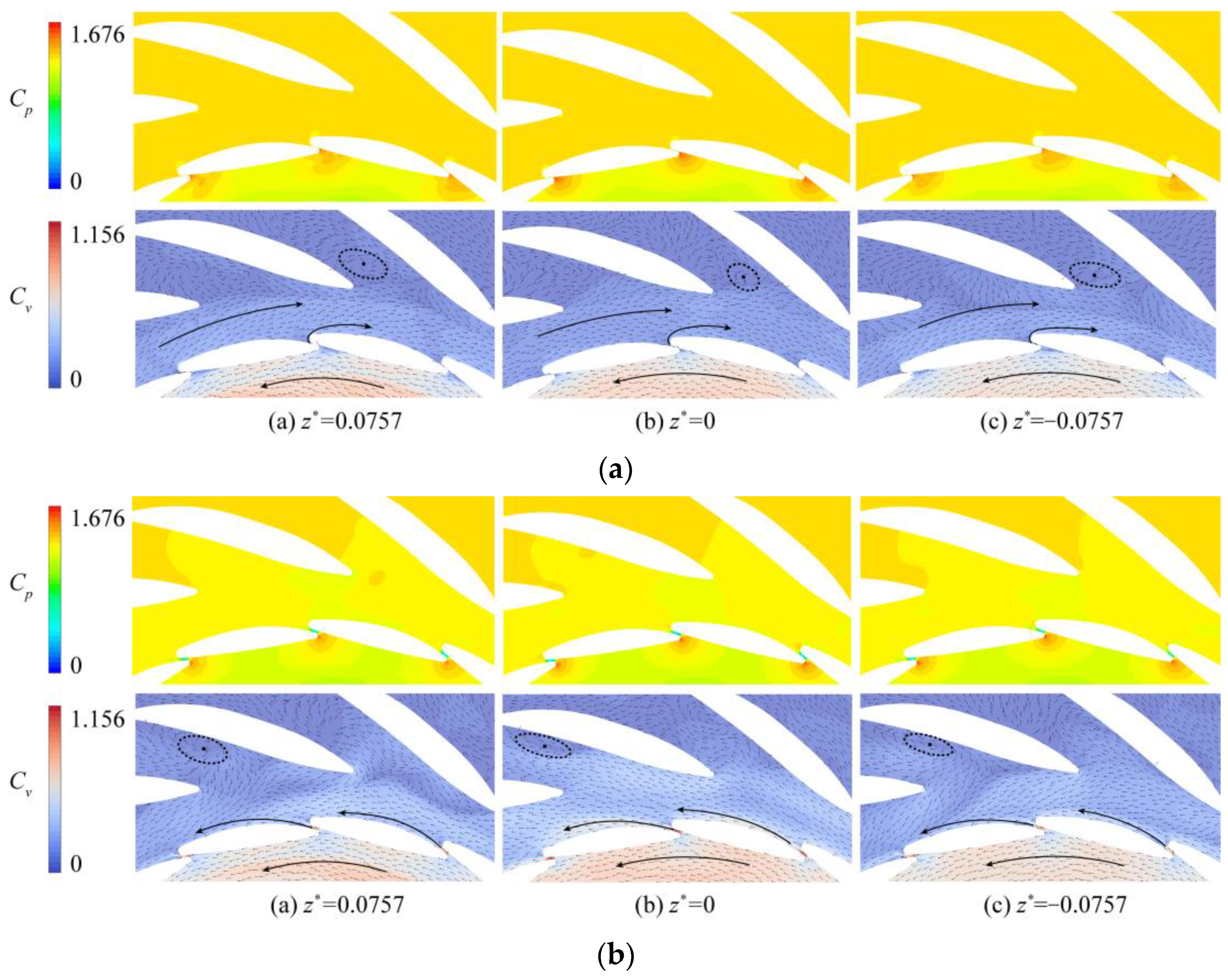
- The flow inside the GVs posed a high circumferential velocity component in the counterclockwise direction, which is consistent with the runner rotating direction. A local high-pressure region was formed at the leading edge of GV, which led to the high-speed flow through the inter-vane opening. This also caused a large drop in static pressure at the inter-vane opening.
- Two flow types were presented in the vaneless region between the GV blades and the stay vane blades. A flow circle rotating reversely against the runner rotation was formed in the vaneless region at a smaller opening angle, as shown in Figure 12a,b or Figure 13a. In this situation, the flow, passing through the inter-vane opening, attached to the trailing edge and merged into the counterclockwise flow circle. At larger opening angles, the jet flow through the inter-vane opening attached to the blade surface of the next GV. The flow in the vaneless region rotated in the same direction as the runner rotation.
3.3. Inter-Vane Flow at Different Head Coefficients
3.4. Inter-Vane Flow on Different Section Planes
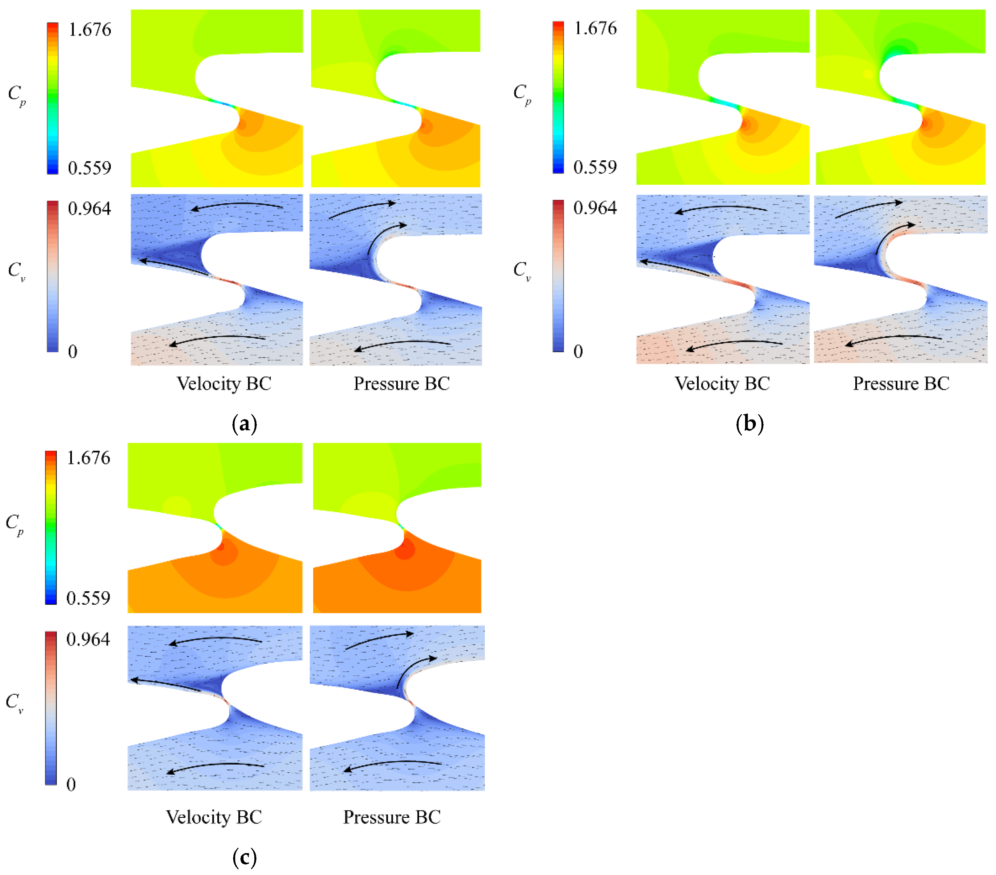
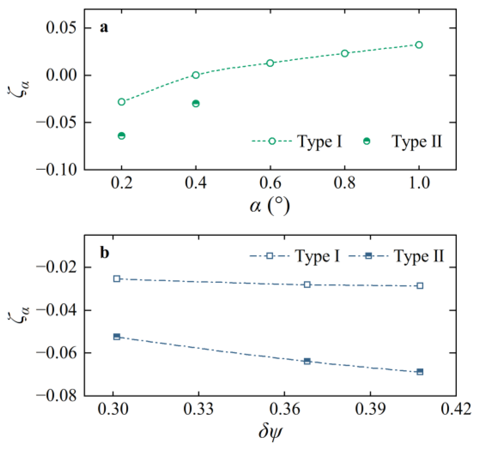
3.5. Influence of Flow Type in the Vanes on GV Self-Excited Vibration
- In the situation of velocity BC, the jet flow through the inter-vane opening attached to the blade surface of the next GV, and was similar to the 3D CFD results at larger opening ranges.
- In the situation of pressure BC, the flow attached to the trailing edge after passing through the inter-vane opening and then merged into the clockwise flow circle at the outside of GV.
- Under pressure BC, the static pressure at the leading edge was larger while the flow rate through the inter-vane opening was lower than that under velocity BC.
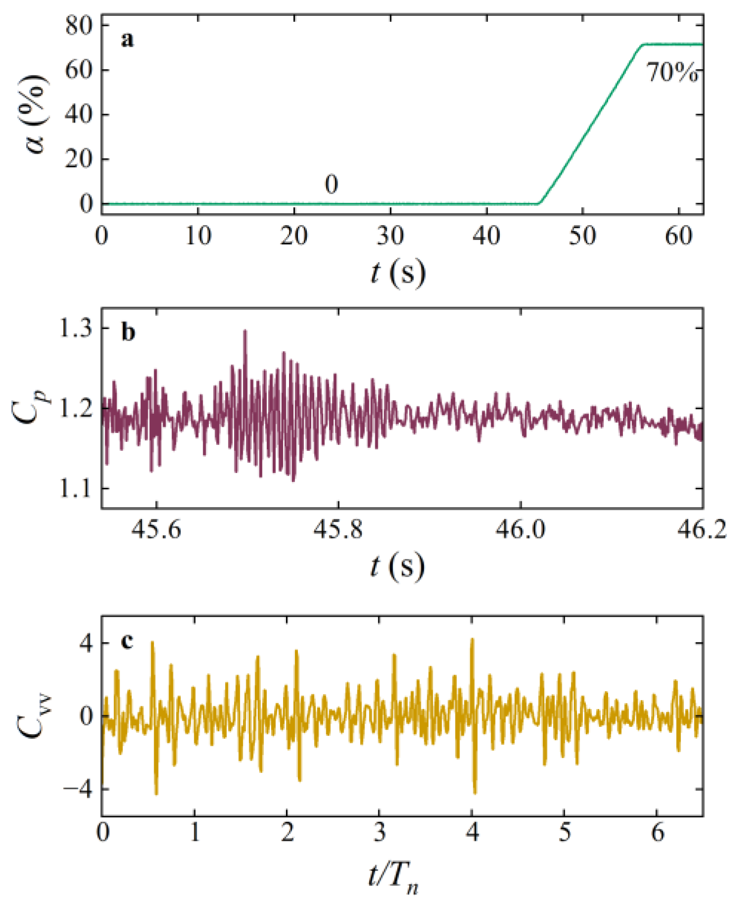
3.6. Torsional Vibration of Guide Vane in Site Tests and Verification of URANS-1DOF Coupling Simulation
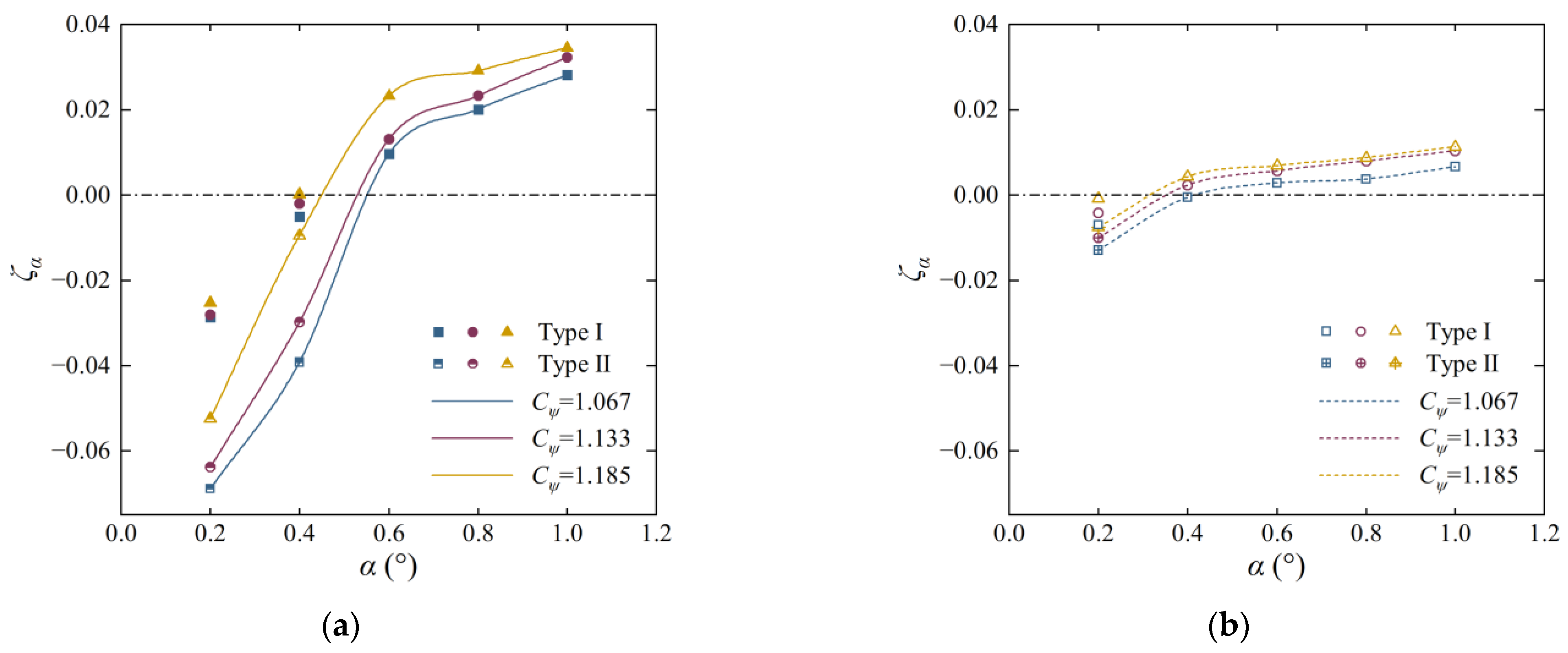
3.7. Analysis of the Torsional Vibration Stability for Two GVs with Different Airfoil Shapes
4. Conclusions
Author Contributions
Funding
Data Availability Statement
Acknowledgments
Conflicts of Interest
References
- Tagare, D. Electricity Power Generation: The Changing Dimensions; John Wiley & Sons, Inc.: Hoboken, NJ, USA, 2011. [Google Scholar]
- Rau, N. The State of Energy Storage in Electric Utility Systems and Its Effect on Renewable Energy Resources; No. NREL/TP-462-5337; National Renewable Energy Lab.: Golden, CO, USA, 1994. [Google Scholar]
- Zeng, W.; Yang, J.; Hu, J.; Yang, J. Guide-vane closing schemes for pump-turbines based on transient characteristics in S-shaped region. J. Fluid Eng. 2016, 138, 051302. [Google Scholar] [CrossRef]
- Li, D.; Wang, H.; Qin, Y.; Wei, X.; Qin, D. Numerical simulation of hysteresis characteristic in the hump region of a pump-turbine model. Renew. Energy 2018, 115, 433–447. [Google Scholar] [CrossRef]
- Oishi, A.; Yokoyama, T. Development of high-head single-and double-stage reversible pump-turbines. In Proceedings of the 10th IAHR Symposium on Hydraulic Machinery and Cavitation, Tokyo, Japan, 28 September–2 October 1980; pp. 441–452. [Google Scholar]
- Tanaka, H.; Tsunoda, S. The development of high head single stage pump-turbines. In Proceedings of the 10th IAHR Symposium on Hydraulic Machinery and Cavitation, Tokyo, Japan, 28 September–2 October 1980; pp. 429–440. [Google Scholar]
- Tao, R.; Zhou, X.; Xu, B.; Wang, Z. Numerical investigation of the flow regime and cavitation in the vanes of reversible pump-turbine during pump mode’s starting up. Renew. Energy 2019, 141, 9–19. [Google Scholar]
- Pacot, O.; Kato, C.; Guo, Y.; Yamade, Y.; Avellan, F. Large eddy simulation of the rotating stall in a pump-turbine operated in pumping mode at a part-load condition. J. Fluid Eng. 2016, 138, 111102. [Google Scholar] [CrossRef]
- Hasmatuchi, V.; Farhat, M.; Roth, S.; Botero, F.; Avellan, F. Experimental evidence of rotating stall in a pump-turbine at off-design conditions in generating mode. J. Fluid Eng. 2011, 133, 051104. [Google Scholar] [CrossRef]
- Nennemann, B.; Parkinson, E. YiXing pump turbine guide vane vibrations: Problem resolution with advanced CFD analysis. IOP Conf. Ser. Earth Environ. Sci. 2010, 12, 012057. [Google Scholar] [CrossRef] [Green Version]
- Potashnik, S. Some problems in operation of the Kiev pumped-storage station. Hydrotech. Constr. 1978, 12, 658–663. [Google Scholar] [CrossRef]
- Pulpitel, L. Self-excited vibration of pump turbine guide vanes. In Proceedings of the IAHR 11th Symposium on Hydraulic Machinery, Equipment and Cavitation, Amsterdam, The Netherlands, 13–17 September 1982. [Google Scholar]
- Zuo, Z.; Liu, S.; Sun, Y.; Wu, Y. Pressure fluctuations in the vaneless space of High-head pump-turbines—A review. Renew. Sustain. Energy Rev. 2015, 41, 965–974. [Google Scholar] [CrossRef]
- Zuo, Z.; Liu, S. Flow-induced instabilities in pump-turbines in China. Engineering 2017, 3, 504–511. [Google Scholar] [CrossRef]
- Kong, L. Analysis of abnormal sounds in working condition change-over for high-head pump-turbine. Mech. Electr. Tech. Hydropower Stn. 2004, 27, 12–14. [Google Scholar]
- Cai, J.; Zhou, X.; Deng, L.; Zhang, W. The research of the abnormal water hammer phenomenon based on the unit 3 over speed test of Jiangsu Yixing pumped storage power station. Water Power 2009, 35, 76–79. [Google Scholar]
- Bearman, P.; Wadcock, A. The interaction between a pair of circular cylinders normal to a stream. J. Fluid Mech. 1973, 61, 499–511. [Google Scholar] [CrossRef]
- Sumner, D.; Wong, S.; Price, S.; Paidoussis, M. Fluid behaviour of side-by-side circular cylinders in steady cross-flow. J. Fluid Struct. 1999, 13, 309–338. [Google Scholar] [CrossRef]
- Wang, Z.; Zhou, Y. Vortex interactions in a two side-by-side cylinder near-wake. Int. J. Heat Fluid Fl. 2005, 26, 362–377. [Google Scholar] [CrossRef]
- Ji, Q.; Wu, G.; Liao, W.; Fan, H. Flow deflection between guide vans in a pump turbine operating in pump mode with a slight opening. Energies 2022, 15, 1548. [Google Scholar] [CrossRef]
- Münch, C.; Ausoni, P.; Braun, O.; Farhat, M.; Avellan, F. Hydro Elastic Behavior of Vibrating Blades. In Proceedings of the 24th Symposium on Hydraulic Machinery and Systems, Foz do Iguassu, Brazil, 27–31 October 2008. [Google Scholar]
- Münch, C.; Ausoni, P.; Braun, O.; Farhat, M.; Avellan, F. Fluid–structure coupling for an oscillating hydrofoil. J. Fluids Struct. 2010, 26, 1018–1033. [Google Scholar] [CrossRef]
- Nennemann, B.; Sallaberger, M.; Henggeler, U.; Gentner, C.; Parkinson, E. Assessment of guide vane self-excitation stability at small openings in pump flow. IOP Conf. Ser. Earth Environ. Sci. 2012, 15, 062032. [Google Scholar] [CrossRef] [Green Version]
- Liang, Q.; Kang, W.; Zhou, L.; Wang, Z. Influence of End Wall Clearance on Guide Vane Self-Excited Vibrations at Small Openings during Pump Mode’s Starting Up Process of a Reversible Pump Turbine. J. Mar. Sci. Eng. 2022, 10, 528. [Google Scholar] [CrossRef]
- Menter, F. Two-equation eddy-viscosity turbulence models for engineering applications. Aiaa J. 1994, 32, 1598–1605. [Google Scholar] [CrossRef] [Green Version]
- Wilcox, D. Reassessment of the scale-determining equation for advanced turbulence models. Aiaa J. 1988, 26, 1299–1310. [Google Scholar] [CrossRef]
- Launder, B.; Sharma, B. Application of the energy-dissipation model of turbulence to the calculation of flow near a spinning disc. Lett. Heat Mass Transfer. 1974, 1, 131–137. [Google Scholar] [CrossRef]
- Trivedi, C. Investigation of compressible turbulent flow in a high-head Francis turbine. J. Fluid Eng. 2018, 140, 011101. [Google Scholar] [CrossRef]
- ANSYS. ANSYS CFX-Solver Modeling Guide: Release 18.0; Ansys Inc.: Canonsburg, PA, USA, 2017. [Google Scholar]
- Celik, I.; Ghia, U.; Roache, P.; Freitas, C. Procedure for estimation and reporting of uncertainty due to discretization in CFD applications. J. Fluid Eng. 2008, 130, 078001. [Google Scholar] [CrossRef]
- Kang, W.; Liang, Q.; Zhou, L.; Wang, Z. Numerical investigation on torsional self-excited vibration of guidevane in a reversible pump-turbine during pump mode’s starting up. J. Appl. Fluid Mech. 2022, 15, 1789–1799. [Google Scholar]


| Parameter | Value |
|---|---|
| Maximum head coefficient in pump mode, Cψmax | 1.185 |
| Minimum head coefficient in pump mode, Cψmin | 1.067 |
| BEP Flow Rate Coefficient at maximum head, Cφ-ψmax | 0.0302 |
| BEP Flow Rate Coefficient at minimum head, Cφ-ψmin | 0.0380 |
| Design rotation speed, nd | 500 [rpm] |
| Runner blade number, Zrn | 10 |
| GV blade number, Zgv | 16 |
| Stay vane blade number, Zsv | 16 |
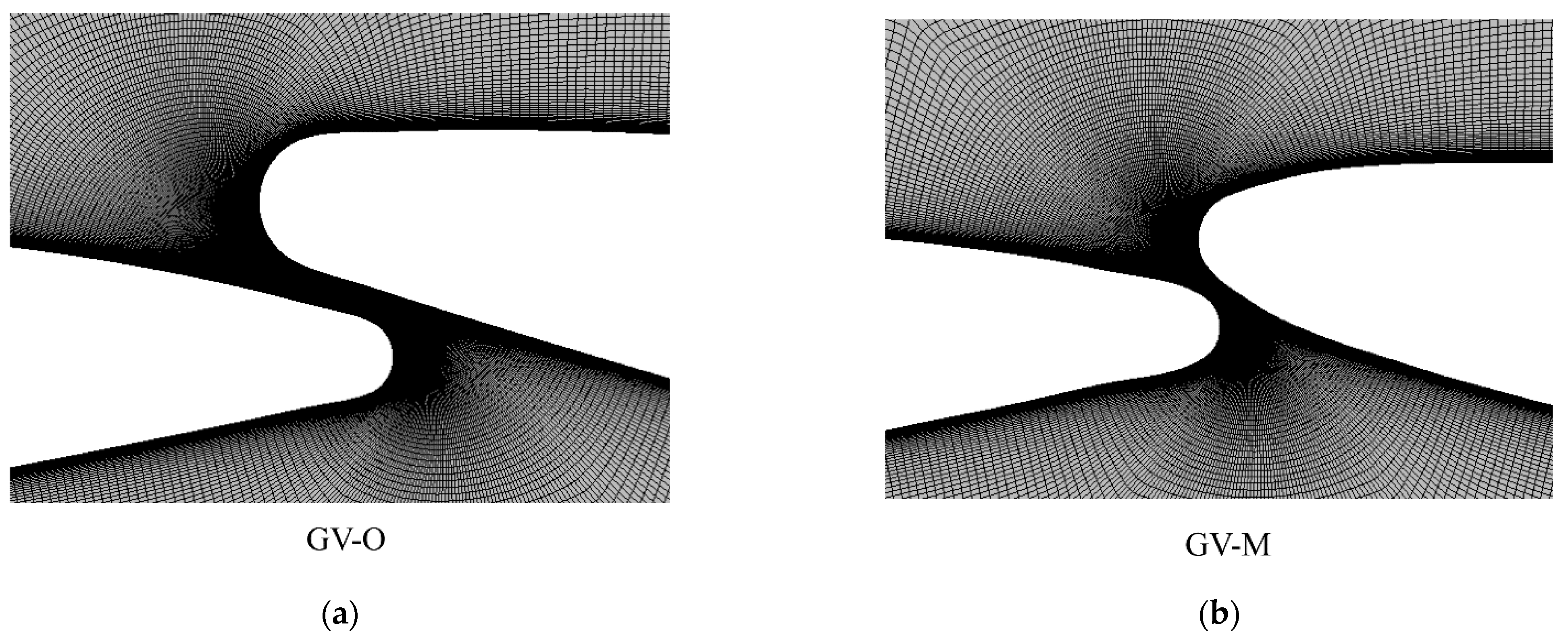
| Item | GV-O | GV-M |
|---|---|---|
| Radius of leading edge, RLE | RLE-O | 1.077 RLE-O |
| Arc radius, RH1 | 58.332 RLE-O | 51.471 RLE-O |
| Arc radius, RH2 | 89.713 RLE-O | 66.733 RLE-O |
| Arc radius, RH3 | - | 12.979 RLE-O |
| Radius of trailing edge, RTE | 1.714 RLE-O | 1.268 RLE-O |
| Arc radius, RL1 | 366.767 RLE-O | 788.317 RLE-O |
| Arc radius, RL2 | - | 66.004 RLE-O |
| Arc radius, RL3 | - | 9.027 RLE-O |
| Lever arm length, lLE | 22.809 RLE-O | 22.551 RLE-O |
| Lever arm length, lTE | 27.952 RLE-O | 25.335 RLE-O |
| Length of chord, lchord | 50.554 RLE-O | 47.738 RLE-O |
| Item | Value in 3D Case | Value in 2D Case |
|---|---|---|
| N1, N2, N3 | 1,224,227, 2,748,168, 6,136,583 | 22,892, 47,900, 101,030 |
| r21 | 1.307 | 1.452 |
| r32 | 1.309 | 1.446 |
| χ1 | 1.0408 | −0.0639 |
| χ2 | 0.8353 | −0.0679 |
| χ3 | 0.7925 | −0.0699 |
| χext21 | 1.0940 | −0.0596 |
| eext21 | 4.86% | 7.15% |
| GCIfine21 | 6.380% | 8.336% |
| GV Opening Angles | GV-O | GV-M | ||
|---|---|---|---|---|
| Type Ⅰ | Type Ⅱ | Type Ⅰ | Type Ⅱ | |
| 0.2 deg | −0.0281 | −0.0639 | −0.0042 | −0.0101 |
| 0.4 deg | 0.0002 | −0.0299 | - | - |
Publisher’s Note: MDPI stays neutral with regard to jurisdictional claims in published maps and institutional affiliations. |
© 2022 by the authors. Licensee MDPI, Basel, Switzerland. This article is an open access article distributed under the terms and conditions of the Creative Commons Attribution (CC BY) license (https://creativecommons.org/licenses/by/4.0/).
Share and Cite
Liang, Q.; Kang, W.; Zhou, L.; Wang, Z. Numerical Investigation of the Flow Regime in the Vanes and the Torsional Self-Excited Vibration of Guide Vane in the Pump Mode of a Reversible Pump-Turbine. Processes 2022, 10, 2314. https://doi.org/10.3390/pr10112314
Liang Q, Kang W, Zhou L, Wang Z. Numerical Investigation of the Flow Regime in the Vanes and the Torsional Self-Excited Vibration of Guide Vane in the Pump Mode of a Reversible Pump-Turbine. Processes. 2022; 10(11):2314. https://doi.org/10.3390/pr10112314
Chicago/Turabian StyleLiang, Quanwei, Wenzhe Kang, Lingjiu Zhou, and Zhengwei Wang. 2022. "Numerical Investigation of the Flow Regime in the Vanes and the Torsional Self-Excited Vibration of Guide Vane in the Pump Mode of a Reversible Pump-Turbine" Processes 10, no. 11: 2314. https://doi.org/10.3390/pr10112314