
Comparison of the New Refrigerant R1336mzz(E) with R1234ze(E) as an Alternative to R134a for Use in Heat Pumps


Abstract
:1. Introduction
2. Materials and Methods
- geothermal water up to a temperature of 55 °C;
- heat from flue gases;
- low-temperature sources from industrial processes;
- excess heat from cooling systems;
- heat of groundwater, lakes, seawater or rivers.
2.1. Refrigerants
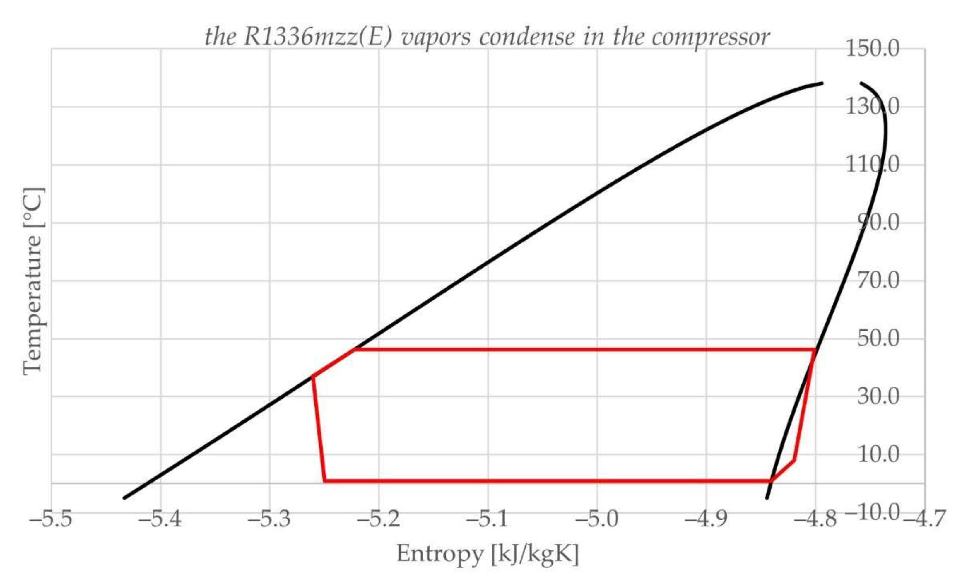
Temperature–Entropy (Further T–S) Diagrams for Different Refrigerants
2.2. Simulation of Heat Pump Operation
2.2.1. Compressor
2.2.2. Condenser
2.2.3. Expansion Valve
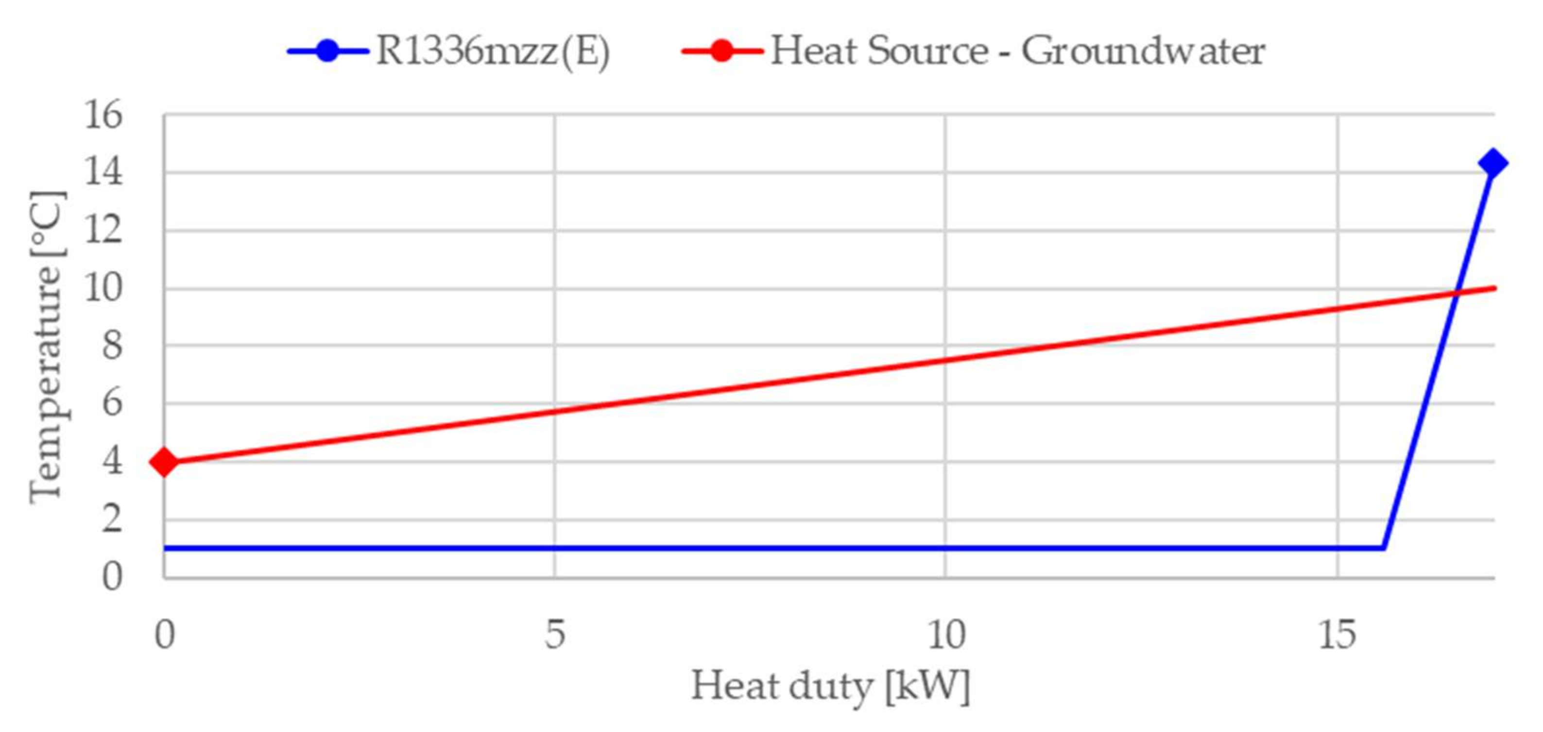
2.2.4. Evaporator
2.2.5. Heat Pump with Internal Heat Exchanger (Further IHE)
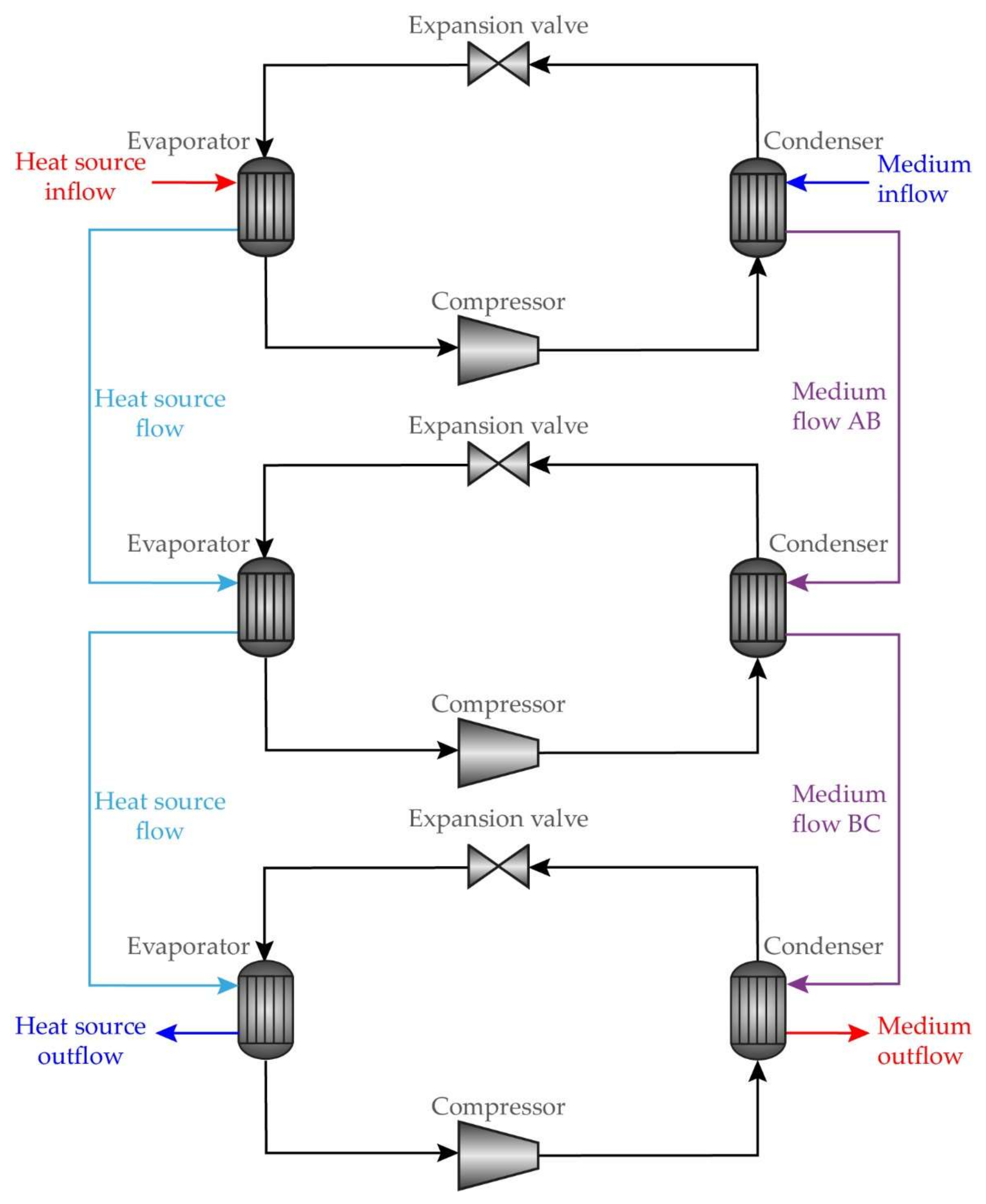
2.3. Simulation of a Series of Heat Pumps
3. Results and Discussion
3.1. Problems with the Use of R1336mzz(E) in a Basic Heat Pump
3.2. Use of R1336mzz(E) in a Heat Pump with an IHE
4. Conclusions
Author Contributions
Funding
Institutional Review Board Statement
Informed Consent Statement
Data Availability Statement
Conflicts of Interest
Nomenclature
| Symbols | |
| COP | coefficient of performance (/) |
| pCOMP,i | absolute discharge pressure of the compressor of the i heat pump in series (bar) |
| pEV,i | absolute outlet pressure of the expansion valve of the i heat pump in series (bar) |
| qmHW | mass flow of the heated medium through the system (kg/h) |
| qmR,i | mass flow of the refrigerant through the i heat pump in series (kg/h) |
| qmR | sum of mass flows of the refrigerant through all heat pumps in series (kg/h) |
| qmS,i | mass flow of the heat source through the evaporator of the i heat pump in series (kg/h) |
| qmS | sum of mass flows of the heat source through evaporators of all heat pumps in series (kg/h) |
| QCOND,i | heat duty of the condenser of the i heat pump in series (kW) |
| QEVAP,i | heat duty of the evaporator of the i heat pump in series (kW) |
| S | entropy (kJ/kgK) |
| T1,i | temperature of the flow from the evaporator to the compressor in the i heat pump in series (°C) |
| T1,A,MIN | minimum vapor inlet temperature into the compressor (°C) |
| T2,i | temperature of the flow from the compressor to the condenser in the i heat pump in series (°C) |
| T3,i | temperature of the flow from the condenser to the expansion valve in the i heat pump in series (°C) |
| T4,i | temperature of the flow from the expansion valve to the evaporator in the first heat pump in series (°C) |
| THW,AB | temperature of the flow of the heated medium from the condenser of the first heat pump in series to the condenser of the second heat pump in series (°C) |
| THW,BC | temperature of the flow of the heated medium from the condenser of the second heat pump in series to the condenser of the third heat pump in series (°C) |
| THW,IN | temperature of the inflow of the heated medium into the condenser of the first heat pump in series (°C) |
| THW,OUT | temperature of the outflow of the heated medium from the condenser of the third heat pump in series (°C) |
| TS,IN,i | temperature of the inflow of the heat source into the evaporator of the i heat pump in series (°C) |
| TS,OUT,i | temperature of the outflow of the heat source from the evaporator of the i heat pump in series (°C) |
| Wactual | work of the real compression process (kW) |
| WCOMP,i | work of the compressor of the first heat pump in series (kW) |
| Wisen | work of the isentropic compression process (kW) |
| Substract i in symbols | |
| A | the first heat pump in series |
| B | the second heat pump in series |
| C | the third heat pump in series |
| Greek Symbols | |
| ηisen | compressor efficiency |
| Abbreviations | |
| ASHRAE | The American Society of Heating, Refrigerating and Air-Conditioning Engineers |
| CFC | chlorofluorocarbons |
| COP | coefficient of performance |
| GHG | greenhouse gas |
| GWP | global warming potential |
| HCFC | hydrochlorofluorocarbons |
| HFC | hydrofluorocarbons |
| HFO | hydrofluoroolefins |
| HP | heat pump |
| IHE | internal heat exchanger |
| NBP | normal boiling point |
| ODP | ozone depletion potential |
| IUPAC Names of Refrigerants | |
| R1234yf | 2,3,3,3-tetrafluoroproene |
| R1234ze(E) | trans-1,3,3,3-tetrafluoropropene |
| R1336mzz(E) | trans-1,1,1,4,4,4-hexafluoro-2-butene |
| R134a | 1,1,1,2-tetrafluoroethane |
| R152a | 1,1-difluoroethane |
| R450A | mixture of R1234ze(E) and R134a |
| R515B | mixture of R1234ze(E) and R227ea |
Appendix A

| R134a | HP | HP with Connected CONDENSERS | pEV HP with Connected CONDENSERS and EVAPORATORS |
| qmR,A (kg/h) | 500 | 282 | 287 |
| qmR,B (kg/h) | 248 | 252 | |
| qmR (kg/h) | 500 | 530 | 539 |
| qmS,IN,A (kg/h) | 2835 | 1470 | 2800 |
| qmS,IN,B (kg/h) | 1130 | ||
| qmS,IN (kg/h) | 2835 | 2600 | 2800 |
| qmHW,IN (kg/h) | 1090 | 1089 | 1090 |
| T1,A (°C) | 8 | 8 | 8 |
| T2,A (°C) | 72.09 | 63.71 | 60.83 |
| T3,A (°C) | 37.02 | 37.07 | 37.15 |
| T4,A (°C) | 1 | 1 | 3.46 |
| T1,B (°C) | 8 | 4.51 | |
| T2,B (°C) | 73.06 | 69.89 | |
| T3,B (°C) | 48.84 | 48.36 | |
| T4,B (°C) | 1 | 1 | |
| TS,IN,A (°C) | 10 | 10 | 10 |
| TS,OUT,A (°C) | 3.97 | 3.45 | 6.51 |
| TS,IN,B (°C) | 10 | 6.51 | |
| TS,OUT,B (°C) | 3.41 | 3.86 | |
| THW,IN (°C) | 35 | 35 | 35 |
| THW,AB (°C) | 46 | 46 | |
| THW,OUT (°C) | 55 | 55 | 55 |
| pCOMP,A (bar) | 14.3 | 11.9 | 12 |
| pEV,A (bar) | 3.025 | 3.025 | 3.302 |
| pCOMP,B (bar) | 14.6 | 14.7 | |
| pEV,B (bar) | 3.025 | 3.025 | |
| QEVAP,A (kW) | 21.538 | 12.134 | 12.302 |
| QEVAP,B (kW) | 9.378 | 9.382 | |
| QEVAP (kW) | 21.538 | 21.512 | 21.684 |
| QCOND,A (kW) | 27.404 | 15.052 | 15.066 |
| QCOND,B (kW) | 12.326 | 12.338 | |
| QCOND (kW) | 27.404 | 27.378 | 27.404 |
| WCOMP,A (kW) | 6.175 | 3.072 | 2.909 |
| WCOMP,B (kW) | 3.102 | 3.111 | |
| WCOMP (kW) | 6.175 | 6.174 | 6.020 |
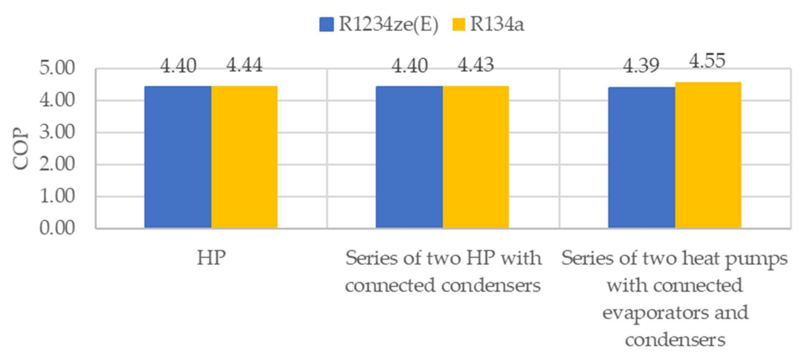
| COP | 4.44 | 4.43 | 4.55 |
| R1234ze(E) | HP | HP with connected CONDENSERS | pEV HP with connected CONDENSERS and EVAPORATORS |
| qmR,A (kg/h) | 500 | 282 | 285 |
| qmR,B (kg/h) | 248 | 250 | |
| qmR (kg/h) | 500 | 530 | 535 |
| qmS,IN,A (kg/h) | 2615 | 1470 | 3075 |
| qmS,IN,B (kg/h) | 1130 | ||
| qmS,IN (kg/h) | 2615 | 2600 | 3075 |
| qmHW,IN (kg/h) | 1007 | 1009 | 1090 |
| T1,A (°C) | 8 | 8 | 8 |
| T2,A (°C) | 64.89 | 57.93 | 57.28 |
| T3,A (°C) | 37.11 | 37.09 | 37.13 |
| T4,A (°C) | 1 | 1 | 4.02 |
| T1,B (°C) | 8 | 5.09 | |
| T2,B (°C) | 65.25 | 65.14 | |
| T3,B (°C) | 48.15 | 48.08 | |
| T4,B (°C) | 1 | 1 | |
| TS,IN,A (°C) | 10 | 10 | 10 |
| TS,OUT,A (°C) | 3.97 | 3.95 | 7.09 |
| TS,IN,B (°C) | 10 | 7.09 | |
| TS,OUT,B (°C) | 3.89 | 4.86 | |
| THW,IN (°C) | 35 | 35 | 35 |
| THW,AB (°C) | 46 | 46 | |
| THW,OUT (°C) | 55 | 55 | 55 |
| pCOMP,A (bar) | 11.3 | 9.3 | 10 |
| pEV,A (bar) | 2.206 | 2.206 | 2.462 |
| pCOMP,B (bar) | 11.2 | 12 | |
| pEV,B (bar) | 2.206 | 2.206 | |
| QEVAP,A (kW) | 19.852 | 11.196 | 11.277 |
| QEVAP,B (kW) | 8.696 | 8.601 | |
| QEVAP (kW) | 19.852 | 19.892 | 19.878 |
| QCOND,A (kW) | 25.317 | 13.950 | 13.947 |
| QCOND,B (kW) | 11.421 | 11.421 | |
| QCOND (kW) | 25.317 | 25.368 | 25.368 |
| WCOMP,A (kW) | 5.753 | 2.895 | 2.810 |
| WCOMP,B (kW) | 2.869 | 2.968 | |
| WCOMP (kW) | 5.753 | 5.764 | 5.778 |
| COP | 4.40 | 4.40 | 4.39 |
Appendix B
| R134a | HP | HP with Connected CONDENSERS | pEV HP with Connected CONDENSERS and EVAPORATORS |
| qmR,A (kg/h) | 500 | 212 | 213 |
| qmR,B (kg/h) | 189 | 194 | |
| qmR,C (kg/h) | 162 | 167 | |
| qmR (kg/h) | 500 | 563 | 574 |
| qmS,IN,A (kg/h) | 2515 | 1300 | 2820 |
| qmS,IN,B (kg/h) | 1000 | ||
| qmS,IN,C (kg/h) | 700 | ||
| qmS,IN (kg/h) | 2515 | 3000 | 2820 |
| qmHW,IN (kg/h) | 747 | 750 | 750 |
| T1,A (°C) | 8 | 8 | 8 |
| T2,A (°C) | 82.25 | 63.71 | 66.32 |
| T3,A (°C) | 37.13 | 37.14 | 37.51 |
| T4,A (°C) | 1 | 1 | 4.43 |
| T1,B (°C) | 8 | 5.44 | |
| T2,B (°C) | 75.26 | 71.13 | |
| T3,B (°C) | 49.16 | 49.22 | |
| T4,B (°C) | 1 | 2.47 | |
| T1,C (°C) | 8 | 3.42 | |
| T2,C (°C) | 84.68 | 80.21 | |
| T3,C (°C) | 59.12 | 59.13 | |
| T4,C (°C) | 1 | 1 | |
| TS,IN,A (°C) | 10 | 10 | 10 |
| TS,OUT,A (°C) | 3.2 | 4.43 | 7.44 |
| TS,IN,B (°C) | 10 | 7.44 | |
| TS,OUT,B (°C) | 4.35 | 5.42 | |
| TS,IN,C (°C) | 10 | 5.42 | |
| TS,OUT,C (°C) | 3.94 | 3.92 | |
| THW,IN (°C) | 35 | 35 | 35 |
| THW,AB (°C) | 47 | 47 | |
| THW,BC (°C) | 57 | 57 | |
| THW,OUT (°C) | 65 | 65 | 65 |
| pCOMP,A (bar) | 17.7 | 11.9 | 13.9 |
| pEV,A (bar) | 3.025 | 3.025 | 3.42 |
| pCOMP,B (bar) | 15.3 | 15.4 | |
| pEV,B (bar) | 3.025 | 3.187 | |
| pCOMP,C (bar) | 18.6 | 18.6 | |
| pEV,C (bar) | 3.025 | 3.025 | |
| QEVAP,A (kW) | 21.416 | 9.155 | 9.091 |
| QEVAP,B (kW) | 7.122 | 7.175 | |
| QEVAP,C (kW) | 5.343 | 5.329 | |
| QEVAP (kW) | 21.416 | 21.580 | 21.595 |
| QCOND,A (kW) | 28.190 | 11.309 | 11.309 |
| QCOND,B (kW) | 9.434 | 9.434 | |
| QCOND,C (kW) | 7.559 | 7.559 | |
| QCOND (kW) | 28.190 | 28.302 | 28.302 |
| WCOMP,A (kW) | 7.008 | 2.310 | 2.335 |
| WCOMP,B (kW) | 2.434 | 2.378 | |
| WCOMP,C (kW) | 2.333 | 2.348 | |
| WCOMP (kW) | 7.008 | 7.077 | 7.061 |
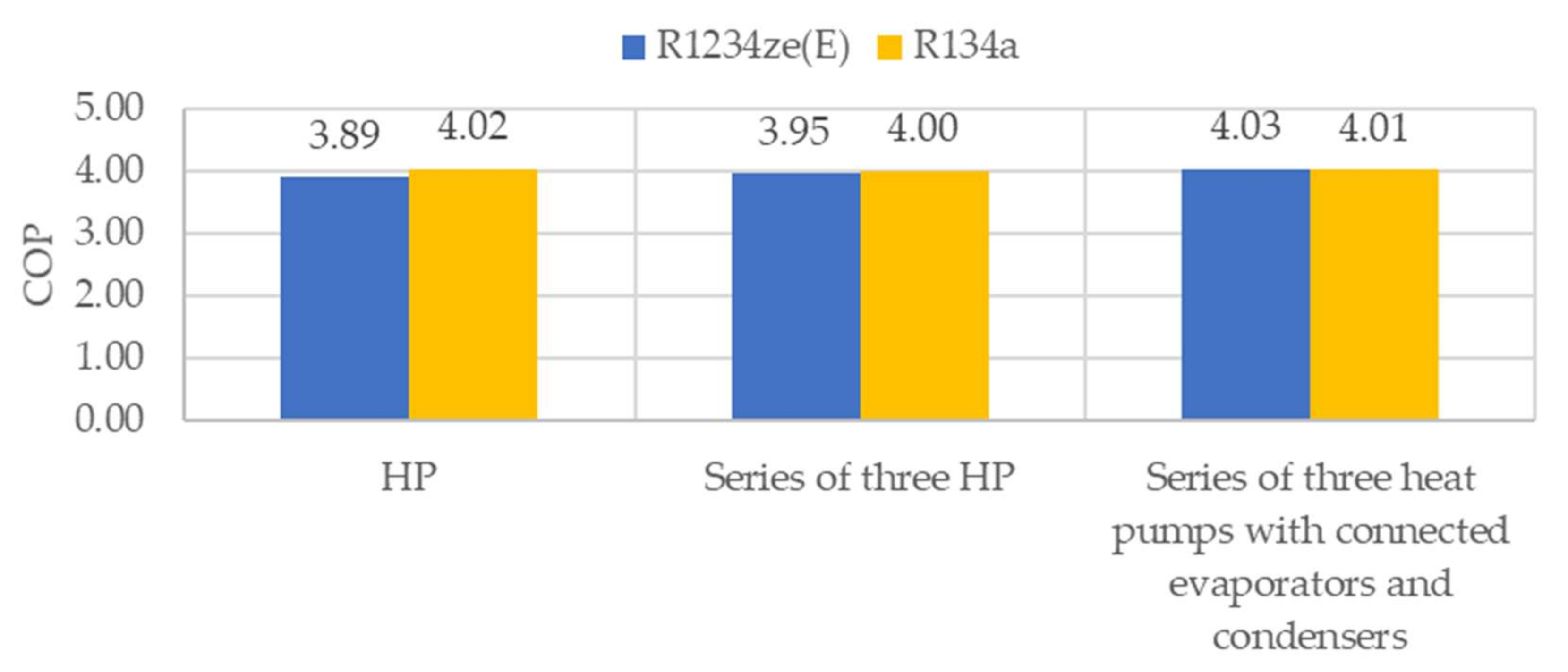
| COP | 4.02 | 4.00 | 4.01 |
| R1234ze(E) | HP | HP with connected CONDENSERS | pEV HP with connected CONDENSERS and EVAPORATORS |
| qmR,A (kg/h) | 500 | 212 | 215 |
| qmR,B (kg/h) | 191 | 193 | |
| qmR,C (kg/h) | 164 | 166 | |
| qmR (kg/h) | 500 | 567 | 574 |
| qmS,IN,A (kg/h) | 2615 | 1200 | 4249 |
| qmS,IN,B (kg/h) | 900 | ||
| qmS,IN,C (kg/h) | 650 | ||
| qmS,IN (kg/h) | 2615 | 2750 | 4249 |
| qmHW,IN (kg/h) | 697 | 697 | 693 |
| T1,A (°C) | 8 | 8 | 8 |
| T2,A (°C) | 77.18 | 58.75 | 56.68 |
| T3,A (°C) | 37.02 | 37.14 | 37.52 |
| T4,A (°C) | 1 | 1 | 4.55 |
| T1,B (°C) | 8 | 6.35 | |
| T2,B (°C) | 67.36 | 64.84 | |
| T3,B (°C) | 49.30 | 49.07 | |
| T4,B (°C) | 1 | 4.20 | |
| T1,C (°C) | 8 | 5.19 | |
| T2,C (°C) | 75.70 | 72.23 | |
| T3,C (°C) | 59.14 | 59.03 | |
| T4,C (°C) | 1 | 1 | |
| TS,IN,A (°C) | 10 | 10 | 10 |
| TS,OUT,A (°C) | 3.96 | 4.43 | 8.42 |
| TS,IN,B (°C) | 10 | 8.42 | |
| TS,OUT,B (°C) | 4.18 | 7.19 | |
| TS,IN,C (°C) | 10 | 7.19 | |
| TS,OUT,C (°C) | 3.95 | 6.27 | |
| THW,IN (°C) | 35 | 35 | 35 |
| THW,AB (°C) | 47 | 47 | |
| THW,BC (°C) | 57 | 57 | |
| THW,OUT (°C) | 65 | 65 | 65 |
| pCOMP,A (bar) | 14.9 | 9.5 | 10 |
| pEV,A (bar) | 2.026 | 2.026 | 2.51 |
| pCOMP,B (bar) | 11.8 | 12 | |
| pEV,B (bar) | 2.026 | 2.32 | |
| pCOMP,C (bar) | 14.4 | 14.5 | |
| pEV,C (bar) | 2.026 | 2.206 | |
| QEVAP,A (kW) | 19.883 | 8.412 | 8.468 |
| QEVAP,B (kW) | 6.603 | 6.591 | |
| QEVAP,C (kW) | 4.955 | 4.912 | |
| QEVAP (kW) | 19.883 | 19.970 | 19.971 |
| QCOND,A (kW) | 26.303 | 10.510 | 10.450 |
| QCOND,B (kW) | 8.768 | 8.717 | |
| QCOND,C (kW) | 7.052 | 6.985 | |
| QCOND (kW) | 26.303 | 26.303 | 26.152 |
| WCOMP,A (kW) | 6.758 | 2.208 | 2.086 |
| WCOMP,B (kW) | 2.278 | 2.223 | |
| WCOMP,C (kW) | 2.179 | 2.182 | |
| WCOMP (kW) | 6.758 | 6.665 | 6.491 |
| COP | 3.89 | 3.95 | 4.03 |
References
- Official Journal of the European Union. Directive (Eu) 2018/2002 of the European Parliament and of the Council of 11 December 2018 Amending Directive 2012/27/EU on Energy Efficiency. 2018. Available online: https://eur-lex.europa.eu/legal-content/EN/TXT/PDF/?uri=CELEX:32018L2002&rid=7 (accessed on 1 October 2021).
- Aprea, C.; Greco, A.; Maiorino, A.; Masselli, C.; Metallo, A. HFO1234ze as drop-in replacement for R134a in domestic refrigerators: An enviromental impact analysis. Energy Procedia 2016, 101, 964–971. [Google Scholar] [CrossRef]
- Mota-Babiloni, A.; Navarro-Esbri, J.; Moles, F.; Cervera, A.B.; Peris, B.; Verdu, G. A review od refrigerant R1234ze(E) recent investigations. Appl. Therm. Eng. 2016, 95, 211–222. [Google Scholar] [CrossRef]
- European Parliament. EUR-Lex. 16 April 2014. Available online: https://eur-lex.europa.eu/legal-content/EN/TXT/?uri=celex%3A32014R0517 (accessed on 28 November 2021).
- Pierantozzi, M.; Tomassetti, S.; di Nicola, G. Climate Change and Refrigerants: Thermodynamic Properties of Low-GWP Fluids for Domestic Applications and Binary Sytems for Low-Temperature Options. Appl. Sci. 2020, 10, 2014. [Google Scholar] [CrossRef] [Green Version]
- Cabello, R.; Sánchez, D.; Llopis, R.; Arauzo, I.; Torrella, E. Experimental comparison between R152a and R134a working in a refrigeration facility equipped with a hermetic compressor. Int. J. Refrig. 2015, 60, 92–105. [Google Scholar] [CrossRef] [Green Version]
- Mota-Babiloni, A.; Navarro-Esbri, J.; Barragan-Cervera, A.; Moles, F.; Peris, B. Experimental study of an R1234ze(E)/R134a mixture (R450a) as R134a replacement. Int. J. Refrig. 2015, 51, 52–58. [Google Scholar] [CrossRef]
- Mateu-Royo, C.; Mota-Babiloni, A.; Navarro-Esbrí, J.; Barragán-Cervera, Á. Comparative analysis of HFO-1234ze(E) and R-515B as low GWP alternatives to HFC-134a in moderately high temperature heat pumps. Int. J. Refrig. 2021, 124, 197–206. [Google Scholar] [CrossRef]
- Yataganbaba, A.; Kilicarslan, A.; Kurtbas, I. Exergy analysis of R1234yf and R1234ze(E) as R134a replacements in a two evaporator vapour compression refrigeration system. Int. J. Refrig. 2015, 60, 26–37. [Google Scholar] [CrossRef]
- Sakoda, N.; Higashi, Y.; Akasaka, R. Measurements of PvT Properties, Vapor Pressures, Saturated Densities, and Critical Parameters for trans-1,1,1,4,4,4-Hexafluoro-2-butene (R1336mzz(E)). J. Chem. Eng. Data 2020, 66, 734–739. [Google Scholar] [CrossRef]
- Juhasz, J.R. Novel Working Fluid, HFO-1336mzz(E), for Use in Waste Heat Recovery Application. In Proceedings of the 12th IEA Heat Pump Conference, Rotterdam, The Netherlands, 15–18 May 2017. [Google Scholar]
- 1,1,1,2-Tetrafluoroethane. Available online: https://en.wikipedia.org/wiki/1,1,1,2-Tetrafluoroethane (accessed on 4 July 2019).
- 1,3,3,3-Tetrafluoropropene. Available online: https://en.wikipedia.org/wiki/1,3,3,3-Tetrafluoropropene (accessed on 4 July 2019).
- (E)-1,1,1,4,4,4-Hexafluoro-2-Buten. Available online: https://de.wikipedia.org/wiki/(E)-1,1,1,4,4,4-Hexafluor-2-buten (accessed on 8 November 2021).
- United Nations Enviroment Programme and ASHRAE. Update on New Refrigerants Designations and Safety Classifications. 2020. Available online: https://www.ashrae.org/file%20library/professional%20development/ashrae-unep/factsheet_ashrae_english_september2020.pdf (accessed on 10 October 2021).
- Honeywell. Honeywell Refrigerant: The Enviromental Alternative to Traditional Refrigetants. Available online: https://www.honeywell-refrigerants.com/india/?document=solstice-ze-hfo-1234ze-brochure-2012&download=1 (accessed on 11 April 2019).
- Raabe, G. Molecular Simulation Studies on the Vapor-Liquid Equilibrium of the cis- and trans-HCFO-1233zd and the cis- and trans-HFO-1336mzz. J. Chem. Eng. Data 2015, 60, 2412–2419. [Google Scholar] [CrossRef]
- Morriesen, A.; Deschamps, C. Experimental investigation of transient fluid flow and superheating in the suction chamber of a refrigeration reciprocating compressor. Appl. Therm. Eng. 2012, 41, 61–70. [Google Scholar] [CrossRef]
- Yang, B.; Fang, X.; Zhang, L.; Zhuang, F.; Bi, M.; Chen, C.; Li, G.; Wang, X. Applicability of emipircal models of isentropic efficiency and mass flow rate of dynamic compressors to jet engines. Prog. Aerosp. Sci. 2019, 106, 32–43. [Google Scholar] [CrossRef]


| Refrigerant | R134a | R1234ze(E) | R1336mzz(E) |
|---|---|---|---|
| Chemical name | 1,1,1,2-tetrafluoroethane | trans-1,3,3,3-tetrafluoropropene | trans-1,1,1,4,4,4-hexafluoro-2-butene |
| Family | HFC | HFO | HFO |
| Structural formula | 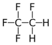 | 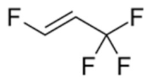 |  |
| Molecular weight (g/mol) | 102.03 | 114.04 | 164.05 |
| * NBP (°C) | −26.3 | −19.0 | 7.5 |
| Critical temperature (°C) | 101.1 | 109.4 | 137.7 |
| Critical pressure (MPa) | 4.06 | 3.63 | 3.15 |
| Atmospheric lifetime | 13 years | 18 days | Short |
| ASHRAE safety classification | A1 | A2L | A1 |
| Flammability | Non-flammable | Lower flammability | Non-flammable |
| Toxicity | Lower toxicity | Lower toxicity | Lower toxicity |
| ODP | 0 | 0 | 0 |
| GWP (kg CO2 eq/kg of refrigerant) | 1300 | 4 | 18 |
| Refrigerant | pEV,A (bar) |
|---|---|
| R134a | 3.025 |
| R1234ze(E) | 2.206 |
| R1336mzz(E) | 0.776 |
| Refrigerant | Temperature of the Heated Water | 45 °C | 55 °C | 65 °C |
|---|---|---|---|---|
| R1234ze(E) pEV,A = 2.21 bar | T1,A,MIN | 4 °C | 4.7 °C | 5.1 °C |
| pCOMP,A | 8.6 bar | 11.1 bar | 14.9 bar | |
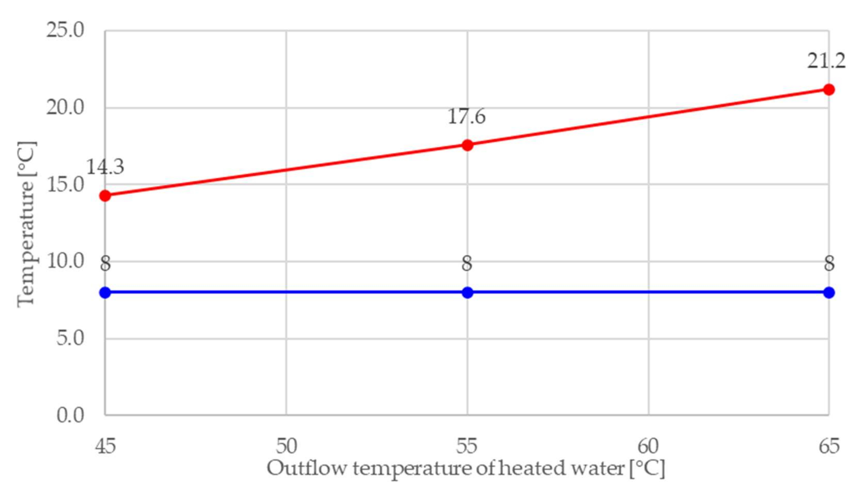
| R1336mzz(E) pEV,A = 0.78 bar | T1,A,MIN | 14.3 °C | 17.6 °C | 21.2 °C |
| pCOMP,A | 3.7 bar | 4.9 bar | 6.4 bar |
Publisher’s Note: MDPI stays neutral with regard to jurisdictional claims in published maps and institutional affiliations. |
© 2022 by the authors. Licensee MDPI, Basel, Switzerland. This article is an open access article distributed under the terms and conditions of the Creative Commons Attribution (CC BY) license (https://creativecommons.org/licenses/by/4.0/).
Share and Cite
Drofenik, J.; Urbancl, D.; Goričanec, D. Comparison of the New Refrigerant R1336mzz(E) with R1234ze(E) as an Alternative to R134a for Use in Heat Pumps. Processes 2022, 10, 218. https://doi.org/10.3390/pr10020218
Drofenik J, Urbancl D, Goričanec D. Comparison of the New Refrigerant R1336mzz(E) with R1234ze(E) as an Alternative to R134a for Use in Heat Pumps. Processes. 2022; 10(2):218. https://doi.org/10.3390/pr10020218
Chicago/Turabian StyleDrofenik, Jan, Danijela Urbancl, and Darko Goričanec. 2022. "Comparison of the New Refrigerant R1336mzz(E) with R1234ze(E) as an Alternative to R134a for Use in Heat Pumps" Processes 10, no. 2: 218. https://doi.org/10.3390/pr10020218