Article

Influence of Yield Pillar Width on Coal Mine Roadway Stability in Western China: A Case Study

1
State Key Laboratory of Mining Disaster Prevention and Control, Shandong University of Science and Technology, Qingdao 266590, China
2
Department of Mining and Materials Engineering, McGill University, Montreal, QC H3A 0E8, Canada
*
Author to whom correspondence should be addressed.
Processes 2022, 10(2), 251; https://doi.org/10.3390/pr10020251
Submission received: 1 December 2021 / Revised: 11 January 2022 / Accepted: 19 January 2022 / Published: 27 January 2022
(This article belongs to the Special Issue Numerical Modeling in Civil and Mining Geotechnical Engineering)

Abstract

:
Roadway excavation technology in underground coal mines has an important impact on mining efficiency and production safety. High-efficiency and rapid excavation of underground roadways in coal mines are important means to improve the production efficiency of coal mines. To tackle the problems of instability of roadway and support difficulties, the tail entry of panel 3105 in Mataihao Mine was used as the case study. The methods of underground investigation, theoretical analysis, and FLAC3D numerical simulation were used to analyze the stability of the surrounding rock under different yield pillar widths. Through the stress field, displacement field, and plastic zone of roadway surrounding rock, the stability of the rock surrounding the roadway under different yield pillar widths (4 m, 6 m, and 8 m) was analyzed. The results show that, with the increase in the yield pillar width, the plastic zone failure and displacement of the roadway surrounding rock are mainly manifested in the narrow pillar rib, seam rib, roof, and floor. The plastic zone distribution changes slightly; the roadway displacement exhibits basic symmetry. The vertical stress and the displacement of the two sides increase with the increase in the yield pillar width, and the roof displacement and the ratio of tensile failure of the surrounding rock decrease with the increase in the yield pillar width. According to the dynamic evolution law of the rock surrounding the roadway along the goaf side, the effect of the yield pillar size is revealed, and a reasonable yield pillar width is determined. When the yield pillar width is 6 m, the plastic zone failure of the surrounding rock and the displacement of the two sides of the roof are the most balanced among the three schemes. This provides a reference for the selection of the narrow yield pillar size in coal mines under the same geological conditions.

1. Introduction

Coal mining in western China has become the main production source of China in recent years thanks to the features of rich resource, shallow depth, and simple geology [1,2]. In the early coal exploration of western China, wide coal pillars (20–40 m in width) were commonly employed. However, in addition to the issue of recovery rate, the remaining wide pillars carry large amounts of overburden and stress, which lead to serious ground stability problems when mining the coal seams below the pillars [3]. Optimizing the pillar width will significantly improve the roadway stability by avoiding the unloading of concentrated pillar stress [4]. Therefore, studies on the goaf-side entry technique and other panel and pillar design with narrow pillar have attracted lots of attention by researchers and coal mining industries [5,6]. In this study, Mataihao Mine, a typical coal mine in western China, was taken as a case study to the investigate the optimization of the coal pillar size in the goaf-side roadway. Maleki [7,8] proposed that, in coal seams prone to collision and impact, the design of yielding coal pillars should consider the initial ground stress and mining stress, the size of the working face, and the characteristics of the rock above the coal seam. Xue et al. [9], through theoretical analysis, deduced an analytical expression for yield pillars width in goaf-side entry, and determined that the reasonable width of yield pillars is 4.8~6.9 m; Chen [10] analyzed the characteristics of impact appearance roadways along the goaf-side in the continuous panel of the mining area in the deep mining area of Shaanxi and Mongolia, and proposed the surrounding rock reinforcement method and the roadway driving method along the goaf; Zhang et al. [11], in view of the asymmetric displacement and failure characteristics of the roadway during the driving process, proposed the high-strength anchor beam net, asymmetric anchor beam truss structure, and prestressed anchor cable truss asymmetric support control plan, and successfully applied them to actual engineering; Wang et al. [12] proposed a new method for determining lateral support pressure. Through field monitoring and numerical simulation, the reasonable employing width of the section yield pillar was determined, and the conclusion was made that the yield pillar width should not be less than 4 m; Hou et al. [13] studied the evolution and distribution of the stress field, strain field, and plastic zone of yield pillars, which provided a theoretical basis for roadway support.
After scientific research and practice, the large-width yield pillars along the goaf have been changed to small-width yield pillars along the goaf. At present, many mines in the northwest region have implemented small-width yield pillars along the goaf. Basically, they weaken and eliminate the impact of rock pressure [14,15]. Once the test of goaf-side entry with yield pillars in Mataihao Mine is successful, this will greatly improve the safety, efficiency, and mining speed of the coal mine.
Although the surrounding rock stress is low and the supporting strength required for driving along the goaf-side completely is low, in engineering, harmful gases, water, falling gangue, and so on in the goaf area of the adjacent section can easily enter the roadway, which has a serious impact. The roadway is normally excavated, ventilated, and maintained. Therefore, the coal mines in our country generally adopt the roadway protection method of employing yield pillars and goaf-side entry [16,17].
Based on the engineering conditions of the large mining height working face, the three-dimensional numerical model of different yield pillar widths is established, and the stress state and mechanical characteristics of the surrounding rock of the large mining height goaf-side entry are studied through the dynamic simulation of the goaf-side entry and the impact of mining. The dynamic evolution law of surrounding rock displacement and stability during the period of driving and mining is studied, and the yield pillar size effect and influence mechanism are analyzed [18]. Based on numerical simulation analysis and field tests, the yield pillar width is optimized. In order to increase the recovery rate of coal resources, improve the control of the surrounding rock of the roadway, and reduce the cost of support, it is necessary to start from the actual situation on the site, that is, in-depth study of the evolution law of the mining stress field in the large mining height face, according to the dynamic evolution law of the surrounding rock of the goaf-side entry. The effect of yield pillar size and determining the reasonable yield pillar size was revealed.

2. Case Study

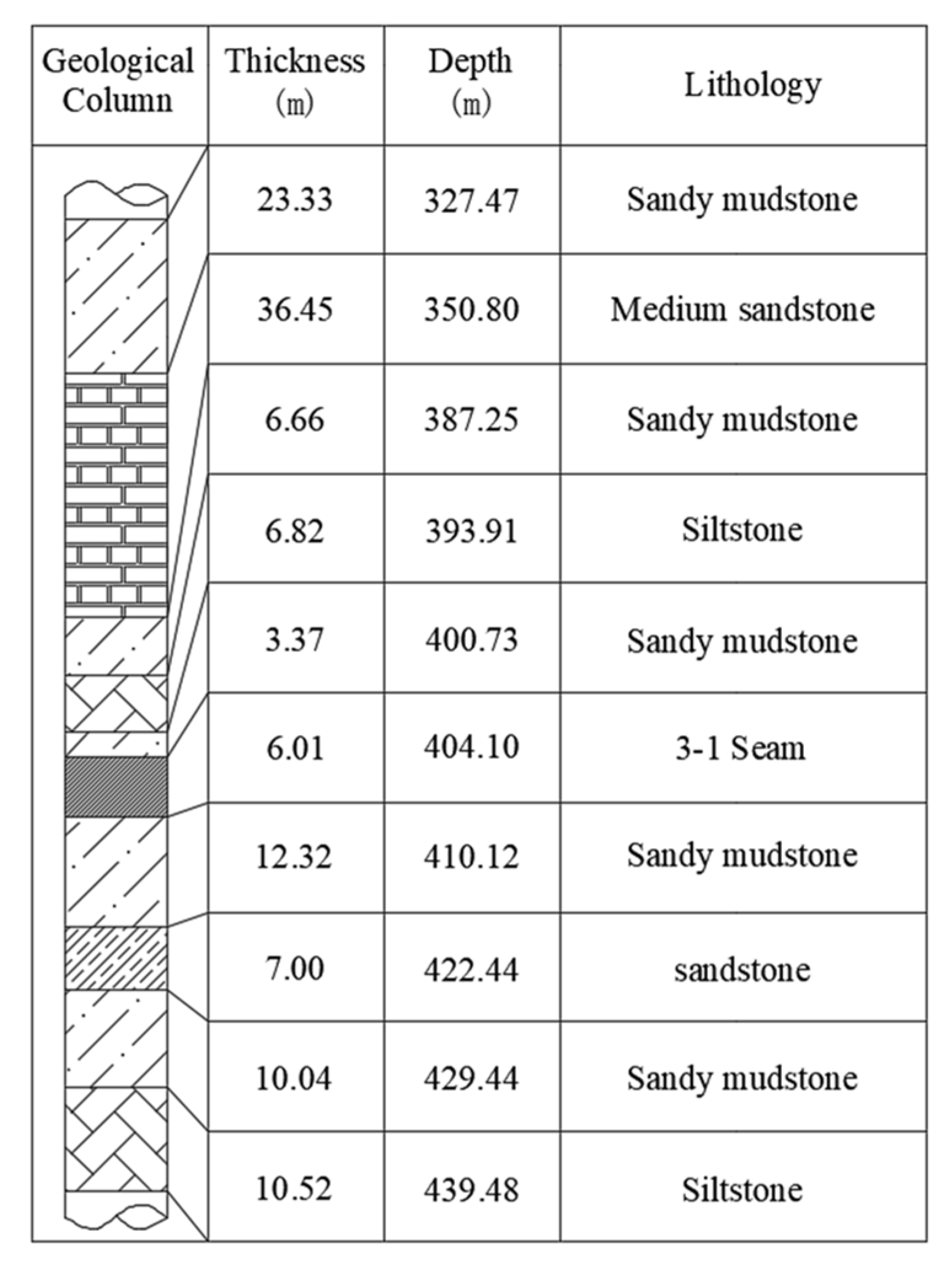
2.1. Geological and Geotechnical Overview of the Mataihao Mine

The 3-1 coal seam is being mined in Mataihao Mine. The buried depth of the coal seam is about 420 m, and the coal seam geological conditions are relatively simple. The working face adopts the full-height mining technology of large-cutting height and fully mechanized mining at the same time. The thickness of the top coal is 1 m, and that of the bottom coal is 1 m.
The panel of Mataihao Mine that has been mined is currently using wide yield pillars along the goaf side. The yield pillar size of the panel is 20 m along the goaf and the two lanes are driven together. Because the tail entry is affected by the two panels’ advanced dynamic pressures, the support of the tail entry is difficult, which seriously affects safety and production. Starting from panel 3108, Mataihao Mine has increased the yield pillar size to 35 m. However, increasing the yield pillar size has caused considerable loss of resources, and if there is potential shock pressure, the 35 m yield pillar will remain the same. It is difficult to control the dynamic pressure load, and the dynamic pressure shock phenomenon may occur in severe cases. For these reasons, Mataihao Mine chose to use yield pillars to the goaf-side entry between the head entry of panel 3103 and the tail entry of panel 3105. To determine the yield pillar size, theoretical analysis and numerical simulation are carried out.

2.2. Theoretical Demonstration and Analysis of Yield Pillar Width in Goaf-Side Entry

A reasonable yield pillar width means that the yield pillar cannot be too large, within the peak of the mine stress in the direction of the coal seam, and not too small, because the yield pillar is broken and cannot be anchored with bolts [19]. If the yield pillar is too large, it is not safe and economical; if the yield pillar is too small, owing to the plastic fracture zone on both sides of the yield pillar, the stability and bearing capacity are low. The anchor bolt anchoring in the plastic fracture zone cannot play a role in controlling the surrounding rock. Therefore, the yield pillar size has a reasonable interval that meets the above requirements in the range of 0–20 m. The reasonable width of yield pillars can be obtained by theoretical calculation methods. According to the theory of elastoplastic, the yield pillar width is analyzed theoretically, and the theoretical calculation method of the yield pillar is determined [20,21,22,23,24].
Calculation formula for the reasonable yield pillar width:
X   <   x 0   x
where X is a reasonable yield pillar width, x0 is the width of the stress limit equilibrium zone, and x is the width of the roadway.
Calculation formula for the width of the stress limit equilibrium zone:
x 0 = h A 2 tan φ 0 ln ( k γ H + C 0 tan φ 0 C 0 tan φ 0 + P x A )
A = μ 1 μ
where h is the height of the working surface, μ is the Poisson’s ratio, A is the lateral pressure coefficient, φ is the coal internal friction angle, k is the stress concentration coefficient, γ is the rock bulk density, H is the buried depth of the roadway, C0 is the cohesion, and Px is the strength of roadway support.
According to the value of each parameter, the theoretical value of reasonable yield pillar width is obtained: x0 = 14.5 m. Therefore, the reasonable yield pillar width is less than 8.5 m.
According to the engineering geological background of the Mataihao Coal Mine, theoretical calculations are carried out, and the reasonable theoretical value of yield pillar width is less than 8.5 m. To reasonably optimize the width of the yield pillar of the roadway, in the following chapters, the three-dimensional finite-difference software FLAC3D will be used to carry out the numerical simulation analysis of the case study.

3. Numerical Analysis of Ground Stability of Goaf-Side Entry

3.1. Establishment of Numerical Simulation Model for Goaf-Side Entry

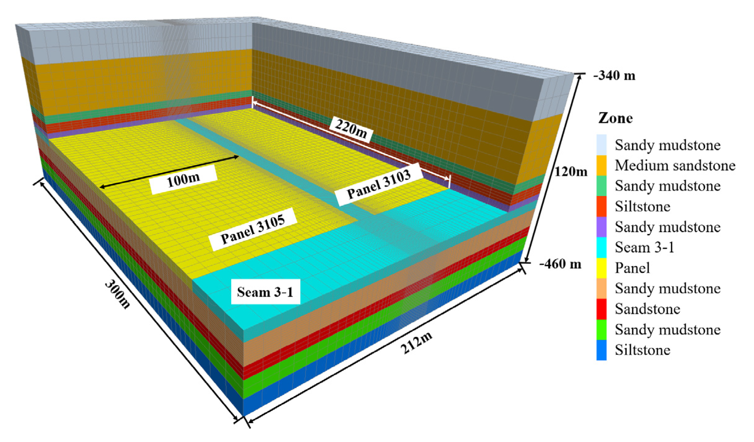
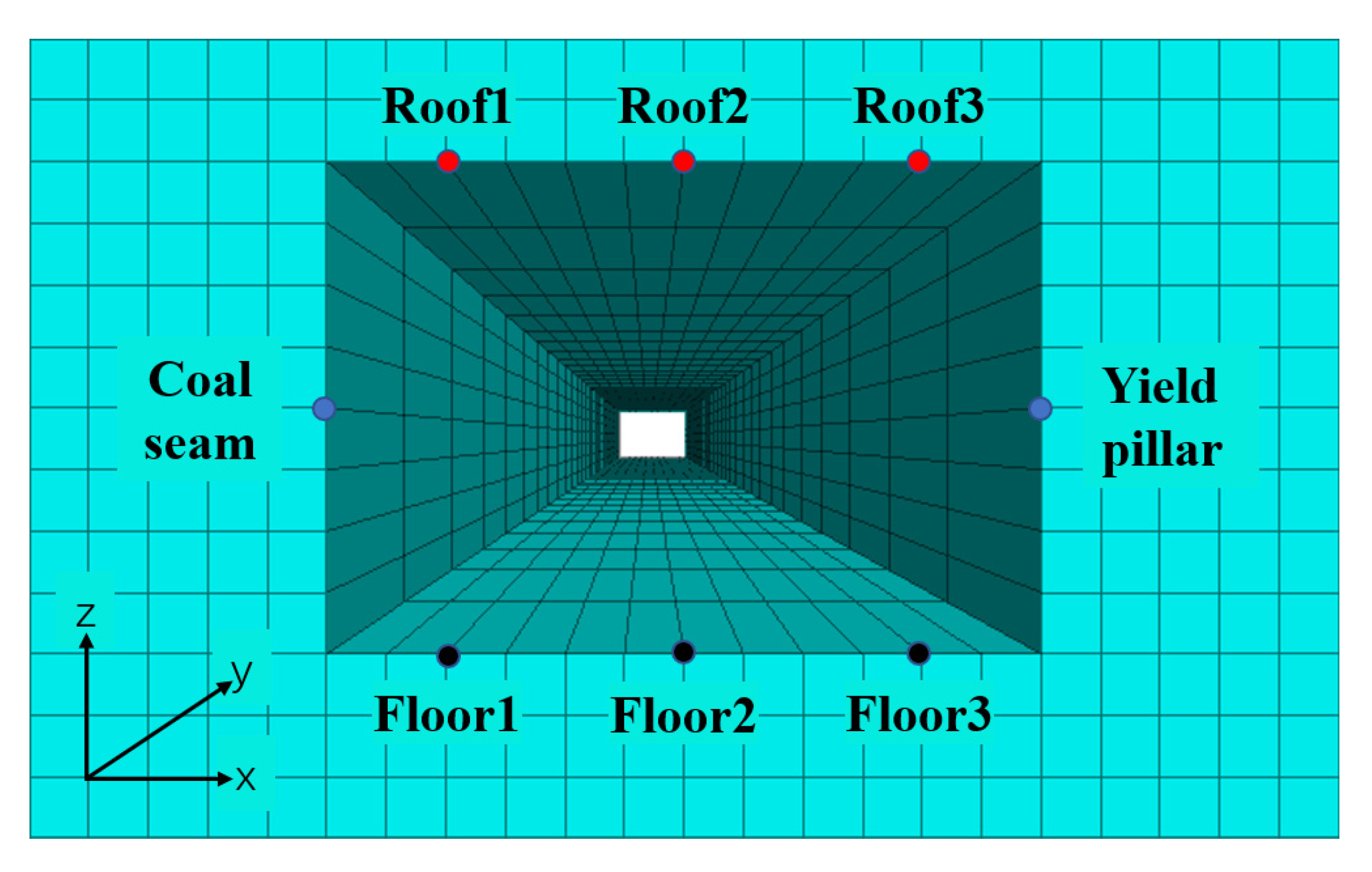
3.1.1. Three-Dimensional Numerical Model

Goaf-side entry involves arranging and excavating the roadway in the relatively low stress area in the residual bearing pressure area on the side of the goaf after the overlying rock migration adjacent to the goaf is basically stable.
The main coal seam of panel 3103 and panel 3105 in Mataihao Mine is 3-1 seam, and the three-dimensional numerical models of 4 m, 6 m, and 8 m yield pillar widths are established based on the model boundary of the inclined midline of panel 3103 and panel 3105 [25,26,27]. The numerical model diagram is shown in Figure 1. When studying the mechanical properties of rock masses in the collapse zone through numerical simulation, scholars all over the world generally recognize the double-yield model [28]. The mechanical properties of goaf are shown in Table 1. The type of analysis is elastoplastic. As the surrounding rock in this mine does not present notable strain-softening behavior, the Mohr–Coulomb model is employed to improve the simulation efficiency [29,30,31]. The model is 300 m long along the strike of the panel, of which the strike length of the work face is 220 m, with a boundary of 40 m at the front and rear; the length of the panel is 210, 212, and 214 m; and the height is 120 m. The in situ stress regime was first created in the model using the initial stress feature with gravity loading and a horizontal-to-vertical stress ratio of 1.5. The experimental results from previous rock mechanical testing [32] illustrated a linear yield or failure envelop, well described by the Mohr–Coulomb criterion. The rock mass properties, as listed in Table 1, are estimated from the intact rock properties using the generalized Hoek–Brown failure criterion [33].
The entry is driven along the goaf-side of 3103 with a 6 m wide yield pillar, as illustrated in Figure 2. The numerical simulation plan is shown in Figure 3. A typical geological column based on core logging was carried out in an adjacent panel 11,050, as shown in Figure 4. First, panel 3103 is mined. Because, after the completion of panel 3103, its head entry is destroyed, and tail entry 3105 of the research object needs to be re-excavated, the head entry 3103 part of the model is directly replaced by the double-yield model of panel 3103. After the mining of panel 3103 is completed, tail entry 3105 is excavated, and bolt and anchor cable support is carried out. After the roadway is excavated and supported, panel 3105 is mined.

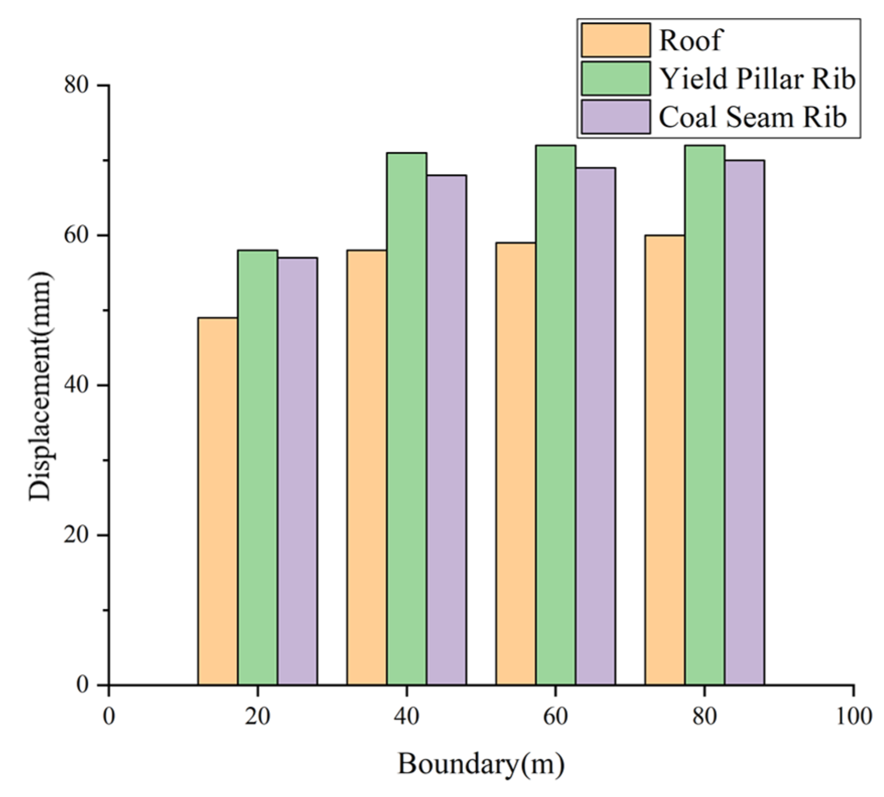
3.1.2. Sensitivity Analyses

  • Base boundary
To verify the boundary sensitivity, the same model as in Figure 2 was established and the displacement (The displacement direction of the roof in the text is vertical downward, and the displacement direction of the two ribs is the horizontal direction.) at 120 m of the roadway excavation was monitored. Figure 5 and Figure 6 illustrate that the distance between the yield pillar is 20 m, 40 m, 60 m, and 80 m, the roadway displacement and stress distribution are different. The stress values in the roof, floor, and two ribs of one roadway section are marked in Figure 6. As can be seen, when the boundary increases from 20 m to 40 m, the stress distribution in surrounding rocks changed; however, the change becomes negligible with the continuous increase in boundary size. Therefore, to reduce the calculation volume and the influence of the boundary effect on the model, the model with the boundary of 40 m is chosen.
  • Mesh dependency
The mesh density of the numerical model, especially for rock mass near roadway, might also be sensitive to the simulation results. Figure 7 illustrates the simulation results of roadway displacement at the last mining step with respect to different mesh density in its surrounding rock, and the number of zones in the roadway surrounding the area of model 1, 2, and 3 is 18,000, 36,000, and 54,000, respectively. As can be seen, the mesh sensitivity of displacement varies for roof and rib. Owing to the weaker properties, the ribs tend to fail more in tension, which leads to the effect of tension weakening being more significant than roof. As a result, displacements of rib are more sensitive to mesh density. As there is no notable difference between model 2, which is employed to carry out the simulations in the present study, and model 3, which has a denser mesh, its mesh density and simulation results are validated. This mesh dependency study indicates that the mesh density of the numerical model, especially for the areas where notable tensile failure will take place, should be calibrated.

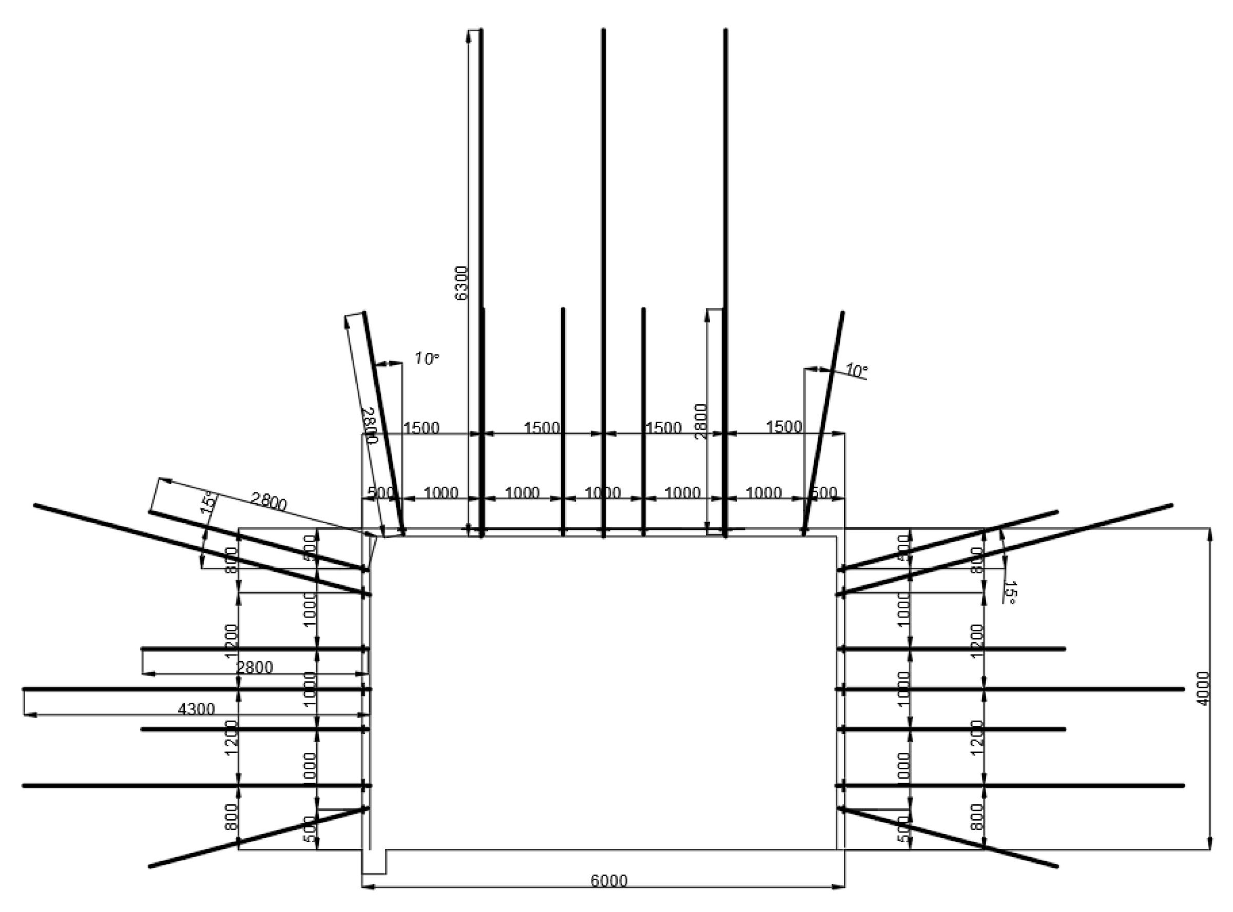
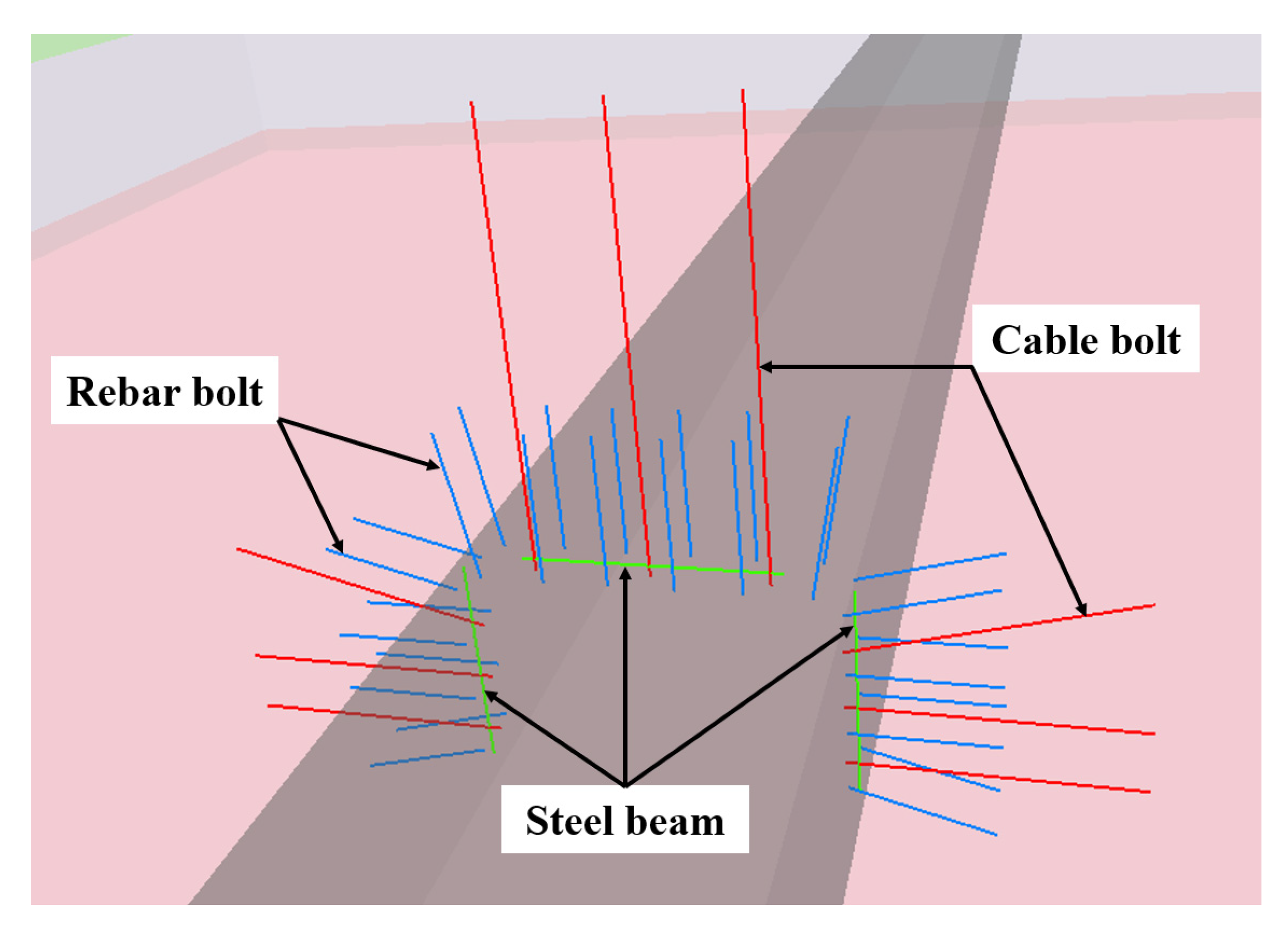
3.1.3. Simulation Scheme and Roadway Support

After panel 3103 is mined, the rock mass compaction, overlying rock migration, and stress adjustment in the caving zone form the surrounding rock conditions and stress environment before goaf-side entry. After the yield pillars with widths of 4 m, 6 m, and 8 m are employed, respectively, the tail entry of panel 3105 was excavated, and the roadway excavation width × height was 6 m × 4 m. The roadway support follows the excavation, and the roadway support design is shown in Figure 8.
The roadway support is simulated using structural elements in FLAC3D, and the support design used in the simulation is the same as the on-site application support scheme [34]. For the convenience of presentation, Figure 9 shows the support of a 2 m section of the tail entry of panel 3105. All rebar bolts and cable bolts are partially grouted with resin cartridges; the parameters are listed in Table 2. To comprehensively evaluate the surrounding rock and stress environment for goaf-side entry and optimize the reasonable layout of the goaf-side entry, the study is carried out from three aspects: the stress distribution of the surrounding rock, the distribution of the plastic failure zone, and the displacement and evolution characteristics of the surrounding rock during the roadway driving. The influence of yield pillar width on the behavior of underground pressure and the stability of surrounding rock during goaf-side entry is summarized.

3.2. Stress State and Mechanical Characteristics of Rock Surrounding the Roadway Goaf-Side Entry with Different Yield Pillar Widths

3.2.1. Boundary Stress Distribution Coal Seam Goaf before Goaf-Side Entry

The goaf-side entry is arranged in the area where the supporting pressure of the coal body is relatively low under the large lateral structure of the goaf. The disturbance to the overlying rock layer during the roadway excavation generally does not affect the stability of the large structure.
After the completion of mining panel 3103, the stress is re-adjusted and distributed in the adjacent surrounding rock to form the mining stress field in the upper section, which forms the surrounding rock and stress environment during the excavating of panel 3105 head goaf-side entry. Figure 10 shows the vertical stress distribution in the yield pillar in the monitoring section and the driving position of the tail entry of panel 3105 with different yield pillars. By observing the stress state of the surrounding rock before excavating with yield pillars of different widths, the larger the yield pillars’ width in isolated goaf, the higher the vertical stress of surrounding rock with goaf-side entry. Because the stress reduction area in the yield pillar causes the coal and rock mass to yield and fail owing to the impact of mining, it is formed by loosening and decompression. Therefore, the smaller the yield pillar width, the worse the conditions of the surrounding rock during roadway driving. In the process of redistribution, it is sensitive to stress changes, volatile failure, poor bearing capacity, and other mechanical characteristics. Owing to the large span of the roadway (6 m), the mechanical properties and stress state of surrounding rock on both sides of roadway roof and floor as well as the two sides of coal rock mass are different.

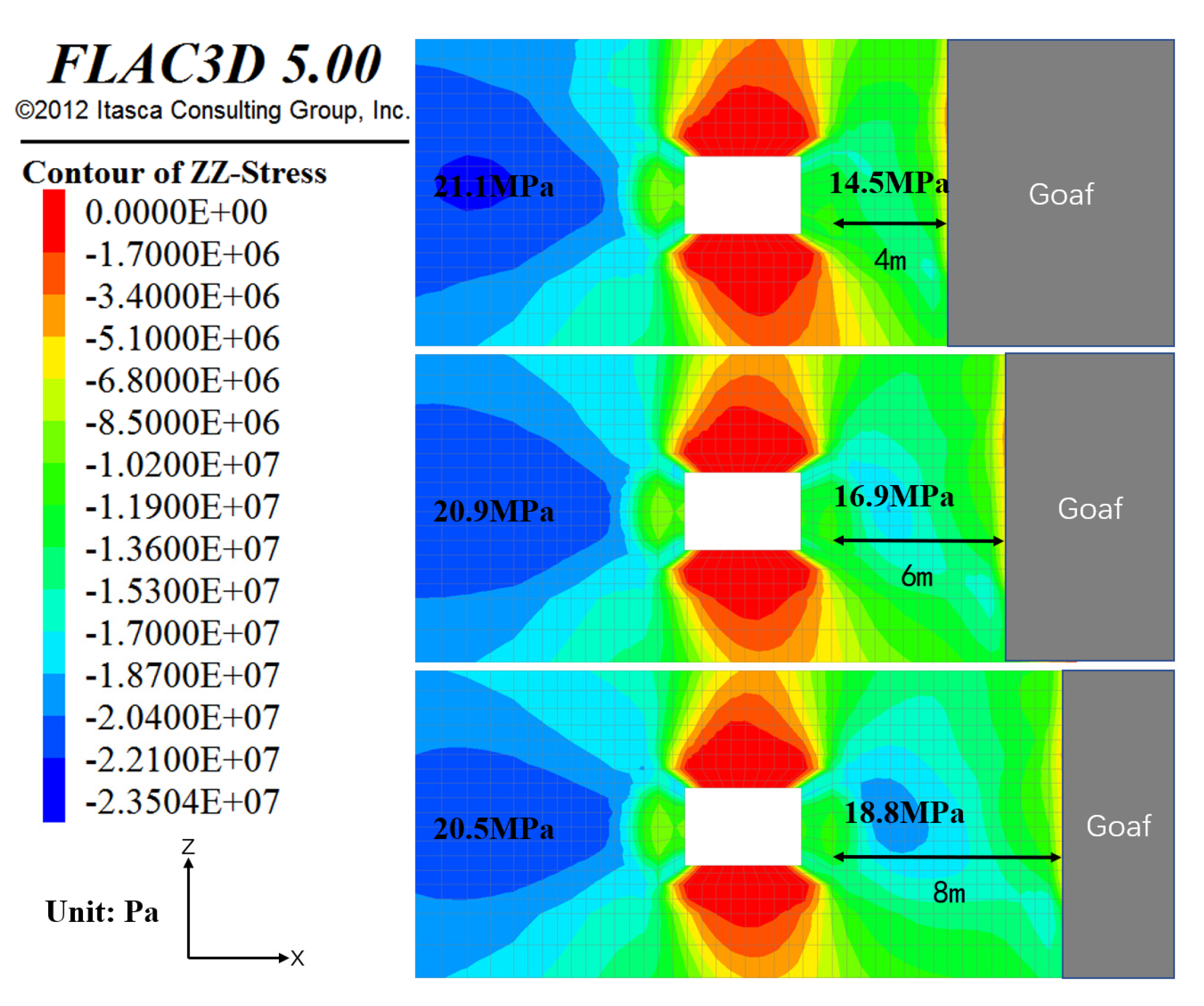
3.2.2. Stress State of Surrounding Rock of Roadway Driving along Goaf under Different Yield Pillar Widths

Figure 11 shows the vertical stress distribution in the surrounding rock after goaf-side entry with different yield pillar widths. When the yield pillar width is 4 m, the maximum vertical stress in the yield pillar is only 14.5 MPa. When the pillar width is 6 m, the maximum stress in the pillar is 16.9 MPa. When the pillar width is 8 m, the maximum stress in the pillar is 18.8 MPa. With the increase in pillar width, the vertical stress in the pillar increases. When the yield pillar width is 8 m, the maximum vertical stress in the yield pillar is more than twice of the original rock stress, and there is obvious stress concentration.
After the surrounding rock stress is redistributed, the concentrated stress shifts to the depth of the coal seam. The yield pillar width has almost no effect on the width of the stress limit equilibrium zone, but has a significant effect on the peak value of the vertical stress. When the yield pillar width is 4 m, the peak value of vertical stress in a deep coal seam is 21.1 MPa, which is 2.41 times the original rock stress. When the yield pillar width is 6 m, the peak value of vertical stress in a deep coal seam is 20.9 MPa, which is 2.38 times that of the original rock stress. When the yield pillar width is 8 m, the peak value of vertical stress in a deep coal seam increases to 20.5 MPa, which is 2.34 times that of the original rock stress. When the yield pillar width is 6 m, the vertical stress distribution of the yield pillar side and coal seam side is more uniform. When the pillar width is 4 m, the vertical stress is concentrated on the side of the coal seam. When the pillar width is 8 m, the vertical stress is concentrated on the pillar side. The internal stress distribution in the shallow surrounding rock (less than 2 m away from the surrounding rock surface) is almost not affected by the size of the yield pillar.

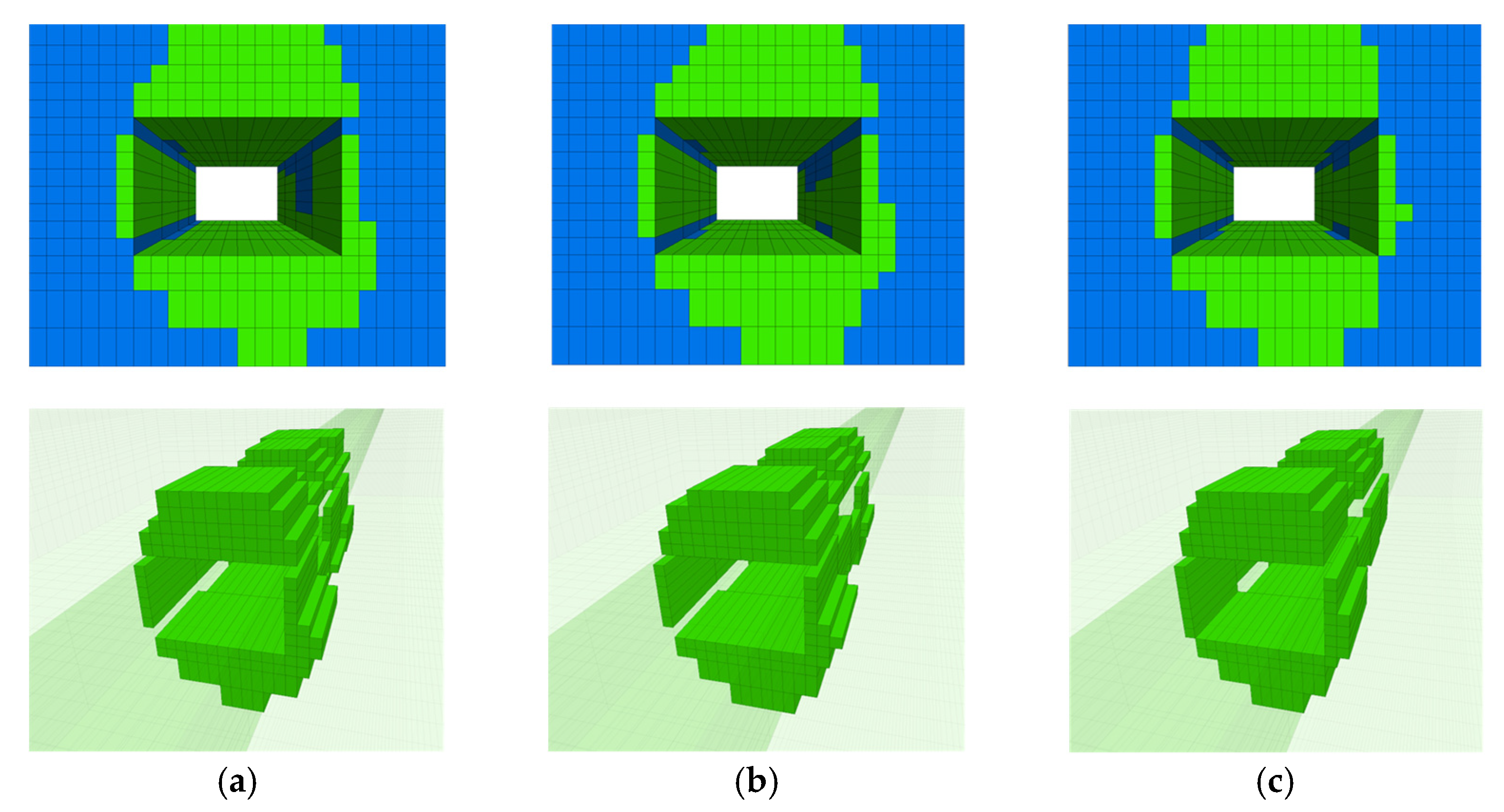
3.2.3. Development Characteristics of Tensile Failure of Surrounding Rock of Goaf-Side Entry

After roadway excavation, the original triaxial stress state is broken. Because the tensile strength of coal rock is far lower than the compressive strength, and the joints and fissures and other weak structural planes have almost no tensile strength, the surface and shallow surrounding rock of roadway are prone to tensile fracture and convergent displacement in roadway space. Therefore, the extension range of the shallow tensile failure zone in the plastic zone of roadway surrounding rock can be used as an effective index to measure the stability of roadway surrounding rock and analyze the failure mechanism of surrounding rock. At the same time, the plastic failure zone caused by the influence of mining in the upper section before roadway excavation can be distinguished from the plastic failure zone caused by the influence of goaf-side excavation.
Through the FLAC3D built-in FISH language programming, the tensile failure elements in the shallow surrounding rock of goaf-side excavation were identified and counted, and the distribution of tensile failure zones along axial and vertical sections of a certain section of goaf-side excavation with different yield pillar widths is shown in Figure 12. By comparing the distribution of the tensile failure zone of the surrounding rock of goaf excavation with different yield pillar widths in Figure 12 under the condition of different yield pillar widths, the common feature of surrounding rock failure is that the tensile failure zone is more widely distributed and extends deeper on the roof and floor of the roadway. This is because the tail entry of panel 3105 is excavated in the coal seam, and the roof strata, two sides, and floor are all weak coal bodies, which can easy lead to displacement and failure.
The ratio of the number of tensile failure elements calculated by the FISH language program to the total number of surrounding rock elements in the shallow part of the roadway was obtained, and the tensile failure ratio of the shallow surrounding rock is shown in Table 3.The failure characteristics of surrounding rock in different yield pillar widths were analyzed in combination with Figure 12. When the yield pillar width is 4 m, closest to the mines’ yield pillar, the most dramatic effect by mining of coal and rock roadway roof and floor yield pillar side caused severe tensile fracture, because, before the roadway, the surrounding rock mechanics properties are poor, and the depth of the scope of tensile fracture at the side of the pillar to the roof and floor is 32.05% of the whole roadway surrounding the rock of shallow tensile failure. When the yield pillar width is 6 m, the mechanical properties of rock mass before excavation are improved, the tensile failure in the roof is slightly smaller than that of the 4 m yield pillar, and the failure is relatively symmetrical. Moreover, 29.73% of the shallow surrounding rock in the whole roadway is subjected to tensile failure. When the yield pillar width is 8 m, the mechanical properties of surrounding rock before excavation are good, but the stress of the surrounding rock is high. Tensile failure occurs in 28.69% of the shallow surrounding rock in the whole roadway.

3.3. Evolution of Surrounding Rock Displacement of Goaf-Side Entry under Different Yield Pillar Widths and the Effect of Yield Pillar Size

In order to comprehensively study the surrounding rock displacement in the whole section of the roadway during excavating and panel mining, eight displacement monitoring nodes are arranged in the monitoring section, as shown in Figure 13. Note that the roof displacement is considered as the vertical displacement towards the floor, the floor displacement is considered as the vertical displacement towards the roof, and the converging displacement of the two ribs is horizontal displacement towards the other rib.
Along the direction of roadway excavation, the right side is the yield pillar left, and the left side is the coal seam to be recovered. Displacement measuring points are arranged on the left side of the roof of the roadway roof, the center of the roof, and the right side of the roof to monitor the amount of roof subsidence and displacement, which are marked in red as Roof 1, Roof 2, and Roof 3, respectively, arranged on the coal seam and yield pillar; the displacement measuring points are moved closer to each other horizontally and marked in blue; and the displacement measuring points are arranged on the left, center, and right of the bottom of the roadway floor to monitor the displacement of the bottom drum, marked in black as Floor 1, Floor 2, and Floor 3.

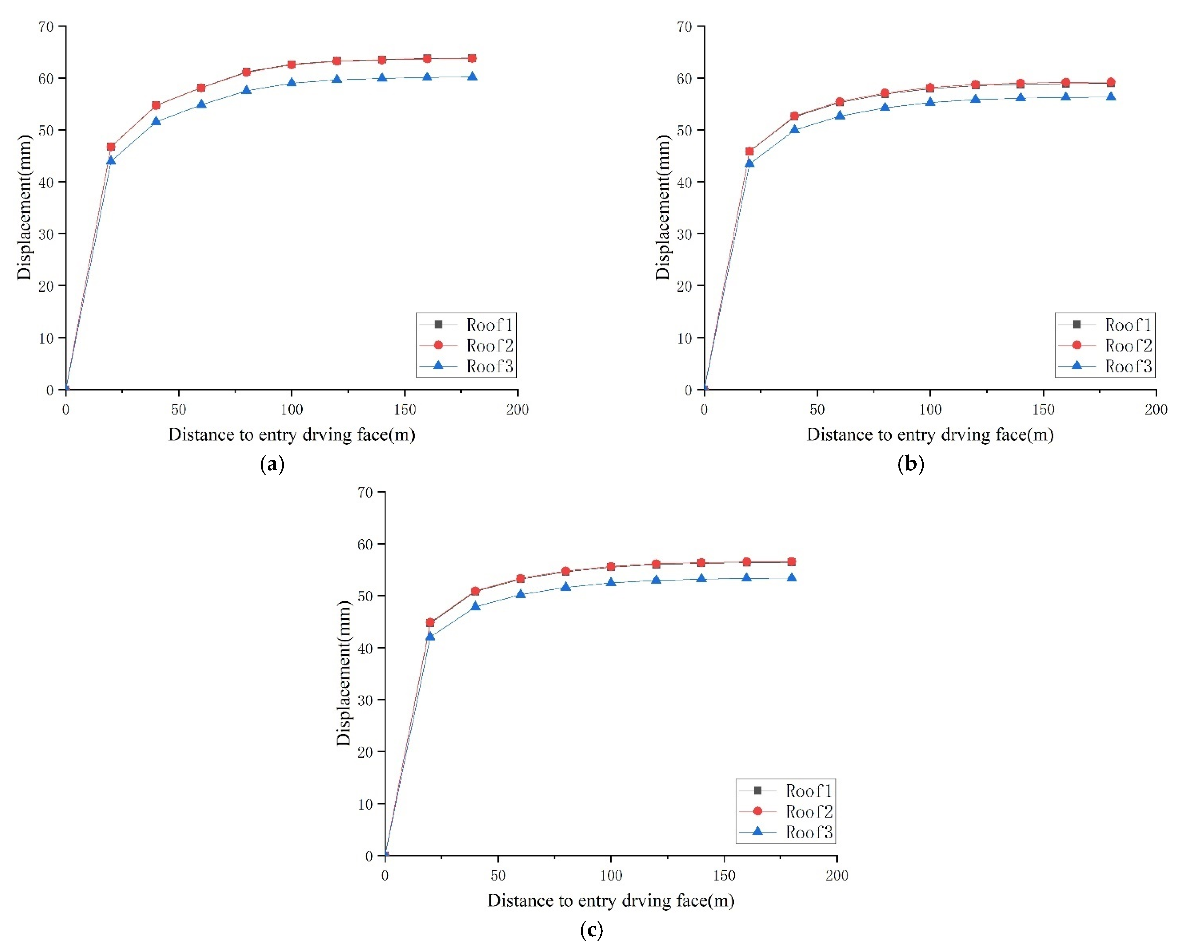
3.3.1. Evolution of Roof Displacement during Goaf-Side Entry

Under the condition of keeping yield pillars of different widths, the displacement evolution characteristics of the roof in the monitoring section of goaf excavation during excavation are shown in Figure 14. For convenience, the absolute value of roof subsidence displacement is adopted in the figure. Monitoring begins after excavation of the roadway in the monitoring section and ends after excavation of the roadway. It can be seen from Figure 14 that the continuous displacement time of surrounding rock is long, the stability speed of surrounding rock is slow, and the creep characteristics are obvious after the roadway is excavated. Specifically, during the process of 20 m~60 m in the advance monitoring section of the driving face, the roof subsidence increases by 7 mm~8 mm under the condition of each yield pillar width. During the process of 60 m~100 m in the advance monitoring section of the driving face, the roof displacement tends to be stable and the subsidence amount increases by about 4 mm.Different widths of yield pillars along the goaf-side mean that roadways are driven in different loose and broken surrounding rock environments and different stress concentrations in stress environments. Comparing Figure 14a–c, the influence of the yield pillar width on the roof displacement of roadway driving along the goaf is not only reflected in the amount of subsidence, but also has a significant influence on the shape of the roof displacement.
The monitoring positions of the roof of the roadway deformed rapidly after the roadway was excavated, and then the displacement rate slowed down with the continuous advancement of the driving face, but a certain displacement rate was still maintained. For different yield pillar widths, the average roof displacement of the monitoring section at different stages of roadway excavation (the distance between the excavation work surface and the monitoring section) and the ratio of the total displacement during the roadway excavation period are shown in Table 4. First, the yield pillar width has a significant impact on the total roof displacement during the goaf-side entry. The roof subsidence is the largest when the pillar width is 4 m, the second largest when the pillar width is 6 m, and the roof displacement is the smallest when the pillar width is 8 m. Secondly, the ratio of existing displacement to the total displacement at different stages during roadway excavation (hereinafter referred to as the displacement ratio) is also affected by the yield pillar width. When the yield pillar width is 4 m, the roof displacement speed is slow after the roadway is excavated, and the displacement is small. The roof displacement after the excavating work surface passes the monitoring point accounts for 73.51% of the total displacement during the excavating period. The roof displacement ratio shows an upward trend with the increase in the yield pillar width. When the yield pillar width is 8 m, the roof displacement ratio at the same stage is 79.46%, and the displacement ratio difference is 5.95%. When the driving surface is advanced to 60 m from the monitoring section, the roof displacement and displacement ratio of the roadway under each yield pillar condition increase. It can be seen that the excavating displacement mainly occurs from the time the section is excavated to the lagging excavating surface of 0–60 m, that is, the excavating influence period. The difference between the roof displacement ratio of the 4 m yield pillar and the 8 m yield pillar is 2.95%, and the evolution trend of roof displacement remains unchanged. When the driving surface is further advanced to 100 m from the monitoring section, the roof displacement ratio difference of different yield pillar widths is significantly reduced, and the roadway roof displacement ratio difference between the 4 m yield pillar and the 8 m yield pillar is only 0.1%. At this stage, the roof displacement was 4.35 mm and 2.29 mm, respectively, and the roof displacement ratio was 98.56% and 98.66%, respectively.
The above-mentioned roadway roof displacement and displacement rate evolution characteristics are affected by the yield pillar width and the difference is caused by the different surrounding rock and stress environment of the road excavation position with different yield pillar widths [35]. The smaller the yield pillar width, the worse the mechanical properties of the surrounding rock under the influence of mining in the upper section of the goaf-side entry, and the lower the stress of the surrounding rock. Therefore, the weak and broken surrounding rock rapidly deforms after the roadway is driven, and the displacement rate is high at the initial stage of roadway driving. After entering the stable stage after excavation, because the surrounding rock stress is low, the stress environment is good, and the creep amount in the later stage is small. The greater the yield pillar width, the better the mechanical properties of the surrounding rock during roadway excavation, but the higher the stress concentration at the roadway location. After the roadway is excavated, the more complete surrounding rock will gradually deform and fail during the stress adjustment process, and the initial displacement rate of the roadway will be slightly lower, but it is affected by a high-stress environment in the later stage, and still maintains a high creep value [36].
Under the conditions of different yield pillar widths, the vertical roof displacement distribution cloud diagram of the goaf-side entry monitoring section after the roadway excavation is completed is shown in Figure 15. Through comparison, it can be seen that the yield pillar width also has a significant effect on the roof displacement of the goaf-side entry. Figure 16 respectively lists the displacement evolution law of three different monitoring nodes on the roof during the roadway excavation. Under the influence of different yield pillar widths, the relative displacement and displacement rate of each position of the roof are significantly different, and the displacement and displacement of the roof subsidence after the completion of the roadway are also significantly different, as shown in Figure 16. It can be seen from Figure 14, Figure 15 and Figure 16 that, during the goaf-side entry, the overall displacement of the roadway roof is large when the yield pillar is 4 m, and significant asymmetric large displacement occurs on the side of the yield pillar; when the yield pillar width is 6 m, the roadway displacement of the roof is slightly larger than the 8 m yield pillar, but the difference is not much.

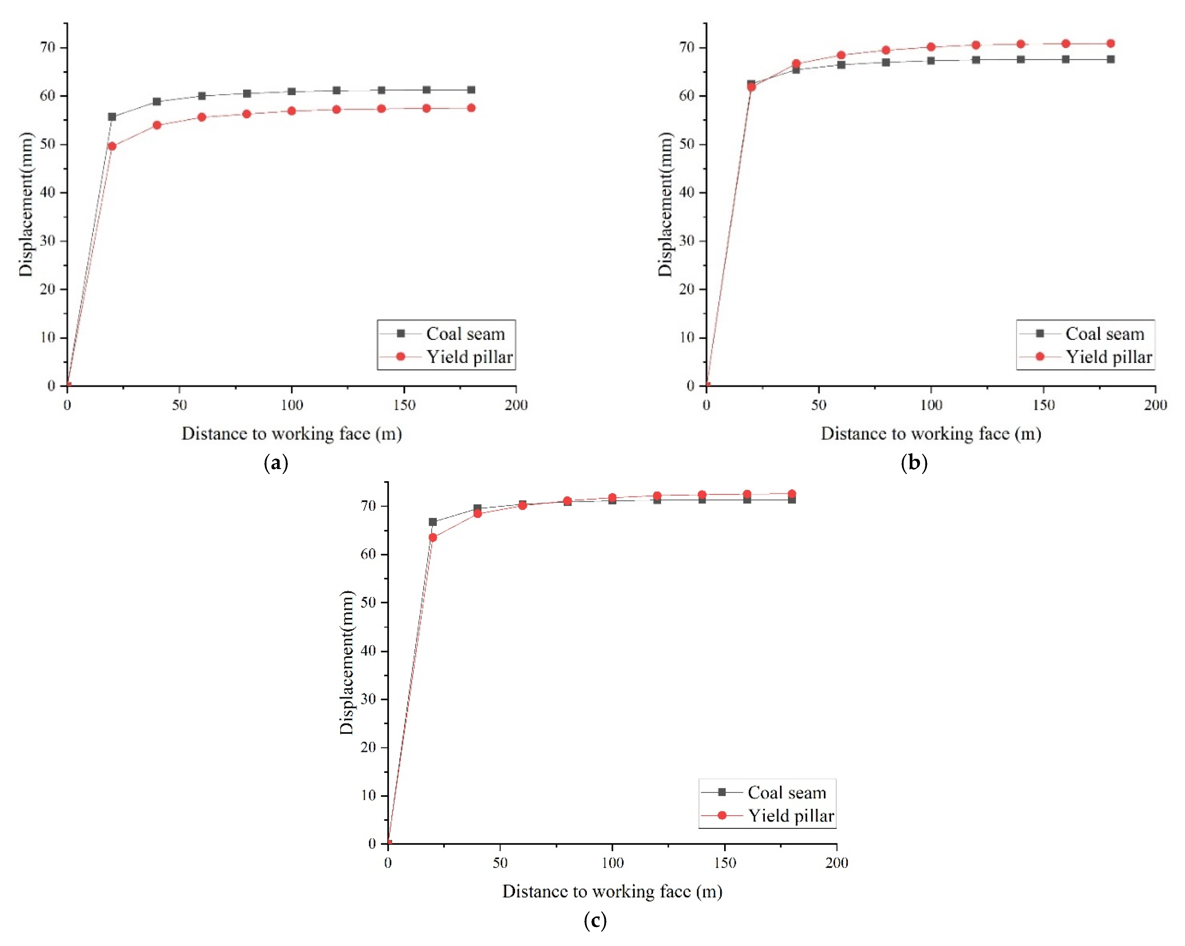
3.3.2. Displacement Evolution of Two Sides during Roadway Driving along the Goaf-Side

With the conditions of different yield pillar widths, the displacement evolution characteristics of the two sides of the goaf-side entry during the excavating stage are shown in Figure 17. For ease of presentation, the absolute value of the displacement of the two sides is used in the figure.
Like the roof displacement characteristics, both sides are rapidly deformed after driving along the goaf-side, and then the displacement rate slows down with the continuous advancement of the driving face, but a certain displacement rate is still maintained. The moving of the two sides shows the creep characteristics of the sustained displacement time is shorter than the roof sinking, and the surrounding rock has a faster stable speed. This feature is significantly affected by the yield pillar widths. The approaching amount and approaching displacement of the two sides of the roadway monitoring section at different stages of driving influence are shown in Table 5 and Table 6. When the yield pillar width is 8 m, the displacement speed of the two sides of the roadway in the monitoring section is fast and the amount of displacement is large, especially the sudden displacement of the yield pillar. When the lagging excavating working surface is 20 m, the displacement ratio of the two sides approaching reaches 87.71%. The displacement ratio of the two sides basically shows a downward trend as the yield pillar width decreases. When the yield pillar width is 4 m, the displacement ratio of the two sides at the same stage is 86.45%. When the driving surface is further advanced to 60 m from the monitoring section, the two coal bodies move closer and converge in the roadway under the influence of the driving. The displacement ratio of the 4 m yield pillar of the roadway and the coal seam reaches 96.97% and 98.09%, respectively, while the displacement ratio increases with the increase of the yield pillar width in the coal seam and there is no obvious law for the yield pillar. When the yield pillar width is 8 m, the ratios are 96.84% and 98.75%, respectively. From the excavating work surface to the monitoring section, it is 60 m from the monitoring section until the roadway excavating is completed, that is, the excavating stable period.
Under the conditions of different yield pillar widths, the horizontal displacement distribution cloud diagrams of the two sides of the goaf-side entry monitoring section after the roadway excavation is completed are shown in Figure 18. Through comparison, it can be seen that the yield pillar widths have two effects on the goaf-side entry. The deformed shape of the rib also has a significant impact. It can be seen from Figure 18 and Figure 19 that, when the yield pillar width is 6 m and 8 m, the coal body of the pillar side is significantly affected by the mining of the upper section. The difference between the displacement of the two sides is significantly affected by the yield pillar width. When the yield pillar width is 4 m, the displacement of the yield pillar ledge is less than the displacement of the coal seam after the roadway driving is completed, the displacement of the yield pillar ledge reaches 56.90 mm, and the displacement of the coal ledge is 60.92 mm between the two sides The difference in displacement is 3.98 mm, and the two sides show weak asymmetric displacement. When the yield pillar width is 6 m and 8 m, the displacement difference between the two sides is 2.84 mm and 0.67 mm, respectively. The displacement difference between the two sides is small, and the weak asymmetric displacement is negligible.

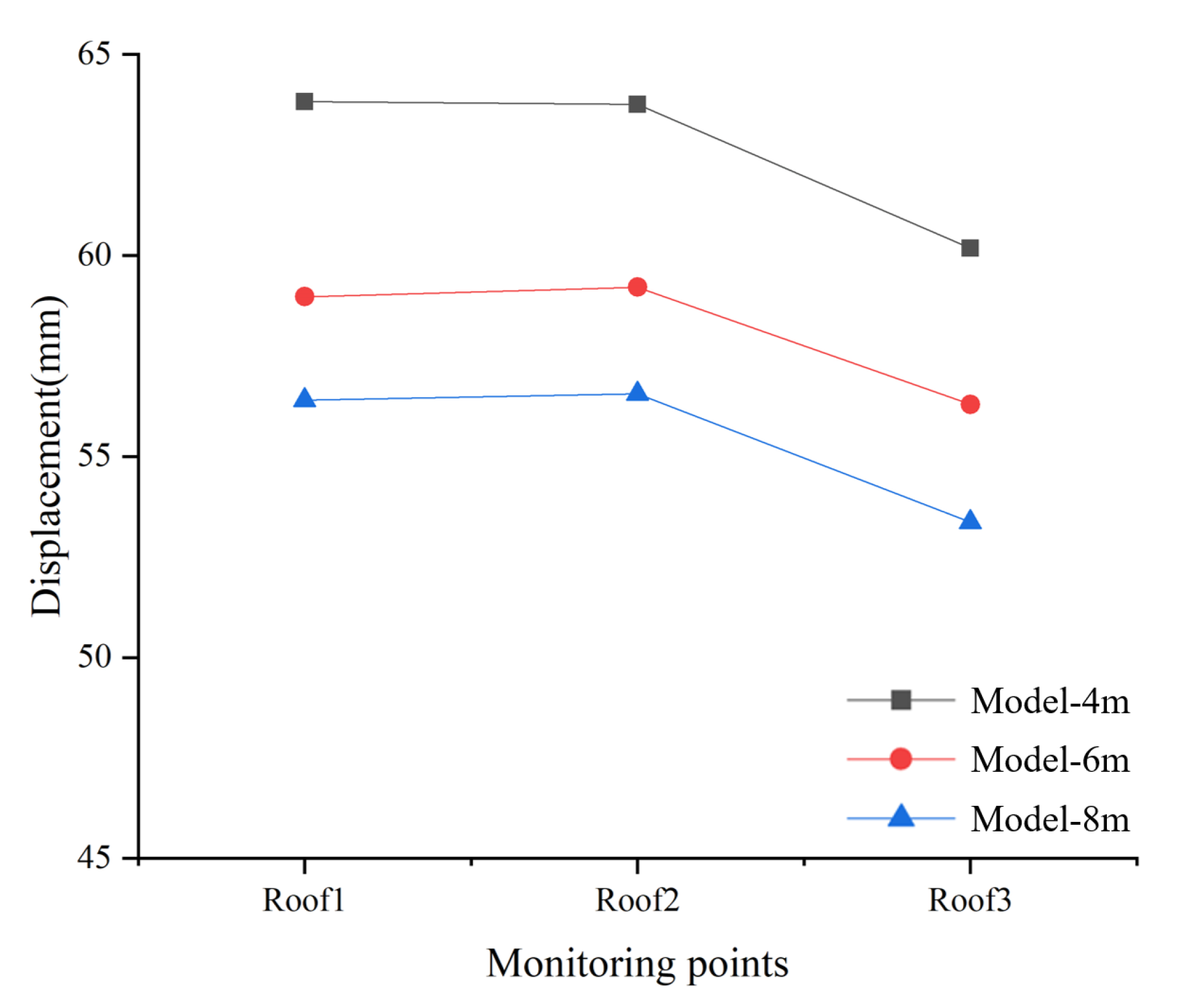
3.3.3. The Influence of Different Yield Pillar Width on the Displacement of Surrounding Rock during Roadway Driving

From the displacement and evolution of surrounding rock, the influence of yield pillar width on the appearance of pressure in the mine during the goaf-side entry is analyzed. Under the current geological occurrence and engineering technical conditions, when the yield pillar width is 4 m, the roof subsidence is the largest; when the yield pillar width is 8 m, the displacement of the two sides of the roadway is the largest among the three schemes, and the position of the roadway before the excavation of the roadway is a vertical stress concentration area, which is prone to impact accidents; when the yield pillar width is 6 m, the displacement of the roof, the two sides, and the floor is small. This law confirms the theoretical correctness and design superiority of employing yield pillars to protect the roadway when driving in completely along the goaf-side. Because the roadway is located in the coal seam, the physical and mechanical properties of the roof rock layer are the same as those of the two ribs and the floor coal. The approaching displacement is greatly affected by the width of the yield pillar, and when the yield pillar width is 6 m, more coal is saved than when the yield pillar width is 8 m. Based on the above considerations, when the yield pillar width is 6 m, the plan is the best. Therefore, when the wide yield pillars are changed to yield pillars in Mataihao Mine, the scheme with a yield pillar width of 6 m is preferred.

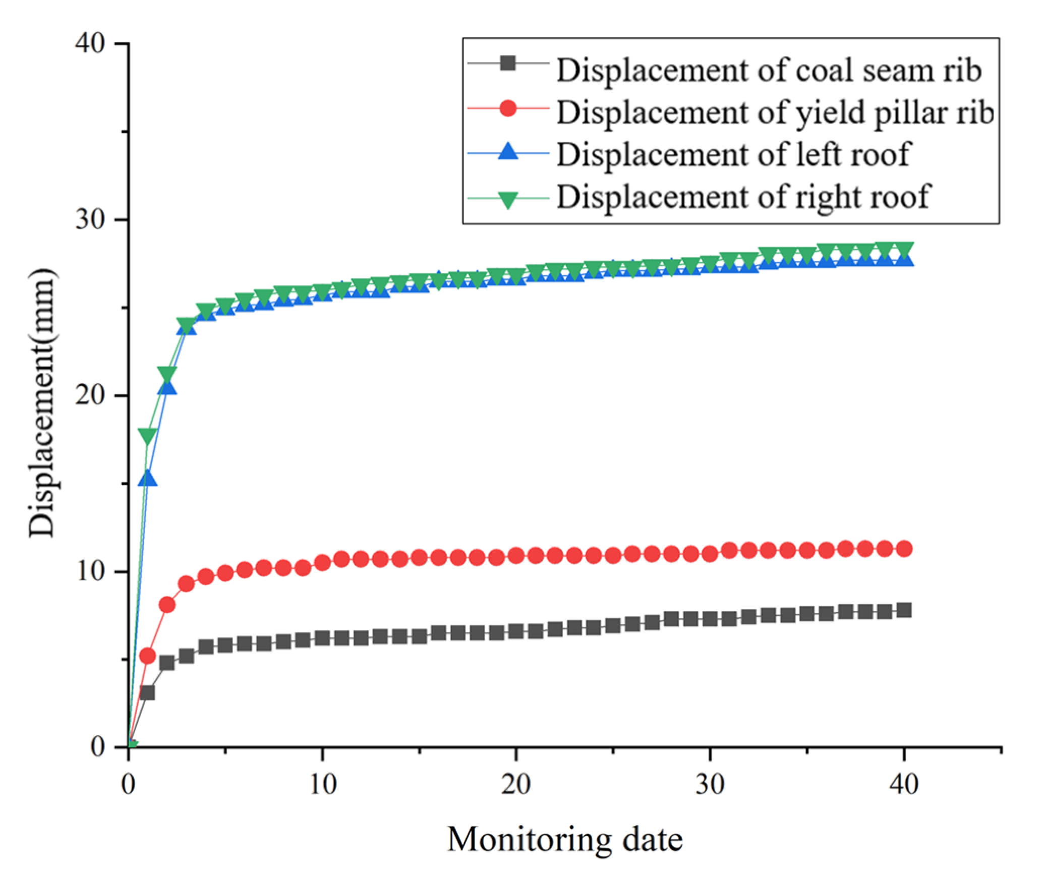
3.4. Field Monitoring and Observation

The tail entry 3105 is a test goaf-side entry with small yield pillars, with a yield pillar width of 6 m. Before mining in panel 3105, the tail entry is only affected by the excavation, and the displacement of the surrounding rock of the roadway is relatively small. In order to deeply study the mechanism of displacement and failure of surrounding rock of goaf-side entry, and to provide guidance and basis for the layout and support design of roadway under similar conditions, the monitoring of the surrounding rock displacement of the tail entry 3105 was carried out, and the failure mechanism and the control strategy research provide detailed and reliable actual data. Set up monitoring points when driving to 200 m, record data every day, and obtain on-site monitoring data, as shown in Figure 20.
In field practice, the amount of surrounding rock displacement is a direct indicator of engineering research to measure the stability of the surrounding rock of the roadway and the reliability of support [37,38]. Through the field data analysis, the detection starts when the roadway excavation reaches the detection point. With the passage of the working face, the roadway surrounding rock is relatively stable, the displacement is small, and there is no obvious asymmetry in the roadway roof. The actual displacement state of the surrounding rock of the roadway is shown in Figure 21. The displacement of the yield pillar is larger than that of the coal seam, but it is also basically stable. To validate the employed numerical approach and suggested design, a field test was carried out at the head entry of panel 3105. The field monitoring results indicate the success of the surrounding rock of roadway control by employing a yield pillar with a 6 m width and serve to validate the numerical approach.

4. Discussion

Through the study of displacements, plastic failure evolution of surrounding rock, and ground pressure behavior during the excavation of the entry along the goaf, it is shown that after the overburden structure of the mined-out area in the upper section is stabilized, and the goaf-side entry mainly plays a role of isolation. The yield pillar width has a greater impact on the surrounding rock conditions and the mechanical environment where the roadway is located.
The displacement evolution characteristics of the two sides of the goaf-side entry under the influence of the yield pillar width are consistent with the laws and mechanisms of the roof displacement evolution characteristics, and they are all caused by the different surrounding rock and stress environment of the roadway location under different yield pillar widths. When the yield pillar width is small, it is necessary to ensure the timeliness and effectiveness of temporary support and one-time support during the excavation to avoid problems such as roof collapse caused by the rapid displacement of broken surrounding rock after the roadway is excavated. When the yield pillar width is large, it is necessary to carry out regular and timely monitoring of surrounding rock displacement behind the working surface of the roadway and prevent slow creep behaviour from causing support failures and large displacements.

5. Conclusions

In this study, it is shown that adopting reasonable yield pillar is crucial for the efficiency and safety of the goaf side roadway. A reasonable pillar width means that it cannot be too large, otherwise it will be stiff enough to attract high stress in the direction of the coal seam. Moreover, it cannot be too small, otherwise it will fail, and it will not be possible to anchor broken rock. According to the theoretical calculations, with the existing geological conditions in seam 3-1, the reasonable yield pillar width is 4 to 6 m. According to field data measurement, when the yield pillar width is less than 8.5 m, the roadway maintains a stable condition.
Considering comprehensively the pressure and support of the mine along the goaf with high mining height, the isolation and ventilation safety of the goaf, the recovery rate of coal resources in the mining area, and the social and economic benefits, a 6 m yield pillar is employed along the goaf-side, which is more conducive to the roadway. During excavation and mining, the surrounding rock is stable, and the yield pillar can accommodate the depth of anchoring support, which can reduce the amount of roadway maintenance. At the same time, the yield pillar has a better isolation effect; it can further improve the coal mining rate as well as the economic and social benefits.

Author Contributions

Conceptualization, Q.W.; methodology, L.J.; software, Q.W.; validation, H.S.M., H.F. and P.T.; data curation, Q.W.; writing—original draft preparation, Q.W.; writing—review and editing, C.L. and Y.P.; funding acquisition, L.J. All authors have read and agreed to the published version of the manuscript.

Funding

This research was funded by the National Natural Science Foundation of China, grant number 52074166; the China Postdoctoral Science Foundation, grant number 2020T130385; the Natural Science Foundation of Shandong, grant number ZR2021YQ38; and the Climbing Project of Taishan Scholar in Shandong Province, grant number tspd20210313.

Institutional Review Board Statement

Not applicable.

Informed Consent Statement

Not applicable.

Data Availability Statement

Not applicable.

Conflicts of Interest

The authors declare no conflict of interest.

References

  1. Fan, L.; Liu, S. Respirable nano-particulate generations and their pathogenesis in mining workplaces: A review. Int. J. Coal Sci. Technol. 2021, 8, 179–198. [Google Scholar] [CrossRef]
  2. Zhang, B.; Wang, P.; Cui, S.; Fan, M.; Qiu, Y. Mechanism and surrounding rock control of roadway driving along gob in shallow-buried, large mining height and small coal pillars by roof cutting. J. China Coal Soc. 2021, 46, 2254–2267. [Google Scholar]
  3. Colwell, M.; Hill, D.; Frith, R. ALTS II, A longwall gateroad design methodology for Australian collieries. In Proceedings of the 1st Australian Conference on Ground Control in Mining, Sydney, Australia, 10–13 November 2003; pp. 123–135. [Google Scholar]
  4. Qi, Q.; Li, Y.; Zhao, S.; Zhang, N.; Zheng, W.; Li, H.; Li, H. Seventy years development of coal mine rock burst in China: Establishment and consideration of theory and technology system. Coal Sci. Technol. 2019, 47, 1–40. [Google Scholar]
  5. Du, J.; Meng, X. Mining Science; China University of Mining and Technology Press: Xuzhou, China, 2009; pp. 122–130. [Google Scholar]
  6. Hou, C.; Li, X. Stability principle of large and small structures of surrounding rock in gob-side driving roadway of fully mechanized caving. J. China Coal Soc. 2001, 26, 1–7. [Google Scholar]
  7. Maleki, H.N. Ground response to longwall mining: A Case study of two-entry yield pillar evolution in weak rock. Colo. Sch. Mines Q. 1988, 83, 51. [Google Scholar]
  8. Maleki, H.N. An analysis of violent failures in US coal mines—Case studies. In Proceedings of Mechanics and Mitigation of Violent Failure in Coal and Hard-Rock Mines; Maleki, H., Wopat, P.F., Repsher, R.C., Tuchman, R.J., Eds.; SP 01-95; US Bureau of Mines: Washington, DC, USA, 1995; pp. 5–26. [Google Scholar]
  9. Xue, K.; Fu, B. Research and application of reasonable width of coal pillars in roadway excavation. J. Undergr. Space Eng. 2018, 14 (Suppl. 1), 403–408. [Google Scholar]
  10. Chen, W. Study on control technology of rockburst in coalmines of Western Erdos. Coal Sci. Technol. 2018, 46, 99–104. [Google Scholar]
  11. Zhang, G.; He, F. Asymmetric failure and control measures of large cross-section entry roof with strong mining disturbance and fully-mechanized caving mining. Chin. J. Rock Mech. Eng. 2016, 35, 806–818. [Google Scholar]
  12. Wang, D.; Li, S.; Wang, Q.; Li, W.; Wang, F.; Wang, H.; Peng, P.; Ren, G. Experimental study of reasonable coal pillar width in fully mechanized top coal caving face of deep thick coal seam. Chin. J. Rock Mech. Eng. 2014, 33, 539–548. [Google Scholar]
  13. Hou, C.; Mines, C.O. Key technologies for surrounding rock control in deep roadway. J. China Univ. Min. Technol. 2017, 46, 970–978. [Google Scholar]
  14. Wang, W.; Hou, C. Study of mechanical principle of floor heave of roadway driving along next goaf in fully mechanized sub-level caving face. J. Coal Sci. Eng. 2001, 7, 13–17. [Google Scholar]
  15. Wang, Y.; He, M.; Yang, J.; Fu, Q.; Gao, Y.; University, T. The structure characteristics and deformation of “short cantilever beam” using a non-pillar mining method with gob-side entry formed automatically. J. China Univ. Min. Technol. 2019, 48, 718–726. [Google Scholar]
  16. Mark, C.; Mclinda, G.M.; Dolinar, D.R. Analysis of rock bolting systems. In Proceedings of the 20th International Conference on Ground Control in Mining, Morgantown, WV, USA, 7–9 August 2001; pp. 123–125. [Google Scholar]
  17. Mark, C.; Dolimar, D.R. Development and application of the coal mine roof rating (CMRR)—A decade of experience. Int. J. Coal Geol. 2005, 46, 85–103. [Google Scholar] [CrossRef]
  18. Esterhuizen, G.S.; Gearhart, D.F.; Klemetti, T.; Dougherty, H.; van Dyke, M. Analysis of gateroad stability at two longwall mines based on field monitoring results and numerical model analysis. Int. J. Min. Sci. Technol. 2019, 29, 35–43. [Google Scholar] [CrossRef]
  19. Shabanimashcool, M.; Li, C.C. Numerical modelling of longwall mining and stability analysis of the gates in a coal mine. Int. J. Rock Mech. Min. Sci. 2012, 51, 24–34. [Google Scholar] [CrossRef]
  20. Bai, J.; Hou, C.; Huang, H. Numerical simulation study of stability of narrow coal pillar of roadway driven along the goaf. Chin. J. Rock Mech. Eng. 2004, 20, 3475–3479. [Google Scholar]
  21. Qian, M.; Shi, P.; Xu, J. Mining Pressure and Strata Control; China University of Mining and Technology Press: Xuzhou, China, 2010. (In Chinese) [Google Scholar]
  22. Tu, S.; Bai, Q.; Tu, H. Pillar size determination and panel layout optimization for fully mechanized faces in shallow seams. J. Min. Saf. Eng. 2011, 28, 505–510. [Google Scholar]
  23. Jiang, L.; Liu, H.; Lian, X.; Zhang, W. Research on rational width of coal-pillar in shallow-buried medium-thick coal-seam. Coal Min. Technol. 2012, 7, 105–108. [Google Scholar]
  24. Yavuz, H. An estimation method for cover pressure re-establishment distance and pressure distribution in the goaf of longwall coal mines. Int. J. Rock Mech. Min. Sci. 2004, 41, 193–205. [Google Scholar] [CrossRef]
  25. Esterhuizen, G.S.; Mark, C.; Murphy, M.M. Numerical model calibration for simulating coal pillars, gob and overburden response. In Proceedings of the 29th International Conference on Ground Control in Mining, Morgantown, WV, USA, 27–29 July 2010; pp. 1–12. [Google Scholar]
  26. Esterhuizen, G.S. A stability factor for supported mine entries based on numerical model analysis. In Proceedings of the 31st International Conference on Ground Control in Mining, Morgantown, WV, USA, 27–29 July 2012; pp. 1–9. [Google Scholar]
  27. Badr, S.A. Numerical Analysis of Coal Slender Pillars at Deep Longwall Mines. Ph.D. Thesis, Colorado School of Mines, Golden, CO, USA, 2004; pp. 23–56. [Google Scholar]
  28. Zhang, Z.; Bai, J.; Chen, Y.; Yan, S. An innovative approach for gob-side entry retaining in highly gassy fully-mechanized longwall top-coal caving. Int. J. Rock Mech. Min. 2015, 80, 1–11. [Google Scholar] [CrossRef]
  29. Li, W.; Bai, J.; Peng, S.; Wang, X.; Xu, Y. Numerical modeling for yield pillar design: A case study. Rock Mech. Rock Eng. 2013, 48, 305–318. [Google Scholar] [CrossRef]
  30. Piotr, M.; Zbigniew, N.; Tafida, B. A statistical analysis of geomechanical data and its effect on rock mass numerical modeling: A case study. Int. J. Coal Sci. Technol. 2021, 8, 312–323. [Google Scholar]
  31. Yan, S.; Bai, J.; Wang, X.; Huo, L. An innovative approach for gateroad layout in highly gassy longwall top coal caving. Int. J. Rock Mech. Min. Sci. 2013, 59, 33–41. [Google Scholar] [CrossRef]
  32. Yang, X. Research and Application of Surrounding Rock Stability Control Technology in Soft Rock Roadway Influenced by Multiple Disturbances. Ph.D. Thesis, Shan Dong University of Science and Technology, Qingdao, China, 2020. [Google Scholar]
  33. Hoek, E.; Carranza-Torres, C.; Corkum, B. Hoek-Brown failure criterion—2002 edition. In Proceedings of the NARMS-Tac 2002, Toronto, ON, Canada, 7–10 July 2002; Volume 1, pp. 267–273. [Google Scholar]
  34. Jiang, L.; Zhang, P.; Chen, L.; Hao, Z.; Sainoki, A.; Mitri, H.S.; Wang, Q. Numerical approach for goaf-side entry layout and yield pillar design in fractured ground conditions. Rock Mech. Rock Eng. 2017, 50, 3049–3071. [Google Scholar] [CrossRef]
  35. Wang, M.; Bai, J. Failure mechanism and control of deep gob-side entry. Arab. J. Geosci. 2015, 8, 9117–9131. [Google Scholar] [CrossRef]
  36. Peng, S.S. Coal Mine Ground Control, 3rd ed.; Peng SS Publisher: Morgantown, WV, USA, 2008; pp. 229–267. [Google Scholar]
  37. Singh, R.; Mandal, P.K.; Singh, A.K.; Kumar, R.; Sinha, A. Optimal underground extraction of coal at shallow cover beneath surface/subsurface objects: Indian practices. Rock Mech. Rock Eng. 2008, 41, 421–444. [Google Scholar] [CrossRef]
  38. Hou, C. Ground Control of Roadways; China University of Mining & Technology Press: Xuzhou, China, 2013. [Google Scholar]
Figure 1. FLAC3D model diagram.
Processes 10 00251 g001
Figure 2. Plan view of local panel layout.
Processes 10 00251 g002
Figure 3. Plan view of numerical simulation of yield pillars goaf-side entry.
Processes 10 00251 g003
Figure 4. Typical geological column.
Processes 10 00251 g004
Figure 5. The influence of boundary effects on the model.
Processes 10 00251 g005
Figure 6. The influence of boundary effects on the stress of the model.
Processes 10 00251 g006
Figure 7. The effect of mesh dependency on the model.
Processes 10 00251 g007
Figure 8. Roadway support design.
Processes 10 00251 g008
Figure 9. Roadway support design simulation.
Processes 10 00251 g009
Figure 10. Vertical stress distribution in the yield pillar; the position of roadway is shown in dotted lines for different yield pillar widths.
Processes 10 00251 g010
Figure 11. Vertical stress distribution in surrounding rock of yield pillar widths of 4 m, 6 m, and 8 m along the goaf side.
Processes 10 00251 g011
Figure 12. Distribution of tensile failure zones in goaf excavation with different yield pillar widths: (a) model—4 m; (b) model—6 m; (c) model—8 m.
Processes 10 00251 g012
Figure 13. Layout of measuring points of roadway displacement.
Processes 10 00251 g013
Figure 14. Roof displacement during roadway driving with different yield pillar widths: (a) model 4 m; (b) model 6 m; (c) model 8 m.
Processes 10 00251 g014
Figure 15. Vertical displacement distribution of the roof of the goaf-side entry with different yield pillar widths: (a) model 4 m; (b) model 6 m; (c) model 8 m.
Processes 10 00251 g015
Figure 16. Roof subsidence shape diagram during the excavation of the different yield pillar widths.
Processes 10 00251 g016
Figure 17. Two sides of roadways’ displacement with different yield pillar widths during driving: (a) model 4 m; (b) model 6 m; (c) model 8 m.
Processes 10 00251 g017
Figure 18. The horizontal displacement distribution of the two sides of the different yield pillar widths during the excavation: (a) model 4 m; (b) model 6 m; (c) model 8 m.
Processes 10 00251 g018
Figure 19. Displacement of the two sides of the different yield pillar widths during the excavation.
Processes 10 00251 g019
Figure 20. Yield monitoring of roof and two-side displacement data analysis.
Processes 10 00251 g020
Figure 21. The actual state of displacement of surrounding rock in tail entry 3105.
Processes 10 00251 g021
Table 1. Rock mechanical properties of modeled materials.
StrataLithologyK (GPa)G (GPa)ρ (kg/m3)φ (°)C (MPa)σt (MPa)
RoofSandy mudstone14.72.142350312.41.7
Medium sandstone20.81.262580302.81.2
Sandy mudstone13.12.462420313.02.0
Siltstone6.74.962720363.892.93
Sandy mudstone7.41.082380322.01.12
Coal seamCoal3.162.461600313.01.08
FloorSandy mudstone6.21.82300302.11.28
sandstone12.22.42500282.52.1
Sandy mudstone7.81.42350312.10.8
Siltstone9.67.132720374.132.85
GoafGoaf19.911700300.0010
K is bulk modulus, G is shear modulus, ρ is density, φ is friction angle, C is cohesion, and σ t is tensile strength.
Table 2. Parameters of the rebar and each cable bolt.
Type of BoltBolt Length
(mm)
Grout Length
(mm)
Diameter
(mm)
Tensile Strength
(KN)
Rebar bolt2800140022335
Roof cable bolt6300300021.8510
Rib cable bolt4300200021.8510
Table 3. Tensile failure ratio of surrounding rock in goaf excavation with different yield pillar widths.
Pillar Width (m)Number of Zones within
2 m from Entry Surface
Number of Tensile Failure ZonesRatio of Tensile Failure (%)
4124840032.05
6124837129.73
8124835828.69
Table 4. Evolution of average roof subsidence during roadway driving with different yield pillar widths.
Pillar Width (m)Average Roof Sinking during ExcavatingThe Average Subsidence and Displacement Ratio When the Distance of the Lagging Excavating Working Surface Is Le
Le = 20 mLe = 60 mLe = 100 m
4 m62.30 mm45.80 mm
73.51%
57.05 mm
91.57%
61.40 mm
98.56%
6 m57.95 mm45.05 mm
77.74%
54.47 mm
93.99%
57.11 mm
98.55%
8 m55.26 mm43.91 mm
79.46%
52.23 mm
94.52%
54.52 mm
98.66%
Table 5. Evolution of coal seam displacement during roadway driving with different yield pillar widths.
Pillar Width (m)Cumulative Displacement of Coal SeamDisplacement and Displacement Ratio of the Coal Seam When the Distance of the Lagging Excavating Working Surface Is Le
Le = 20 mLe = 60 mLe = 100 m
4 m61.21 mm55.69 mm
90.98%
60.04 mm
98.09%
60.92 mm
99.53%
6 m67.55 mm62.54 mm
92.58%
66.57 mm
98.55%
67.31 mm
99.64%
8 m71.33 mm66.71 mm
93.52%
70.44 mm
98.75%
71.14 mm
99.73%
Table 6. Evolution of yield pillar displacement during roadway driving with different yield pillar widths.
Pillar Width (m)Cumulative Displacement of Yield PillarDisplacement and Displacement Ratio of the Yield Pillar When the Distance of the Lagging Excavating Working Surface Is Le
Le = 20 mLe = 60 mLe = 100 m
4 m57.36 mm49.59 mm
86.45%
55.62 mm
96.97%
56.90 mm
99.20%
6 m70.73 mm61.83 mm
87.41%
68.47 mm
96.80%
70.15 mm
99.18%
8 m72.41 mm63.51 mm
87.71%
70.12 mm
96.84%
71.81 mm
99.17%
Publisher’s Note: MDPI stays neutral with regard to jurisdictional claims in published maps and institutional affiliations.

