Abstract
The direct dry mineral carbonation of selected mining and industrial wastes, using carbon dioxide derived from combustion flue gas, was evaluated. Specifically, coal fly ash from two Australian brown coal-fired power plants, red mud from the refinement of bauxite into alumina, and diamond tailings were considered, due to their relevant residual alkali content. These materials were tested in a laboratory-scale fluidized bed reactor at different temperatures (300–450 °C), in a reactive environment that simulated the typical CO2 concentration in a combustion flue gas. The experimental results showed a low, but still appreciable, CO2 capture capacity for three of the tested materials, which appears to be more favorable in the lower temperature range and with relatively fast kinetics, indicating the practical relevance of the process. One of the fly ashes exhibited a different behavior; starting at 350 °C, the sorbent began to release CO2, rather than absorb it. This suggested that the sorbent was already extensively carbonated by weathering before the tests. This study provides some evidence for the possible viability of recycling mining waste and for the circular economy in offsetting carbon emissions in the mining industry.
1. Introduction
Decarbonisation is currently the biggest challenge in many sectors, in particular, the mining industry. Mining companies have set aggressive targets to achieve net-zero emissions, but the available pathways and solutions are still limited. As a result, the industry has been evaluating many opportunities for offsetting carbon emissions.
Mineral carbonation (MC) is one of the possible technologies for carbon emission offsetting via CO2 capture, utilisation, and storage/sequestration (CCUS). In general, a CCUS process involves the following three main steps [1]: (i) CO2 capture through the utilization of different techniques, commonly classified as pre- and post-combustion capture, oxy-combustion, and chemical looping combustion; (ii) transportation from the CO2 capture site to the storage site; (iii) sequestration. Each step implies technological, economic, and environmental challenges for different stakeholders represented by the scientific community, industrial sector, and policymakers.
Notably, MC has the main advantage of integrating these three steps into one single stage, and it is considered to be one of the most promising permanent methods for CO2 storage [2]. The main idea of MC was originally based on the process of natural rock weathering, where carbonic acid, generated through the dissolution of CO2 in rainwater, is neutralized with divalent metal oxide or silicate minerals to form carbonate minerals [1,2].
Mineral carbonation is exothermic and occurs spontaneously in nature, although on geologic time scales, producing carbonates that are stable for geological timeframes, as follows:
Metal oxide + CO2→Metal Carbonate + Heat
However, the mineralization reaction is challenging to implement for industrial applications, due to its slow reaction kinetics, requiring high reaction pressures and temperatures.
The first approach for mineral carbonation was the utilization of alkali and alkaline earth metal oxides/hydroxides [3,4]; calcium and magnesium are the most abundant alkaline earth metals, and they represent the ideal feedstock. However, these minerals are rarely found in nature, due to their high reactivity. Therefore, it has been suggested that the main materials for MC are the widely available Mg- or Ca-silicate minerals [5]; natural silicate minerals that are commonly selected for MC include olivine and serpentine [3,4]. The main disadvantage of this strategy is that it relies on the impact of the exploitation of the vast quantities of silicates required for sequestration of significant amounts of CO2 [6]. The high cost of mining and preparing the silicate ore, estimated to be about 30–50% of the power plant output, as well as the environmental impacts, are recognized as the main drawbacks of its implementation at an industrial scale so far [7].
Alkaline industrial wastes represent alternative sources of readily available and reactive materials that are suitable for MC, although their total amount is much smaller than that of natural silicate minerals for a substantial reduction in CO2 emissions [5,8]. However, the employment of these materials has some distinct advantages, with respect to natural mineral feedstock. For industrial waste residues, mining is not required, and the consumption of raw materials is avoided [6], improving the MC process, in terms of costs and environmental impacts. In general, milling is not needed because the wastes already have a particle size that is suitable for the carbonation reaction [9]. Commonly, they tend to be of little value [3] and are generated in industrial areas close to the locations of the main sources of CO2 emissions, and, hence, the cost of transporting either CO2 or solid waste feedstock is reduced. Furthermore, alkaline waste residues are often highly reactive and do not require pre-treatment to achieve high carbonate conversion rates [3]. Finally, the carbonation of alkaline waste residues can reduce their environmental impact [3], allowing for safer storage and possible reuse by selling them as value-added by-products.
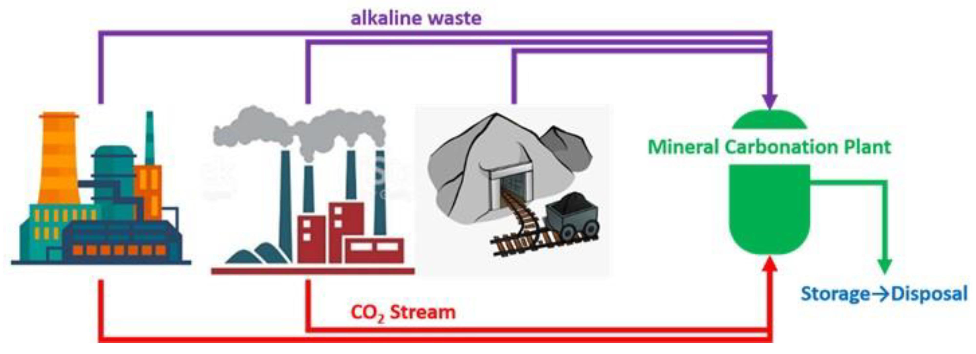
Some of the industrial wastes applicable for MC include coal fly ash, metallurgical slag, concrete wastes, mining and mineral processing wastes, and paper mill wastes [3,9,10,11,12,13,14,15,16,17,18,19]. As indicated above, although the quantity of available alkaline wastes is small compared to natural silicate minerals, they could fix a relevant amount of CO2 in some industries, particularly where CO2 and alkaline wastes are produced nearby. This could contribute to the possible de-carbonization of specific industrial sectors, such as the cement and metallurgical industries (Figure 1).

Figure 1.
Scheme of mineral carbonation process by a combination of CO2 emissions and industrial/mining alkaline wastes.
MC can be realized either in situ (underground in geologic formations), or ex situ (above ground in a chemical plant). The carbonation of industrial wastes is obviously accomplished ex situ, by ei-ther direct carbonation or indirect carbonation. Direct carbonation can be implemented via gas–solid reactions or in aqueous solutions [20,21]. Indirect carbonation methods involve previous extraction of reactive components (Mg2+ and Ca2+) by the utilization of acids or other solvents, followed by carbonation reactions [1,22].
A considerable amount of research in the literature has been devoted to the utilization of industrial wastes for MC under direct carbonation in an aqueous phase, while few works have been dedicated to gas–solid direct carbonation, as indicated in the review of Bobicki et al. [1].
In this work, the direct dry mineral carbonation of selected mining wastes, using carbon dioxide derived from combustion flue gas, was evaluated. Specifically, coal fly ash from two Australian brown coal-fired power plants, red mud from the refinement of bauxite into alumina, and diamond tailings were considered, due to their relevant residual alkali content. These materials were tested in a laboratory-scale fluidized bed reactor at different temperatures (300–450 °C), in a reactive environment that simulated the typical CO2 concentration of a combustion flue gas.
2. Materials and Methods
2.1. Materials
The following four different waste materials from the Australian mining and industrial sectors were tested to quantify their CO2 capture capacity: diamond tailings (DT), red mud (RM), Yallourn coal ash (YA), and Loy Yang coal ash (LYA). XRF analysis of the four as-received materials (on dry basis) is reported in Table 1. All materials present a large amount of inert compounds towards CO2, such as SiO2, aluminum-based, and iron-based compounds.

Table 1.
Results of the XRF analysis for the four samples. The values shown are in mass percentage (dry basis).
The amount of SiO2 is higher than 50% for LYA, but only 5% for YA. For this latter and for RM, the presence of iron-based compounds is relevant (~25–35%); for the others, the amount is lower than 10%. RM also has a relevant amount of aluminum-based compounds of about 20%, which is slightly lower for LYA (~13%), while it is only 3–5% for the other two materials. Of great importance is the presence of calcium-based compounds, which may represent the active phase for CO2 capture. Their presence fluctuates among the waste materials; YA presents the highest value at around 5%, followed by DT (4%), RM (2%), and LYA (1%). Notably, the sodium content is quite high in RM (~10%), while magnesium is high in DT (27%) and YA (13%).
Thermodynamic analysis (not reported here) on the components of the waste materials revealed that Ca-, Ba-, K-, Sr-, Mg- and Na-based minerals have the potential to react with CO2 in the temperature range of interest for a possible process of CO2 capture and sequestration. Specifically, all oxides of these components can carbonate at temperatures up to 500 °C, except for MgO, for which carbonation is only possible up to about 350 °C.
2.2. Thermogravimetric (TG) Characterization
Mass loss upon heating for the as-received materials was characterized in a LECO TGA701 thermogravimetric analyzer. About 1 g of material, sieved in the particle size range 300–600 µm, was used in each analysis. The samples were heated from 25 to 1000 °C at a constant heating rate of 7 °C/min in a nitrogen atmosphere.
2.3. Carbonation Test Apparatus
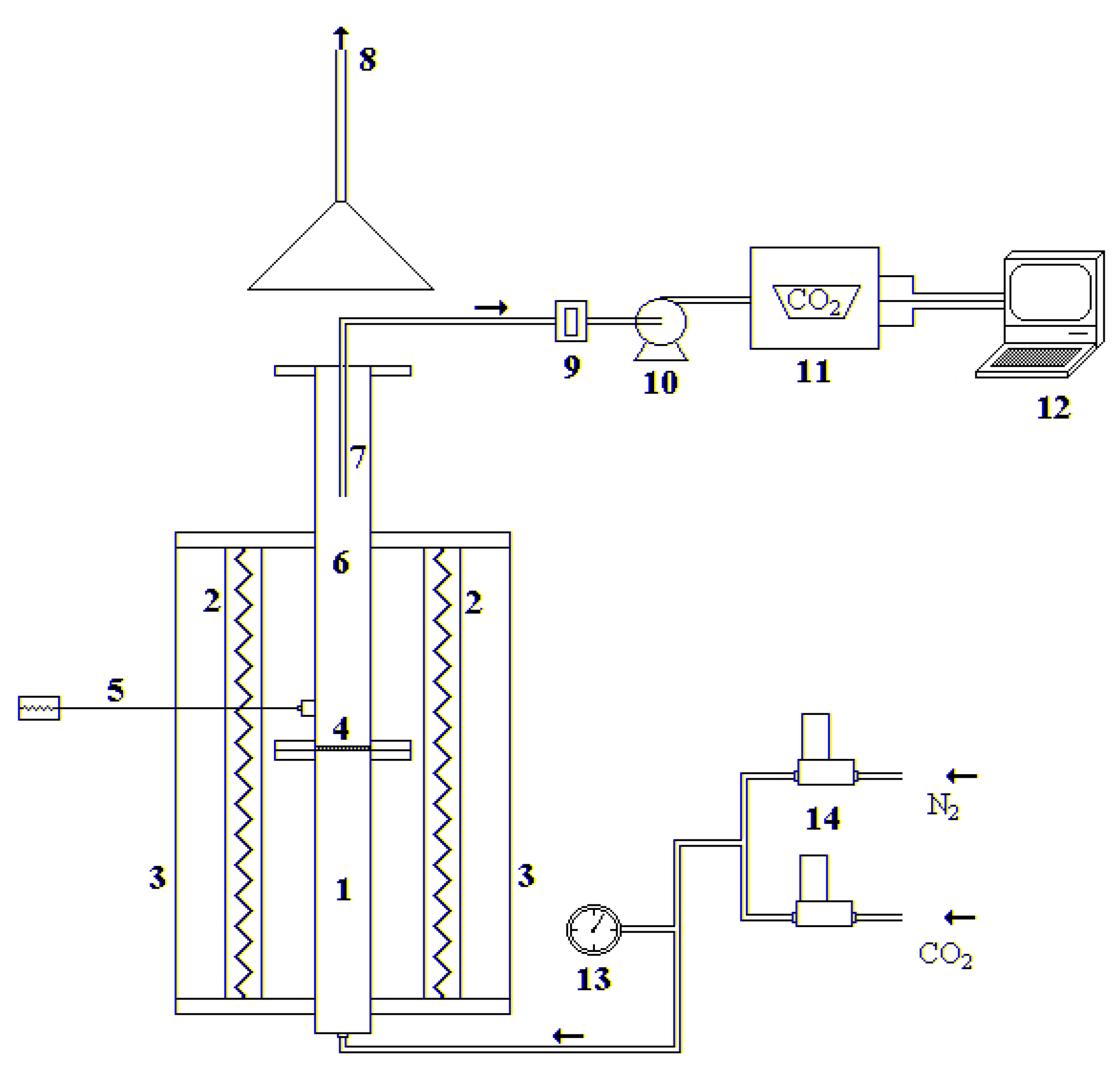
The experimental tests were carried out in a stainless-steel lab-scale fluidized bed reactor, electrically heated, with an internal diameter of 40 mm and a total height of 1.60 m, divided into a preheating/premixing section (0.65 m) and the fluidization column (0.95 m), as shown in Figure 2. The two sections are connected by a perforated distributor plate with 55 holes (hole diameter of 0.5 mm), arranged in a triangular pitch. The fluidization gases are sent to the reactor by the utilization of two mass flow controllers (Bronkhorst High Tech™, Ruurlo, The Netherlands). At the outlet of the reactor, the gas is sampled and sent to an NDIR analyzer, in order to follow the CO2 concentration profile, recorded with a frequency of 1 Hz through LABVIEW software.
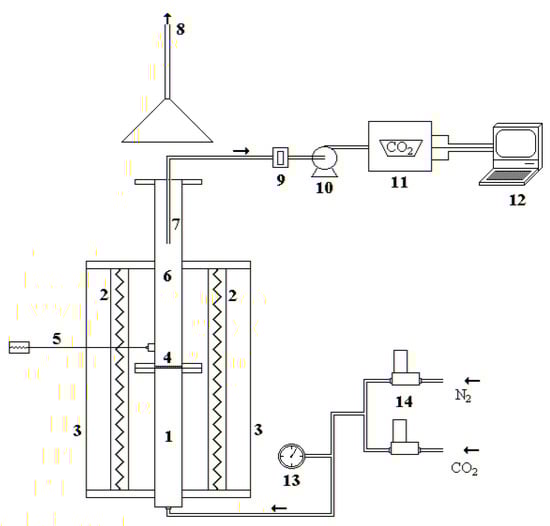
Figure 2.
Experimental fluidized bed apparatus: (1) gas preheating section; (2) electrical furnaces; (3) ceramic insulator; (4) gas distributor; (5) thermocouple; (6) fluidization column; (7) exhaust gas suction probe; (8) stack; (9) cellulose filter; (10) membrane pump; (11) gas analyzer; (12) personal computer; (13) manometer; (14) digital mass flowmeters.
2.4. Carbonation Test Procedure
For each test, the fluidized bed was loaded with 150 g of silica sand, adopted as buffer material, previously sieved in the particle size range 900–1000 µm, and then heated to the desired temperature inside the reactor.
The different waste materials were previously sieved in the particle size range 300–600 µm. The particle size difference between sand and waste material facilitated the separation of them by sieving at the end of the test.
In regards to the experimental procedure, all the samples were first subjected to a drying phase carried out in a muffle furnace at a temperature of 107 °C overnight. This procedure served to eliminate all the moisture present in the samples, in order to allow correct evaluation of the performance of the tested samples.
The tests were carried out at constant temperatures of 300, 350, 400, and 450 °C in a fluidizing atmosphere composed of 15% CO2 in nitrogen. The different temperatures were tested in order to find the best compromise between thermodynamics and kinetics that maximized the CO2 capture capacity. For each test, about 40 g of material was injected into the hot reactor, and the CO2 concentration evolution was continuously followed by the analyzer. Each test lasted for 10 min, a time sufficient to complete the carbonation reaction. Once the test was finished, it was possible to calculate the CO2 capture capacity of the material by analyzing the CO2 profile at the reactor outlet using the following formula:
where:
- = mass flow rate of CO2 entering the reactor;
- = mass flow rate of CO2 leaving the reactor, expressed as a function of time t;
- = mass of carbon dioxide captured;
- = mass of the sorbent initially used for the test.
2.5. XRD Analysis
As-received and selected tested samples (at 300 and 450 °C) were subjected to X-ray diffraction (XRD) characterization by means of a Philips X’Pert PRO apparatus (working radiation CuKα, anti-scatter silt width: 7.5 mm); the 2θ range of collected patterns was 5–80°, which was scanned using a step size of 0.013° and a scan speed of 0.156° s−1. Peak matching was carried out using the in-built software library. Table 2 summarizes the mineralogical identification for the as-received and tested samples.
Table 2.
Results of the XRD analysis for the four samples.
3. Results and Discussion
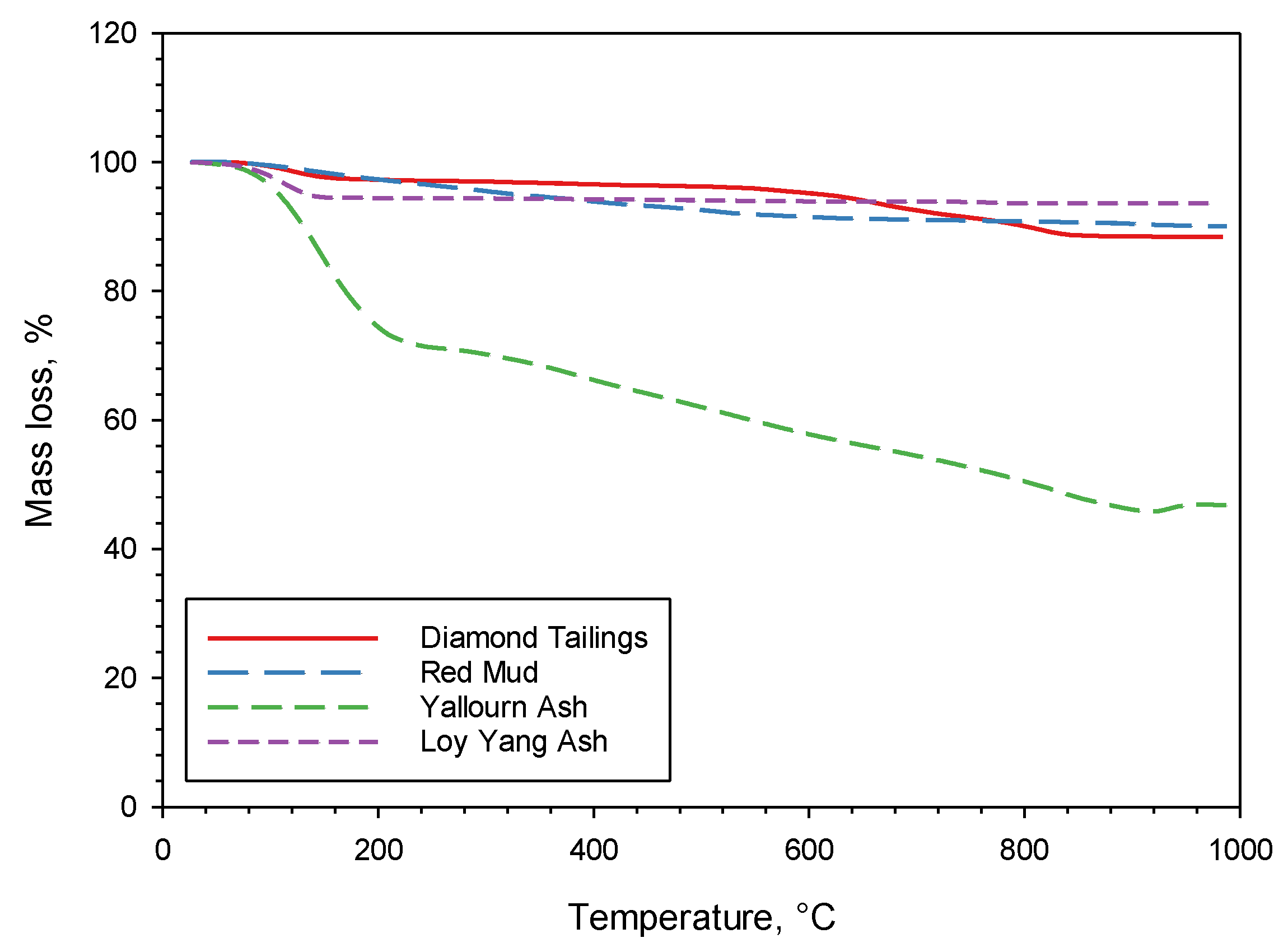
Figure 3 shows the TG mass loss data for the four as-received sorbents heated up to 1000 °C at 7 °C/min in nitrogen. The mass loss between 100 and 200 °C, visible for some of the sorbents (in particular, YA), is due to the removal of humidity and weakly bonded H2O. It is interesting to observe that above 200 °C, LYA has a negligible mass loss, DT and RM have a limited mass loss, while YA has a significant mass loss. These results are reflected in the loss on ignition (LOI—dry basis) data reported in Table 1. For RM, this mass loss occurs between 200 and 600 °C, and it is most likely attributable to the removal of strongly bonded H2O from the silicate structure. For DT, the loss occurs between 550 and 850 °C, and is attributable to calcite decomposition and serpentine (antigorite) breakdown. The large mass loss of YA is mostly connected to a release of H2O and CO2, and it is attributable to the removal of strongly bonded H2O and to carbonate decomposition. These results will be further discussed later, in connection to the outcomes of the carbonation tests and XRD analysis.
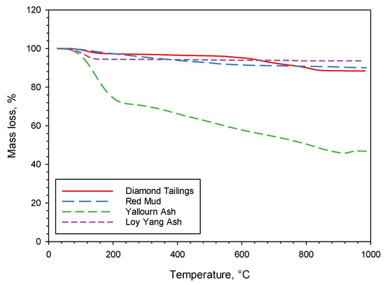
Figure 3.
Mass loss results of TG tests on the four sorbents.
Figure 4 reports the results of the carbonation tests carried out at the various selected temperatures (in the range 300–450 °C), which shows the measured capture capacity of the four samples, expressed in milligrams of captured CO2 per gram of sample initially fed to the reactor. In all the tests, the carbonation reaction was fast, and it was completed in 1–2 min. It is probable that a low-rate carbonation tail was still present after this first high-rate stage, but this could not be appreciated, due to the detection limit of the CO2 analyzer. Regardless, should it be present, it would have very limited practical relevance.
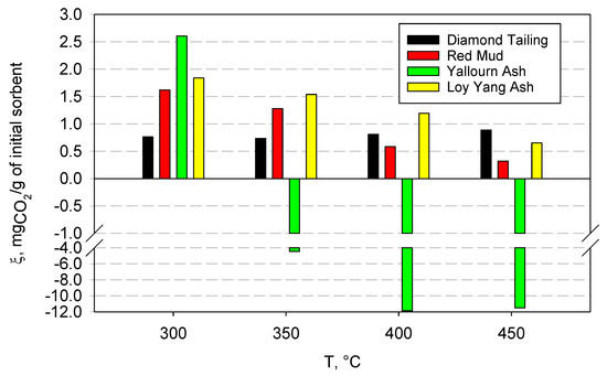
Figure 4.
CO2 capture capacity for the four samples at different temperatures, expressed as mg of captured CO2 per gram of initial sorbent.
As a general comment, the carbonation test results can be interpreted in light of the competition between the chemical kinetics of the carbonation reactions, which steadily increases with temperature, and chemical equilibrium thermodynamics. Since all carbonation reactions are exothermic, they are thermodynamically favored at low temperatures, while the reverse reaction (calcination) is favored at high temperatures. Which of these effects prevails in a certain temperature range depends on the chemical nature of the sample and on the specific carbonates that are formed upon reaction.
The DT samples showed a low capture capacity, with a slightly increasing trend with temperature; at 300 °C, the capture capacity was equal to 0.76 mgCO2/g, while, at 350 °C, it decreased slightly. For higher temperatures, however, the capture capacity increased, reaching a value of 0.89 mgCO2/g at 450 °C. This trend can be justified by observing that as the temperature increases, the reaction is gradually disadvantaged from a thermodynamic point of view, but the chemical kinetics increases, and transport phenomena as well. This increase seems to compensate for the worsening thermodynamic conditions, and translated into an overall increase in capture capacity as the temperature increased.
The XRD analysis on the raw DT sample (Table 2) showed that it was made up of mixed silicates of magnesium, iron, aluminum, calcium, and potassium. Moderate amounts of quartz and calcite were also detected. Such an analysis is consistent with the typical kimberlite nature of diamond tailings [23].
After the carbonation tests, the XRD analysis confirmed the silicate nature of the sample. At the same time, a larger amount of calcium carbonate (calcite) was detected in the samples, while no other carbonates were detected. Based on these observations, the most likely reaction occurring during the tests is the attack of CO2 to calcium contained in the silicates, forming separate calcium carbonate. Such a carbonation mechanism is different from that reported for wet conditions, where magnesium carbonates have been detected as the main product species [23], but it is consistent with the well-known evidence that magnesium species do not react significantly with CO2 in dry conditions at atmospheric pressure [4].
Contrary to the above results, the RM samples show a larger capture capacity and a decreasing trend with temperature. In this case, the maximum capture capacity value was found at 300 °C, and it was equal to 1.62 mgCO2/g, while, as the temperature increased, a lower value was recorded, down to the minimum value of 0.32 mgCO2/g at 450 °C.
An XRD analysis on the raw RM sample (Table 2) indicated iron oxide (hematite), mixed silicates (of sodium, aluminum, calcium, magnesium, and iron), titanium oxide (anatase), and a small amount of boehmite as the crystalline phases. After the carbonation tests, the XRD analysis of the samples was very similar to that of the raw sample, while a sodium aluminum silicate carbonate was clearly detected (Na7.6(Al6Si6O24)(CO3)0.93(H2O)2.93). This suggests that the sodium aluminum silicate is able to directly react with CO2 to form a stable carbonate. A small amount of dolomite was also detected, indicating that calcium and magnesium were also able to capture CO2.
The observed capture trend is most likely ascribable to the action that thermodynamics performs on the carbonation reaction. In fact, unlike the DT samples, where the capture capacity increased with temperature, in this case, it decreased because, despite the fact that high temperature favors kinetics, it also disfavors thermodynamics of the exothermic carbonation reaction. Indeed, the sodium aluminum silicate present in the RM samples is close to the threshold temperature, beyond which the inverse calcination reaction is known to take place [4]. Hence, its ability to react with CO2 becomes progressively depressed as the temperature increases.
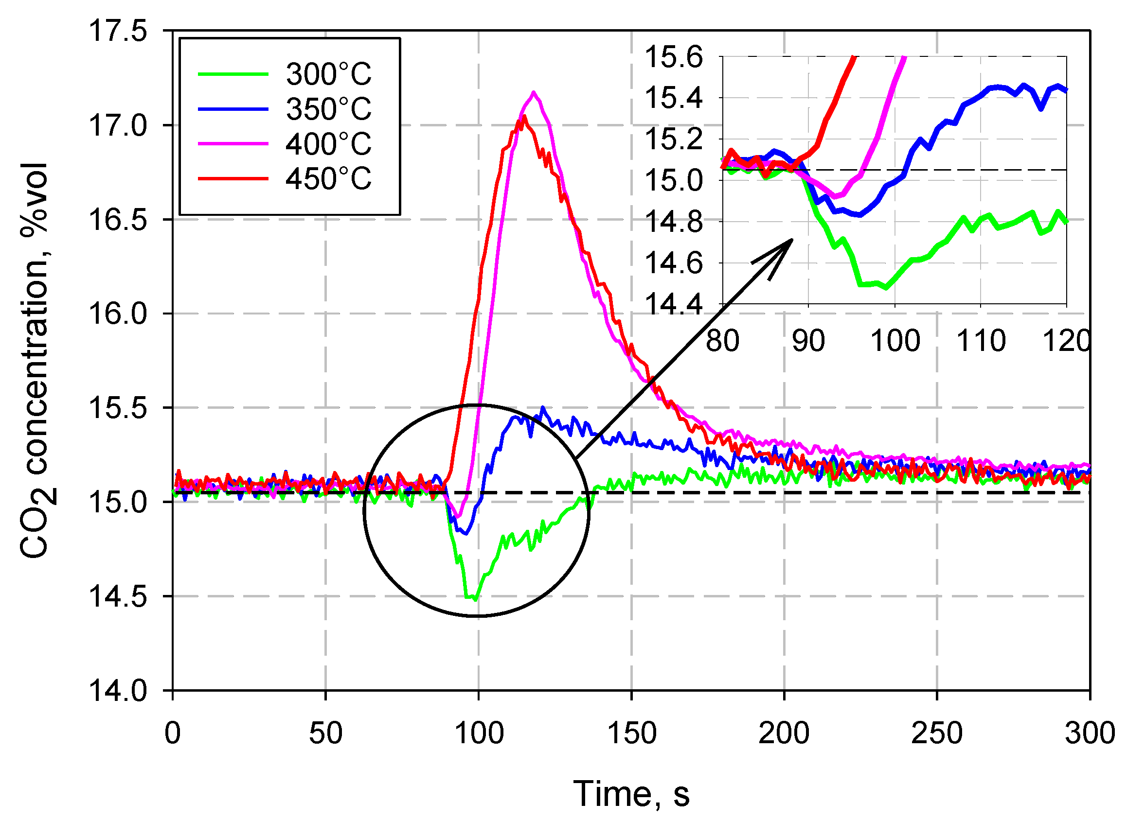
YA exhibited a singular behavior during the tests; CO2 capture was only recorded at 300 °C, while, starting from 350 °C, the sorbent began to release CO2, rather than absorb it. This can be clearly observed in Figure 5, which shows the CO2 concentration profiles measured during the tests at the different investigated temperatures (it must be remembered that the feed gas was composed of 15% CO2 and 85% N2 in volume).
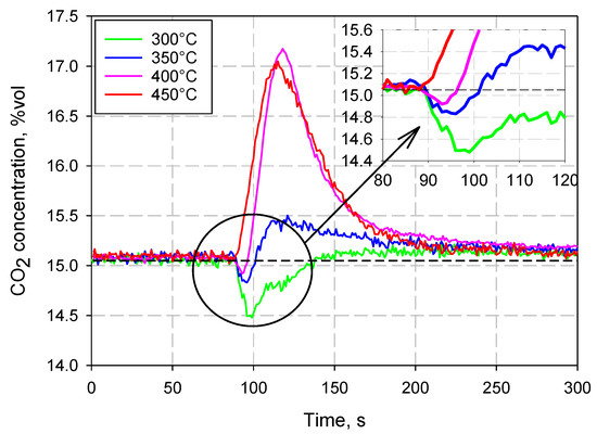
Figure 5.
Outlet CO2 concentration profiles at different temperatures for Yallourn coal ash.
The XRD analysis on the raw YA sample (Table 2) indicated iron oxide (magnetite), mixed oxides (of magnesium, calcium, aluminum, and iron—mainly magnesioferrite (MgFe2O4)), quartz, and calcium aluminum carbonate (hydrocalumite) as the crystalline phases. YA has quite a different composition to typical coal ash, depending on the peculiar location of the lignite quarry in Australia, and it is well known to be uniquely rich in magnesioferrite [24,25]. After the carbonation tests, the XRD analysis of the samples showed, as the crystalline phases, the same species as for the raw sample, except for the presence of calcium carbonate (calcite).
The behavior observed in the experiments can be explained by assuming that the material had already undergone carbonation before the tests, probably because it was exposed to the atmosphere for a long time. In fact, in contact with air, the so-called weathering reactions can occur, which consist of the slow reaction of the metal oxides contained in the material with the CO2 present in the atmosphere. This results in a dramatic reduction in the material’s capacity to capture CO2. In fact, YA, for temperatures above 300 °C, began to calcinate, releasing CO2, rather than capturing it. It is also interesting to note that, before the release of CO2 occurs, a small amount of absorption of carbon dioxide was still observed (see the insert in Figure 5), up to a temperature of 400 °C. At 450 °C, however, this phenomenon was no longer observable. It can, therefore, be assumed that a significant part of the oxides present in YA was already carbonated, due to the weathering reactions, and that, starting from 350 °C, sufficiently high temperatures were reached to favor, at least partially, calcination reactions, which involve the release of carbon dioxide.
LYA shows a decreasing trend of the capture capacity with temperature, similar to what was observed for the RM sample, which can also be justified by observing that carbonation is an exothermic reaction, and that it, therefore, becomes thermodynamically unfavorable as the temperature increases and the calcination temperatures are approached. In this case, unlike YA, there is no release of carbon dioxide, but always a small amount of CO2 capture. This suggests that this ash was not partly carbonated due to weathering reactions.
The XRD analysis on the raw LYA sample (Table 2) indicated the crystalline phases as quartz, iron oxide (hematite), calcium aluminum silicate, mixed sodium, magnesium, and aluminum sulfates, and small quantities of titanium oxide. After the carbonation tests, the XRD analysis of the samples showed, as the crystalline phases, the same species as for the raw sample, plus calcium carbonate (calcite) and calcium magnesium carbonate (dolomite), which appear to be the only stable products of carbonation.
4. Conclusions
Four different waste materials from the Australian mining and industrial sectors were tested to quantify their CO2 capture capacity under dry carbonation conditions. Specifically, coal fly ash from two brown coal-fired power plants, red mud from the refinement of bauxite into alumina, and diamond tailings were considered, due to their relevant residual alkali content. The experimental campaign was performed in a lab-scale fluidized bed reactor at different temperatures (300–450 °C), simulating the typical CO2 concentrations in a combustion flue gas, and complemented by TG and XRD analyses.
The results indicated a low, but non-negligible, CO2 capture capacity for three of the materials tested, which appears to be more favorable in the lower temperature range, and with relatively fast kinetics. The diamond tailings were the only material to show a slightly increasing capture capacity with temperature, while all the other materials performed worse when the temperature increased, because of increasing thermodynamic limitations. One fly ash exhibited a different behavior, releasing CO2 above 350 °C, rather than capturing it. This behavior was explained by the extensive weathering of the fly ash before the tests.
It should be noted that, while the capture capacity of the materials tested in this study is low in comparison to other published data (values as high as 520 mgCO2/g have been reported [1]), the availability of these materials at a large scale and their potential applications in mine reclamation make the case for further research and indicate the possible practical viability of this approach at industrial scales. In addition, the mining industries’ targets to achieve net-zero emissions, and the financial liabilities associated with mining waste management and mine rehabilitation, could overcome the economic drawbacks of mineral carbonation applications in the mining industry.
Author Contributions
Conceptualization, methodology and investigation, F.S. and A.C.; data curation, A.C.; writing—original draft preparation, F.S.; writing—review and editing, M.A.; supervision, F.S. and M.A. All authors have read and agreed to the published version of the manuscript.
Funding
This research received no external funding.
Data Availability Statement
The data presented in this study are available on request from the authors.
Acknowledgments
The help of Francesco Pizzo, Alessandro Esposito, Laura Ricci, Serena Andrisani, Ilenia Menditto, and Valentina Catapano in performing the experimental campaign is gratefully acknowledged.
Conflicts of Interest
The authors declare no conflict of interest.
References
- Bobicki, E.R.; Liu, Q.; Xu, Z.; Zeng, H. Carbon capture and storage using alkaline industrial wastes. Prog. Energy Combust. Sci. 2012, 38, 302–320. [Google Scholar] [CrossRef]
- Wang, F.; Dreisinger, D.B.; Jarvis, M.; Hitchins, T. The technology of CO2 sequestration by mineral carbonation: Current status and future prospects. Can. Met. Q. 2018, 57, 46–58. [Google Scholar] [CrossRef] [Green Version]
- Huijgen, W.J.J.; Comans, R.N.J. Carbon Dioxide Sequestration by Mineral Carbonation; Literature Review ECN-C-03-016; Energy Research Centre: Wageningen, The Netherlands, 2003. [Google Scholar]
- Lackner, K.S.; Wendt, C.H.; Butt, D.P.; Joyce, E.L., Jr.; Sharp, D.H. Carbon dioxide disposal in carbonate minerals. Energy 1995, 20, 1153–1170. [Google Scholar] [CrossRef]
- Doucet, F.J. Scoping Study on CO2 Mineralization Technologies; Contract report No CGS-2011-007; Council for Geoscience: Pretoria, South Africa, 2011. [Google Scholar]
- Huijgen, W.J.J.; Witkamp, G.-J.; Comans, R.N.J. Mineral CO2 Sequestration by Steel Slag Carbonation. Environ. Sci. Technol. 2005, 39, 9676–9682. [Google Scholar] [CrossRef] [PubMed]
- Goldberg, P.; Chen, Z.-Y.; O’Connor, W.; Walters, R.; Ziock, H. CO2 mineral sequestration studies in the US. In Proceedings of the First National Conference on Carbon Sequestration, Washington, DC, USA, 14–17 May 2001. [Google Scholar]
- Sanna, A.; Uibu, M.; Caramanna, G.; Kuusik, R.; Maroto-Valer, M.M. A review of mineral carbonation technologies to sequester CO2. Chem. Soc. Rev. 2014, 43, 8049–8080. [Google Scholar] [CrossRef] [PubMed] [Green Version]
- Gerdemann, S.J.; O’Connor, W.K.; Dahlin, D.C.; Penner, L.R.; Rush, H. Ex situ aqueous mineral carbonation. Environ. Sci. Technol. 2007, 41, 2587–2593. [Google Scholar] [CrossRef] [PubMed]
- Su, T.-H.; Yang, H.-J.; Shau, Y.-H.; Takazawa, E.; Lee, Y.-C. CO2 sequestration utilizing basic-oxygen furnace slag: Controlling factors, reaction mechanisms and V–Cr concerns. J. Environ. Sci. 2016, 41, 99–111. [Google Scholar] [CrossRef] [PubMed]
- Polettini, A.; Pomi, R.; Stramazzo, A. Carbon sequestration through accelerated carbonation of BOF slag: Influence of particle size characteristics. Chem. Eng. J. 2016, 298, 26–35. [Google Scholar] [CrossRef]
- Dananjayan, R.R.T.; Kandasamy, P.; Andimuthu, R. Direct mineral carbonation of coal fly ash for CO2 sequestration. J. Clean. Prod. 2016, 112, 4173–4182. [Google Scholar] [CrossRef]
- Mayoral, M.C.; Andrés, J.M.; Gimeno, M. Optimization of mineral carbonation process for CO2 sequestration by lime-rich coal ashes. Fuel 2013, 106, 448–454. [Google Scholar] [CrossRef]
- Hosseini, T.; Haque, N.; Selomulya, C.; Zhang, L. Mineral carbonation of Victorian brown coal fly ash using regenerative ammonium chloride–Process simulation and techno-economic analysis. Appl. Energy 2016, 175, 54–68. [Google Scholar] [CrossRef]
- Nyambura, M.G.; Mugera, G.W.; Felicia, P.L.; Gathura, N.P. Carbonation of brine impacted fractionated coal fly ash: Implications for CO2 sequestration. J. Environ. Manag. 2011, 92, 655–664. [Google Scholar] [CrossRef] [PubMed]
- Han, S.-J.; Im, H.J.; Wee, J.-H. Leaching and indirect mineral carbonation performance of coal fly ash-water solution system. Appl. Energy 2015, 142, 274–282. [Google Scholar] [CrossRef]
- Reynolds, B.; Reddy, K.J.; Argyle, M.D. Field Application of Accelerated Mineral Carbonation. Minerals 2014, 4, 191–207. [Google Scholar] [CrossRef] [Green Version]
- Kasina, M.; Kowalski, P.R.; Michalik, M. Mineral carbonation of metallurgical slags. Minerals 2015, 45, 27–45. [Google Scholar] [CrossRef] [Green Version]
- Santos, R.M.; François, D.; Mertens, G.; Elsen, J.; Van Gerven, T. Ultrasound-intensified mineral carbonation. Appl. Therm. Eng. 2013, 57, 154–163. [Google Scholar] [CrossRef] [Green Version]
- Kwak, J.H.; Hu, J.Z.; Turcu, R.V.; Rosso, K.M.; Ilton, E.S.; Wang, C.; Sears, J.A.; Engelhard, M.H.; Felmy, A.R.; Hoyt, D.W. The role of H2O in the carbonation of forsterite in supercritical CO2. Int. J. Greenh. Gas Control 2011, 5, 1081–1092. [Google Scholar] [CrossRef]
- Kwak, J.H.; Hu, J.Z.; Hoyt, D.W.; Sears, J.A.; Wang, C.; Rosso, K.M.; Felmy, A.R. Metal Carbonation of Forsterite in Supercritical CO2 and H2O Using Solid State 29Si, 13C NMR Spectroscopy. J. Phys. Chem. C 2010, 114, 4126–4134. [Google Scholar] [CrossRef]
- Eloneva, S.; Said, A.; Fogelholm, C.-J.; Zevenhoven, R. Preliminary assessment of a method utilizing carbon dioxide and steelmaking slags to produce precipitated calcium carbonate. Appl. Energy 2012, 90, 329–334. [Google Scholar] [CrossRef]
- Chakravarthy, C.; Chalouati, S.; Chai, Y.E.; Fantucci, H.; Santos, R.M. Valorization of Kimberlite Tailings by Carbon Capture and Utilization (CCU) Method. Minerals 2020, 10, 611. [Google Scholar] [CrossRef]
- Choo, T.K.; Song, Y.; Zhang, L.; Selomulya, C.; Zhang, L. Mechanisms Underpinning the Mobilization of Iron and Magnesium Cations from Victorian Brown Coal Fly Ash. Energy Fuels 2014, 28, 4051–4061. [Google Scholar] [CrossRef]
- Xu, T.; Bhattacharya, S. Mineral Transformation and Morphological Change during Pyrolysis and Gasification of Victorian Brown Coals in an Entrained Flow Reactor. Energy Fuels 2019, 33, 6134–6147. [Google Scholar] [CrossRef]

Publisher’s Note: MDPI stays neutral with regard to jurisdictional claims in published maps and institutional affiliations. |
© 2022 by the authors. Licensee MDPI, Basel, Switzerland. This article is an open access article distributed under the terms and conditions of the Creative Commons Attribution (CC BY) license (https://creativecommons.org/licenses/by/4.0/).