Article

Investigations of Middle-Caliber Anti-Aircraft Cannon Interior Ballistics including Heat Transfer Problem in Estimation of Critical Burst Length

Faculty of Mechatronics, Armament and Aerospace, Military University of Technology, 2 Sylwestra Kaliskiego Street, 00-908 Warsaw, Poland
*
Author to whom correspondence should be addressed.
Processes 2022, 10(3), 607; https://doi.org/10.3390/pr10030607
Submission received: 25 February 2022 / Revised: 10 March 2022 / Accepted: 18 March 2022 / Published: 20 March 2022
(This article belongs to the Special Issue Advances in CFD Analysis of Convective Heat Transfer)

Abstract

:
Numerical and experimental investigations of armament systems are an important part of modern design processes. The presented paper reports problems that were encountered on the theoretical analysis of the performance of 35 mm anti-aircraft cannon and the way in which they were solved. The first problem concerns the application of results of closed vessel tests of used propellant in interior ballistics simulations. The use of a nonstandard form of the gas generation rate equation solved this problem. The second problem concerned the assessment of projectile–barrel interaction. The barrel resistance was estimated making use of finite element analysis. The third problem arose from the need to determine the heat transfer from propellant gases to the barrel. The employed formula for the heat exchange coefficient and 2D modelling of the heat conduction in the barrel provided the solution. Selected elements of the theoretical model were validated by shooting range experiments and data provided by the ammunition producer. Using the considered approach, crucial ballistic parameters (maximum propellant gas pressure and muzzle velocity) were estimated with an error of less than 6.0%, without application of additional fitting coefficients. The numerical estimation of the barrel external surface temperature provided a relative discrepancy with the experimental data lower than 6% and enabled the estimation of the critical burst length, equal to 14 shots.

1. Introduction

Numerical and experimental investigations of interior ballistics phenomena are an important part of modern armament design and the modernization process [1,2]. Results of these works provide the set of data, necessary in mechanical and thermal examinations of the under-investigation construction. Taking into account the limited number of reports considering the middle-caliber gun (in the literature small arms and large-caliber guns, e.g., 120 mm, were mainly considered), the aim of this paper is to present the problems that the authors encountered on the theoretical analysis of the performance of 35 mm anti-aircraft cannon and the way in which they were solved. The first problem was connected with the characteristics of single-base propellant applied in the under-consideration launching system. To obtain realistic values of these characteristics closed vessel tests were performed. Their results enabled us to apply a nonstandard form of the gas production equation for the interior ballistics simulations. In the simulations, the thermodynamic lumped-parameter model of interior ballistics was applied. Many papers provide data which confirm correctness and efficiency of such a modeling way (e.g., [3,4,5,6,7]).
The second problem concerned the assessment of the interaction between the projectile and the barrel. In the classical approach [3] the proportionality between the projectile kinetic energy and the resistance work is assumed. This problem for artillery systems was investigated theoretically more thoroughly by several scientific teams, e.g., [7,8,9,10]. Authors of [7] investigated numerically the influence of bore wear on the course of barrel resistance force. In this model, the discussed force was included in the fictionally increased projectile mass. As the result of FEA simulations, the influence of barrel bore length and land height were estimated. It was concluded in [8] that, due to the large number of parameters impacting on the barrel resistance force course, it is necessary to conduct simulations of the projectile–barrel interaction for each investigated system. In paper [9] the authors investigated the influence of the implemented computational method on the results of simulations of the rotating band engraving process. All three considered methods, i.e., Lagrangian finite element approach (FEM), meshless method (FEM-SPH), and Lagrangian–Eulerian approach (CEL), provided similar results. Authors of [10] investigated the influence of propellant charge mass on the barrel resistance force. As stated, the pressure course has significant influence on the value of the investigated force. Moreover, the qualitative course of resistance is similarly independent from the propellant charge mass. Similar conclusions can be found in [11], where this effect was explained mainly by the Poisson effect. All cited works showed that for the realistic assessment of the resistance force finite element simulations are necessary. This way was chosen in this paper.
The third problem relates to the theoretical assessment of the critical burst length. Calculations of the temperature distribution in the barrel are necessary for this assessment. A relevant formula for calculation of the heat exchange coefficient value was chosen and 2D/3D heat conduction simulations were performed.
To validate the accepted solutions of the mentioned problems, experimental shooting tests were performed. The producer’s ammunition data and measurements of the projectile muzzle velocity allowed for validation of the interior ballistics model and the method of assessment of the resistance force. Application of thermography provided data for estimation of the thermal model correctness.

2. Experimental Investigations

2.1. Propellant Characteristics

Experimental investigations of propellant characteristics were based on classical closed vessel tests [12]. Propellant gas pressure courses were provided making use of a 200 cm3 closed vessel HPI B180T (HPI, Austria) presented in Figure 1. The gas pressure value was measured using an HPI 5QP6000M piezoelectric transducer (HPI, Austria), characterized by a maximum measurement error of 1%.
The considered propellant was a single-base one and its grains (shown in Figure 2) were characterized by dimensions summarized in Table 1.
In order to estimate the required characteristics, tests were conducted in conditions of two values of loading density, i.e., 100 kg/m3 and 200 kg/m3. For each condition, two tests were carried out. Pressure courses provided by these experiments are presented in Figure 3.
Using the methodology of heat losses correction described in [12,13], where losses are estimated using the descending part of the pressure curve to assess the heat transfer coefficient, the corrected values and courses were obtained. To correct the pressure curve, the values of correction for each measured value should be calculated:
Δ p ( t ) = 1 t r t i g n t p ( τ ) d τ
where p is pressure, t—time, tr—resultant characteristic time of pressure decrease, tign—ignition time of propellant bed. The applied tr constant can be assessed using the following formula:
t r = t max t d p ( t ) d t p max p d
where pmax is the maximum pressure, pd is a certain value on the descending part of the pressure curve (assumed value was equal to 0.6 pmax), tmax and td denote the time corresponding to the mentioned values of pressure.
The obtained maximum values of pressure (for the gas density characteristic for a completely burnt propellant) enabled assessment of the equation of state (EOS) coefficients using the least-squares approximation. In the presented considerations, the EOS, whose source is the Noble–Abel equation, was applied [3,4]:
p g ( ρ g ) = R g T g ρ g 1 α ρ g
where Rg is the individual gas constant, Tg—gas temperature, ρg—gas density, α—co-volume coefficient. The estimated values of the EOS coefficient are summarized in Table 2. The letters E and Q denote the values obtained from uncorrected (E) and corrected for heat loss experimental data. In further investigations, the second set of data was applied.
In the above-presented table, Tg0 means the flame temperature of burning propellant.
Assuming the following burning law:
d z d t = G ( z ) p a t m ( p g p a t m ) n
where z denotes the relative burnt mass of propellant, t is time, G(z) is the dynamic vivacity function, patm is the atmospheric pressure, pg is the propellant gases pressure and n is the law exponent; it is possible to estimate the dynamic vivacity function course and the burning law exponent [13]. In the presented paper this was performed making use of the manipulated Equation (4):
log 10 ( d z d t ) = log 10 ( G ( z ) p a t m ) + n log ( p g p a t m )
Using values of dz/dt and pg for discrete values of z in the interval between 0.3 and 0.8, it is possible to estimate pressure exponent value n making use of the linear regression for each value of z. The estimated average value of n was equal to 0.961. The dynamic vivacity course as the function of relative burnt propellant mass was evaluated using Equation (4) and is presented in Figure 4. The first period of the burning process is seriously disturbed by different course of the ignition process in closed vessel conditions in comparison with ammunition. To minimalize this influence, the first segment of the G(z), curve was approximated by linear function (red line).
The values of dz/dt as a function of z and pg can be calculated using the relations:
d z / d t = ( d z / d p g ) ( d p g / d t )
z = b 1 p s f + b 2 p s , p s = p g p i g n , b 1 = 1 Δ 1 ρ g , b 2 = α 1 ρ g
where pign is the pressure generated by the ignition system and Δ is the loading density.
Pressure time derivative values are calculated based on the recorded pressure courses.

2.2. Ballistics Characteristics

Ballistics characteristics needed for validation of the theoretical model were determined during in-field shooting. Test were carried out using the measurement set presented in Figure 5. Applied Doppler radar Weibel SL-525PE (Weibel, Lillerød, Denmark) and the high-speed camera Phantom v1612 (Vision Research, Wayne, New Jersey, USA) allowed for measurements of muzzle velocity, which was estimated based on 7 rounds. Doppler radar was located at the cannon. In accordance with the producer’s data and known discrepancy between muzzle velocity and the value extrapolated to the muzzle using Doppler radar data (from external ballistics region), the maximum error of the muzzle velocity estimation can be equal to 1%, which results in approximately 10 m/s overestimation for the considered velocity range. In order to minimize the measurement error, the high-speed camera was positioned 15 meters from the muzzle (perpendicular to the barrel axis). Additional application of the thermographic camera FLIR E60 (FLIR, Wilsonville, Oregon, USA) was used to measure the temperature increase of the external barrel wall surface. Supplementary tests conducted in laboratory conditions allowed for estimation of temperature measurement accuracy of the applied approach. Comparison with values registered by the K-type thermocouple provided maximum discrepancy with the thermographic method equal to 2 °C for the under-investigation temperature range (15–50 °C). For all registered values, the thermographic results were overestimated, but the temperature differences were characterized by a lower value of uncertainty. Field measurements were carried out in a burst regime of fire, i.e., 6-round bursts from a distance of 3 m. To improve the correctness of measurements, a linear gauge was applied in the FLIR software. For each burst, the resultant temperature increase was estimated, which enabled the estimation of the mean temperature changes for each shot. To provide data for the validation of the theoretical model, the temperature increase of the selected barrel region (Figure 6) was estimated.
The conducted experimental investigations provided data of the projectile muzzle velocity. Results of measurements conducted using the high-speed camera and Doppler radar are summarized in Table 3. The results obtained using the camera confirm the correctness of the radar measurements, which were applied in the model validation.
After the experimental investigations of the projectile velocity for single shots, measurements of the increase of the barrel temperature for the burst fire were carried out. Exemplary temperature distribution on the barrel external surface is presented in Figure 7. The values of changes of temperature for the applied gauge are summarized in Table 4.

3. Numerical Simulations

Considered in this paper model of interior ballistics is the lumped-parameters model [14], based on the thermodynamic approach to modelling interior ballistics phenomena. In comparison with the classical approach, presented in [3], the model includes the explicit form of secondary works carried out by propellant gases. This fact forced the necessity to estimate the barrel resistance force, which was assessed in a numerical way.

3.1. Interior Ballistics Model

The model is represented by the set of ordinary differential equations, expressing the fundamental conservation laws:
  • Projectile trajectory equation:
    v p = d l p d t
    where vp is the projectile velocity, lp is its displacement, t stands for time.
  • Projectile equation of motion [4]:
    d v p d t = ( p p p b r p a i r ) s p m p
    where pp is the propellant gas pressure acting on the projectile base, pbr is the barrel resistance pressure, pair is the pressure of air compressed in front of the projectile, sp is the projectile cross-section area and mp is the projectile mass.
Due to the existence of gas pressure gradient, the value of pressure acting on the projectile base was estimated making use of the following relation [4]:
p p = p g + ( ω ( p b r + p a i r ) 3 m p ) / ( 1 + ω 3 m p )
where pg is the average propellant gas pressure and ω is the propellant mass.
The pressure of air in front of the projectile, pair, was estimated using the following relation [14]:
p a i r = p a t m + v p 2 ρ 0 γ a i r + 1 4 + v p 4 ρ 0 2 ( γ a i r + 1 4 ) 2 + v p 2 γ a i r ρ 0 p a t m
where ρ0 is the initial air density and γair is the air heat capacity ratio.
  • Propellant gases generation rate equation (4).
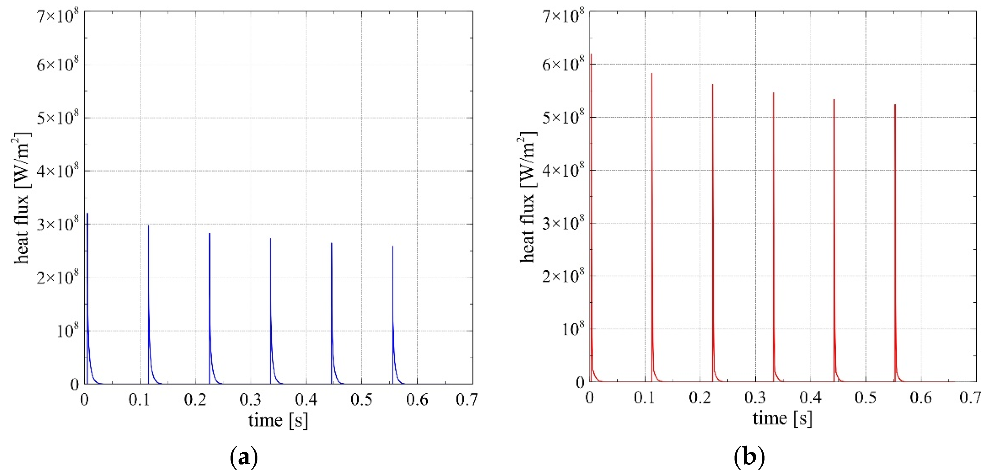
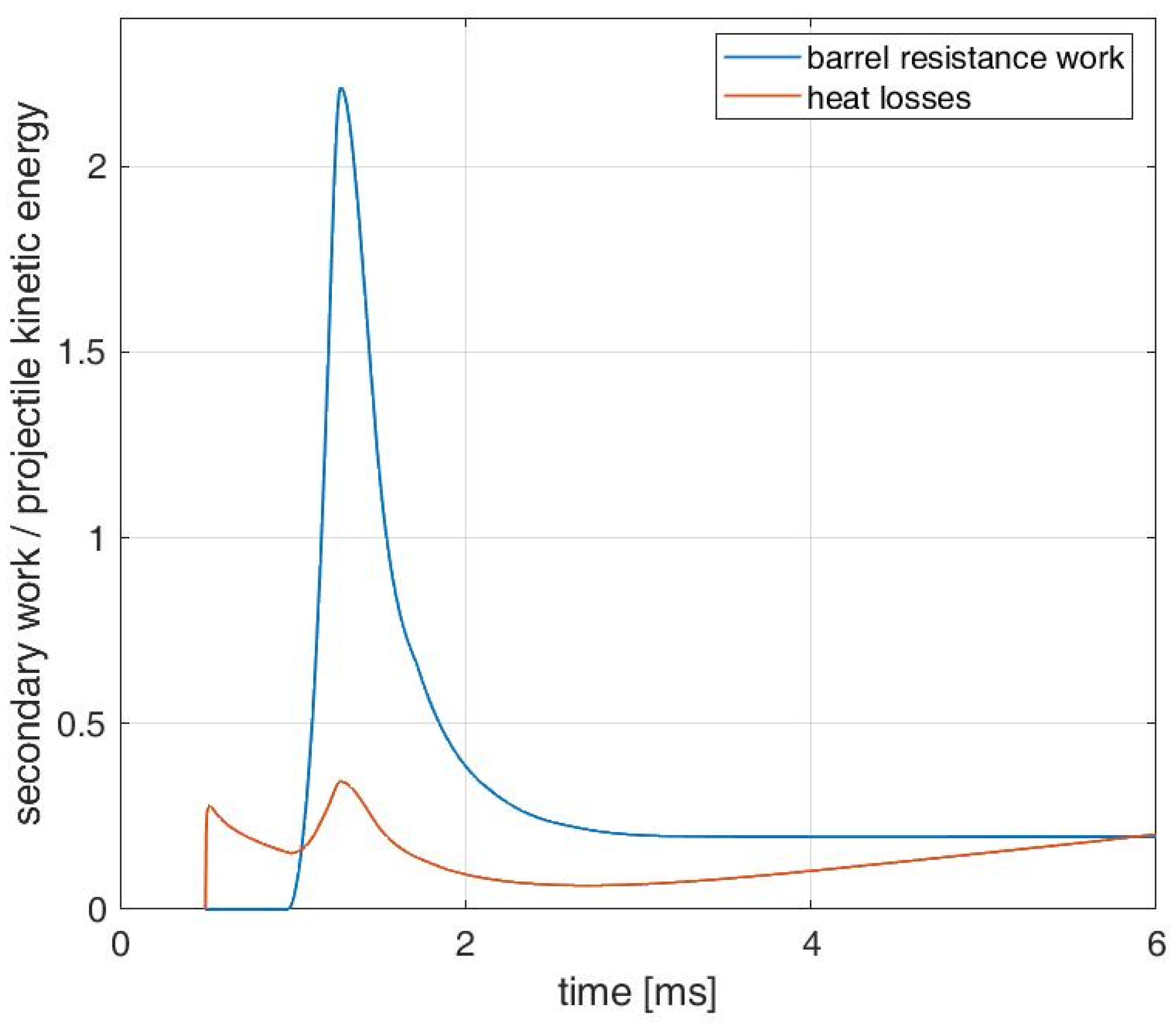
  • Equation defining the gas temperature changes rate [14]:
    d T g d t = ω d z d t ( q p o w c v g T g ) + ( c v g ω + c v a i r m a i r ) T g d ξ d t d W s u m d t d H o u t d t c v g ω ( z ξ ) + c v a i r m a i r ( 1 ξ )
    where Tg is the propellant gases temperature, ω is the propellant mass, qpow is the isochoric heat of combustion, cvg denotes the specific heat of propellant gases at constant volume, Wsum is the total work made by gases, ξ is the relative mass of outflowed gases, mair is the mass of air initially present in the case, cvair is the air specific heat at constant volume, Hout is the enthalpy of outflowing gases. Moreover, the following differential equations describing the enthalpy of outflowing gases were applied [14]:
    d H o u t d t = ( c p g ω + c p a i r m a i r ) T g d ξ d t
    where cpg and cpair are the specific heat of the propellant gases and air at constant pressure, respectively. The rate of change of the total work made by gases was expressed by the following differential equation:
    d W s u m d t = d E k i n d t + d W b r d t + d W a i r d t + d W t e r m d t
    where Ekin is the total kinetic energy of projectile and propellant-gas mixture, Wbr is the work done against barrel resistance, Wair is the work done against the pressure of air in front of the projectile, Wterm is the heat losses. The above-described change rates can be estimated by the following formulae [3,4,14]:
    d E k i n d t = ( I p 4 π 2 η 2 + m p + ω 3 ) v p d v p d t
    d W b r d t = s p p b r v p
    d W a i r d t = s p p a i r v p
    d W t e r m d t = s int h t e r m ( T g T b s ) d s
    where Ip is the projectile moment of inertia, η denotes the rifling twist, sint is the heat exchange surface, hterm is the heat transfer coefficient, Tbs is the barrel internal wall temperature. The heat transfer coefficient was estimated using the form of approximation available in the literature for pipe interior flows [15,16]:
    h t e r m ( x , t ) = 0.023 Re 0.8 Pr 0.3
    Re = ρ g a s v g a s d b μ g a s
    where x is the axial coordinate, db denotes barrel internal diameter, µgas is the dynamic viscosity coefficient of propellant gases, vgas is the propellant gases velocity.
Coefficients of the above-mentioned expression were estimated making use of the approximate propellant gases composition, summarized in Table 5 [17,18]. Diffusive transport coefficients were assessed using the molar fraction weighted averaging of the temperature functions of the dynamic viscosity and thermal conductivity of pure species. Estimated functions are presented in Figure 8 [18].
In order to include the internal barrel wall temperature changes, the two-dimensional Fourier–Kirchhoff equation was solved:
T b ( x , r , t ) t = 1 c b ρ b ( 1 r r ( λ b r T r ) + x ( λ b T x ) )
where Tb is the barrel material temperature, r is the radial coordinate, λb denotes the barrel material thermal conductivity, cb is the specific heat and ρb denotes the barrel material density.
The above-presented equation was supplemented by the condition of initial temperature (300 K) and the following boundary condition on the internal barrel surface:
( n s u r f T b ) s u r f = h t e r m λ b ( T b s T g )
where n s u r f in the vector normal to the surface.
  • Propellant gases outflow equation [3,14]:
    d ξ ( t ) d t = s p ω + m a i r ( 2 γ g + 1 ) 1 γ g 1 2 γ g γ g + 1 p g R g T g
    where γg is the propellant gases heat capacity ratio.
  • Equation of state in form (1). To include the influence of the multicomponent nature of the mixture, Dalton’s law was applied. In the case of air, the perfect gas equation of state was assumed (i.e., α = 0). The propellant gases density was estimated using the following relation [14]:
    ρ g = ω z W 0 ω δ ( 1 z )
The above-presented system of equations allows for estimation of the crucial ballistic parameters of the barrel launching system, i.e., time courses of the gas pressure and projectile velocity.

3.2. Projectile–Barrel Interaction Model

As mentioned in the previous subsection, the interior ballistics model requires the value of the barrel resistance force. Finite element analysis was used for determining it. The geometry of the TPT ammunition produced by MESKO (Poland) was taken into account. The basic data of the under-investigation system are summarized in Table 6.
To conduct numerical simulations, the CAD geometry of the real model (Figure 9a) was simplified and meshed (Figure 9b). Geometry simplifications included barrel shortening to 1200 mm bore (to ensure an acceptable simulation time) and reduction of chamfers (to ensure satisfactory mesh quality). The applied mesh consisted mainly of hexahedral elements. Considering the results of [9], the classical Lagrangian FEM formulation was applied.
In the presented investigations, the barrel was made of steel, which was assumed to be elastic-perfectly-plastic. Similar assumptions were made for the projectile body—made of steel and aluminum alloy. The crucial element, i.e., the rotating band was made of OFHC copper, which was assumed to be elastic-plastic material. In order to take into account the high strain rate and thermal effects the Johnson–Cook model was used to assess the yield stress of the material [19]:
Y = ( A + B ε n ) ( 1 + C ln ε ˙ * ) ( 1 T * m )
T * = T T 0 T m T 0 ,   ε ˙ * = ε ˙ ε ˙ 0
where A, B, C, n, and m denote model parameters, ε is the strain, T is the material temperature.
Furthermore, the Johnson–Cook failure model was applied. In this case the failure parameter is estimated by the following expression [19,21]:
D = Δ D = Δ ε p l ε f J C
where Δεpl is the effective plastic strain increment. The effective plastic strain at failure is estimated by:
ε f J C = [ D 1 + D 2 exp ( D 3 σ * ) ] ( 1 + D 4 ln ε ˙ * ) ( 1 + D 5 T * )
where D1, D2, D3, D4 are the model parameters, σ* is the stress triaxiality.
In the presented model, the following main boundary conditions were applied:
  • fixed barrel inlet;
  • gas pressure acting on the projectile bottom;
  • all parts of the projectile tied;
  • contact between the rotating band and the barrel imposed with a penalty-based formulation including erosion of the failed elements.
As the initial condition, the initial velocity of all parts was assumed to be equal to zero.
For a projectile displacement greater than 1200 mm (i.e., after the engraving process, for medium and low pressure acting on the projectile bottom), the barrel resistance force was extrapolated proportionally to the pressure acting on the projectile bottom [11]. The proportionality factor was estimated satisfying the barrel resistance force continuity.

3.3. 3-Dimensional Heat Transfer Model

To provide data for validation of the heat exchange model, FE simulations of heat transfer in the second half (near muzzle region) of the barrel were conducted. The aim of this part of the calculations, was the estimation of the barrel external wall surface temperature increase as a function of time. The reason for commercial code application (Ansys for meshing and LS-DYNA for heat transfer problem simulations) is the generally complicated shape of the barrel. The applied design has an important impact on the thermal capacity of the barrel. Moreover, the commercial code allowed for verification of the heat transfer problem solution algorithm, applied in the interior ballistics model. Due to the quasi-axisymmetric shape of the barrel in the second-half area it was also possible to consider the 2D model for verification purposes. During the simulations, the FE models presented in Figure 10 were investigated. In the case of the 3D model, the symmetry of the investigated thermal problem allowed for application of a quarter of the full geometry, ensuring a shorter time for computations. Similar numerical investigations of the 2D heat transfer problem for the 35 mm barrel launching system were considered in papers [22,23]. Due to the unphysical model formulation, i.e., short and intensive rectangular approximation of internal surface thermal loading, the authors of the mentioned papers obtained unrealistic results (barrel internal surface temperature of 2200 K, which exceeds the material melting temperature).

3.4. Model Parameters and Results of Numerical Simulations

Numerical simulations of the under-investigation phenomena were conducted in the iterative way (using the method of successive approximation). Results of the interior ballistics model were implemented as the above-mentioned boundary condition in the FE simulations conducted with LS-DYNA explicit code [24]. This approach, using the projectile equation of motion, allowed for iterative estimation of the barrel resistance force and, using the interior ballistics model, the courses of gas pressure and projectile velocity as a function of projectile displacement and time. The calculation process was conducted for Courant–Friedrichs–Lewy number CFL = 0.7. The mesh sensitivity analysis provided an acceptable value of the rotating band elements dimension, equal to 0.13 mm. Material models parameters applied during simulations were summarized in Table 7 and Table 8 [19,21,25,26] and the parameters characterizing the under-investigation launching system are presented in Table 9.
In the case of the 2D self-developed and 3D commercial codes heat transfer model, the temperature dependent material properties summarized in Table 10 were applied. Due to the availability of limited data at this stage of the investigations, the simplified simple approximations of thermal conductivity and specific heat (Figure 11) were applied [22,23,27,28]. During the numerical simulations, taking into account the high rate of temperature changes, aa temperature increase limit during one time step was imposed. The computations were carried out for the time sufficient to reach the maximum temperature at the external barrel surface. Mesh size sensitivity analysis conducted for single shot allowed for the assumption of the element size applied during simulations. Results of the influence of mesh size on the interior barrel surface maximum temperature (obtained during preliminary numerical tests), which is the most sensitive on grid dimension, are presented in Figure 12. The estimated optimal value was equal to 0.0375 mm and the applied elements were hexahedral. During the simulations the implicit scheme was applied (diagonal scaled conjugate gradient iterative solver).
The results of numerical considerations, the ballistic curves (courses of projectile velocity and gas pressure as the function of time) were estimated and are presented in Figure 13. As can be observed, for so high a propellant mass, it is necessary to include the propellant gas pressure gradient. It is of note, that the obtained maximum pressure obtained in simulations (395 MPa) is acceptably close to the producer’s data mentioned in Table 6 (420 MPa), ensuring approx. 6.0% of discrepancy. The muzzle velocity provided by simulations was equal to 1129 m/s, giving 3.8% discrepancy with the experimental value without application of fitting coefficients.
Moreover, the barrel resistance pressure (defined as the resistant force divided by the barrel cross-section area) as the function of projectile displacement was estimated and is presented in Figure 14. Two important extrema of considered pressure can be noticed there. The first one (approx. 72 MPa) corresponds to the deformation of the projectile body threshold (presented in Figure 15). The second extremum (approx. 55 MPa) is the result of the maximum projectile acceleration generated by the maximum value of propellant gas pressure [11].
Coupling of mechanical and thermal problems enabled estimation of the barrel internal surface heat loading for two cross-sections. The first one corresponds to the cross-section which was investigated using a thermographic technique and characterized by the lowest heat capacity. On the other hand, the second one is the most thermally loaded cross-section close to the chamber and characterized by the largest heat capacity due to l the large barrel wall thickness. The courses of heat flux at the considered surfaces for the 6-round burst are presented in Figure 16. As can be seen, the gas-barrel heat transfer intensity decreases for each shot, which is the result of the barrel surface temperature increase during firing. The observed transferred heat value reduction coefficient (relative to the first shot), defined using the following formula:
r n = t i m e   o f   s h o t   n h t e r m ( T g T b s ) d t t i m e   o f   s h o t   1 h t e r m ( T g T b s ) d t
can be treated as high and equal to 0.91 for the second shot and 0.76 for the sixth shot. These high values are the result of relatively long intervals between shots (0.11 s) and the high internal surface cooling rate generated by significant heat flux divergence in the barrel wall.
As the main result of the thermal model simulations, the temperature courses for the internal surfaces for the first and second cross-sections were estimated and are presented in Figure 17. As it can be observed, for each considered shot in the case of the most loaded cross-section, the maximum material temperature exceeds the phase transition temperature. The observed rapid cooling of the material ensured by heat transport in the barrel allows for hardening of the material, without significant changes of material properties relative to its initial conditions. On the other hand, for the second cross-section, the phase transition temperature was not reached in the considered case, but the cooling process was comparably fast relative to the first investigated cross-section. The temperature course for the external barrel surface of the first considered cross-section applied in the model validation is presented in Figure 18. The slowly-changing character of the temperature increasing process (temperature raising time equal to 23 s), gives the basis for estimation of the sampling rate during further experimental investigations with temperature registration.
The provided maximum values of the external barrel surface temperature seem to be real and are equal for the under-consideration barrel region—40.2 K. Moreover, two considered approaches (2D and 3D) provided approximately the same values of temperature changes (the noticed discrepancy in peak value was equal to approx. 2%), which positively verified both models. The obtained order of magnitude for temperature increase are comparable with the results obtained by other researchers, who investigated artillery systems, e.g., [28,29,30,31].
The results of the transient thermal analyses were necessary for estimation of the critical burst length. To estimate this limit, we can formulate and apply two main criteria. First, when the temperature introduces a serious decrease of material strength, it can be observed above 670–770 K (400–500 deg. C [32]). Taking into account this statement, the critical burst length is the number of shots which produces a temperature of 770 K in the barrel material at the beginning of the next shot, which can overload the material due to the propellant gas pressure.
The second formulated criterion is based on material transitions and defines the critical length as the number of shots which generates the temperature of the upper limit of the tempering process (930 K) in the whole investigated barrel cross-section after burst. The considered conditions would ensure a sufficiently slow cooling rate to temper the under-investigation material. The above mentioned temperature and the tempering process would introduce changes in comparison with the process applied by the producer. Taking into account the minimum of the above-mentioned values, the first criterion should be applied in the under-consideration problem.
The considered element, i.e., the critical burst length estimation, is important in the case of the anti-aircraft middle-caliber cannon due to its high fire rate and low mass, which is not observed in the case of large-caliber guns (e.g., howitzers or tank guns, which normally shoot several rounds per minute).

4. Discussion

The applied numerical model of the interior ballistics phenomena seems to provide realistic results. The obtained maximal value of propellant gas pressure corresponds with the producer’s data, providing 6% of relative discrepancy independently of the applied heat transfer coefficient definition. A similar discrepancy with experimental data is noticeable in values of muzzle velocity. Comparison of experimentally obtained data with the results of numerical simulations shows underestimation of the estimated values, providing 4.8% relative discrepancy (56 m/s) for the applied assumptions.
The first reason for the observed discrepancies can be associated with the modelling of the propellant burning process. The dynamic vivacity curve shown in Figure 4 is determined not only by the geometry of the propellant grains but also by the ignition process of the propellant bed. This process in the closed vessel differs form that in the case chamber.
The second reason for the discrepancies is associated with the modeling of the rotating band–barrel interaction. The implemented model does not include the band wearing process, which would decrease the barrel resistance force for the post-maximum period of shot and provide a higher value of muzzle velocity. Moreover, barrel resistance extrapolation could additionally introduce some error. In accordance with the literature, for moderate values of propellant pressure, the used extrapolation can be applied [11], but it is only a rough estimation of the under-consideration force.
Worth noticing is the significant value of the barrel resistance. The classical approach, described in [3], assumes proportionality between the kinetic energy of the projectile and the resistance work. The same refers to the heat losses. Plots shown in Figure 19, based on the results of simulations, prove, that these assumptions are very far from the real conditions. Therefore, the barrel resistance and the heat losses should be included in the explicit forms, as was done in this paper. The implemented iterative approach simplifies the simulation process. The final results were obtained after the second iteration of the FEA calculations. Moreover, it was observed, that for first FEA iteration the barrel material can be assumed to be rigid, which significantly reduces the computational cost of the whole process without noticeable differences in the obtained results.
Numerical estimation of the barrel temperature increase ensured that the results agreed well with the experimental data. Application of expression (14) resulted in only 6% underestimation of temperature increase (in comparison with the mean value). Estimated values of the temperature increase were included in the experimental data dispersion interval. Moreover, the estimated high values of the transferred heat reduction coefficient (24), suggest the possibility of application of the heat flux estimated for a single shot in the thermal analyses for only very short bursts (e.g., three shots) in the case of similar medium-caliber launching systems.
One of the most important points of the presented paper, i.e., estimation of the critical burst length, was carried out making use of the iterative process. Conducted simulations for long bursts allowed for the assessment of the critical length, which was equal to approx. 14 shots. Results of calculations of the radial distribution of the barrel material temperature for the most loaded region in the cases of 14- and 20-shot bursts are presented in Figure 20. As can be noticed for the 14-shot burst, the narrow layer (0.2 mm) at the barrel interior surface starts to reach a temperature above 770 K. The estimated number of shots (especially the 20-round series for which the overheated layer is characterized by a thickness of 1.2 mm) can be dangerous for the barrel construction and can intensify the barrel wearing process. The obtained value of the critical burst corresponds with the recommendations of the producer. The time gap should be applied after 15-shots for an intensive fire regime to allow for temperature equalization.
Considering the possible influence of the barrel external surface cooling conditions on results of measurements (e.g., wind etc.) it is reasonable to investigate the influence of the external heat transfer coefficient on the results of the calculations. The dependence of this parameters on the external surface temperature increase is presented in Figure 21. As expected, the influence of the considered parameter is relatively low and can be treated as less than 3% with respect to the initially assumed value for the extremely high heat transfer coefficient (50 W/m2K). Moreover, the estimated value is not dependent on the applied internal heat flux definition.

5. Conclusions

The conducted investigations provided the following conclusions:
  • data obtained directly from closed vessel tests enable modeling of the interior ballistics problems for artillery systems (due to relatively coarse propellant grains), providing sufficient accuracy of the theoretical results;
  • interior ballistics models should include the barrel resistance force in the explicit form [4]. The interaction process is extended, and it is not possible to approximate it using only the start pressure and the modified projectile mass [3];
  • as a novelty, we can conclude, that the applied iterative process of barrel resistance estimation and involving it in a numerical model (hybrid approach) seems to provide an acceptable force estimation without fully-coupled models;
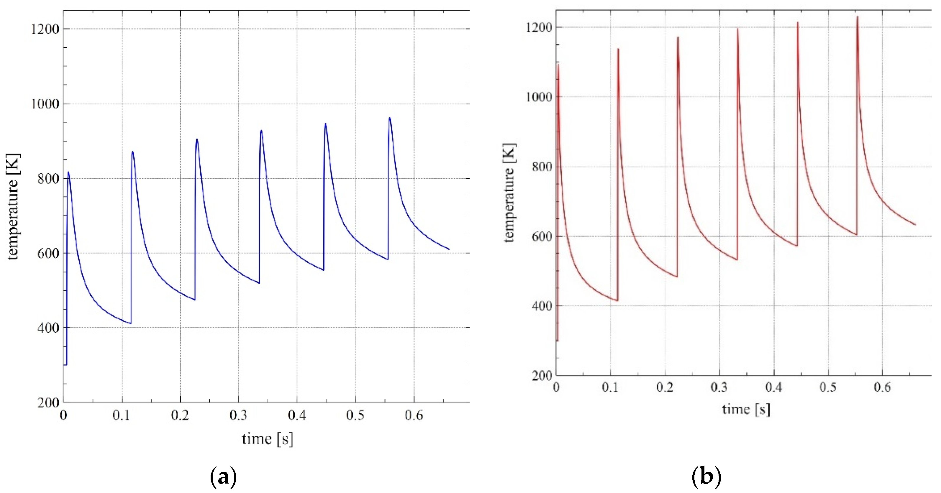
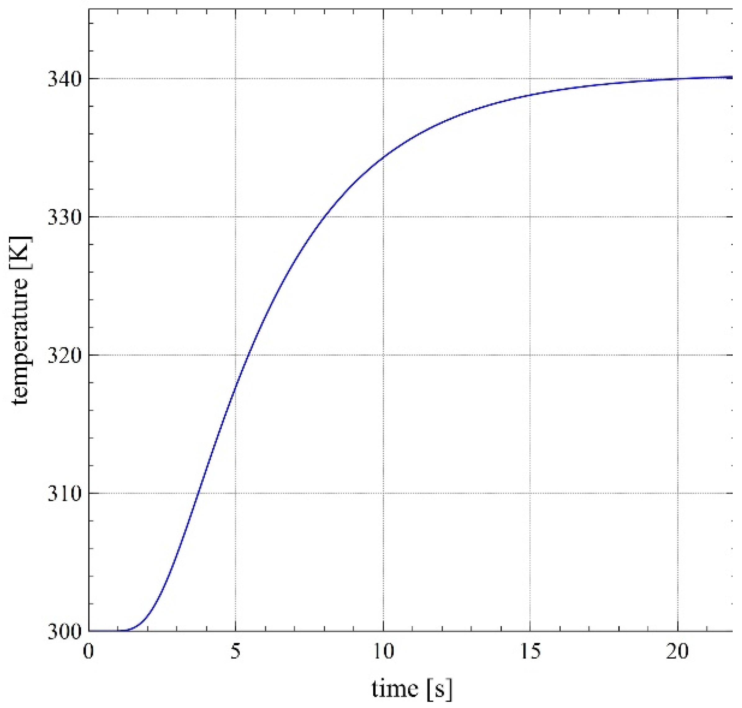
  • the theoretical estimation of barrel temperature increase (using simplified expressions defining heat flux between gases and barrel surface) provided acceptable discrepancy with the experimental data and can be recommended in similar analyses;
  • heat transfer between the propellant gases and the barrel wall is one of the most important losses and it is necessary to include this effect in simulations of interior ballistics of artillery (even middle caliber) systems;
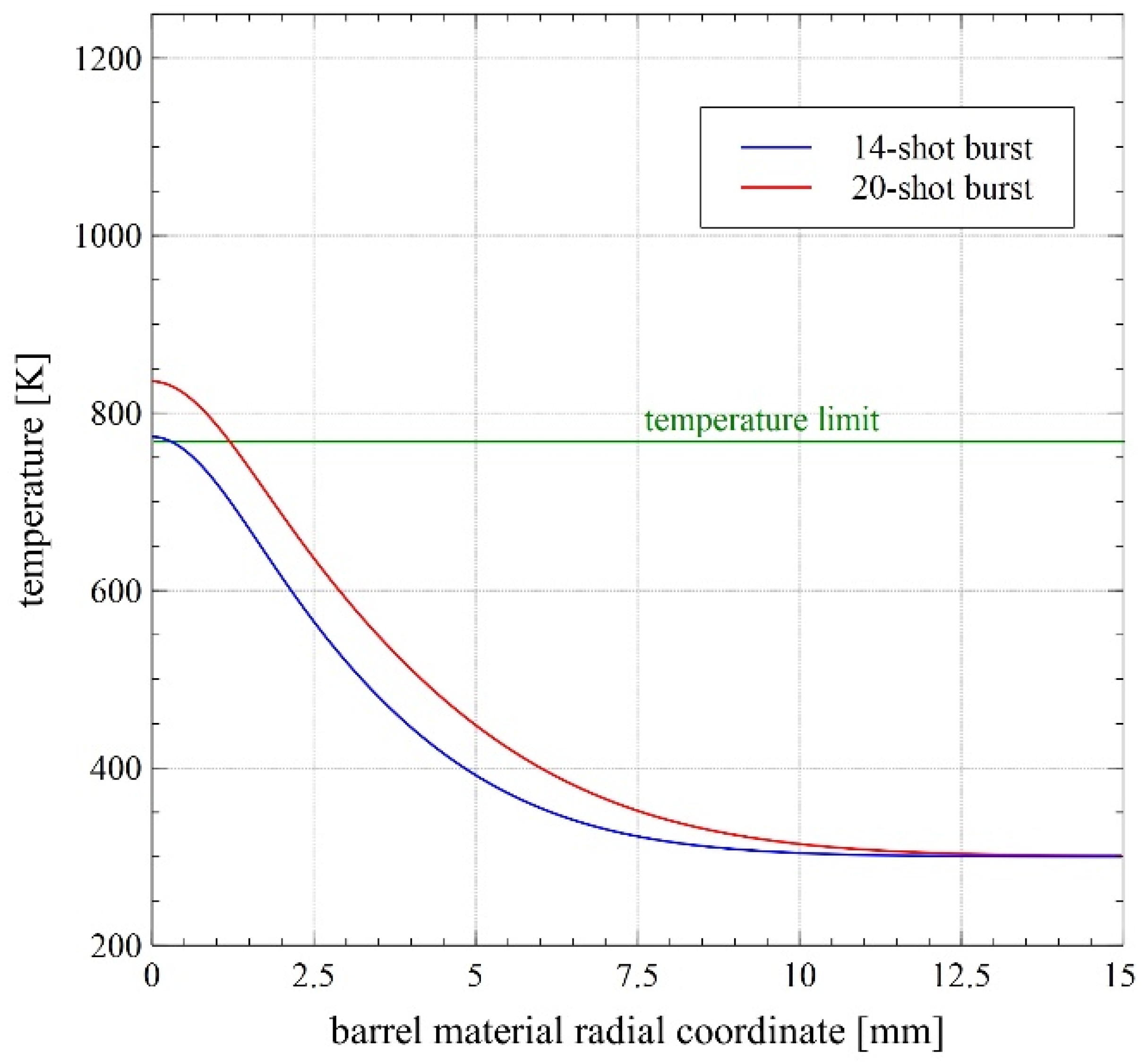
  • the conducted analyses enabled estimation of the critical burst length, equal to ca. 14 shots, which agrees with the producer’s recommendations. In our opinion, the fire regime proposed by the producer should not be changed.

Author Contributions

Conceptualization, B.F.; methodology, B.F., R.T. and A.D.; software, B.F., A.D. and R.T.; validation, B.F., A.D., J.M. and J.K.; formal analysis, B.F. and R.T.; investigation, B.F., A.D., Z.S., J.K., J.M. and R.T.; resources, Z.L.; data curation, B.F., Z.S., J.K., J.M. and R.T.; writing—original draft preparation, B.F.; writing—review and editing, A.D. and R.T.; project administration, Z.L.; funding acquisition, Z.L. All authors have read and agreed to the published version of the manuscript.

Funding

This research was funded by The National Centre for Research and Development, grant number O ROB 0046 03 001 (DOBR/0046/R/ID1/2012/03). The APC was funded by grant number O ROB 0046 03 001 (DOBR/0046/R/ID1/2012/03).

Institutional Review Board Statement

Not applicable.

Informed Consent Statement

Not applicable.

Data Availability Statement

Not applicable.

Acknowledgments

Authors would like to thank Judyta Sienkiewicz, Dawid Goździk and Damian Szupieńko for their assistance during experimental investigations.

Conflicts of Interest

The authors declare no conflict of interest.

References

  1. Płatek, P.; Damaziak, K.; Małachowski, J.; Kupidura, P.; Woźniak, R.; Zahor, M. Numerical Study of Modular 5.56 mm Standard Assault Rifle Referring to Dynamic Characteristics. Def. Sci. J. 2015, 65, 431–437. [Google Scholar] [CrossRef] [Green Version]
  2. Surma, Z.; Szmit, Ł.; Torecki, S.; Woźniak, R. Mathematical Model of Gas Operated Weapon Jump. Probl. Mechatron. Armament Aviat. Saf. Eng. 2010, 2, 51–63. [Google Scholar]
  3. Serebryakov, M. Internal Ballistics; Oborongiz: Moscow, Russia, 1949. (In Russian) [Google Scholar]
  4. STANAG 4367 LAND (Edition 2); Thermodynamic Interior Ballistic Model with Global Parameters. Military Agency of Standardization: Brussels, Belgiu, 2000.
  5. Sheu, T.W.H.; Lee, S.M. Analysis of combustion processes in a gun interior ballistics. Int. J. Comput. Fluid Dyn. 1995, 4, 57–71. [Google Scholar] [CrossRef]
  6. Shen, C.; Zhou, K.-D.; Lu, Y.; Li, J.-S. Modeling and simulation of bullet-barrel interaction process for the damaged gun barrel. Def. Technol. 2019, 15, 972–986. [Google Scholar] [CrossRef]
  7. Liu, Q.; Wang, Y.; Zhao, N.; Guo, Y. Research on influence regular of bore structure diversification on band engraving resistance. In Proceedings of the 31st International Symposium on Ballistics, Hyderabad, India, 4–8 November 2019; Saraswat, V.K., Reddy, G.S., Woodley, C., Eds.; Destech Publications Inc.: Lancaster, PA, USA, 2019. [Google Scholar]
  8. Turczyńska, A. Numerical Investigations of Shell-Barrel Interaction Phenomenon for Selected Artillery Shell. Master Degree Thesis, Military University of Technology, Warsaw, Poland, 2021. (In Polish). [Google Scholar]
  9. Li, Z.; Ge, J.; Yang, G.; Tang, J. Modeling and dynamic simulation on engraving process of rotating band into rifled barrel using three different numerical methods. J. Vibroengineering 2016, 18, 768–780. [Google Scholar]
  10. Sun, Q.; Yang, G.; Ge, J. Modeling and simulation on engraving process of projectile rotating band under different charge cases. J. Vib. Control 2017, 23, 1044–1054. [Google Scholar] [CrossRef]
  11. Fikus, B.; Płatek, P.; Surma, Z.; Sarzyński, M.; Trębiński, R. Preliminary numerical and experimental investigations of 9 mm pistol bullet and barrel interaction. In Proceedings of the 31st International Symposium on Ballistics, Hyderabad, India, 4–8 November 2019; Saraswat, V.K., Reddy, G.S., Woodley, C., Eds.; Destech Publications Inc.: Lancaster, PA, USA, 2019. [Google Scholar]
  12. Trębiński, R.; Fikus, B.; Surma, Z. Investigations of Ballistic Characteristics of N340 Propellant. Probl. Mechatronics. Armament Aviat. Saf. Eng. 2017, 8, 9–22. [Google Scholar] [CrossRef]
  13. Trębiński, R.; Leciejewski, Z.; Surma, Z.; Fikus, B. Some Considerations on the Methods of Analysis of Closed Vessel Test Data. In Proceedings of the 29th International Symposium on Ballistics, Edinburgh, UK, 9–13 May 2016; Woodley, C., Cullis, I., Eds.; Destech Publications Inc.: Lancaster, PA, USA, 2016. [Google Scholar]
  14. Fikus, B.; Surma, Z.; Trębiński, R. Preliminary Application Correctness Assessment of Physical Burning Law in Interior Ballistics Phenomena Modeling in Small-Caliber Guns. In Proceedings of the 31st International Symposium on Ballistics, Hyderabad, India, 4–8 November 2019; Saraswat, V.K., Reddy, G.S., Woodley, C., Eds.; Destech Publications Inc.: Lancaster, PA, USA, 2019. [Google Scholar]
  15. Łazowski, J.; Małachowski, J.; Kamiński, R. FE analysis of thermal loads during a shot. Bull. MUT 2008, 57, 215–228. (In Polish) [Google Scholar]
  16. Torecki, S.; Leciejewski, Z.; Surma, Z. Calculation of the barrel temperature of a 35 mm remotely controlled anti-aircraft system for the adopted firing cycle. Prob. Arm. Technol. 2011, 118. (In Polish) [Google Scholar]
  17. Surma, Z. Calculations of gun propellants parameters (in Polish). Bull. MUT 2006, 55, 171–179. [Google Scholar]
  18. Fikus, B.; Surma, Z.; Leciejewski, Z.; Trębiński, R. Influence of Relations Defining Propellant Gases—Barrel Heat Transfer on Critical Burst Length of 35 mm Anti-Aircraft Cannon. In Proceedings of the 32nd Symposium on Ballistics, Reno, NV, USA, 9–14 May 2022. [Google Scholar]
  19. Johnson, G.R.; Cook, W.H. An constitutive model and data for metals subjected to large strains, high strain rates and high temperatures. In Proceedings of the 7th International Symposium on Ballistics, The Hague, The Netherlands, 19–21 April 1983. [Google Scholar]
  20. 35 × 228 mm TP-T Projectile Datasheet. Available online: https://www.mesko.com.pl/medium-caliber-ammunition/35-x-228-mm-en/35x228-tp-t-en.html (accessed on 8 April 2021).
  21. Johnson, G.R.; Cook, W.H. Fracture characteristics of three metals subjected to various strains, strain rates, temperatures and pressures. Eng. Frac. Mech. 1985, 21, 31–48. [Google Scholar] [CrossRef]
  22. Dębski, A.; Koniorczyk, P.; Leciejewski, Z.; Preiskorn, M.; Surma, Z.; Zmywaczyk, J. Analysis of Heat Transfer in a 35 mm Barrel of an Anti-Aircraft Cannon. Probl. Mechatron. Armament Aviat. Saf. Eng. 2016, 7, 71–86. [Google Scholar] [CrossRef]
  23. Dębski, A.; Koniorczyk, P.; Leciejewski, Z.; Preiskorn, M.; Surma, Z.; Zmywaczyk, J. Heat Transfer Calculations in Barrel Cover of 35 mm Naval Armament System Gun. Probl. Mechatron. Armament Aviat. Saf. Eng. 2018, 9, 57–74. [Google Scholar]
  24. Hallquist, J.O. LS-Dyna. Theoretical Manual; Livermore Software Technology Corporation: Livermore, CA, USA, 2006. [Google Scholar]
  25. Steinberg, D.J. LLNL Report no UCRL-MA-106439—Equation of State and Strength Properties of Selected Materials; LLNL: San Francisco, CA, USA, 1996. [Google Scholar]
  26. Basic Material Properties. Available online: https://www.engineeringtoolbox.com/material-properties-t_24.html (accessed on 8 April 2021).
  27. Steel Material Properties Provided by Producer. Available online: https://files.abrams-industries.com/steel/en_eu/1.2365.pdf (accessed on 8 April 2021).
  28. Mishra, A.; Hameed, A.; Lawton, B. A Novel Scheme for Computing Gun Barrel Temperature History and Its Experimental Validation. J. Press. Vessel Technol. 2010, 132, 061202. [Google Scholar] [CrossRef]
  29. Trębiński, R.; Czyżewska, M. Estimation of the Increase in Projectile Velocity in the Intermediate Ballistics Period. Cent. Eur. J. Energetic Mater. 2015, 12, 63–76. [Google Scholar]
  30. Yong-hai, W. Analysis of the Temperature Field of a Gun Tube Based on Thermal-Solid Coupling. Res. J. Appl. Sci. 2013, 16, 4110–4117. [Google Scholar] [CrossRef]
  31. Conroy, P.J.; Bundy, M.L.; Kennedy, J.L. ARL Report no ARL-TR-770—Simulated and Experimental In-Wall Temperatures for 120-mm Ammunition; U.S. Army Research Laboratory: Aberdeen Proving Ground, MD, USA, 1995. [Google Scholar]
  32. Wang, W.; Liu, B.; Kodur, V. Effect of Temperature on Strength and Elastic Modulus of High-Strength Steel. J. Mater. Civ. Eng. 2013, 25, 174–182. [Google Scholar] [CrossRef]
Figure 1. Closed vessel HPI B180T: (a—appearance; b—cross-section (1—closed vessel with jacket, 2—pressure transducer adapter, 3—pressure relief valve).
Processes 10 00607 g001
Figure 2. Grains shapes of investigated propellant.
Processes 10 00607 g002
Figure 3. Propellant gases pressure courses obtained for loading density of 100 kg/m3 (solid line) and 200 kg/m3 (dashed line).
Processes 10 00607 g003
Figure 4. Estimated dynamic vivacity function as the function of relative burning propellant mass for loading density of 100 kg/m3 (solid line) and 200 kg/m3 (dashed line).
Processes 10 00607 g004
Figure 5. Investigated launching system (1) with Doppler radar (2).
Processes 10 00607 g005
Figure 6. Barrel region investigated using the thermographic camera.
Processes 10 00607 g006
Figure 7. Temperature distribution of the barrel external surface in the near-muzzle region.
Processes 10 00607 g007
Figure 8. Diffusive transport coefficients (a) and Prandtl number (b) of propellant gases as a function of temperature.
Processes 10 00607 g008
Figure 9. Geometry of the under-investigation system ((a)—exact geometry; (b)—simplified and meshed geometry).
Processes 10 00607 g009
Figure 10. Geometry (a) and mesh (b) for the under-investigation heat transfer problem.
Processes 10 00607 g010
Figure 11. Approximation of barrel material specific heat as a function of temperature.
Processes 10 00607 g011
Figure 12. Influence of barrel mesh size on the maximum temperature of the barrel interior surface for single shot.
Processes 10 00607 g012
Figure 13. Ballistic curves (as function of time), (a)—projectile velocity, (b)—propellant gas pressure.
Processes 10 00607 g013
Figure 14. Barrel resistance pressure as function of projectile displacement.
Processes 10 00607 g014
Figure 15. Shape of rotating band with projectile body threshold.
Processes 10 00607 g015
Figure 16. Time courses of the heat flux at the internal barrel surface ((a)—for the validation cross-section of the barrel; (b)—for the most loaded cross section).
Processes 10 00607 g016
Figure 17. Time courses of the temperature at the internal barrel surface for validation cross-section (a) and the most loaded cross-section (b).
Processes 10 00607 g017
Figure 18. Time courses of the temperature at the external barrel surface at the validation cross-section.
Processes 10 00607 g018
Figure 19. The courses of the relation of secondary works to the projectile kinetic energy as function of time.
Processes 10 00607 g019
Figure 20. Barrel material temperature radial distribution.
Processes 10 00607 g020
Figure 21. The influence of external surface heat transfer coefficient on the temperature increase of the external surface.
Processes 10 00607 g021
Table 1. Propellant grain characteristics.
ParameterValue
Grain typesingle-perforated
External diameter [mm]2
Perforation diameter [mm]0.15
Grain length [mm]2.8
Web thickness [mm]0.925
Table 2. Estimated equation of state parameters for propellant gases.
ParameterValue
(E) f = RgTg0 [kJ/kg]826
(Q) f = RgTg0 [kJ/kg]895
(E) α, [dm3/kg]1.366
(Q) α, [dm3/kg]1.153
Table 3. Results of velocity measurements.
No. of ShotsValue of Projectile Velocity [m/s]
High Speed CameraDoppler Radar *
111721175
211701170
311751180
411701178
511741171
6 11731182
711621160
average1170.91173.7
standard deviation4.347.50
max–min1322
* Measurements of Doppler radar were applied in the further model validation. The high-speed camera measurements were applied to verify the radar results in case of a disturbed radar signal.
Table 4. Results of temperature measurements.
No. of Shots in BurstValue of Temperature [deg. C]Temperature Increase [deg. C]
Before BurstAfter Burst
620.458.037.6
629.378.949.6
660.4101.441.0
average temperature increase for burst 42.7
max–min 12.0
Table 5. Approximate propellant gas composition.
CompoundMass Fraction [%]Molar Fraction [%]
CO217.49.4
CO53.044.9
H2O15.820.8
H21.214.2
N212.610.7
Table 6. Basic data of the under-investigation system [20].
ParameterValue
Barrel caliber [mm]35
Barrel length [mm]3150
Rifling twist [deg]linearly variable from 0 to 6.5
Projectile mass [g]~550
Projectile muzzle velocity obtained using ballistic barrel [m/s]1180 ± 15
Average maximum gas pressure estimated based on series of shots [MPa]≤420
Table 7. Constitutive model parameters applied during simulations.
ParameterValue
MaterialOFHC CopperSteelAluminum Alloy
Material density [kg/m3]896078502710
Young’s modulus [GPa]12421069
Poisson’s ratio0.340.300.30
Specific heat [J/(kg∙K)]383
Shear modulus [GPa]45
Yield strength [MPa] 830
Melting temperature [K]1356
Initial (room) temperature [K]300
Constant A [MPa]90
Constant B [MPa]292
Constant C [-] 0.025
Exponent n [-]0.31
Exponent m [-]1.09
Reference strain rate ε ˙ 0 [s−1]1
Table 8. Johnson–Cook failure model parameters for OFHC copper.
ParameterD1D2D3D4D5
Value [-]0.5404.889−3.0300.0141.120
Table 9. Launching system parameters applied in simulations.
ParameterValue
Initial chamber volume W0 [dm3]0.360
Projectile displacement to the muzzle lm [mm]2930
Projectile mass mp [kg]0.550
Propellant mass ω [kg]0.345
Propellant “force” f [kJ/kg]895
Co-volume coefficient α [dm3/kg]1.153
Burning law exponent n [-]0.961
Propellant gases specific heat ratio γg [-]1.2
Propellant heat of combustion qpow [MJ/kg]4.48
Propellant density δ [kg/m3]1550
Gas constant of propellant gases Rg [J/kg∙K]350
Gas constant of air Rair [J/kg∙K]287
Isochoric specific heat of propellant gases cvg [J/kg∙K]1750
Isochoric specific heat of air cv air [J/kg∙K]750
Primer pressure pign [MPa]7
Table 10. Barrel material thermophysical properties and values of temperature of processes.
ParameterValue
Material density [kg/m3]7850
Thermal conductivity [W/(m∙K)]19 + 0.014(T-293)
Hardening temperature [K]1200–1250
Tempering temperature [K]800–930
Publisher’s Note: MDPI stays neutral with regard to jurisdictional claims in published maps and institutional affiliations.

