Article

Experimental Investigation of the Growth Law of Multi-Fracture during Temporary Plugging Fracturing within a Stage of Multi-Cluster in a Horizontal Well

1
Shale Gas Exploration and Development Department, CNPC Chuanqing Drilling Engineering Company Limited, Chengdu 610051, China
2
State Key Laboratory of Petroleum Resources and Prospecting, China University of Petroleum, Beijing 102249, China
*
Author to whom correspondence should be addressed.
Processes 2022, 10(4), 637; https://doi.org/10.3390/pr10040637
Submission received: 24 January 2022 / Revised: 1 March 2022 / Accepted: 15 March 2022 / Published: 24 March 2022

Abstract

:
Temporary plugging fracturing in a horizontal well with multi-stages and multi-clusters is usually used to improve stimulation efficiency and increase the gas production from shale gas reservoirs. However, the fracture propagation geometry and the mechanism of temporary plugging are still unclear, which restricts the further optimization of temporary plugging fracturing scheme. In this study, taking the Longmaxi shale as the research object and considering the intrafracture and intrastage temporary plugging, the true tri-axial hydraulic fracturing system was used to put forward an experimental method for simulating the temporary plugging fracturing in a horizontal well with multi-stages and multi-clusters. Afterward, the effects of the size combination and concentration of temporary plugging agents and the cluster number in a stage on the fracture geometry created in the secondary fracturing were investigated in detail. The results show that an optimal fracture propagation geometry tends to be obtained by using the combinations of 100 to 20/70 mesh, and 20/70 to 10~18 mesh temporary plugging agents for the intrafracture and intrastage temporary plugging, respectively. Increasing the proportion of the temporary plugging agent of a larger particle size can improve the effectiveness of intrafracture and intrastage temporary plugging fracturing, and tends to open new fractures. With the increase in temporary plugging agent concentration and the cluster number within a stage, both the number of diverting fractures formed and the overall complexity of fractures tend to increase. After fracturing, the rock specimen with a high peak in the temporary plugging pressure curve has more transverse fractures, indicating a desirable diversion effect. By contrast, the fractured rock specimen with a low peak pressure has no transverse fracture, generally with fewer fractures and poor diversion effect.

1. Introduction

Unconventional reservoirs such as shale have extremely low permeability. The function of hydraulic fractures will be undermined (e.g., fracture closure) after a long-term production, which will lead to a decline in oil and gas production [1,2]. Correspondingly, it is difficult to achieve the economic and efficient development of shale oil and gas resources. Therefore, the secondary reservoir stimulation is required to improve the fracture complexity and increase the stimulation volume, accordingly increasing the production in a single well [3,4]. The temporary plugging fracturing is an important technique to improve the fracture network stimulation efficiency of the re-fracturing in shale reservoirs [5,6]. This method can provide a favorable plugging performance, and the treatment workflow is relatively simple, with a low operation risk [7,8,9]. However, the influence mechanism of temporary plugging fracturing on the law of hydraulic fracture propagation in shale is not clear [10,11].
To date, several studies related to the temporary plugging fracturing technique have been carried out through experimental and numerical methods [12,13,14,15,16,17,18,19,20]. Jin et al. [12,13,14,15] studied the influence of the combination and concentration of temporary plugging agents on fracture propagation in the fracturing process of open hole vertical wells through experimental simulation, and came to the conclusion that a high concentration of temporary plugging agent, and multi-particle particle or fiber + particle temporary plugging agent can achieve better plugging effect. Xiao et al. [16] initially initiated the temporary plugging fracturing simulation technology suitable for shale gas horizontal wells. Based on the stress changes caused by the initial hydraulic fracturing of shale gas, they studied the temporary plugging fracturing process and optimized the operation parameters (such as the size combination and dosage of temporary plugging agent). Zou et al. [17] and Chen et al. [18] further conducted numerical simulations of the temporary plugging and fracturing process of horizontal wells on a field scale to explore the effects of dominant factors on the fracture propagation geometry in the intrafracture and intrastage temporary plugging schemes, respectively, and demonstrated the availability and applicability of temporary plugging treatments. However, most of the previous studies focused on laboratory open-hole vertical well fracturing [21,22], and few experiments considered the temporary plugging fracturing in a horizontal well with multi-clusters and multi-stages. In addition, there lacks an adequate experimental investigation of the fracture propagation of horizontal temporary plugging fracturing in natural shale, and the effect of cluster number in a stage is not clear. Those insufficient studies mentioned above correspondingly lead to the ambiguous knowledge of the fracture propagation geometry and dominant controlling factors, constraining the optimization design of engineering parameters in the temporary plugging fracturing of shale.
To solve the above problems, a new method for a temporary plugging test of multi-stage and multi-cluster horizontal wells considering temporary plugging in fractures and stages was proposed, and a simulation experiment was carried out. The experimental samples were taken from shale outcrop of Longmaxi Formation. Moreover, the effects of size combination and concentration of temporary plugging agents and cluster number within a stage on the fracture propagation geometry were analyzed in detail. The investigation conclusions are aimed to provide guidance for the optimization of engineering parameters of horizontal temporary plugging fracturing in shale.

2. Experimental Methods

Through the XRD analysis and mechanical property experiment of outcrop, the petro-physical properties of Longmaxi Shale were studied to support fracture propagation experiments. After that, a set of true tri-axial fracturing simulation system was applied for fracturing physical simulation experiment with shale samples. Then, the influence of particle size combination and concentration of temporary plugging agents on fracture propagation of Longmaxi Formation shale were analyzed.

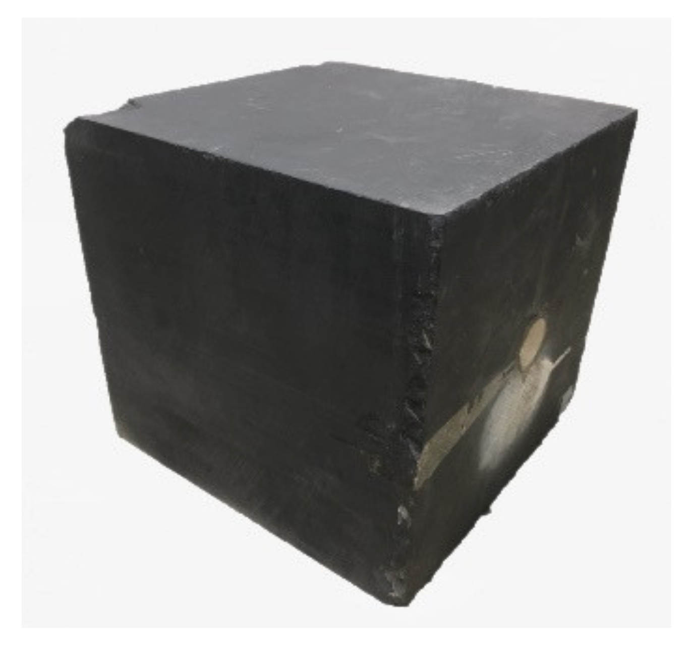
2.1. Specimen Preparation

The rock specimens used in this experiment were collected from the shale crop of the Longmaxi formation. The X-ray diffraction (XRD) analysis was carried out on the shale outcrop. Results indicate that, on average, the specimen contains 51.7% siliceous minerals, 9.5% carbonate minerals, 33.2% clay minerals, and 5.6% pyrite. In addition, triaxial compression test and Brazilian split tension test using an integrated mechanical test instrument were conducted to evaluate the anisotropy of mechanical parameters of rock specimens. Test load direction can be divided into vertical bedding planes and parallel bedding planes direction. Test results are shown in Table 1.
The shale outcrop was cut into a cube of 30 cm × 30 cm × 30 cm by using a large-scale stone cutter (see Figure 1). Afterward, the shale surface was sealed by coating a resin glue layer, which can mitigate the cracking of a large number of bedding planes caused by the long-term exposure to the air.
To simulate the process of putting down the casing and cementing after drilling in the field, a special coring bit with the outer diameter of 30 mm and height of 27 cm was used to drill a 25 cm deep borehole along the bedding planes at the surface center of the cubic block. Then, a polyvinyl chloride (PVC) pipe, with the outer diameter of 25 mm, inner diameter of 22 mm, and length of 25 cm was put into the wellbore. To model the cementing in the field, the epoxy resin was injected into the annulus between the PVC casing and rock specimen to bond them together [23]. It is noted that the bottom of the PVC casing was sealed with gypsum to prevent the resin from leaking into the PVC casing. Meanwhile, the surface of the PVC casing was grooved to increase the roughness to enhance the bonding strength between the PVC casing and rock specimen.
To simulate the tight-spacing fracturing in a horizontal well, a notch cutting apparatus was applied to cut circle notches inside the wellbore to model multiple perforation clusters within the stage [23,24]. According to the combination schemes of different stage spacing, cluster spacing, and cluster number in a stage, the cutting blade was located at the corresponding depth to sequentially cut the PVC casing, epoxy resin layer at the annular, and the shale block. Each notch was cut 2~3 mm deep into the rock specimen to simulate the casing perforation completion mode.

2.2. Experimental Instruments and Procedures

The true tri-axial fracturing simulation system was adopted in this experiment [25]. The frequency conversion loading technology was applied during the imposing the tri-axial stresses. The loading was increased at a fast rate to a preset value through the hydraulic station, and then the loading was accurately adjusted to the exact value by using the control panel, such that the real in situ stresses may be achieved. The X-axial maximum stress can reach 15 MPa, and the Y-axial and Z-axial maximum stress can both reach 30 MPa.
Four kinds of temporary plugging agents with particle sizes of 200/300 mesh, 100 mesh, 20/70 mesh, and 1~2 mm were selected in this experiment. Before the temporary plugging fracturing, the initial conventional fracturing was performed with an injection rate of 200 mL/min and a viscosity of 2–5 MPa·s. After that, the fracturing fluid system used in the primary fracturing was replaced with the fracturing fluid containing the temporary plugging agents, such that the temporary plugging fracturing can be carried out with the replaced frac-fluid. The experimental flow chart is shown in Figure 2 and the specific experimental procedures are as follows:
  • Connect the pipelines and put the rock specimen into the pressurization chamber of the experimental system by making the wellbore axis consistent with the X-axis.
  • Push the hydraulic piston into the chamber along the X-axis. Following that, apply the vertical stress σv along the Z-axis, and increase the horizontal maximum principal stress σH and horizontal minimum principal stress σh along the Y- and X-axes to the preset value. Meanwhile, the tri-axial stresses were maintained stable.
  • Connect the injection pipe inside the simulated wellbore to the six-way valve, and connect the intermediate container containing the fracturing fluid to the six-way valve.
  • Open the valve corresponding to the pipeline of the fracturing stage with no temporary plugging agents added, and also open the valve corresponding to the intermediate container, meanwhile keeping the other valves closed. Turn on the fluid injection system and pump the fracturing fluid into the wellbore at a constant rate to commence the primary fracturing experiment. During the primary fracturing, the pressure transducer is used to record the wellhead pressure change until the designed fluid volume is injected. Stop the pump when the pressure stabilizes and close the valve of the corresponding injection pipeline.
  • Afterward, clean the intermediate container and pour into the prepared fracturing fluid containing the temporary plugging agents. Then, the intrafracture and intrastage temporary plugging fracturing experiments were carried out. Repeat the operations in step 4 to complete the temporary plugging fracturing experiments mentioned above.
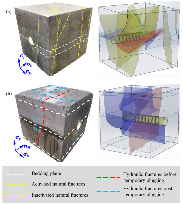
  • After the experiment, take out the rock specimen. The hydraulic fractures created from the corresponding stage are identified according to colors of the dye agents on the fracture surfaces, and the fracture propagation trajectories formed during the temporary plugging fracturing were analyzed. The fracture geometry of the sample by CT scanning technology were obtained, and we used SolidWorks to make 3D reconstruction images.
Figure 2. (a) Schematic diagram of horizontal well temporary plugging fracturing experimental device; (b) Schematic diagram of sample temporary plugging crack [26].
Processes 10 00637 g002

2.3. Experimental Parameters

According to the actual in situ stress conditions of Longmaxi shale reservoirs [27,28,29], the stress mechanism of the strike-slip faults was adopted in this study, i.e., σv = 20 MPa, σH = 25 MPa, and σh = 10 MPa. The pumping injection rate was set to 200 mL/min and the viscosity of fracturing fluid was 2–5 MPa·s. A total of nine experiments were designed to explore the effects of size combination and concentration of temporary plugging agents and cluster number within a stage on the fracture propagation geometry. In each scheme, a combination of two temporary plugging agents with different particle sizes and different masses are used, 2 L fracturing fluid was used per test. The specific experimental scheme is indicated in Table 2.

3. Characterization of Fracture Propagation Geometry

3.1. The Influence of Particle Size Combination

Temporary plugging agents composed of different particle size are often sent to plug the fracture near the well and promote the fracture diversion in the fracturing process, since the temporary plugging efficiency of multi-particle size combined temporary plugging agents are better than that of single particle size temporary plugging agents [30,31,32,33]. Four groups of rock specimens were designed for comparative experiments in order to study the influence of different particle size combinations of temporary plugging agents on the fracture propagation geometry in temporary plugging fracturing, respectively, 1#, 2#, 3#, and 4#.
In the first conventional fracturing of specimen 1#, two transverse fractures were formed to open a bedding plane centered on the wellbore. The two transverse fractures propagate vertically from the bottom surface of the rock specimen to the bedding plane and cut off, as shown by the red dotted line in the left figure of Figure 3a. This indicates that the transverse fracture is cut off after encountering weak bedding plane in the process of propagation. Due to the influence of stress difference and net pressure in the fracture, the hydraulic fracture cannot pass through the bedding fracture and continue to extend upward along the direction of maximum principal stress. By observing fracture geometry after temporary plugging fracturing, two transverse fractures and one longitudinal fracture were added in the specimen compared with those before the temporary plugging, as shown by the blue dotted line in the left figure of Figure 3a. One of the new transverse fractures is basically parallel to the old one and also ends at the bedding plane. The direction of the other transverse fracture is offset after the intersection with the old fracture, but there is no cut-off. It indicates that new transverse fractures are formed in new perforation clusters. In addition, because of the role of temporary plugging agents in the old fracture, the new fracture did not propagate along the old fracture.
In the first conventional fracturing of specimen 2#, an oblique bedding plane was formed below the wellbore, as shown by the red dotted line at the left of Figure 3b. By observing fracture geometry after temporary plugging fracturing, two bedding fractures and one longitudinal fracture were added in the specimen compared with those before the temporary plugging, and the two bedding planes were basically parallel to the oblique bedding plane. The longitudinal crack propagated near the edge of the specimen, as shown by the blue dotted line in the left figure of Figure 3b. In the first conventional fracturing of specimen 3#, three bedding fractures and two transverse fractures were formed after fracturing, as shown by the red dotted line on the left of Figure 3c. By observing the fracture geometry after temporary plugging fracturing, two transverse fractures and two longitudinal fractures were added in the specimen compared with those before the temporary plugging, and the transverse fractures and those formed by conventional fracturing formed multiple bedding fractures on S2 plane, as shown by the blue dotted line in the left figure of Figure 3c. Specimen 4# was fractured at 8.6 MPa during the first conventional fracturing, and the fracture slightly open the bedding plane, as shown by the red dotted line on the left of Figure 3d. By observing fracture geometry after temporary plugging fracturing, a transverse fracture and a longitudinal fracture were added in the specimen compared with those before the temporary plugging, as shown by the blue dotted line in the left figure of Figure 3d.

3.2. The Influence of Temporary Plugging Agent Concentration

In order to reveal the influence of temporary plugging agent concentration on fracture propagation, three groups of experimental rock specimens were designed under the condition of the same cluster number (seven clusters). Rock specimens were numbered as 3#, 6#, and 7#, and the concentration of temporary plugging agents was shown in Table 2. Fracture geometry of specimen 3# after temporary plugging fracturing is shown in Figure 3c. A transverse fracture was formed after conventional fracturing of specimen 6#, which slightly open bedding plans of the rock specimen. The overall fracture geometry of specimen 6# after temporary plugging fracturing is shown in the left figure of Figure 4a, which contains two new bedding fractures and one new transverse fracture. In addition, the new fracture intersected with five natural fractures. The bedding fractures initiated through two vertical natural fractures, and the transverse fractures initiated between two narrow bedding fractures. Three bedding fractures were formed after conventional fracturing of specimen 7#. The overall fracture geometry of specimen 7# after temporary plugging fracturing is shown in the left figure of Figure 4b, which contains three bedding fractures, two transverse fracture and two longitudinal fractures. The longitudinal and transverse fractures intersected at the top of the rock sample in a “#”-shaped manner, and a transverse fracture intersected three longitudinal fractures in an “ᵻ”-shape on the lateral side of the rock specimen.

3.3. The Influence of the Cluster Number in a Stage

Four groups of rock specimens with different cluster numbers were designed to analyze the influence of the cluster number on fracture propagation, and the rock specimen numbers were 5#, 8#, 3#, and 9#, respectively. The four groups of rock samples had the same size combination of temporary plugging agents, and the concentration of the intrafracture and intrastage temporary plugging agents are the same, which are 40 g/L and 30 g/L, respectively. Figure 3c shows the fracture geometry after temporary plugging fracturing of specimen 3#, which have seven perforation clusters. During the conventional fracturing of specimen 5# with three perforation clusters, the fracture propagated along the bedding plane, creating a bedding fracture near the wellhead cluster. The overall fracture geometry of specimen 5# after temporary plugging fracturing is shown in the left figure of Figure 5a, which contains two bedding fractures and three transverse fractures. A bedding plane is fully open above the wellbore, and the three transverse fractures are evenly distributed in the rock specimen longitudinally. During the conventional fracturing of specimen 8# with five perforation clusters, the fracture slightly propagated along the bedding plane. The overall fracture geometry of specimen 8# after temporary plugging fracturing is shown in the left figure of Figure 5b, which contains three bedding fractures, two transverse fracture, and two natural fractures. Two bedding fractures were located at the upper part of the sample and one was located at the lower part of the sample, and the bedding fractures connected some natural fractures and then diverged. During the conventional fracturing of specimen 9# with nine perforation clusters, the fracture slightly propagated along the bedding plane. The overall fracture geometry of specimen 9# after temporary plugging fracturing is shown in the left figure of Figure 5c, which contains two bedding fractures, one transverse fracture and one natural fractures. One of the oblique bedding fractures ran through the sample, while the other propagates in parallel and ends at the wellbore. The direction of natural fracture was roughly parallel to the two inclined bedding fractures. Temporary plugging fracturing caused new fractures to propagate in the natural fractures and then to stop at the inclined bedding.

4. The Evaluation on Effectiveness of Temporary Plugging

4.1. The Influence of Particle Size Combination

The influence of different particle size combinations of temporary plugging agents on the effectiveness of temporary plugging was evaluated based on the experimental pressure curve, as shown in Figure 6. In the intrafracture temporary plugging fracturing of specimen 1#, 60 g of 200–300 mesh + 20 g of 20–70 mesh (40 g/L) temporary plugging agent was pumped into the well. With the injection of the temporary plugging agent, the pressure rose with fluctuation and started decreasing after the pressure reached the maximum pressure of 11.3 MPa at 290 s, which was 4.0 MPa higher than the breakdown pressure of conventional fracturing. The temporary plugging agent accumulated continuously during this process, sealing the old fractures, thus increasing the pressure gradually. Then the pressure dropped, which indicated the formation of new fractures, and the pressure further dropped after the new fractures reach the boundary of the rock specimen. During intrastage temporary plugging fracturing, 40 g of 20–70 mesh + 20 g of 10–18 mesh (30 g/L) temporary plugging agent was pumped into the well. In the process of injection, the pressure rose rapidly to 11 MPa, then rose slowly with fluctuation, and finally reached 14 MPa, when the new fractures initiated. The breakdown pressure of intrastage temporary plugging fracturing was 3 MPa higher than that of the intrafracture temporary plugging fracturing.
In the intrafracture temporary plugging fracturing of specimen 2#, 60 g of 200–300 mesh + 20 g of 20–70 mesh (40 g/L) temporary plugging agent was injected. The pressure rose with a slight fluctuation as the injection continued. The pressure dropped at 650 s when the pressure reached the maximum pressure of 8.5 MPa, which was 9.0 MPa lower than the breakdown pressure of conventional fracturing. This pressure decline can be interpreted as invalid temporary plugging of old fractures in this process. During the intrastage temporary plugging fracturing, 40 g of 200–300 mesh + 20 g of 100 mesh (30 g/L) temporary plugging agent was added. During the injection process, the pressure rose rapidly to 9.3 MPa, and then maintained at this level. The temporary plugging pressure increased by 1 MPa.
In the intrafracture temporary plugging fracturing of specimen 3#, 20 g of 100 mesh + 60 g of 20–70 mesh (40 g/L) temporary plugging agent was injected. The pressure fluctuated showing a rising trend with the injection of the temporary plugging agent, and continued to fluctuate in a large range after the pressure reached the maximum pressure of 18.3 MPa at 190 s. The pressure was 10.0 MPa higher than the breakdown pressure of conventional fracturing. Injection of the temporary plugging agent led to formation of new fractures in this process. During intrastage temporary plugging fracturing, 40 g of 20–70 mesh + 20 g of 10–18 mesh (30 g/L) temporary plugging agent was added. In the process of injection, the pressure rapidly rose to 16.1 MPa and continued to fluctuate greatly. Compared with the breakdown pressure of intrafracture temporary plugging fracturing, the breakdown pressure of intrastage temporary plugging fracturing was 2 MPa lower.
In the temporary plugging fracturing of specimen 4#, 60 g of 100 mesh + 20 g of 20–70 mesh (40 g/L) temporary plugging agent was pumped. With the injection of the temporary plugging agent, the pressure increased but not significantly, and remained at the same level after reaching the maximum pressure of 4.5 MPa at 300 s, which was 4.0 MPa lower than the breakdown pressure of conventional fracturing. During the intrastage temporary plugging fracturing, 40 g of 100 mesh + 20 g of 20–70 mesh (30 g/L) temporary plugging agent was added. During the injection process, the pressure rose rapidly to 7 MPa, and then remained at the same level, which increased by 3 MPa compared with the breakdown pressure of intrafracture temporary plugging.
Under different particle size combinations, the peak pressure of intrafracture temporary plugging fracturing and that of the intrastage temporary plugging fracturing were compared, as shown in Figure 7. When the 60 g of 100 mesh + 20 g of 20–70 mesh particle size combination was used for the intrafracture temporary plugging fracturing, no obvious breakdown pressure was observed, and the peak propagation pressure was 4.5 MPa; similarly, the intrastage temporary plugging fracturing using 40 g of 100 mesh + 20 g of 20–70 mesh particle size combination also showed no obvious breakdown pressure, and the peak extension pressure was 7 MPa. In addition, the peak pressures of both intrafracture temporary plugging and intrastage temporary plugging were lower than that of the conventional fracturing, indicating that the plugging effect of those particle size combinations of the temporary plugging agent was poor, and the temporary plugging agent tended to flow along the old fracture during this process. During this process, only one transverse fracture and one longitudinal fracture were formed by the temporary plugging fracturing. However, in the intrafracture temporary plugging, the peak pressure can reach 18.3 MPa with the particle size combination of 20 g of 100 mesh and the 60 g of 20–70 mesh, which is about 4.1 times as great as the peak pressure of the particle size combination of 60 g of 100 mesh + 20 g of 20–70 mesh. In the intrastage temporary plugging fracturing, the peak pressure can reach 16.1 MPa when the particle size combination is 20–70 mesh and 10–18 mesh, which is about 2.3 times as great as that of the particle size combination of 100 mesh + 20–70 mesh. At the same time, the peak pressure of temporary plugging fracturing under the combination of 20 g of 100 mesh and 60 g of 20–70 mesh is higher than that of conventional fracturing. In this case, two new fractures, a transverse one and a longitudinal one, were formed after the temporary fracturing. The newly formed transverse fracture and old transverse fracture obtained from conventional fracturing communicated with multiple bedding planes.
From the above analysis, it can be concluded that when the concentration of the temporary plugging agent is the same and the number of clusters in a single stage is the same, increasing the proportion of the temporary plugging agent of a larger particle size can improve the effectiveness of intrafracture and intrastage temporary plugging fracturing, and tends to open new fractures, and increases the complexity of fractures.

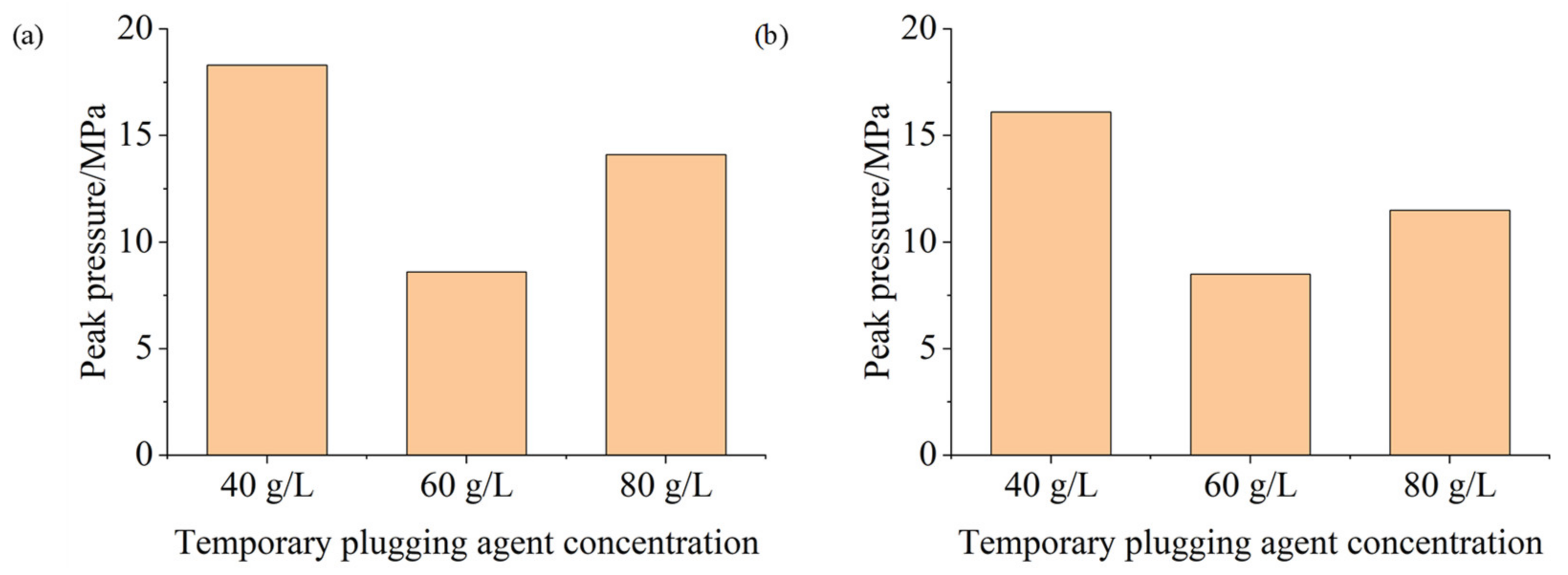
4.2. The Influence of Temporary Plugging Agent Concentration

The influence of the concentrations of the temporary plugging agent on the effectiveness of temporary plugging was evaluated based on the pressure curve, as is shown in Figure 8. In the intrafracture temporary plugging fracturing of specimen 6#, 60 g of 100 mesh + 60 g of 20–70 mesh (60 g/L) temporary plugging agent was added. With the injection of the temporary plugging agent, the pressure fluctuated and showed a rising trend. The peak pressure was 8.6 MPa, which was 4.3 MPa higher than the breakdown pressure of conventional fracturing. During the intrastage temporary plugging fracturing, 40 g of 20–70 mesh + 20 g of 10–18 mesh (30 g/L) temporary plugging agent was pumped. During the injection, the pressure rose sharply in the beginning, then fluctuated slowly, and finally rose to 8.5 MPa. In the intrafracture temporary plugging fracturing of specimen 7#, 100 g of 100 mesh + 60 g of 20–70 mesh (80 g/L) temporary plugging agent was injected, the pressure constantly fluctuated, and finally rose to 14.1 MPa. While in the intrastage temporary plugging fracturing, 80 g of 20–70 Mesh +60 g of 10–18 mesh (70 g/L) temporary plugging agent was added, the pressure rose rapidly for a period of time and then fluctuated continuously, and finally rose to 11.5 MPa.
The peak pressure of intrafracture and intrastage temporary plugging fracturing under different concentrations of temporary plugging agent was compared, as shown in Figure 9. When the concentration of the temporary plugging agent was 40 g/L, the peak pressure of intrafracture temporary plugging fracturing was 18.3 MPa, and the peak pressure of intrastage temporary plugging was 16.1 MPa, both of which are greater than the breakdown pressure of conventional fracturing, indicating that the temporary plugging agent has a good plugging effect under this concentration. Two transverse fractures and two longitudinal fractures were formed after the temporary plugging and fracturing. When the concentration of the temporary plugging agent was 60 g/L, the peak pressure of intrafracture temporary plugging was 8.6 MPa, and the peak pressure of intrastage temporary plugging fracturing was 8.5 MPa, both of which were twice as much as the breakdown pressure of the conventional fracturing, indicating that the temporary plugging agent concentration has a good plugging effect and can increase the stimulation volume. After the temporary plugging and fracturing, one bedding plane and one transverse fracture were formed, which communicated with five natural fractures. When the concentration of the temporary plugging agent was 80 g/L, the peak pressure of temporary plugging in the fracture was 14.1 MPa, which was greater than the breakdown pressure of the conventional fracturing, the peak pressure of the intrastage temporary plugging was 11.5 MPa, which was close to the breakdown pressure of the conventional fracturing, indicating that the plugging performance was better under this concentration of the temporary plugging agent and new fractures can be opened. Two transverse fractures and two longitudinal fractures were formed after the temporary plugging and fracturing. The transverse fracture 1 and 2 intersected with the longitudinal fracture 3 and 4 to form a “#”-shaped network. Fracture 1 crossed the three bedding planes to form a “ᵻ”-shape geometry, and the longitudinal fracture 3 penetrated through the bedding plane 2 to form a semicircle and stop at the bedding plane 2. The plugging effectiveness of the temporary plugging agents under these three concentrations was similar, but the fracture geometry after temporary plugging fracturing was different. Although new fractures were generated when the concentration was 40 g/L, they were not connected to the old ones, and the fractures were complex. The increase in fracture complexity was not obvious. When the concentration was 60 g/L, not only were new bedding planes and transverse fractures formed, but also five natural fractures were activated. When the concentration was 80 g/L, not only were two new transverse fractures and two longitudinal fractures formed, but these new seams were also intersected with each other, further increasing the complexity of the fracture system.
From the above analysis, it can be concluded that when the temporary plugging agent of the same particle size combination was used, increasing the concentration of the temporary plugging agent can improve the effectiveness of the intrafracture and intrastage temporary plugging, resulting in a more fracture complexity.

4.3. The Influence of the Cluster Number in a Stage

The influence of the number of clusters in a single stage on the effectiveness of temporary plugging was evaluated based on the pressure curve, and the pressure curve is shown in Figure 10. In the intrafracture temporary plugging fracturing 5# specimen, 60 g of 100 mesh + 20 g of 20–70 mesh (40 g/L) temporary plugging agent was added, the pressure rose rapidly before 200 s, and it rose to 18.7 MPa. Then, 40 g 100 mesh + 20 g 10–18 mesh (30 g/L) temporary plugging agent was added during the intrastage temporary plugging fracturing. The pressure continued to fluctuate, rising to 23.9 MPa, which was 15.7 MPa higher than the breakdown pressure of conventional fracturing. Intrafracture temporary plugging fracturing of specimen 8# was performed by adding 80 g of 100 mesh + 40 g of 20–70 mesh (40 g/L) temporary plugging agent. The pressure fluctuated and rose to 11.2 MPa with the injection of the temporary plugging agent. The intrastage temporary plugging pressure fracturing applied 60 g of 20–70 mesh + 40 g of 10–18 mesh (50 g/L) temporary plugging agent. The pressure was increased to 27.9 MPa, which was 14.8 MPa higher than the breakdown pressure of conventional fracturing. The intrafracture temporary plugging fracturing of specimen 9# was carried out by adding temporary plugging agent of 60 g of 100 mesh + 20 g of 20–70 mesh (40 g/L), the pressure rose rapidly for a period of time and then fluctuated continuously, rose to 9.2 MPa, and then began to drop. During intrastage temporary plugging fracturing, the temporary plugging agent of 40 g of 20–70 mesh + 20 g of 1–2 mm (30 g/L) was pumped, and the pressure was increased to 9.1 MPa.
The peak pressure of the intrafracture temporary plugging and intrastage temporary plugging under different number of clusters in a single stage was compared, as shown in Figure 11. In the specimen with three clusters in a single stage, the peak pressure of the intrafracture temporary plugging fracturing was 18.7 MPa. The peak pressure of the intrastage temporary plugging was 23.9 MPa, which was more than 10 MPa higher than the breakdown pressure of conventional fracturing. Five fractures were formed after the temporary plugging fracturing, including two bedding planes and three transverse fractures. When fracturing in the specimen with five clusters in a single stage, the peak pressure of the intrafracture temporary plugging fracturing was 11.2 MPa and the peak pressure of the intrastage temporary plugging fracturing was 27.9 MPa. Seven fractures were formed after the temporary plugging and fracturing, which included three bedding planes, two transverse fractures, and two natural fractures. Two of the three beddings planes were opened in the upper part of the rock specimen, and the other one was an oblique bedding planes initiated from the bottom part, which communicated with the natural fractures. When there were seven clusters in a single stage, the peak pressure of the intrafracture temporary plugging fracturing was 18.3 MPa; the peak pressure of the intrastage temporary plugging was 16.1 MPa. Nine fractures were formed after the temporary plugging fracturing, namely, three bedding planes and four transverse fractures, and two longitudinal fractures. The bedding planes were extended along the two transverse fracture 1 and 2 to form a step-shaped propagation, and the transverse fracture 1 penetrated through the three bedding planes vertically, and the fracture 2 penetrated through the two bedding planes in the lower part of the specimen. When the specimen with nine clusters in a single stage was temporary plugging fractured, the peak pressure of the intrafracture temporary plugging fracturing was 9.2 MPa; the peak pressure of the intrastage temporary plugging fracturing was 9.1 MPa. After the temporary plugging fracturing, four fractures were formed including two bedding planes, a transverse fracture, and a natural fracture. One of the oblique beddings penetrated the specimen, and the other oblique bedding plane extended parallel the first bedding plane and ended at the wellbore. The direction of the natural fracture was roughly parallel to the two oblique beddings. The natural fracture was turned to form new fractures. The natural fractures stopped at the oblique bedding plane.
From the above analysis, it can be concluded that under the same combination of temporary plugging agent concentration and particle size, the peak pressure of intrafracture and intrastage temporary plugging fracturing of the specimen with fewer clusters were higher than that of the specimen with more clusters. The peak pressure was as high as 18.7 MPa under the conditions of three clusters, and the peak pressures of five clusters and seven clusters are all greater than 10 MPa. However, the peak pressures of specimen with nine clusters were less than 10 MPa. On the whole, the more clusters in a single stage, the greater the number of diversion fractures and the higher the complexity of the fractures.

5. Conclusions

Taking the Longmaxi shale as the research object, the true tri-axial temporary plugging fracturing experiments were conducted to study the effects of the size combination and concentration of temporary plugging agents and the cluster number in a stage on the fracture geometry. The main conclusions can be obtained as follows:
  • Increasing the proportion of the temporary plugging agent of a larger particle size can improve the effectiveness of intrafracture and intrastage temporary plugging fracturing, and tends to open new fractures. More fractures can be produced by using the combinations of 100 mesh to 20/70 mesh and 20/70 mesh to 10~18 mesh temporary plugging agents for the intrafracture and intrastage temporary plugging, respectively.
  • Increasing the concentration of the temporary plugging agent and increasing clusters in a single stage can improve the effectiveness of the intrafracture and intrastage temporary plugging, resulting in a more fracture complexity.
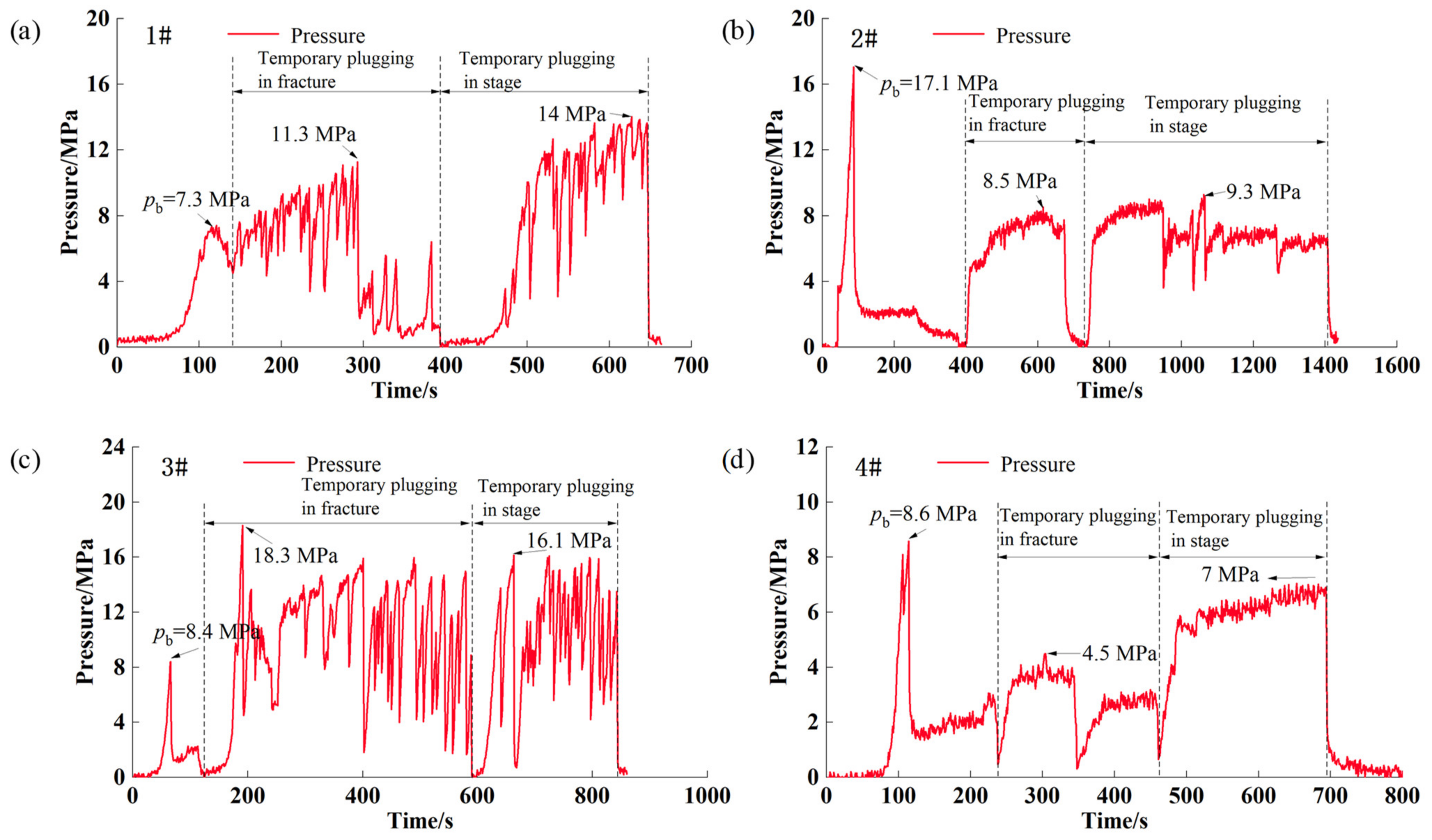
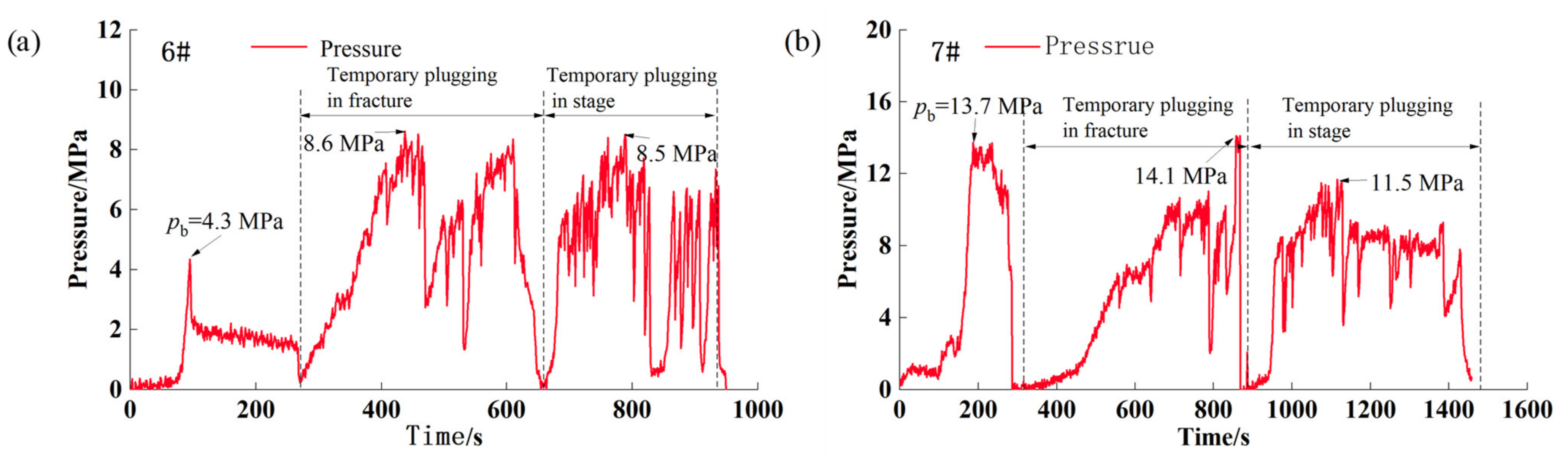
  • After fracturing, the rock specimens with a high peak in the temporary plugging pressure curve have more transverse fractures, indicating a desirable diversion effect. By contrast, the fractured rock specimen with a low peak pressure has no transverse fracture, generally with fewer fractures and poor diversion effect.

Author Contributions

Conceptualization, Y.L.; methodology, Y.Z.; investigation, Q.Z.; writing—original draft preparation, Y.Z.; writing—review and editing, Y.Z. All authors have read and agreed to the published version of the manuscript.

Funding

This research received no external funding.

Informed Consent Statement

Not applicable.

Data Availability Statement

The data presented in this study are available on request from the corresponding author. The data are not publicly available due to oilfield data confidentiality.

Conflicts of Interest

The authors declare no conflict of interest.

References

  1. Liu, X.J.; Liang, L.X.; Cheng, Z.; Liu, Z.J.; Ye, Z.B.; Li, Y. Influence of critical fluid pressure for fracture closure on oil and gas field development. Nat. Gas Ind. 2005, 25, 2. [Google Scholar]
  2. Taleghani, A.D.; Cai, Y.; Pouya, A. Fracture closure modes during flowback from hydraulic fractures. Int. J. Numer. Anal. Methods Geomech. 2020, 44, 1695–1704. [Google Scholar]
  3. Wang, T.; Chen, M.; Li, L.C.; Wu, J.; Lu, J.K.; Chang, Z.; Fan, M.; Geng, Z. Experimental Study on Improving Complexity of Hydraulic Fracture Geometry in Reservoirs with Large Horizontal Stress Difference. In Proceedings of the 52nd US Rock Mechanics/Geomechanics Symposium, Seattle, WA, USA, 17–20 June 2018; American Rock Mechanics Association: Alexandria, VA, USA, 2018. [Google Scholar]
  4. Lu, C.; Luo, Y.; Li, J.F.; Chen, C.; Xiao, Y.J.; Liu, W.; Lu, H.G.; Guo, J.C. Numerical Analysis of Complex Fracture Propagation Under Temporary Plugging Conditions in a Naturally Fractured Reservoir. SPE Prod. Oper. 2020, 35, 0775–0796. [Google Scholar]
  5. Wang, Y.; Zhou, C.L.; Zhang, H.L.; He, T.T.; Tang, X.Y.; Peng, H.A.; Fang, H.M.; Luo, L.; Gang, S. Research and Application of Segmented Acid Fracturing Technology in Horizontal Wells of Ultra Deep Carbonate Gas Reservoirs in Southwest China. In Proceedings of the International Petroleum Technology Conference, Virtual. 23 March–1 April 2021. [Google Scholar]
  6. Lin, C.; Kang, Y.L.; Xu, C.Y.; You, L.J.; Zhang, Z.; Tan, Q.G. An Engineered Formation-Damage-Control Drill-In Fluid Technology for Deep-Fractured Tight-Sandstone Oil Reservoir in Northern Tarim Basin. SPE Drill. Completion 2020, 35, 26–37. [Google Scholar]
  7. Zhu, D.Y.; Xu, Z.H.; Sun, R.X.; Fang, X.Y.; Gao, D.W.; Jiang, X.B.; Hu, J.R.; Weng, J.T. Laboratory evaluation on temporary plugging performance of degradable preformed particle gels (DPPGs). Fuel 2021, 289, 119743. [Google Scholar]
  8. Hou, B.; Fu, W.N.; Han, H.F.; Min, J.; Chen, A. The Effect of Temporary Plugging Agents and Pump Rate on Fracture Propagation in Deep Shale Based on True Tri-Axial Experiments. In Proceedings of the 54th US Rock Mechanics/Geomechanics Symposium, Online, 28 June–1 July 2020; American Rock Mechanics Association: Alexandria, VA, USA, 2020. [Google Scholar]
  9. Xue, S.J.; Zhang, Z.Y.; Wu, G.T.; Wang, Y.X.; Wu, J.; Xu, J.H. Application of a Novel Temporary Blocking Agent in Refracturing. In Proceedings of the SPE Asia Pacific Unconventional Resources Conference and Exhibition, Brisbane, Australia, 9–11 November 2015. [Google Scholar]
  10. LWang, W.; Han, X.L.; Xiong, C.M.; Wang, B.; Yang, Z.W.; Gao, Y. Multi-Fracture Temporary Blocking Steering Mechanism and Experimental Research in Ultra-Deep Fractured Reservoir. In Proceedings of the 5th ISRM Young Scholars’ Symposium on Rock Mechanics and International Symposium on Rock Engineering for Innovative Future, Okinawa, Japan, 1–4 December 2019. [Google Scholar]
  11. Fan, S.L.; Wang, X.F.; Dong, J.; You, Q.Y.; Yang, X.C.; Zhao, J.F. Research of Formation Protection Technology in Complex Fault Block Oilfield. In Proceedings of the International Petroleum Technology Conference, Beijing, China, 26–28 March 2019. [Google Scholar]
  12. Jin, Z.R.; Wu, L.; He, T.S.; Zhou, X.; Yu, Y. Optimization and Application of Composite Temporary Blocking Agent for Divert Fractureing. Drill. Prod. Technol. 2019, 42, 54–57. [Google Scholar]
  13. Xiong, C.M.; Shi, Y.; Zhou, F.J.; Liu, X.F.; Yang, X.Y.; T, X. Yang, High efficiency reservoir stimulation based on temporary plugging and diverting for deep reservoirs. Pet. Explor. Dev. 2018, 45, 948–954. [Google Scholar]
  14. Zhang, R.X.; Hou, B.; Tan, P.; Muhadast, Y.; Fu, W.N.; Dong, X.M.; Chen, M. Hydraulic fracture propagation behavior and diversion characteristic in shale formation by temporary plugging fracturing. J. Pet. Sci. Eng. 2020, 190, 107063. [Google Scholar]
  15. Liu, S.; Guo, T.K.; Rui, Z.H.; Ling, K.G. Performance Evaluation of Degradable Temporary Plugging Agent in Laboratory Experiment. J. Energy Resour. Technol. 2020, 142, 1–11. [Google Scholar]
  16. Xiao, B.; Jiang, T.X.; Ding, S.D.; Chen, Z.; Zhang, X.D.; Li, K.D. Research on temporary plugging refracturing technology for shale gas wells. IOP Conf. Ser. Earth Environ. Sci. 2020, 510, 022023. [Google Scholar]
  17. Zou, Y.S.; Ma, X.F.; Zhang, S.C. Numerical modeling of fracture propagation during temporary plugging fracturing. SPE J. 2020, 25, 1503–1521. [Google Scholar]
  18. Chen, M.; Zhang, S.C.; Zhou, T.; Zou, Y.S. Optimization of In-Stage Diversion to Promote Uniform Planar Multi-Fracture Propagation: A Numerical Study. SPE J. 2020, 25, 3091–3110. [Google Scholar]
  19. Shi, S.Z.; Cheng, F.S.; Wang, M.X.; Wang, J.; Lv, W.J.; Wang, B. Hydrofracture plugging mechanisms and evaluation methods during temporary plugging and diverting fracturing. Energy Sci. Eng. 2022, 10, 790–799. [Google Scholar] [CrossRef]
  20. Chen, J.M.; Zhang, Q.; Zhang, J.C. Numerical Simulations of Temporary Plugging-Refracturing Processes in a Conglomerate Reservoir Under Various In-Situ Stress Difference Conditions. Front. Phys. 2022, 9, 826605. [Google Scholar]
  21. Fan, Y.; Zhang, H.; Zhang, J.; Song, Y.; Zhong, Y. Experimental Study on Synergistic Application of Temporary Plugging and Propping Technologies in SRV Fracturing of Gas Shales. Chem. Technol. Fuels Oils 2021, 57, 311–323. [Google Scholar]
  22. Hao, T.; Qu, Z.Q.; Guo, T.K.; Chen, M.; Qi, N.; Ge, J.J.; Mu, S.B.; Xiao, X.L. A Novel Fracturing Technology with Significant Downward Propagation of Fracture in Ultra-deep Reservoir. In Proceedings of the ARMA/DGS/SEG 2nd International Geomechanics Symposium, Online. 1–4 November 2021. [Google Scholar]
  23. Li, S.H.; Zhang, S.C.; Zou, Y.S.; Zhang, X.; Ma, X.F.; Wu, S.; Zhang, Z.P.; Sun, Z.Y.; Liu, C.Y. Experimental study on the feasibility of supercritical co2-gel fracturing for stimulating shale oil reservoirs. Eng. Fract. Mech. 2020, 238, 107276. [Google Scholar]
  24. Zhang, Z.P.; Zhang, S.C.; Zou, Y.S.; Ma, X.F.; Li, N.; Liu, L. Experimental investigation into simultaneous and sequential propagation of multiple closely spaced fractures in a horizontal well. J. Pet. Sci. Eng. 2021, 202, 108531. [Google Scholar]
  25. Zou, Y.S.; Ma, X.F.; Zhou, T.; Li, N.; Chen, M.; Li, S.H.; Zhang, Y.N.; Li, H. Hydraulic fracture growth in a layered formation based on fracturing experiments and discrete element modeling. Rock Mech. Rock Eng. 2017, 50, 2381–2395. [Google Scholar]
  26. Zou, Y.S.; Li, N.; Ma, X.F.; Zhang, S.C.; Li, S.H. Experimental study on the growth behavior of supercritical co 2 -induced fractures in a layered tight sandstone formation. J. Nat. Gas Sci. Eng. 2018, 49, 145–156. [Google Scholar]
  27. Zou, Y.S.; Zhang, S.C.; Zhou, T.; Zhou, X.; Guo, T.K. Experimental investigation into hydraulic fracture network propagation in gas shales using CT scanning technology. Rock Mech. Rock Eng. 2016, 49, 33–45. [Google Scholar]
  28. Li, N.; Zhang, S.C.; Zou, Y.S.; Ma, X.F.; Wu, S.; Zhang, Y.N. Experimental analysis of hydraulic fracture growth and acoustic emission response in a layered formation. Rock Mech. Rock Eng. 2018, 51, 1047–1062. [Google Scholar]
  29. Li, N.; Zhang, S.C.; Zou, Y.S.; Ma, X.F.; Zhang, Z.P.; Li, S.H.; Chen, M.; Sun, Y.Y. Acoustic emission response of laboratory hydraulic fracturing in layered shale. Rock Mech. Rock Eng. 2018, 51, 3395–3406. [Google Scholar]
  30. Chen, J.L.; Wang, Y.; Zhao, X.B.; Tang, C.Y.; Gao, Y.; Zhou, D.; Zeng, B.; Liu, X.P.; Li, W.H.; Wu, J.P.; et al. Chemical Agents Diversion with Microseismic Monitoring-New Prospects of Refracturing for Open-Hole Horizontal Well in Tight Oil Reservoir of Junggar Basin, China. In Proceedings of the SPE/IATMI Asia Pacific Oil & Gas Conference and Exhibition, Bali, Indonesia, 29–31 October 2019. [Google Scholar]
  31. Zou, J.; Wang, Y.G.; Wu, L.L.; Yang, X.; Wang, R.F.; Meng, Q.C.; Jiang, W.X.; Wang, S.L.; Li, S.; Li, S.; et al. Research and Application of Retreatment Technology to Tap Remaining Oil in Chang Qing Low Permeability Oilfield. In Proceedings of the International Petroleum Technology Conference, Beijing, China, 26–28 March 2019. [Google Scholar]
  32. Wang, Y.; Zhao, X.B.; Shang, J.L.; Tang, C.Y.; Deng, J.S.; Xing, X.Y. Novel Technology to Improve Recovery of Remaining Oil in Tight Glutenite Reservoir of Junggar Basin: Employing Chemical Diverting Agents in Refracturing Operation. In Proceedings of the Abu Dhabi International Petroleum Exhibition & Conference, Abu Dhabi, United Arab Emirates, 9–12 November 2020. [Google Scholar]
  33. Zhang, L.F.; Zhou, F.J.; Feng, W.; Cheng, J.Q. Temporary Plugging Mechanism of Degradable Diversion Agents within Reproduced Acid-Etched Fracture by Using 3D Printing Model. In Proceedings of the Abu Dhabi International Petroleum Exhibition & Conference, Abu Dhabi, United Arab Emirates, 11–14 November 2019. [Google Scholar]
Figure 1. 30 cm × 30 cm × 30 cm cubic rock specimen.
Processes 10 00637 g001
Figure 3. Fracture geometry and 3D reconstruction of temporary plugging fracturing under different size combinations of temporary plugging agents: (a) Specimen 1#, (b) Specimen 2#, (c) Specimen 3#, (d) Specimen 4# (left: apparent fracture geometry of rock sample, right: 3D reconstruction of fracture geometry).
Processes 10 00637 g003aProcesses 10 00637 g003b
Figure 4. Fracture geometry and 3D reconstruction of temporary plugging fracturing under different temporary plugging agent concentrations: (a) Specimen 6#, (b) Specimen 7#, (left: apparent fracture geometry of rock sample, right: 3D reconstruction of fracture geometry).
Processes 10 00637 g004
Figure 5. Fracture geometry and 3D reconstruction of temporary plugging fracturing under different cluster numbers in a stage: (a) Specimen 5#, (b) Specimen 8#, (c) Specimen 9# (left: apparent fracture geometry of rock sample, right: 3D reconstruction of fracture geometry).
Processes 10 00637 g005
Figure 6. Temporary plugging pressure curve under different particle size combinations of temporary plugging agents: (a) Pressure curve of specimen 1#, (b) Pressure curve of specimen 2#, (c) Pressure curve of specimen 3#, (d) Pressure curve of specimen 4#.
Processes 10 00637 g006
Figure 7. Relationship between particle size combination of the temporary plugging agent and peak pressure of intrafracture and intrastage temporary plugging fracturing.
Processes 10 00637 g007
Figure 8. Temporary plugging pressure curve under different temporary plugging agent concentrations: (a) Pressure curve of specimen 6#; (b) Pressure curve of specimen 7#.
Processes 10 00637 g008
Figure 9. Relationship between concentration of the temporary plugging agent and peak pressure of intrafracture and intrastage temporary plugging fracturing: (a) Intrafracture peak pressure; (b) intrastage peak pressure.
Processes 10 00637 g009
Figure 10. Temporary plugging pressure curve under different number of clusters in a single stage: (a) Pressure curve of specimen 5#, (b) Pressure curve of specimen 8#, (c) Pressure curve of specimen 9#.
Processes 10 00637 g010
Figure 11. Relationship between the number of clusters in a single stage and peak pressure of the intrafracture and intrastage temporary plugging fracturing: (a) intrafracture peak pressure; (b) intrastage peak pressure.
Processes 10 00637 g011
Table 1. Mechanical parameters of rock specimens.
Coring
Direction
Young’s Modulus (GPa)Poisson’s RatioCompressive Strength (MPa)Tensile Strength (MPa)
Parallel to bedding planes47.20.2753929.12
Vertical to bedding planes39.30.257301.911.20
Table 2. Experimental scheme of the temporary plugging fracturing in a horizontal well with multi-stages and multi-clusters.
Specimen
No.
Plugging Agents for Intrafracture Temporary Plugging (2 L Fracturing Fluid in Each Test)Plugging Agents for Intrastage Temporary Plugging (2 L Fracturing Fluid in Each Test)Cluster Number
Type 1Type 2Type 1Type 2
Quality (g)Particle Size (Mesh)Quality (g)Particle Size (Mesh)Quality (g)Particle Size (Mesh)Quality (g)Particle Size (Mesh)
1#60200–3002020–704020–702010–187
2#60200–3002010040200–300201007
3#201006020–704020–702010–187
4#601002020–70401002020–707
5#601002020–704020–702010–183
6#601002020–704020–702010–187
7#1001006020–708020–706010–187
8#601002020–704020–702010–185
9#601002020–704020–702010–189
Publisher’s Note: MDPI stays neutral with regard to jurisdictional claims in published maps and institutional affiliations.

