Abstract
Implementation of flue gas waste heat recovery is an effective way to improve the energy utilization of marine engines. This paper aims to model and optimize a marine four-stroke dual-fuel (DF) engine coupled with a flue gas waste heat recovery system. Firstly, the DF engine and waste heat recovery system were respectively modeled in GT-Power and Simulink environments and verified with experimental data. Then, a regression model was built using the response surface method, with the intake temperature, compression ratio, and pilot fuel injection timing as input parameters and parametric analysis was performed. Finally, multi-objective optimization of the waste heat recovery system was performed using a genetic algorithm. The result showed that the optimal solution is obtained when the intake temperature is 306.18 K, the geometric compression ratio is 14.4, and the pilot fuel injection timing is −16.68 °CA after the top dead center. The corresponding brake-specific fuel consumption was 155.18 g/kWh, reduced by 3.24%, and the power was 8025.62 kW, increased by 0.32%. At the same time, 280.98 kW of flue gas waste heat generation was obtained.
1. Introduction
Marine DF engines use cleaner fuels, such as natural gas, as the primary fuel, which effectively solves the emission problem and reduces pollution to the atmosphere and the marine environment [1,2]. However, they have the same energy waste and environmental heat pollution problems as traditional diesel engines. The thermal efficiency of modern large marine diesel propulsion devices is generally only 45–50%, and the unused heat accounts for nearly half of the heat generated by fuel combustion, which is discharged into the atmosphere in various forms [3]. At present, studies on DF engines mainly focus on combustion characteristics, emission characteristics, turbocharged technology, electronic regulation, and control of fuel and gas, etc., but few studies have been conducted on the utilization of the flue gas waste heat of DF engines [4]. An exhaust gas turbocharger is the most common energy recovery and utilization device. The turbine converts the kinetic energy of exhaust gas to drive the turbocharger and improve the engine intake gas. Similarly, power turbines are converted into electricity by connecting them directly to a generator [5,6].
In addition to the abovementioned flue gas energy recovered from turbines, waste heat refrigeration, Rankine cycle, temperature difference power generation, seawater desalination, and other technologies also exist. Waste heat refrigeration is a kind of absorption refrigeration that is compensated by the consumption of heat energy, mainly low heat energy. The exhaust gas and the energy of cooling water on the marine engine can be recovered and utilized by absorption refrigeration [7]. Fernandez-Seara et al. used exhaust gas to power ammonia absorption refrigeration units. Using heat conduction oil as the intermediate heat transfer medium can effectively reduce ships’ brake-specific fuel consumption (BSFC) by 2–4% [8]. When the Rankine cycle is used for waste heat recovery of large marine engines, water is generally selected as the working medium for comprehensive consideration of safety, tightness, and economy. Organic working medium can also replace water as the intermediate medium for heat exchange, namely the organic Rankine cycle (ORC), as a means of waste heat utilization [9]. Simone Lion et al. used Ricardo Wave, an engine modeling software, to establish a two-stroke engine model and calculated and analyzed that the addition of ORC devices could save ships’ fuel costs by about 5% per year [10]. Ahmed G redesigned the heat exchanger by replacing cooling water with R34a and R245fa. The results showed that the heat waste of the system would be reduced by 18% [11]. Based on the 4-stroke DF engine V18 MAN 51/60DF, Douvartzides compared and analyzed 37 kinds of ORC working medium, and selected the best working medium and ORC conditions to improve the efficiency of the whole system by 5.52% and reduce the BSFC by 12.69% [12]. Teng et al. built an experiment platform for water and waste heat recovery from flue gas. The experimental results showed that the water and waste heat recovery characteristics are enhanced with the gas flow increases. Increasing the flue gas temperature can increase the water recovery and heat recovery power [13]. Ouyang et al. studied the waste heat boiler utilization system of a MAN 6S50ME-C8.2 marine low-speed two-stroke diesel engine. The results showed that the waste heat utilization capacity increases gradually with the increase in the ambient temperature and main engine load, and the maximum power is 1288.7 kW [14].
The optimization of DF engines with waste heat recovery systems is more complex and is a multi-parameter multi-objective problem. Heuristic algorithms, such as genetic algorithms, are widely used in engineering and have achieved good results. In the field of engines, Li et al. directly controlled the parameters of compression ignition engines and a direct DF stratification combustion mode, multi-objective optimization, and detailed comparison were conducted [15]. However, the direct use of multi-objective optimization requires computationally significant computational resources, which limits its application in more complex systems, such as combining genetic algorithms with computational fluid dynamics (CFD-GA). The optimization process can be accelerated by using the surrogate model approach, and has achieved excellent results in practical applications, especially in the optimization of experimental parameters. Statistical methods are very effective in the application of constructing surrogate models and are very effective in the engineering field [16,17,18]. Ji et al. employed the genetic algorithm to optimize the engine performance based on support vector machine intelligent regression. The engine showed a higher performance and lower emission with a hydrogen volume fraction of 5.06%, excess air ratio of 1.09%, and ignition timing of 34.37 °CA before the top dead center [19]. Li et al. employed an online optimization approach for a methanol-diesel DF engine by combining an artificial neural network with genetic algorithms (ANN-GA). It showed that ANN-GA can save over 75% in computational time compared to CFD-GA [20]. Tian et al. used the multi-objective genetic algorithm (MOGA) to optimize the performance and ORC thermal economy of DF engines on liquefied nature gas ships The results showed that R1150-R1234yf-R600a and R170-R1270-R152a are the two most promising combinations [21]. Guan et al. developed a general simulation-optimization platform on the performance and emissions of an engine, and based on NSGA-II to optimize the BSFC and NOx emission of an engine. The result shows that BSFC and NOx is reduced by 16.37% and 75.18% [22]. Hu conducted a comparative study of the engine design parameters using the NLPQL algorithm and the MOGA. The results show that the MOGA provides more feasible pareto optimality [23]. Stoumpos used GT-Power simulation software to establish a marine four-stroke DF engine model with multiple Wiebe functions in order to study the transient response of the engine when the mode switches and load changes and optimized it with MOGA [24]. Response surface method (RSM) is relatively simple and reliable, and has a good alternative effect, so it is applied more often in marine engines. Kamarulzaman et al. used RSM to optimize the performance and emission parameters of a compression ignition engine [25]. Hatami et al. applied RSM based on a central composite design to obtain an optimization design of finned-type heat exchangers to recover waste heat from the exhaust of a diesel engine. The results showed that fin numbers have a maximum effect to enhance the heat recovery [26].
In conclusion, it is necessary to optimize the waste heat recovery system to improve fuel economy. However, most of the research on the waste heat recovery of large marine engines has focused on large low-speed two-stroke diesel engines while studies on DF engines are relatively few. As the exhaust temperature generated by DF engines in gas mode is higher than that of large low-speed 2-stroke diesel engines, the exhaust temperature of large 2-stroke diesel engines after the turbocharger is basically around 220 °C under full load conditions [27]. Compared with the 2-stroke engine, the bench report of the 4-stroke DF engine shows that the exhaust temperature of the turbocharger under a 100% load in gas mode can reach 32 °C. Therefore, the unit flue gas contains more energy [28]. Therefore, in this paper, a waste heat recovery system for a four-stroke DF engine is constructed and optimized by combining RSM with GA.
Consequently, GT-Power and Simulink were employed to simulate the DF engine and waste heat boiler, respectively. They comprise the waste heat recovery system. A regression model based on RSM, with the intake temperature, compression ratio, and pilot fuel injection timing as input parameters, was built to conduct a multi-objective optimization of the BSFC, engine power, and exhaust gas waste heat generation of the waste heat recovery system with MOGA. This paper provides theoretical guidance for the practical application of waste heat recovery systems.
2. Modeling Methodology
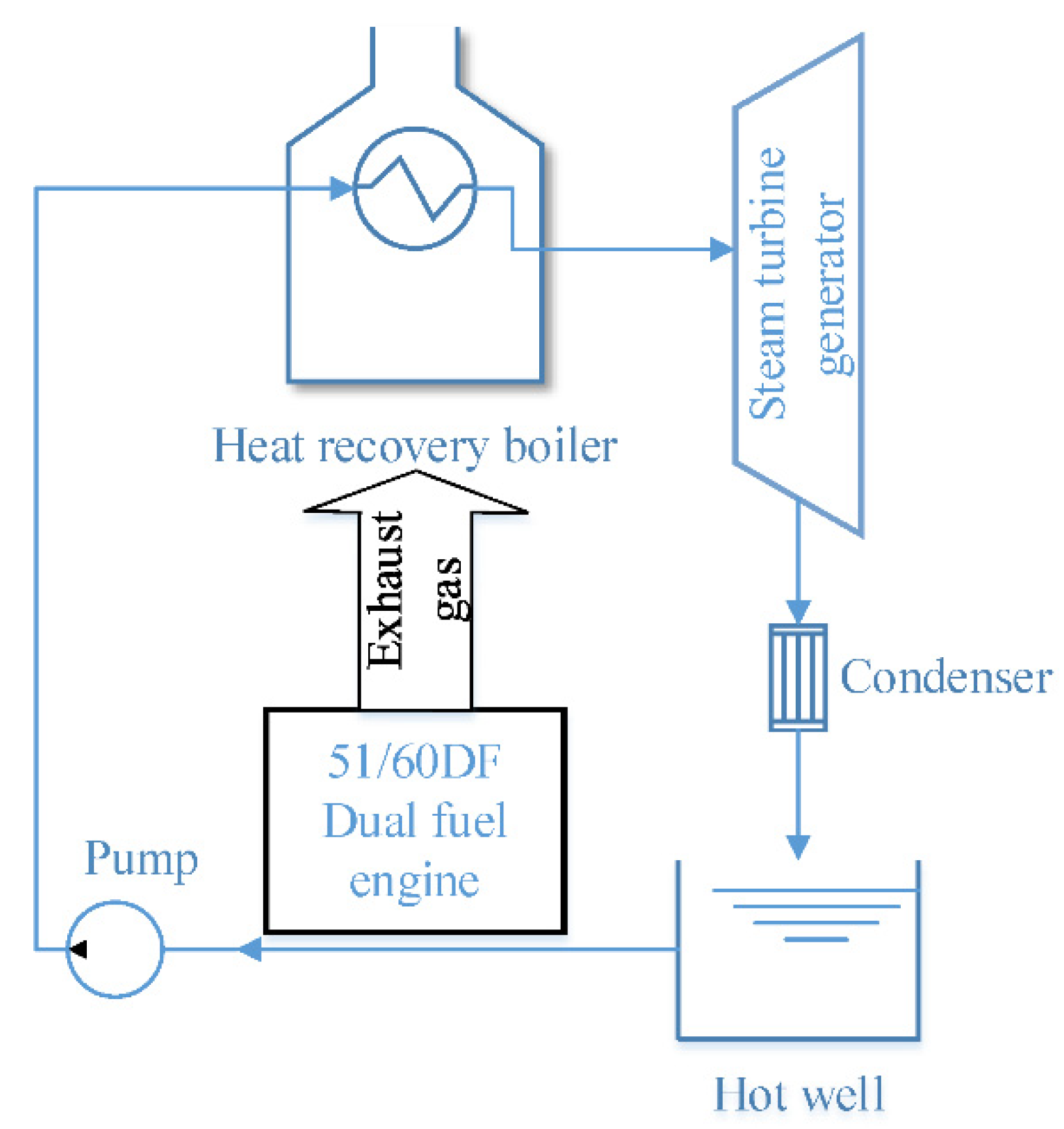
This section focuses mainly on the implementation of the modeling. Section 2.1 discusses the modeling of the DF marine engine. Section 2.2 discusses the modeling of the waste heat boiler. Figure 1 shows the whole DF engine flue gas waste heat recovery system flow chart.
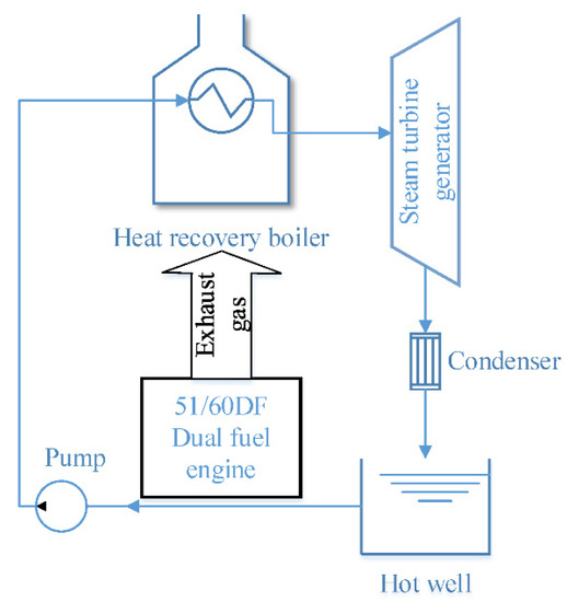
Figure 1.
Flue gas waste heat recovery system.
The exhaust gas waste heat recovery system consists of a DF engine, a waste heat boiler, and a steam turbine. The exhaust gas from the DF engine flows through the waste heat boiler and heats the water in the waste heat boiler, which absorbs the waste heat and vaporizes into superheated steam, driving the steam turbine to generate electricity, and the steam from the steam turbine enters the hot water well after being cooled by the condenser, and the water in the hot water well is pumped to the waste heat boiler through the feed pump, completing the whole cycle.
2.1. DF Engine Modeling Methodology
The engine studied in this paper belongs to a MAN 51/60DF series 8 cylinder 4-stroke DF engine, with a design power of 1000 kW for a single cylinder. DF refers to diesel and natural gas, mainly divided into gas, oil, oil and gas mixture, and other working modes [29].
GT-power is suitable for a spark plug ignition internal combustion engine, compression combustion internal combustion engine, and two-stroke/four-stroke internal combustion engine. This paper uses the MAN 8L51/60DF engine as the research object and was based on GT-power for the simulation. The engine’s main technical parameters are shown in Table 1 [28]. In this paper, the vibe heat release model is used for combustion heat release [24], and the calculation formula is as follows:

Table 1.
Engine technical parameters.
The heat transfer model is used to calculate heat loss, and the complicated heat transfer process is transformed into a heat transfer coefficient model. According to the instantaneous average heat transfer coefficient of the working medium to the cylinder wall [30], the heat transfer coefficient of working medium to the cylinder wall is calculated as follows:
The instantaneous heat transfer coefficient adopts the Woschni formula, which is accurate and straightforward to calculate [31], and the form is as follows:
This engine is a propulsion power device applied to LNG electric propulsion ships. The engine runs at constant speed, which can recover the waste heat of flue gas more stably and effectively than traditional models that directly use a diesel engine as the main propulsion power device of ships.
2.2. Waste Heat Recovery Simulation Methodology
The modular partition modeling of a waste heat boiler was carried out with Simulink, which is divided into a convection zone, metal heat exchange zone, soda, and water zone [32]. The convection zone is taken as an example to establish a mathematical model, and other modules refer to the convection zone.
In mass conservation, the amount of flue gas flowing into the convection zone is equal to the amount of smoke flowing out. The formula is as follows:
In the conservation of energy, the change in the energy in the convection zone is related to the energy of the flue gas entering the convection zone, the energy carried by the flue gas out of convection zone, and the convective heat transfer from the flue gas to the boiler metal wall in the convection zone. The formula is as follows:
where is the energy of the flue gas entering convection zone per unit time, is the energy of the flue gas flowing out of the convection zone per unit time, is the convective heat exchange between the flue gas and the metal wall of the boiler per unit time, and is the flue gas energy of convection zone. Steady-state algebraic equations are used to describe the variation in the working conditions of the steam turbine. When the working conditions of the steam turbine change, the steam flow of the steam turbine can be calculated by the Flugel formula [33]. The formula is as follows:
where is the steam mass flow rate, is the steam mass flow rate under design working conditions, is the inlet steam temperature, is the inlet steam temperature under design working conditions, is the inlet steam pressure, is the outlet steam pressure, is the inlet steam pressure under design working conditions, and is the outlet steam pressure under design working conditions.
The outlet enthalpy of a steam turbine is derived from the ideal enthalpy by the following procedure, and then corrected by the efficiency, whose inlet entropy can be determined by the other parameters of the inlet steam. The formula is as follows:
where is the steam outlet’s enthalpy, is the steam inlet’s enthalpy, is the stage efficiency, and is the ideal steam outlet’s enthalpy.
The output power of the steam turbine is the power generation power of flue gas waste heat [34]. The formula is as follows:
Simulink allows modeling and simulation of continuous and discrete systems based on the mathematical logic that has been constructed. Simulink is used to simulate the waste heat boiler. The exhaust temperature of the engine determines the steam temperature of the waste heat boiler. The exhaust gas turbocharger outlet temperature of the DF engine studied in this paper is 326 °C under full load gas mode, regarded as the flue gas inlet temperature of the waste heat boiler. The steam temperature is set to 270 °C. Considering the temperature drop effect of the pipeline, the intake temperature of the steam turbine needs to be reduced by 5 °C on this basis. The steam pressure of the waste heat boiler needs to refer to the inlet pressure corresponding to the inlet temperature of the turbine. Under the condition of satisfying the turbine’s relative internal efficiency and exhaust humidity, the steam pressure is selected as 0.7 MPa [35]. In order to improve the utilization rate of waste heat, it is necessary to reduce the exhaust temperature of the waste heat boiler as much as possible. However, the exhaust temperature of the waste heat boiler affects the equivalent thermal efficiency and is limited by the acid dew point of flue gas and smoke wind resistance. When the temperature is too low, sulfur retention produces sulfur corrosion. After comprehensive consideration, the exhaust temperature of the waste heat boiler is chosen as 170 °C [36]. The design parameters are shown in Table 2.
Table 2.
Main technical parameters of the waste gas boiler.
3. Modeling and Calibration
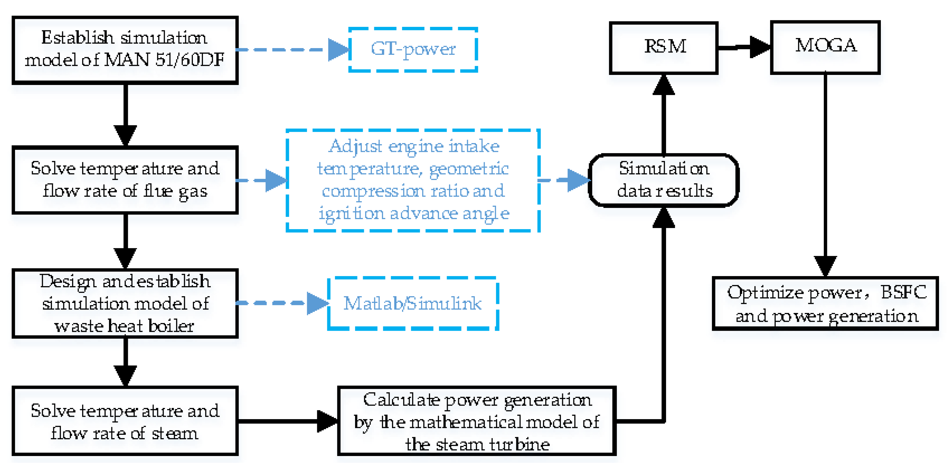
The research flow chart is shown in Figure 2. The research of flue gas waste heat mainly focuses on improving the waste heat boiler’s combined cycle and structure parameters. This study aimed to analyze the influence of optimized diesel engine body parameters on the energy recovery of flue gas. The content of this paper is as follows. In the first part, the modeling and simulation software GT-Power was used to establish the simulation model of a MAN 8L 51/60DF large marine four-stroke DF engine, and the model is calibrated. Three input parameters, the intake temperature, compression ratio, and pilot fuel injection timing, were selected for simulation. The second part used MATLAB/Simulink to establish a waste heat boiler model and calculated the temperature and flow of steam. According to the temperature and flow of the steam and the mathematical model of the steam turbine, the flue gas waste heat power generation was calculated. The third part used RSM to build the objective surrogate model based on simulation data and used MOGA for optimization.
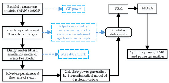
Figure 2.
Summary of the working routine.
3.1. Simulation Model of the DF Engine
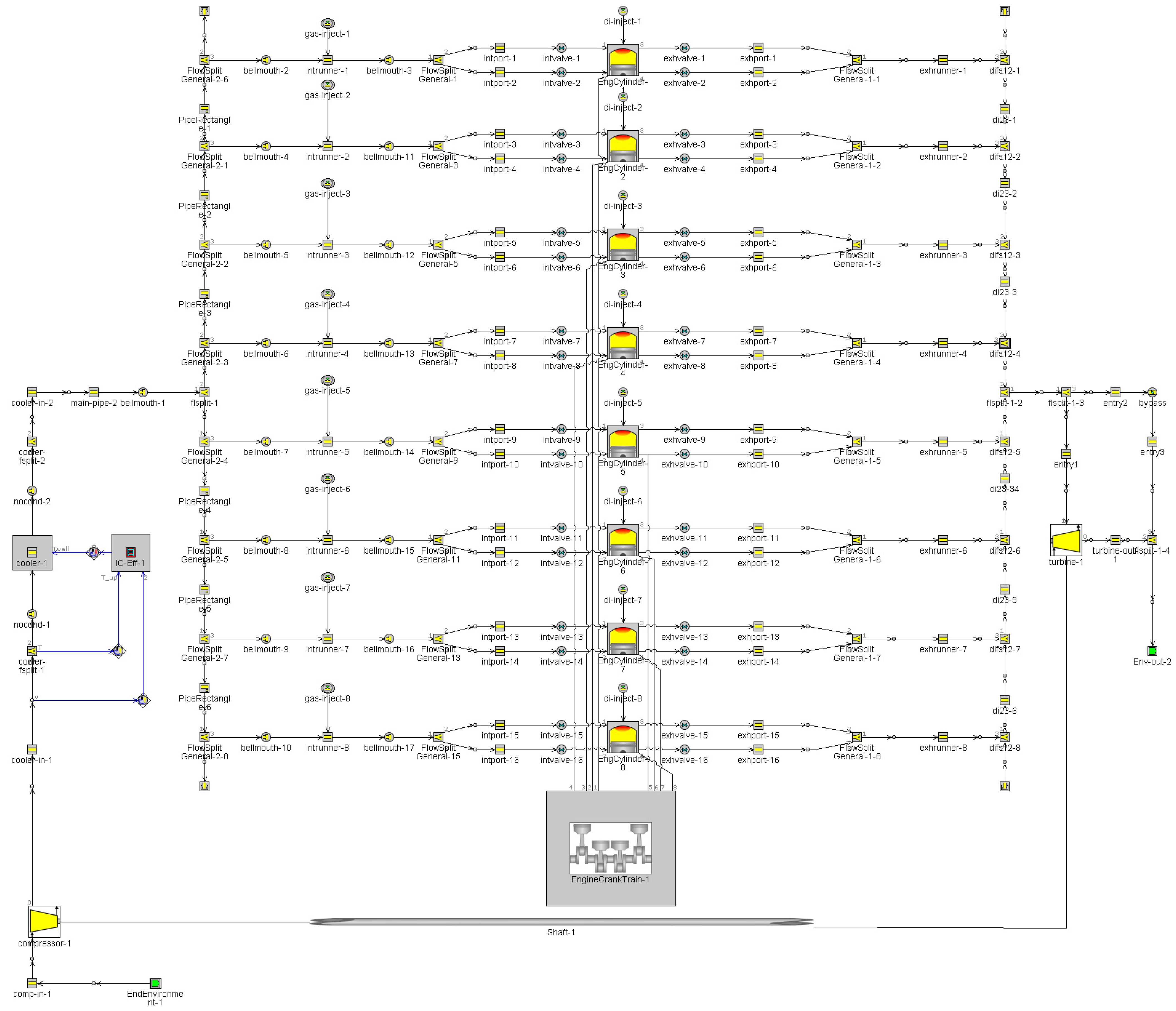
The DF engine model is shown in Figure 3. The system comprises a compressor, intercooler, intake pipe, cylinder block, exhaust pipe, and turbocharger [37]. The fuel injection method adopted is port fuel injection and direct injection (PFI + DI) [38]. The exhaust gas turbocharger used in the GT-Power model is a MAN Diesel & Turbo TCA55-turbocharger. The compressor map of the TCA55-turbocharger is described in [39]. It contains the volume flow rate and pressure ratio, which are important for modeling.
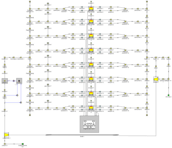
Figure 3.
MAN 8L51/60DF engine GT-Power model.
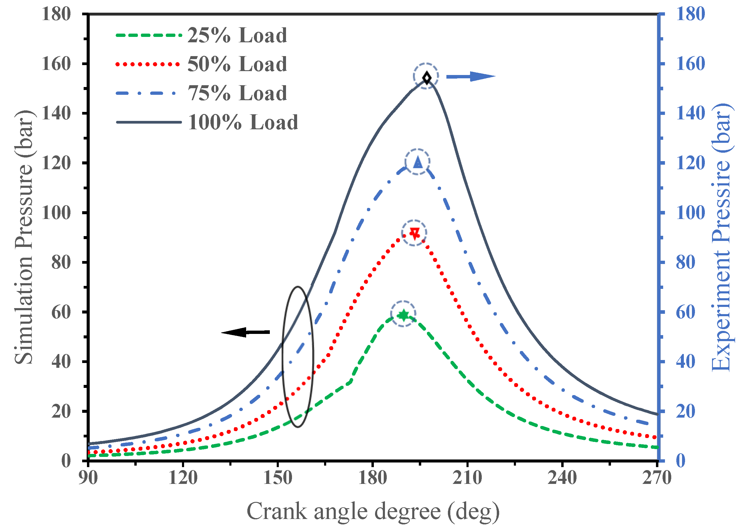
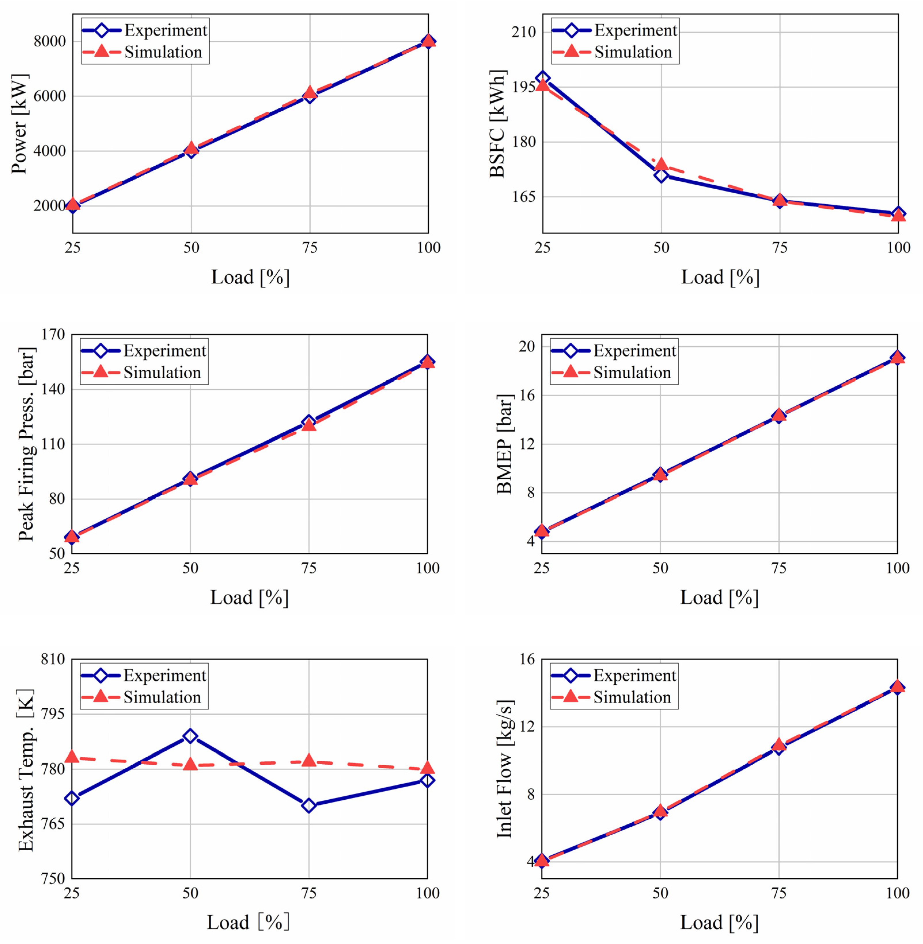
The factory test report [28] was referred to. Table 3 shows the errors of the main parameters under different loads in gas mode. Figure 4 shows the comparison between the simulation values and the experiment values of this DF engine in gas mode. Figure 5 shows the experiment cylinder pressure and simulation cylinder pressure of this DF engine in gas mode. It indicates that the established one-dimensional (1-D) GT-power model runs accurately in gas mode. The errors between the simulation values and experimental values of the main parameters are within 2%, which indicates that the established 1-dimensional simulation model can be used for further studies [24].
Table 3.
Calculation error of the gas mode.
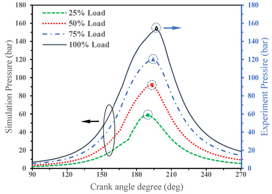
Figure 4.
Comparison of the simulated values and experimental values in gas mode.
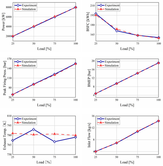
Figure 5.
Comparison of the experimental and simulated cylinder pressure curve in gas mode.
3.2. Simulation Model of the Waste Heat Boiler
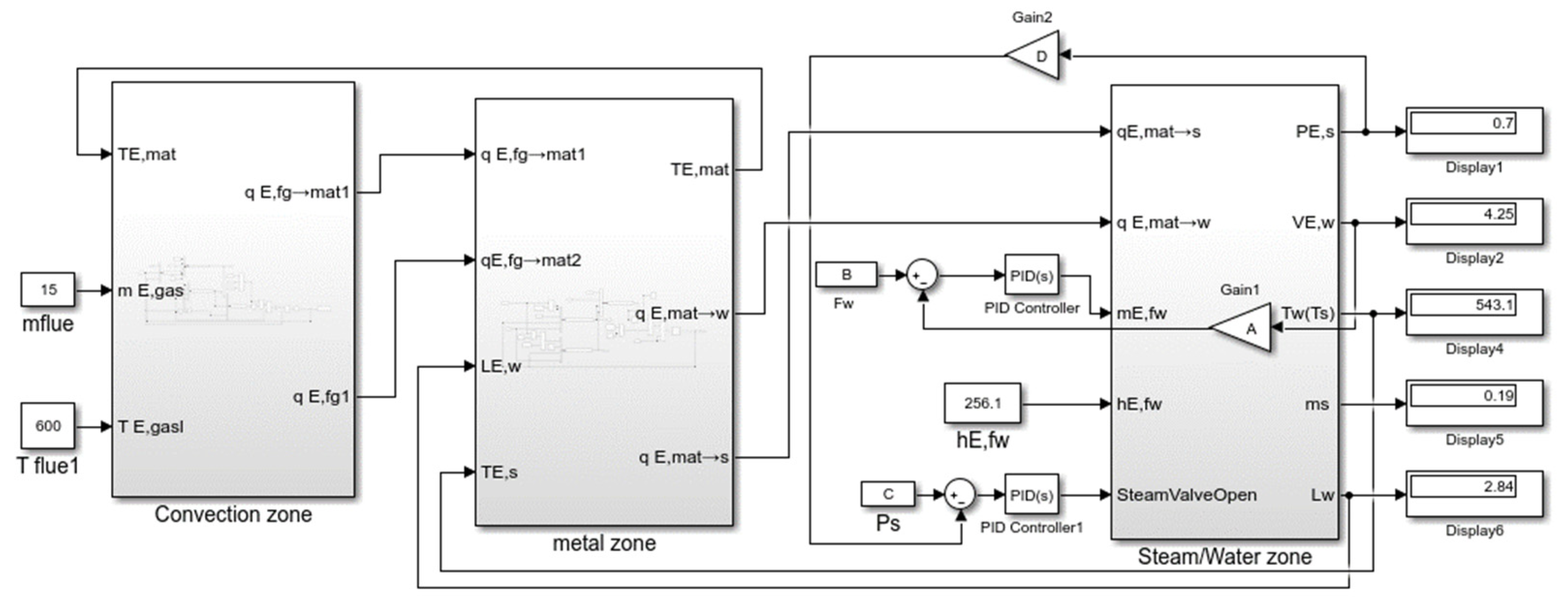
According to the theoretical model, the waste heat boiler under the Simulink environment was established as shown in Figure 6.
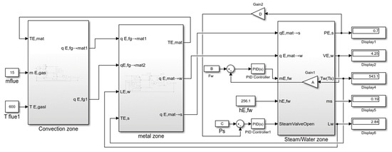
Figure 6.
Simulink model of the waste heat boiler.
As shown in Table 4, when the engine is under full load, the simulation results of the waste heat boiler are compared with the design value, and the relative errors of the superheated steam pressure, temperature, flow rate, and other main parameters are within 3%, indicating that the calculation accuracy of the simulation model of the waste heat boiler built meets the requirements of the engineering calculation [40].
Table 4.
Calculation error of the steam parameters.
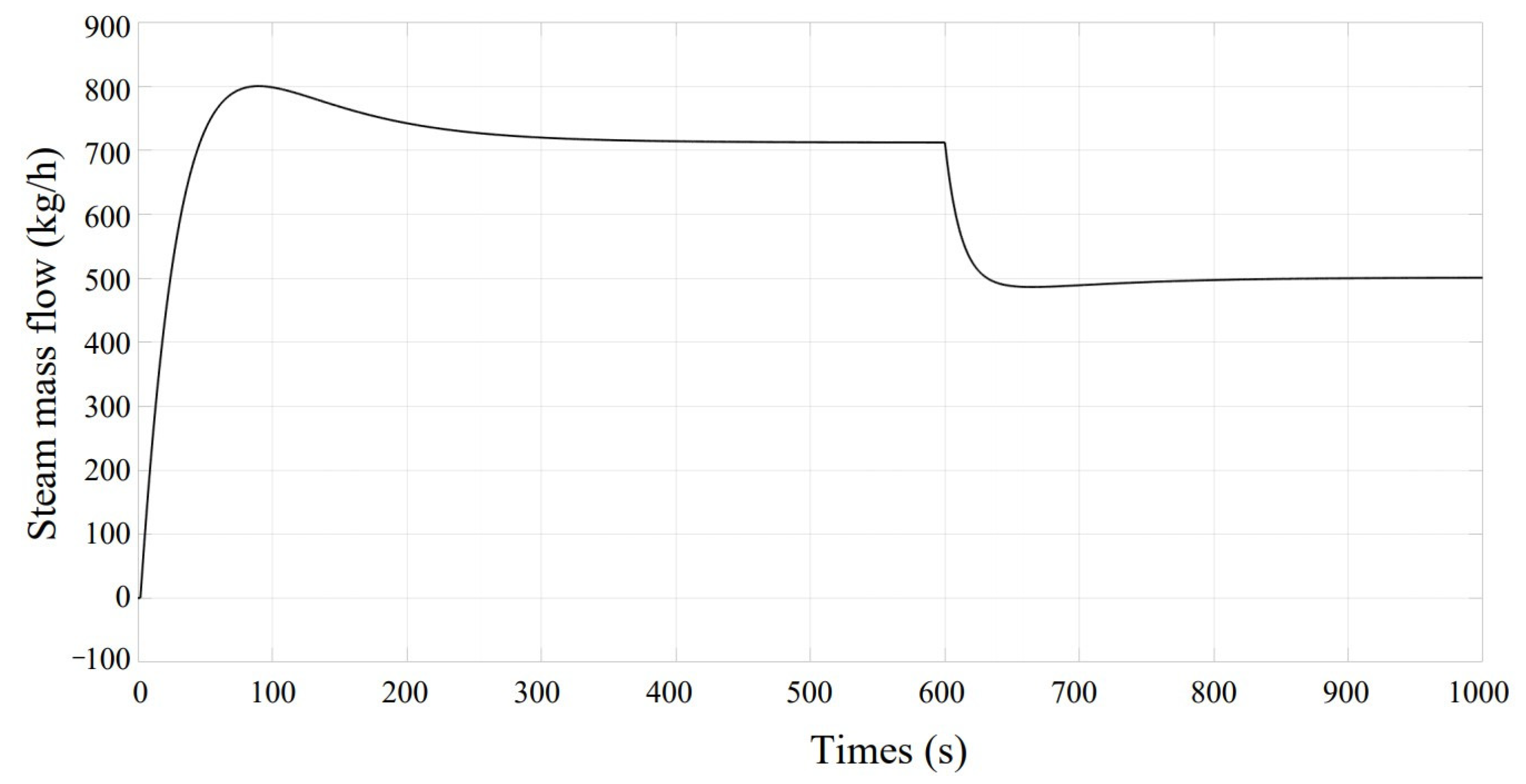
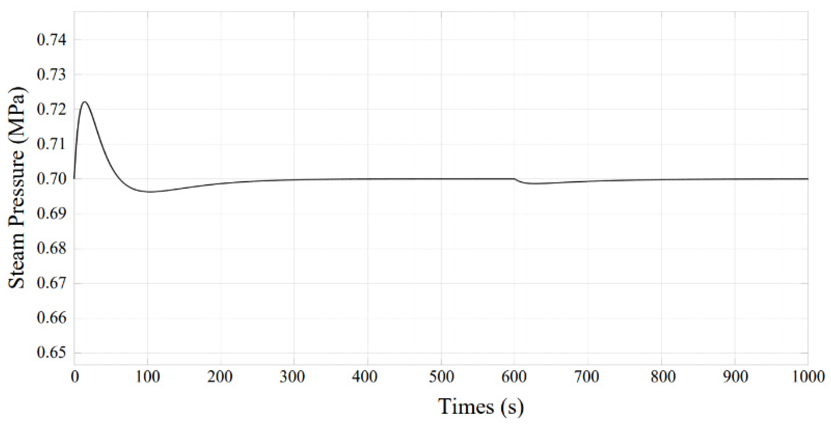
According to the built model, the simulation parameters were set: the simulation time was 1000 s, the simulation solution method was the fixed step, the solver was ode4 (Runge-Kutta), and the fundamental sample time was 0.1. At 600 s, load disturbance was added. As shown in the Figure 7 and Figure 8, parameters, such as the steam pressure and flow rate, can converge quickly and reach a stable operating condition.
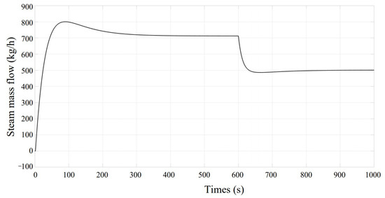
Figure 7.
Steam mass flow dynamic simulation diagram.
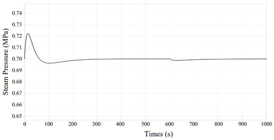
Figure 8.
Steam mass flow and steam pressure dynamic simulation diagram.
The 1-D GT-Power simulation model established above was run and calculated to obtain the engine flue gas parameters, including the flue gas temperature, flue gas flow rate, and flue gas pressure, and the energy contained in the flue gas per unit time was calculated. The air and flue gases are considered as the ideal gas, and the heat capacity as a monovalent function of the temperature. The flue gas temperature, flue gas mass flow, and flue gas energy of the engine were used as the input of the waste heat boiler model, and the parameters, such as the superheated steam temperature and mass flow rate, were calculated by running MATLAB. The output power of the steam turbine was derived by calculating the enthalpy difference between the import and export using the mathematical model of the steam turbine, and the flue gas waste heat generation capacity of the engine was derived. Flue gas waste heat power generation is determined by steam turbine performance, and steam turbine performance is influenced by the exhaust temperature of the DF engine. When the exhaust gas temperature increases, the amount of steam produced by the waste heat boiler increases, and the steam temperature also increases, resulting in a corresponding increase in the steam enthalpy, which converts more electricity when the steam drives the steam turbine. The pressure of the waste heat boiler also affects the power generation performance when the pressure of the waste heat boiler increases. As the pressure in the boiler rises, the amount of gas produced by the waste heat boiler gradually decreases, and the exhaust temperature of the waste heat boiler and the output power of the steam turbine gradually increases. Moreover, the power output becomes gradually smoother as the pressure continues to increase [41].
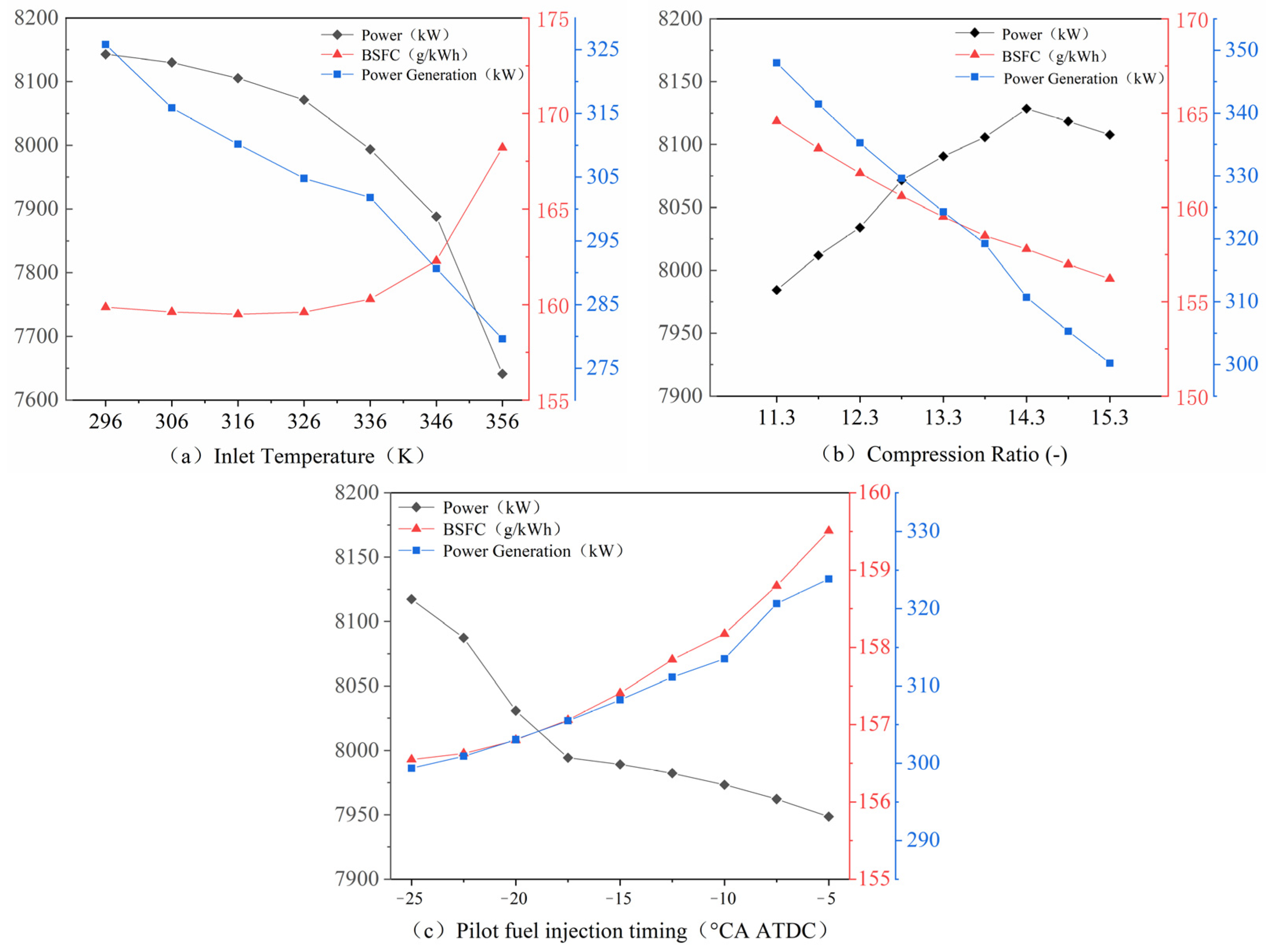
As shown in Figure 9, there is a significant correlation between the intake temperature, compression ratio, pilot fuel injection timing and power, BSFC, and waste heat generation of DF engines. So, the intake temperature, geometry compression ratio, and pilot fuel injection timing are = independent variable parameters while power, BSFC, and power generation are the objective functions. The influence of independent variable parameters on the objective function is analyzed below.
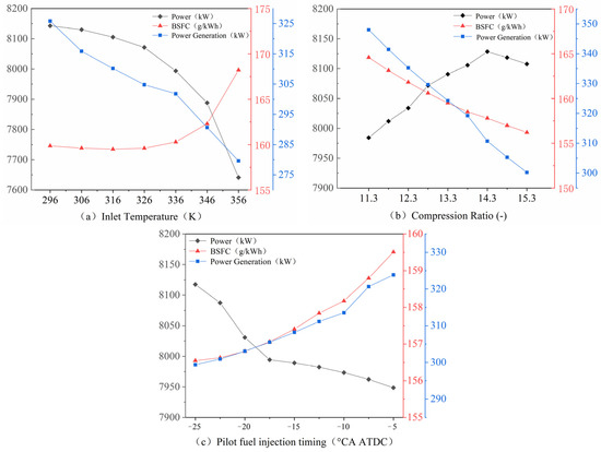
Figure 9.
Influence trend of the objective function.
3.3. Prediction Model Modeling
RSM takes into account the experimental random error. It puts the complex unknown functional relationship with a simple primary or quadratic polynomial model for fitting. The calculation is relatively simple, and the obtained prediction model is continuous, so it is very suitable for the study described in this paper. RSM is used to analyze the BSFC, power, and flue gas waste heat generation. The general expression of the mathematical model [42] is as follows:
where is the response; are numeric values of the factors; the terms , , , and are regression coefficients; and is the error. The determination coefficient is calculated by the following formula:
where is a fully fitted measure that reflects how well the response surface meets the given data, which must be greater than 0.9. The adjustment coefficient of determination is as follows:
where is the degree of correlation between all independent variables and dependent variables, and the regression effect is better when it is close to 1. The formula used for evaluating the predictive power of a model is as follows:
where Predicted- is a measurement of the amount of variation in new data explained by the model, which must be greater than 0.8. The SS, PRESS, and represent the sum of squares, sum of prediction errors, and degree of freedom.
The DOE experiment design was carried out for BSFC, power, and flue gas waste heat generation, and the response surface surrogate model was established. The standard set values include an intake temperature of the engine of 316 K, geometric compression ratio of 13.3, and pilot fuel injection timing of −15 °CA after top dead center (ATDC). The intake temperature varies from 296 to 356 K, the compression ratio from 11.3 to 17.3, and the pilot fuel injection timing from −25 to −5 °CA ATDC.
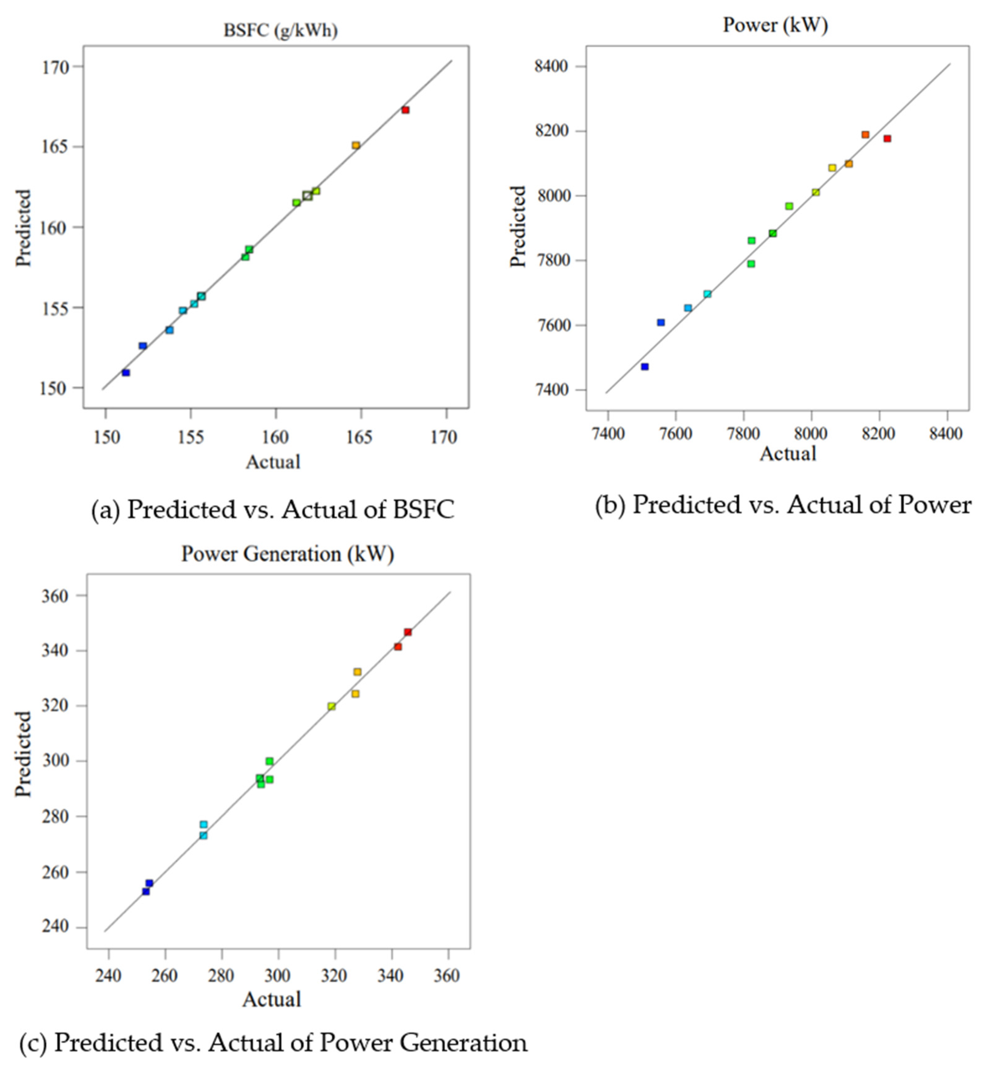
Table 5 shows the analysis of variance (ANOVA) table [25], where is the intake temperature, is the factor of compression ratio, and is the pilot fuel injection timing. Among the ANOVA, BSFC is 0.9977, and the power and flue gas waste heat generation are 0.9819 and 0.9940, respectively, which are larger than 0.9, indicating that the response surface is consistent with the given data [43]. The difference between the predicted and actual values is the residual. As shown in Figure 10, the predicted and actual values of several essential engine indicators are proportional, indicating that the model prediction is accurate.
Table 5.
ANOVA table for BSFC, power, and power generation.
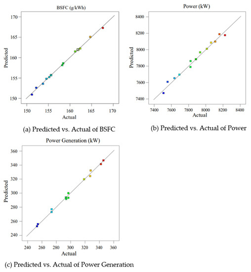
Figure 10.
Comparison of the predicted and actual values.
The BSFC model based on RSM is as follows:
The power model is as follows:
The generation model of the flue gas waste heat is as follows:
4. Result and Discussion
4.1. Multi-Objective Optimization
The response surface plots of the above parameters to the objective function are shown in Figure 11, Figure 12 and Figure 13.
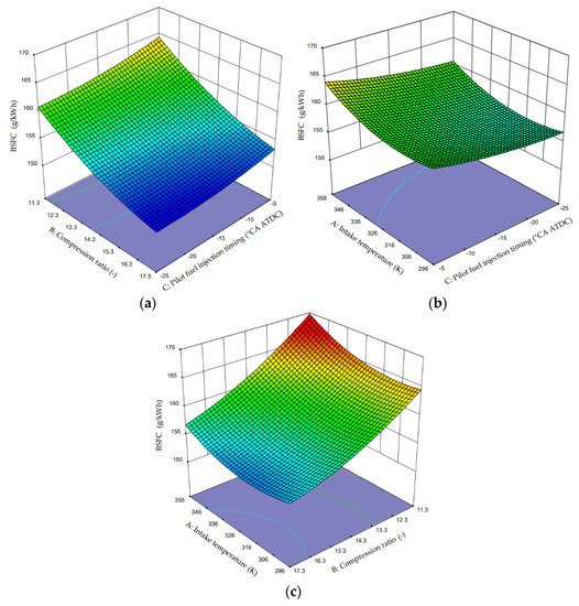
Figure 11.
Surface plot of BSFC with input variables. (a) Intake temperature = 316 K; (b) Compression ratio = 13.3; (c) Pilot fuel injection timing = −15 °CA ATDC.

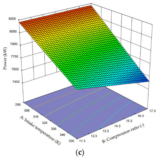
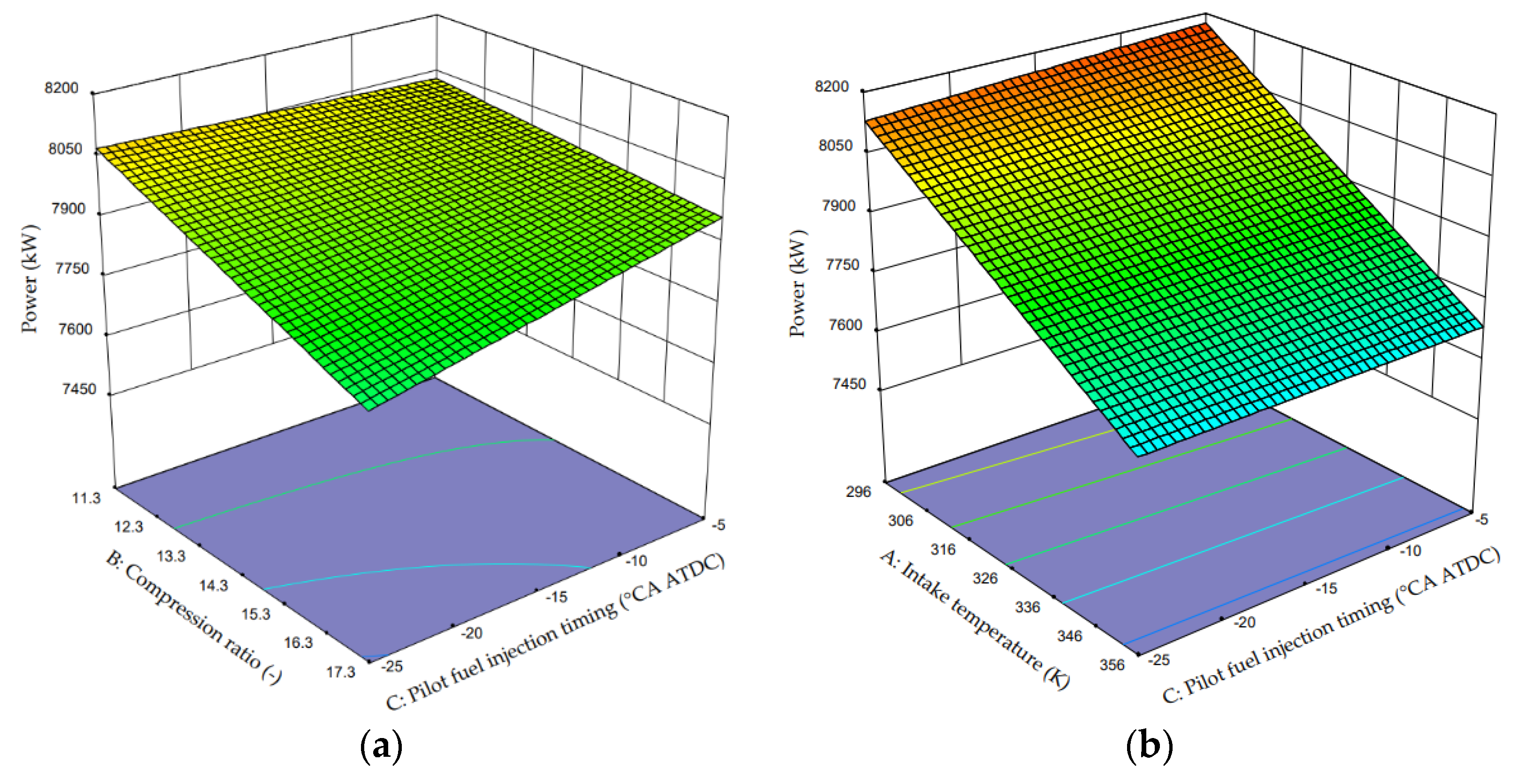
Figure 12.
Surface plot of power with input variables. (a) Intake temperature = 316 K; (b) Compression ratio = 13.3; (c) Pilot fuel injection timing = −15 °CA ATDC.
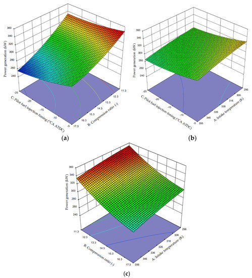
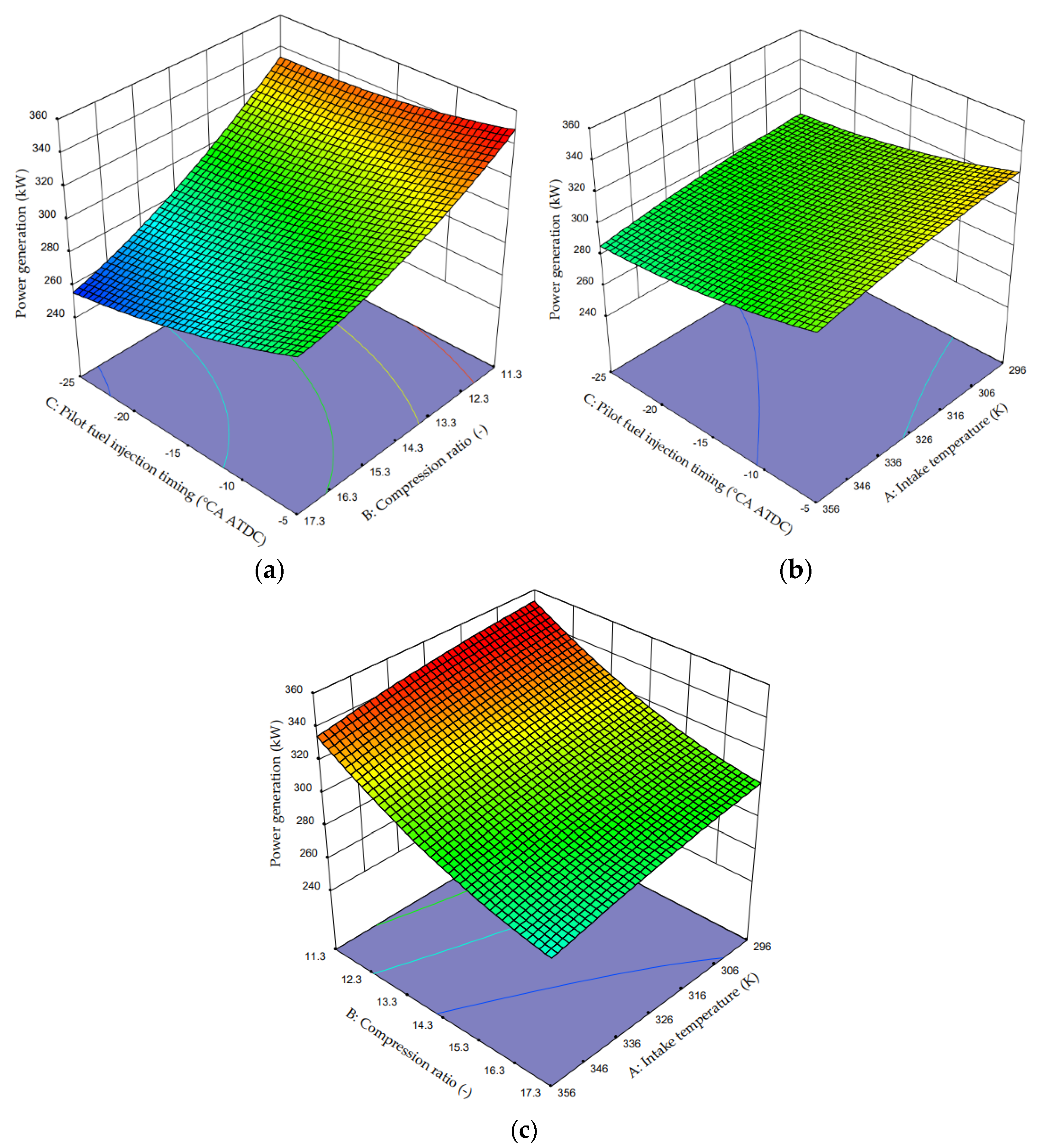
Figure 13.
Surface plot of power generation with input variables. (a) Intake temperature = 316 K; (b) Compression ratio = 13.3; (c) Pilot fuel injection timing = −15 °CA ATDC.
The above shows that with the increase in the compression ratio, the flue gas waste heat generation gradually decreases. With the increase in the intake temperature, the power generation decreases. With the advance of the pilot fuel injection timing, the power generation gradually decreases. Similarly, the analysis of the impact on power and BSFC will not be repeated here. We need to consider not only the identification of the largest possible flue gas waste heat generation but also consideration of the engine’s BSFC, power, and other performance parameters. Due to the intake temperature and compression ratio, pilot fuel injection timing has a significant influence on the engine performance parameters, so we need to guarantee the optimal power settings as for the engine performance. Therefore, MOGA is required.
4.2. Impact Analysis of the Operating Parameters
Genetic algorithms are mainly applied to single-objective optimization problems, but many problems have multiple objective functions, so it is necessary to use MOGA. For multi-objective optimization problems, the objective is to find all possible tradeoff solutions between multiple objective functions. The MOGA can show the pareto optimal solution, and then a pareto optimal solution is chosen according to the preference. So, the MOGA is suitable for the research described in this paper.
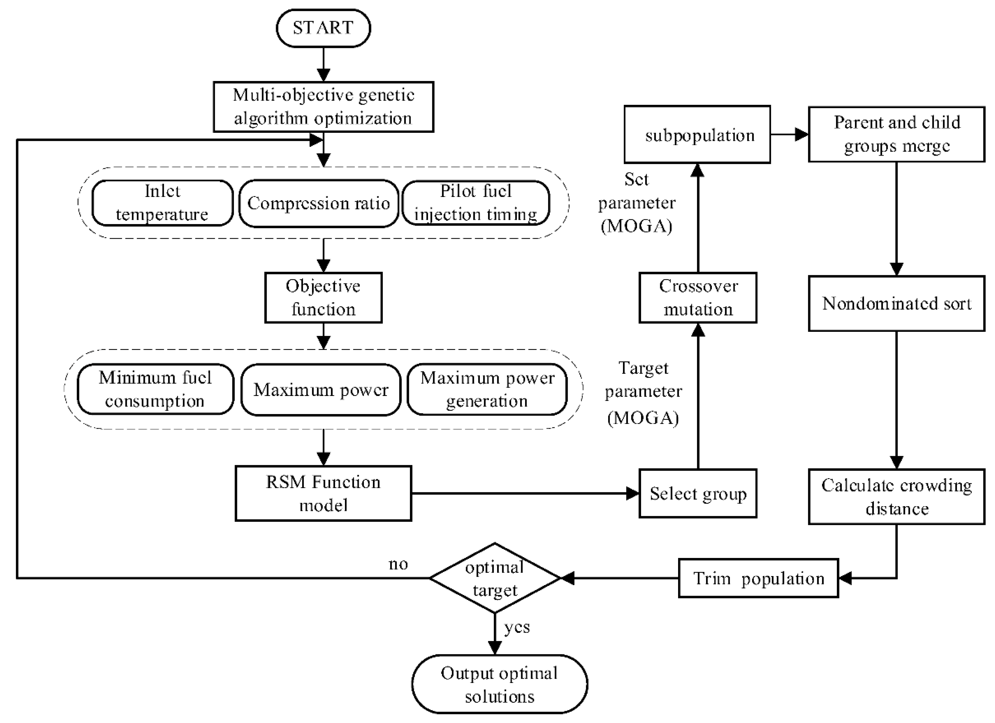
In this paper, a multivariable strategy and multi-objective optimization algorithm are combined to study the optimization of the engine performance and flue gas waste heat recovery. The flow chart is shown in Figure 14.
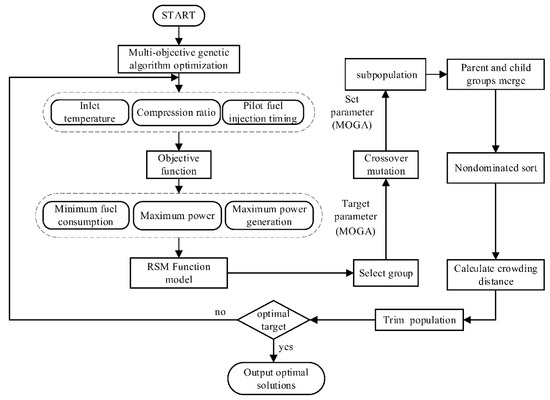
Figure 14.
Multi-objective optimization flow chart.
The purpose of this study is to optimize the intake temperature, compression ratio, and pilot fuel injection timing by MOGA to achieve the highest power and maximum flue gas heat. The model established by the above RSM is used as the surrogate model of the DF engine, and the equation is as follows [44]:
The adopted MOGA can identify the minimum value of the target, so the maximum power and maximum flue gas generation need to be transformed into the minimum optimization problem. Therefore, the power and flue gas generation in the subsequent pareto front figure are negative values. The MOGA is implemented using MATLAB, and its parameters are shown in Table 6. Genetic algorithms also introduce system constraints to ensure that the algorithm will converge to viable solutions [45]. The constraints are as follows:
Table 6.
Parameters used in optimization.
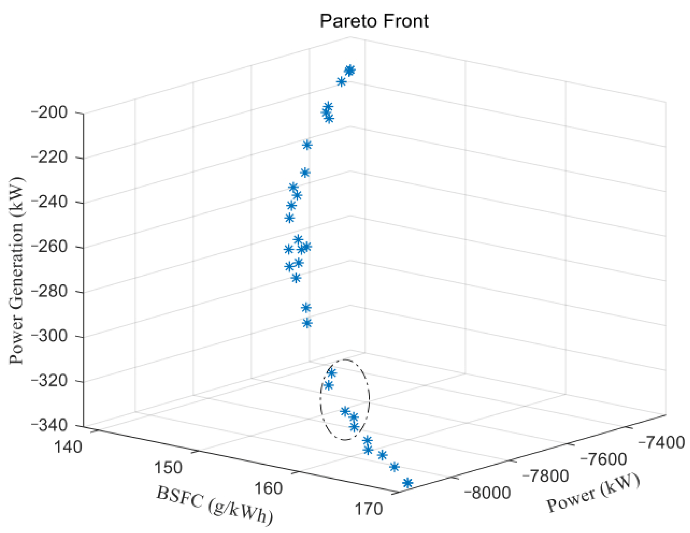
As shown in Figure 15, it can be seen in the pareto frontier surface plot that the MOGA used in this paper is suitable for the MOGA problem under study, i.e., to achieve the objectives of maximum power, maximum flue gas generation, and minimum BSFC. The solid points indicate that the solutions are pareto optimal solutions, and all pareto optimal solutions constitute the pareto optimal solution set, which are stored in the MATLAB workspace. Here, it should be emphasized again that the power and flue gas generation are negative values transformed to find the optimal value. The actual results are taken as positive values.
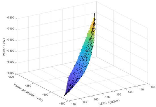
Figure 15.
Pareto front with data (the absolute value of the negative sign in the graph represents the actual value).
The global optimal solution cannot be found due to the large value of the population in the above section. Therefore, the population number is reduced to 100, and the optimal solution set is shown in Figure 16. When the power and power generation increase, the BSFC also increases sharply, and the increase in BSFC of marine engines is not desired by ship operators and does not conform to the concept of energy-saving and emission reduction. So, we cannot just seek the maximum power and flue gas waste heat generation. We need to seek the maximum power and flue gas waste heat generation within the acceptable BSFC range. Therefore, the data points circled with the red dashed line in Figure 16 are the artificially selected optimal solution set. According to the bench test report, the constraints are power greater than 8000 kW and BSFC less than 160.37 g/kWh. The optimal solutions that satisfy the constraints are organized as shown in Table 7.

Figure 16.
MOGA optimal solution set (the absolute value of the negative sign in the graph represents the actual value).
Table 7.
MOGA optimization results.
As the optimal solution cannot be seen intuitively in the three-dimensional Pareto front diagram, the two-dimensional Pareto front diagram about power and BSFC is presented as shown in Figure 17. The data marker points in the figure are considered as the selected optimal solution. When the intake temperature of the DF engine is set at 306.18 K, the compression ratio is set at 14.4, and the pilot fuel injection timing is set at −16.68 °CA ATDC, the corresponding BSFC is 155.53 g/kWh, and the power is 8024.91 kW. At the same time, 273.31 kW of flue gas waste heat generation was obtained.
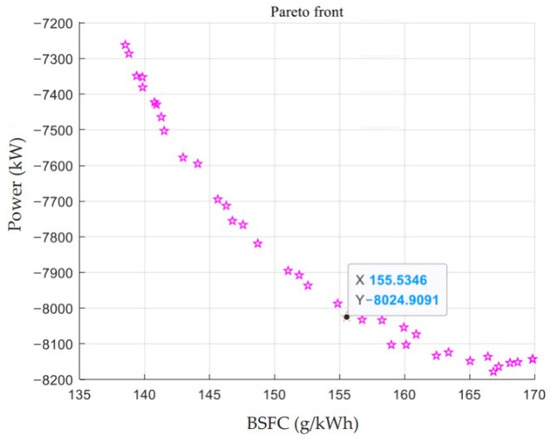
Figure 17.
Pareto optimal front (the absolute value of the negative sign in the graph represents the actual value).
The optimal solution was brought into the model as an input parameter for the recalculation, and BSFC was 155.18 g/kWh, power was 8025.62 kW, and the residual power generation of the flue gas was 280.98 kW. The exhaust gas waste heat power generation before the optimization was 260.95 kW. Table 8 displays the same parameter settings and the simulation results. The power, BSFC, and power generation agree with the predicted values. Compared with another study [46] on waste heat recovery from engine exhaust gas with similar engine power to this paper, the engine power in this study was 9960 kW, and the theoretical maximum power recovery was 1072.4 KW. However, this study did not take BSFC and the variation in the engine power into account. In this paper, multiple optimization objectives, such as engine performance, are within a reasonable constraint.
Table 8.
Comparison between the optimization results of MOGA and simulation results.
5. Conclusions
This paper optimized the performance of a marine four-stroke DF engine MAN 51/60DF based on MOGA, including the engine BSFC, power, and flue gas waste heat generation.
- The 1-D model of the DF engine was established based on the GT-Power simulation modeling tool. The simulation data were checked and verified before the optimization study of the DF engine, and the maximum error was 1.96% in gas mode. Then, the main parameters of the waste heat boiler were designed, the Simulink simulation model was established, and the power generation of flue gas waste heat was calculated according to the mathematical model of the steam turbine.
- The effects of the intake temperature, compression ratio, and pilot fuel injection timing on flue gas waste heat generation in the DF engine gas mode were studied. Through the analysis of the simulation data, it can be seen that with the increase in the intake temperature, the BSFC decreased first and then increased, the power decreased gradually, and the power generation decreased gradually. With the decrease in the compression ratio, the BSFC, power, and power generation increased gradually. With the advance of the pilot fuel injection timing, BSFC, power, and power generation were gradually reduced.
- MOGA was used to obtain the optimal parameter settings under the condition of maximum power and flue gas waste heat generation and minimum BSFC. First, RSM transformed the data into a nonlinear regression model for the analysis and optimization. The optimal solution set was obtained by optimizing the algorithm, and then the optimal solution was selected artificially. The reduction of BSFC is most important, so the final optimal solution was 306.18 K (intake temperature), 14.4 (compression ratio), and −16.68 °CA ATDC (pilot fuel injection timing). This corresponded to 155.18 g/kWh (BSFC), which was reduced by 3.24%, 8025.62 kW (power), and increased by 0.32%. At the same time, an additional 280.98 kW (flue gas waste heat generation) was obtained.
In conclusion, this study provides a methodology for the modeling and optimization of four-stroke DF engines for ships. The results contribute to a better understanding of the effects of operating parameters on performance and exhaust gas waste heat utilization. RSM was applied to engine performance and exhaust gas waste heat utilization, and combined with the MOGA optimization algorithm, the engine parameter settings were derived under the condition that performance and exhaust gas waste heat generation were satisfied.
In future work, the operating parameters of the DF engine under full load will be optimized by machine learning, including linear regression, support vector machine, and Gaussian process regression. Then, their optimization results will be compared.
Author Contributions
Conceptualization, D.M. and H.W.; methodology, D.M.; software, D.M.; validation, D.M., H.G. and H.W.; formal analysis, H.G.; investigation, D.M., H.G. and H.W.; re-sources, H.G.; data curation, H.W., H.G.; writing—original draft preparation, D.M.; writing—review and editing, H.G. and H.W.; visualization, H.G.; supervision, H.G.; project administration, H.G.; funding acquisition, H.G. All authors have read and agreed to the published version of the manuscript.
Funding
This research was funded by National Natural Science Foundation of China(grant number U1905212), as well as “the Fundamental Research Funds for the Central Universities” (grant number 3132019315).
Institutional Review Board Statement
Not applicable.
Informed Consent Statement
Not applicable.
Data Availability Statement
The data used to support the findings of this study are available from the corresponding author upon request.
Conflicts of Interest
The authors declare no conflict of interest.
References
- Sun, X.; Liu, H.; Duan, X.; Guo, H.; Li, Y.; Qiao, J.; Liu, Q.; Liu, J. Effect of Hydrogen Enrichment on the Flame Propagation, Emissions Formation and Energy Balance of the Natural Gas Spark Ignition Engine. Fuel 2022, 307, 121843. [Google Scholar] [CrossRef]
- Chen, Z.; Wang, L.; Wang, X.; Chen, H.; Geng, L.; Gao, N. Experimental Study on the Effect of Water Port Injection on the Combustion and Emission Characteristics of Diesel/Methane Dual-Fuel Engines. Fuel 2022, 312, 122950. [Google Scholar] [CrossRef]
- Wen, S.; Qu, X.; Zhu, Y.L. Study on Recovery System for Marine Diesel Engine Waste Heat. Adv. Mater. Res. 2014, 912–914, 795–798. [Google Scholar] [CrossRef]
- Stoumpos, S.; Theotokatos, G.; Boulougouris, E.; Vassalos, D.; Lazakis, I.; Livanos, G. Marine dual fuel engine modelling and parametric investigation of engine settings effect on performance-emissions trade-offs. Ocean Eng. 2018, 157, 376–386. [Google Scholar] [CrossRef] [Green Version]
- Akman, M.; Ergin, S. Thermo-Environmental Analysis and Performance Optimisation of Transcritical Organic Rankine Cycle System for Waste Heat Recovery of a Marine Diesel Engine. Ships Offshore Struct. 2020, 16, 1104–1113. [Google Scholar] [CrossRef]
- Zhao, R.; Zhuge, W.; Zhang, Y.; Yong, Y.; Li, Z. Parametric study of power turbine for diesel engine waste heat recovery. Appl. Therm. Eng. 2014, 67, 308–319. [Google Scholar] [CrossRef]
- Manzela, A.A.; Hanriot, R.M.; Cabezas-Gomez, R.; Sodre, R.R. Using engine exhaust gas as energy source for an absorption refrigeration system. Appl. Energy 2010, 87, 1141–1148. [Google Scholar] [CrossRef]
- Fernández-Seara, J.; Vales, A.; Vázquez, M. Heat recovery system to power an onboard NH3-H2O absorption refrigeration plant in trawler chiller fishing vessels—ScienceDirect. Appl. Therm. Eng. 1998, 18, 1189–1205. [Google Scholar] [CrossRef]
- Kim, Y.; Negash, A.; Shamsi, S.S.M.; Shin, D.; Cho, G. Experimental Study of a Lab-Scale Organic Rankine Cycle System for Heat and Water Recovery from Flue Gas in Thermal Power Plants. Energies 2021, 14, 4328. [Google Scholar] [CrossRef]
- Lion, S.; Taccani, R.; Vlaskos, I.; Scrocco, P.; Vouvakos, X.; Kaiktsis, L. Thermodynamic analysis of waste heat recovery using Organic Rankine Cycle (ORC) for a two-stroke low speed marine Diesel engine in IMO Tier II and Tier III operation. Energy 2019, 183, 48–60. [Google Scholar] [CrossRef]
- Mohammed, A.G.; Mosleh, M.; El-Maghlany, W.M.; Ammar, N.R. Performance analysis of supercritical ORC utilizing marine diesel engine waste heat recovery. Alex. Eng. J. 2020, 59, 893–904. [Google Scholar] [CrossRef]
- Douvartzides, S.; Karmalis, I. Working fluid selection for the Organic Rankine Cycle (ORC) exhaust heat recovery of an internal combustion engine power plant. In IOP Conference Series: Materials Science and Engineering; IOP Publishing: Bristol, UK, 2016; Volume 161, p. 12087. [Google Scholar] [CrossRef] [Green Version]
- Teng, D.; Jia, X.; Yang, W.; An, L.; Shen, G.; Zhang, H. Experimental Investigation into Flue Gas Water and Waste Heat Recovery Using a Purge Gas Ceramic Membrane Condenser. ACS Omega 2022, 6, 4956–4969. [Google Scholar] [CrossRef] [PubMed]
- Ouyang, T.; Huang, G.; Su, Z.; Xu, J.; Zhou, F.; Chen, N. Design and optimisation of an advanced waste heat cascade utilisation system for a large marine diesel engine. J. Clean. Prod. 2020, 273, 123057. [Google Scholar] [CrossRef]
- Li, Y.; Jia, M.; Xu, L.; Bai, X. Multiple-objective optimization of methanol/diesel dual-fuel engine at low loads: A comparison of reactivity controlled compression ignition (RCCI) and direct dual fuel stratification (DDFS) strategies. Fuel 2020, 262, 116673. [Google Scholar] [CrossRef]
- Wang, H.; Ji, C.; Shi, C.; Ge, Y.; Meng, H.; Yang, J.; Chang, K.; Wang, S. Comparison and evaluation of advanced machine learning methods for performance and emissions prediction of a gasoline Wankel rotary engine. Energy 2022, 248, 123611. [Google Scholar] [CrossRef]
- Wang, H.; Ji, C.; Shi, C.; Ge, Y.; Hao, M.; Yang, J.; Ke, C.; Wang, S. Development of cyclic variation prediction model of the gasoline and n-butanol rotary engines with hydrogen enrichment. Fuel 2021, 299, 120891. [Google Scholar] [CrossRef]
- Wang, H.; Ji, C.; Su, T.; Shi, C.; Ge, Y.; Yang, J.; Wang, S. Comparison and implementation of machine learning models for predicting the combustion phases of hydrogen-enriched Wankel rotary engines. Fuel 2022, 310, 122371. [Google Scholar] [CrossRef]
- Ji, C.; Wang, H.; Shi, C.; Wang, S.; Yang, J. Multi-objective optimization of operating parameters for a gasoline Wankel rotary engine by hydrogen enrichment. Energy Convers. Manag. 2021, 229, 113732. [Google Scholar] [CrossRef]
- Li, Y.; Jia, M.; Han, X.; Bai, X. Towards a comprehensive optimization of engine efficiency and emissions by coupling artificial neural network (ANN) with genetic algorithm (GA). Energy 2021, 225, 120331. [Google Scholar] [CrossRef]
- Tian, Z.; Yue, Y.; Zhang, Y.; Gu, B.; Gao, W. Multi-Objective Thermo-Economic Optimization of a Combined Organic Rankine Cycle (ORC) System Based on Waste Heat of Dual Fuel Marine Engine and LNG Cold Energy Recovery. Energies 2020, 13, 1397. [Google Scholar] [CrossRef] [Green Version]
- Guan, J.; Li, Y.; Liu, J.; Duan, X.; Shen, D.; Jia, D.; Ku, C. Experimental and numerical research on the performance characteristics of OPLVCR engine based on the NSGA-II algorithm using digital twins. Energy Convers. Manag. 2021, 236, 114052. [Google Scholar] [CrossRef]
- Hu, N.; Zhou, P.; Yang, J. Comparison and combination of NLPQL and MOGA algorithms for a marine medium-speed diesel engine optimisation. Energy Convers. Manag. 2017, 133, 138–152. [Google Scholar] [CrossRef] [Green Version]
- Shi, C.; Zhang, P.; Ji, C.; Di, L.; Zhu, Z.; Wang, H. Understanding the role of turbulence-induced blade configuration in improving combustion process for hydrogen-enriched rotary engine. Fuel 2022, 319, 123807. [Google Scholar] [CrossRef]
- Kamarulzaman, M.K.; Abdullah, A. Multi-objective optimization of diesel engine performances and exhaust emissions characteristics of Hermetia illucens larvae oil-diesel fuel blends using response surface methodology. Energy Sources Part A Recovery Util. Environ. Eff. 2020, 20, 1–14. [Google Scholar] [CrossRef]
- Hatami, M.; Jafaryar, M.; Ganji, D.D.; Gorji-Bandpy, M. Optimization of finned-tube heat exchangers for diesel exhaust waste heat recovery using CFD and CCD techniques. Int. Commun. Heat Mass Transf. 2014, 57, 254–263. [Google Scholar] [CrossRef]
- Yongming, F.; Yu, Y.; Jiang, X.; Hang, Z.W. Efficiency Improvement of the Marine Power System based on 2-Stroke Diesel Engine with Waste Heat Recovery System by Engine Tuning. In Proceedings of the International Sysposium on Marine Enginnering, Harbin, China, 15–19 September 2014. [Google Scholar]
- MAN 51/60DF. In Factory Acceptance Test; Hudong-Zhonghua Shipbuilding Group CO LTD: Shanghai, China, 2015.
- Divekar, P.; Han, X.; Tan, Q.; Asad, U.; Ming, Z. Mode Switching to Improve Low Load Efficiency of an Ethanol-Diesel Dual-Fuel Engine. In Proceedings of the WCX™ 17: SAE World Congress Experience, Detroit, MI, USA, 4–6 April 2017. [Google Scholar]
- Wang, H.; Ji, C.; Shi, C.; Ge, Y.; Meng, H.; Yang, J.; Chang, K.; Yang, Z.; Wang, S.; Wang, X. Modeling and parametric study of the performance-emissions trade-off of a hydrogen Wankel rotary engine. Fuel 2022, 318, 123662. [Google Scholar] [CrossRef]
- Woschni, G. A Universally Applicable Equation for the Instantaneous Heat Transfer Coefficient in the Internal Combustion Engine; SAE Technical Paper 670931; SAE: Warrendale, PA, USA, 1967. [Google Scholar] [CrossRef]
- Solberg, B.W. Optimisation of Marine Boilers using Model-Based Multivariable Control; Department of Electronic Systems, Aalborg University: Aalborg, Denmark, 2008. [Google Scholar]
- Wang, Z.; Zhou, S.; Li, R.; Li, X.; Zhu, Y. The exergy analysis of marine diesel engine waste heat recovery system. In Proceedings of the 27th Congress of the International Institute of Internal Combustion Engines (CIMAC), Shanghai, China, 13–16 May 2013. [Google Scholar]
- Stelmashchuk, S.V.; Sherov, E.D. Electromechanical speed control system for steam turbine generator. IOP Conf. Ser. Mater. Sci. Eng. 2021, 1089, 12014–12019. [Google Scholar] [CrossRef]
- Lamfon, N. Modeling and simulation of combined gas turbine engine and heat pipe system for waste heat recovery and utilization. Fuel Energy Abstr. 1998, 39, 81–86. [Google Scholar] [CrossRef]
- Jolly, P.S. Combined cycle heat recovery steam generators optimum capabilities and selection criteria. Heat Recovery Syst. CHP 1995, 15, 147–154. [Google Scholar]
- Wang, H.; Gan, H.; Theotokatos, G. Parametric investigation of pre-injection on the combustion, knocking and emissions behaviour of a large marine four-stroke dual-fuel engine. Fuel 2020, 281, 118744. [Google Scholar] [CrossRef]
- Turbo, M.D. 51/60DF Project Guide-Marine: Four-Stroke Dual-Fuel Engines Compliant with IMO Tier II/IMO Tier III MAN Diesel & Turbo in 2015. Available online: https://pdfcoffee.com/man-51-60df-imo-tier-ii-imo-tier-iii-marine-pdf-pdf-free.html (accessed on 25 January 2022).
- Taboada, H.A.; Espiritu, J.F.; Coit, D.W. MOMS-GA: A Multi-Objective Multi-State Genetic Algorithm for System Reliability Optimization Design Problems. IEEE Trans. Reliab. 2008, 57, 182–191. [Google Scholar] [CrossRef]
- Wang, Q.; Yuan, J.; Yao, S. Modeling and Simulation of Marine Auxiliary Boiler Based on Matlab/Simulink. J. Jiangsu Univ. Sci. Technol. 2005, 19, 16–20. [Google Scholar]
- Wang, Z.; Zhang, Z.; Sanfei, H. Analysis of the current state of application of saturated steam power generation technology. Energy Conserv. 2013, 31, 326–330. [Google Scholar]
- Wang, H.; Gan, H.; Wang, G.; Zhong, G. Emission and Performance Optimization of Marine Four-Stroke Dual-Fuel Engine Based on Response Surface Methodology. Math. Probl. Eng. 2020, 2020, 5268314. [Google Scholar] [CrossRef]
- Kumar, B.R.; Saravanan, S.; Rana, D.; Nagendran, A. Combined effect of injection timing and exhaust gas recirculation (EGR) on performance and emissions of a DI diesel engine fuelled with next-generation advanced biofuel—Diesel blends using response surface methodology. Energy Convers. Manag. 2016, 123, 470–486. [Google Scholar] [CrossRef]
- Borhani, M. Evolutionary multi-objective network optimization algorithm in trajectory planning. Ain Shams Eng. J. 2020, 12, 677–686. [Google Scholar] [CrossRef]
- Guazzelli, P.; Pereira, W.C.A.; Oliveira, C.; Castro, A.G.; Aguiar, M.L. Weighting Factors Optimization of Predictive Torque Control of Induction Motor by Multi-objective Genetic Algorithm. IEEE Trans. Power Electron. 2018, 34, 6628–6638. [Google Scholar] [CrossRef]
- Yin, Z. Research on Modulation of Marine Two-Stroke Diesel Engine and Its Waste Heat Recovery and Utilization; Harbin Engineering University: Harbin, China, 2016. [Google Scholar]


Publisher’s Note: MDPI stays neutral with regard to jurisdictional claims in published maps and institutional affiliations. |
© 2022 by the authors. Licensee MDPI, Basel, Switzerland. This article is an open access article distributed under the terms and conditions of the Creative Commons Attribution (CC BY) license (https://creativecommons.org/licenses/by/4.0/).