Article

Influence of Material Microstructure on Machining Characteristics of OFHC Copper C102 in Orthogonal Micro-Turning

1
Key Laboratory of High Efficiency and Clean Mechanical Manufacture of Ministry of Education, School of Mechanical Engineering, Shandong University, Jinan 250061, China
2
National Demonstration Center for Experimental Mechanical Engineering Education, Shandong University, Jinan 250061, China
*
Authors to whom correspondence should be addressed.
Processes 2022, 10(4), 741; https://doi.org/10.3390/pr10040741
Submission received: 8 February 2022 / Revised: 1 April 2022 / Accepted: 6 April 2022 / Published: 11 April 2022

Abstract

:
Micro-cutting is different from conventional cutting in its mechanics. The workpiece material is not considered to be homogeneous in the micro-cutting process. As a result, it is critical to comprehend how microstructure affects surface integrity, cutting forces, and chip formation. In this paper, we experimented with micro-turning on oxygen-free high-conductivity (OFHC) copper with different microstructures after annealing. Feed rate parameters were smaller than, larger than, and equal to the grain size, respectively. Experimental results show that when the feed rates are equivalent to the grain size, the surface roughness of the machined surface is low and the width of the flake structure on the free surface of chips is minimal, and the explanations for these occurrences are connected to dislocation slip.

1. Introduction

The fast development of micro-electro-mechanical systems (MEMS) has raised the bar for micro-component machining precision and molding quality [1,2,3]. As the workpiece size reduces, the mechanical properties of materials are highly affected by grain size and geometrical size; the mechanical characteristics of the material are different from macroscopic manufacturing. In conventional cutting, the workpiece material is perceived as isotropic, and the cutting tool nose radius is considered sharp, because the feed rate is not of the same order of magnitude as the tool tip [4,5,6,7]. The size of the workpiece is small in the micro-cutting process, the feed rates must be minimal because high feed rates will impact the stiffness and strength of the material. When feed rates are lower than grain size, chip formation may occur within the grain. The material will no longer be thought to be homogenous [8,9,10,11]. Traditional cutting theory will no longer be applicable. Therefore, in order to improve the surface quality after machining, it is necessary to study the influence of microstructure on the cutting mechanism during the micro-cutting process.
Kumar et al. [12] investigated the influence of cutting factors on micro-cutting in their study. The investigation revealed that the depth of cut was the most important factor influencing the surface roughness of the machined surface. During micro-cutting experiments on Ti-6AL-4V, Aslantas et al. [4] discovered that the surface roughness Sa and Sz increased with higher feeds, and this discovery was confirmed by SEM examination of chip morphology. Zhang et al. [13] discovered that microstructure could change the instability of the micro-topography of the machined surface. Vipindas et al. [14] conducted experiments on Ti-6Al-4V micro-milling and found that when the un-deformed cutting thickness was less than the minimum cutting thickness, the machined surface roughness caused by ploughing decreased with the increase of the un-deformed cutting thickness, and when the un-deformed cutting thickness was greater than the minimum cutting thickness, the machined surface roughness increased with the increase of the un-deformed cutting thickness. During micro-milling, Wu et al. [15] discovered that materials with fine grain sizes had higher cutting forces than those with large grain sizes. The reason for this is that grain boundaries can obstruct dislocation movement, and the smaller the grain size of the material, the higher the proportion of grain boundaries and, the greater the cutting forces. Cutting force analysis is critical in the investigation of the micro-cutting process. In the Komatsu’s investigation, the specific cutting force of ultrafine grain steel was higher in small depths of cutting when compared to standard grain steel [16]. Based on the physics-based investigation, Siva et al. [17] quantified the influence of grain size, grain boundaries, and grain orientation on cutting forces. Jiang et al. [18] found that the degree of chip serration increased with grain size in cutting experiments on stainless steel 304 L. Wu et al. [19] found that the magnitude of cutting forces is affected by grain orientation and grain size. Popov et al. [20] discovered that the surface roughness of the workpiece dropped as the grain size decreased, from 0.5 μm when the grain size of the aluminum alloy was 100 μm to 0.15 μm when the grain size of the aluminum alloy was 0.6 μm.
Although much work has previously been carried out on the effect of microstructure on the machining characteristics of materials, few researchers have determined the machining parameters based on grain size. In this study, feed rates smaller than grain size, equal to grain size, and larger than grain size were used to further investigate the effect of grain size on material processing characteristics.
In this study, oxygen-free high-conductivity (OFHC) copper with different grain sizes was obtained by annealing at three different temperatures and holding times. Then, micro-turning experiments at various rates were conducted depending on grain size. When the feed rates were less than, equal to, and greater than grain size, the influence of grain size on machining characteristics was investigated. The cutting force in the micro-turning process was measured and studied using a dynamometer. The free surface of chips produced by machining was observed using a scanning electron microscope (SEM) (JXA-8530F PLUS, Tokyo, Japan). The surface roughness of the machined surface was observed by laser confocal microscope (VK-X200K, Osaka, Japan) to analyze the difference in machined surface roughness.

2. Experiment

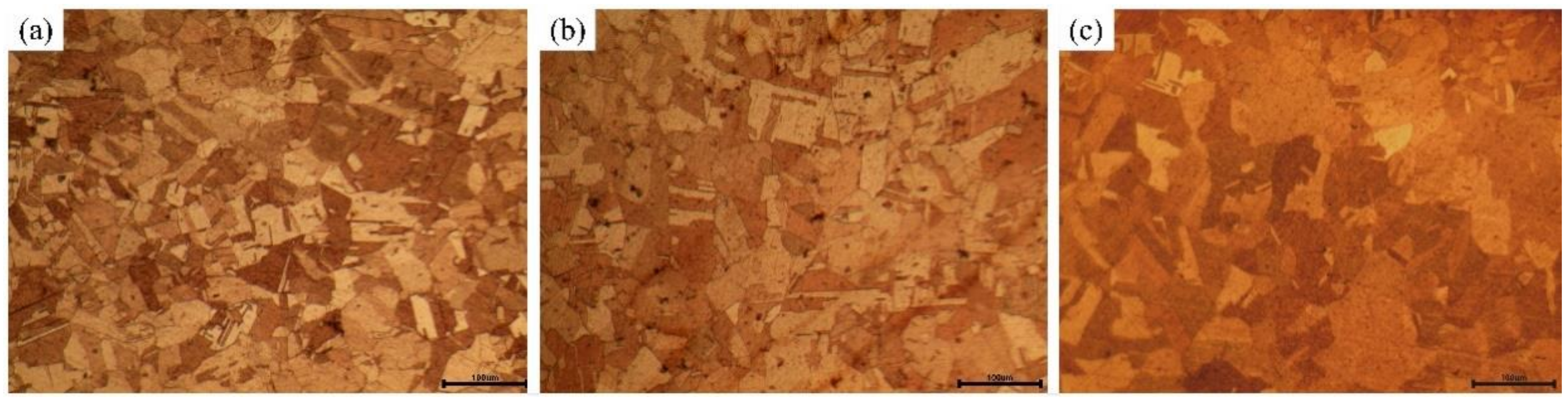
2.1. Workpiece Material

Because commercial OFHC copper is commonly used in electronic components due to its superior electrical conductivity and machinability, it was chosen as the experimental material in this investigation. Different grain sizes were generated by annealing at 450 °C for 2 h, 600 °C for 2 h, and 750 °C for 3 h, respectively, to examine the influence of microstructure on surface integrity, chip formation, and cutting force in the micro-turning process. The workpiece material was annealed in tube vacuum furnaces. The annealing process was continuously supplied with high purity nitrogen to prevent the workpiece from being oxidized and affecting the experimental results.
After cold inlay, a polishing machine was utilized to grind and polish the samples. The samples were polished with 400, 600, 1200, and 2000# water sandpaper in turn. The surface of the sample was ground and polished until the scratches were consistent and uniform each time, and then a further polishing process was performed. Step by step, the samples were polished using alumina polishing solution with particle sizes of 1, 0.5, and 0.3 μm until the surface was smooth and free of visible scratches. For the corrosion solution, we prepared 10 g FeCl3 + 30 mL HCL + 120 mL H2O and used the immersion corrosion technique, using tweezers to keep the sample submerged in the corrosion solution, which underwent corrosion for about 5 s. An optical microscope was used to examine the grain size of the corroded sample. The metallographic microstructure is shown in Figure 1. Nano Measurer software was used to measure and analyze the grain size. The average grain size after heat treatment was 30, 40, and 60 μm, respectively.

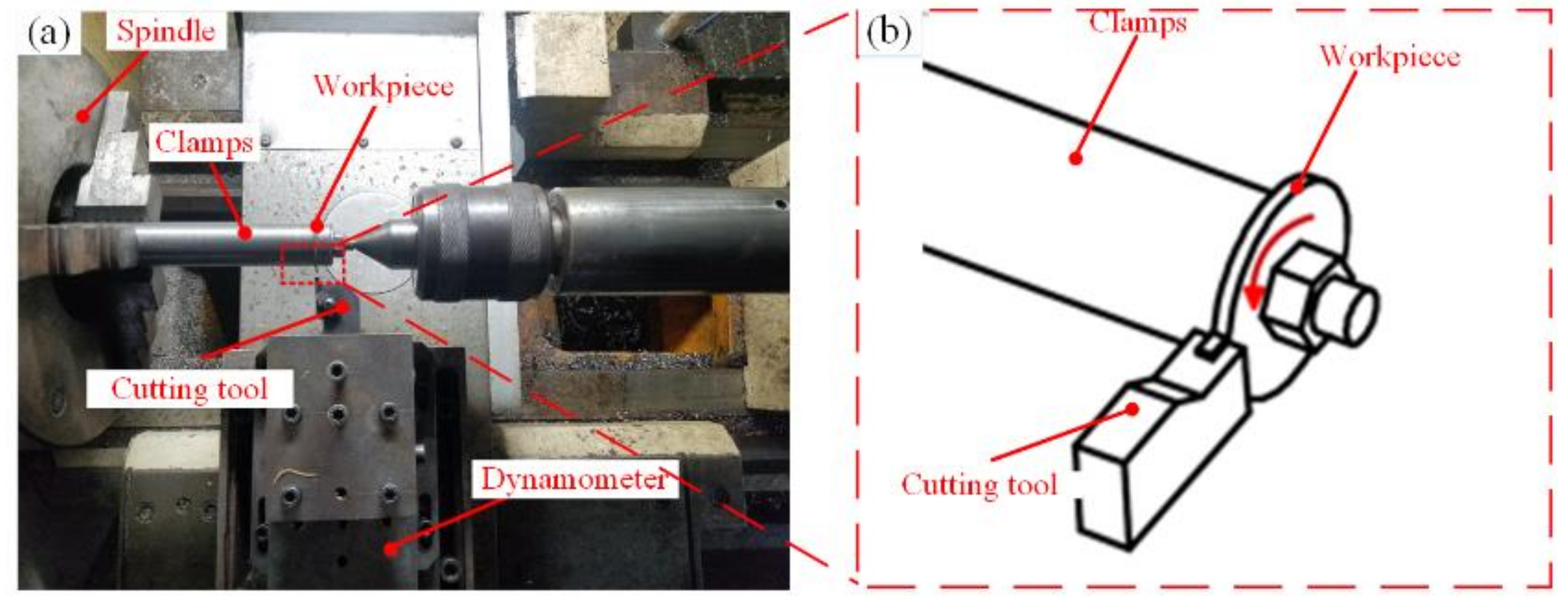
2.2. Experimental Setup

As illustrated in Figure 2a, the orthogonal micro-turning experimental was conducted on a CKD6150H CNC lathe-machining center. The schematic diagram of orthogonal cutting is shown in Figure 2b. Because the feed rate in the micro-cutting process is very small, when the feed rate is less than the minimum chip thickness, the workpiece material does not produce chips, resulting in a severe ploughing and rubbing phenomenon on the surface of the workpiece [15]; when the feed rate is greater than the minimum cutting thickness, the workpiece material will only produce chips. Based on the previous studies’ results [21,22,23,24], a PVD-coated carbide insert (TiAlN) with an edge radius of 25 μm was chosen as a cutting tool in this study, which met the experimental criteria. The rake angle of the cutting tool was 10°, and the relief angle was 11°. The nose radius of the tool was 0.19 mm. The workpiece was disc-shaped with a diameter of 40 mm and a thickness of 1 mm, with a hole in the center. The workpiece was clamped by the fixture and then cut with spindle rotation. The cutting force was measured by Kistler 9257B Dynamometer three-component piezoelectric dynamometers during the experiment, and the lubrication conditions for cutting were dry conditions.
Given the various microstructures of the workpiece after heat treatment (i.e., different grain sizes), feed rates were smaller than the grain size, equal to the grain size, and larger than the grain size, in that order. The cutting speed was 50 m/min. The cutting parameters are shown in Table 1. In particular, each set of intermediate feed rates is equal to the grain size. Cutting experiments with different feed rates were carried out on workpieces with the same microstructure to verify the effect of microstructure on the machining characteristics of OFHC copper. Subheadings may be used to split this section. It should provide a short and summary of the experimental data, their interpretation, and possible experimental inferences.
After the experiment, scanning electron microscopy was used to observe the free surface of chips. The surface roughness was measured by using laser confocal microscopy to investigate the relationship between microstructure and surface integrity.

3. Analysis and Discussion Results

3.1. Machined Surface Integrity

After the experiment, the roughness of the machined surface was measured at five locations on the workpieces in order to avoid accidental errors in the measurement. The topography of the machined surface is shown in Figure 3. Figure 3 clearly shows the path of the turning tool on the surface of the workpiece. The toolpath on the machined surfaces of workpieces with a grain size of 60 μm was more prominent than the other two grain sizes. According to previous studies [5,24], the material flows to the two sides closest to the cutting edge during the cutting process; softer materials are prone to this flow phenomenon. Wang et al. [25] found that the larger the grain size of the material, the more likely it is that plastic flow will occur, and plastic flow increases surface roughness. Therefore, the most pronounced tool paths are found on machined surfaces of workpieces with a grain size of 60 μm.
Ra is based on the line profile method for roughness assessment. Ra is defined as the arithmetic mean deviation of the contour of the distance between points on the surface contour of the object, and the datum line and is mainly used to characterize one-dimensional profiles. Sa is based on the area profile method for roughness assessment. Sa is defined as the distance from the point on the surface profile of an object to the reference plane, which represents the arithmetic mean deviation of the area shape. Sa is mainly used to characterize two-dimensional profiles. It is more suitable when assessing surface roughness in the microscopic field. Therefore, Sa was used to characterize the roughness of machined surfaces in this study; the surface roughness values are shown in Figure 4. The Sa of the finished surface was shown to be the smallest when the feed rate was equal to the grain size for workpieces with the same grain sizes. When the feed rate was smaller than the grain size during the process of micro-turning, the cutting largely occurred inside the grains, the grains were over-twisted and ripped, and the surface roughness was severe. When the feed rate was equal to the grain size, the cutting mostly occurred at the grain boundaries, the grain was stripped from its position, and the surface roughness was slight; when the feed rate was larger than the grain size, the cutting situation was the same as when the feed rate was smaller than the grain size: the cutting occurred inside the grain. The results of laser confocal microscopy also showed that the machined surface was smoother, and there were fewer tool paths on the surface when the feed rate was equal to the grain size.

3.2. Cutting Forces

To avoid chance errors, each group of cutting tests was repeated three times and the cutting forces were collected for the cutting process. The cutting forces Fp (radial force, perpendicular to the machined surface) and Fc (tangential force, parallel to the machined surface) for each group of cutting tests are measured by Kistler 9257B Dynamometer, which collects the force signals during the cutting process in real time and converts them into cutting force curves. The cutting force curves reflect the cutting forces created by the tool from the moment it touches the workpiece to the time it leaves the surface. The experimental cutting force curves were smoothed, and the study utilized the average of each group of cutting forces. The results are shown in Figure 5.
As clearly shown in Figure 5, the feed rate has an important influence on the cutting force of the same microstructure workpiece. Cutting forces increased in a linear relationship with feed rates. This implies that changes in macro-feed rates have a higher impact on cutting forces than changes in grain sizes. From Figure 5d,e, it can be seen that when the feed rate was 30 μm, the cutting force Fc of the workpiece with a grain size of 30 μm was less than that of the workpiece with a grain size of 40 μm. When the feed rate was 30 μm/rev, the turning tool cut the workpiece with a grain size of 30 μm, and the cutting path mostly passed through the grain boundary. However, the workpiece with a grain size of 40 μm was cut by the tool, and the cutting path mostly passed through the inside grain. Cutting inside the grain caused significant dislocation plugging, which in turn produced a large cutting force. The same phenomenon could be seen when the feed rate was 40 μm/rev.

3.3. Chip Formation

The chip morphology in micro-turning processes varies depending on the workpiece material and cutting settings. Due to its good ductility, OFHC copper is commonly processed to produce continuous ribbons of chips. Free surfaces of continuous ribbon chips commonly generate a lamellar pattern, which can be seen with a scanning electron microscope. The schematic diagram of the workpiece chip pattern is shown in Figure 6.
The microscopic morphology of the free surface of chips is shown in Figure 7. The morphology of the lamellar pattern on the free surface is influenced by grain size and cutting settings, as can be observed. On the same chip, such lamellar folds were beautifully placed and about the same width, yet the chips were significantly different. The average width of the free surface lamellar structure was calculated by taking a line of the same length in the direction perpendicular to the lamellar structure at the same scale and determining the number of lamellar patterns on the line; the average width of the lamellar structure results are shown in Figure 8. As can be seen from Figure 8, when the grain sizes are 30 and 40 μm, the width of the lamellar patterns of chips whose feed rates were smaller than the grain size was about 1.5 times wider than when the feed rates were equal to the grain size, and the width of the lamellar patterns of chips whose feed rates were greater than the grain size was 2 times wider than when the feed rates were equal to the grain size.
When the feed rates are equivalent to the grain size, the breadth of the lamellar structures on the free surface is minimized, as seen in Figure 8. Figure 9a shows the microstructure of the chip and Figure 9b shows the microstructure of the machined workpiece. As shown in Figure 9a, the extrusion of the tool and the workpiece causes the original microstructure of the material to change and even form nanocrystals that could not be observed by corrosion during the cutting process. In Figure 9b, the microstructure of the machined workpiece was divided into two parts: region I and region II. Region II is far from the machined surface and is less affected by the machining, and the microstructure does not change much. Region I is close to the machined surface and is more affected by the machining, and the microstructure changes obviously. The microstructure of region I is the same as the microstructure of the chip in Figure 9a. Therefore, it is difficult to draw conclusions through metallographic observations. However, the experimental phenomenon can be indirectly explained by the findings of previous studies [5,26]: The continuous shear slip of the chip tends to alter the grain borders because the ability of grain boundaries to resist deformation is larger than the ability of the grain interior to resist deformation. When the feed rate is equal to the grain size, most of the micro-turning process occurs at the grain boundary and the distance of shear slip is small, so the width of the lamellar structure is small. When the feed is greater or less than the grain size, most micro-turning occurs inside the grain, the distance of the tool passing inside the grain is large, and the distance of cutting shear slip increases; therefore, the width of the lamellar structure is small.

4. Conclusions

In this paper, micro-turning experiments were performed on three different microstructures of OFHC copper to investigate the effects of micro-turning on cutting forces, surface integrity, and chip morphology for the same microstructure at feed rates smaller than, greater than, and equal to the grain size. The following are the key conclusions of this paper:
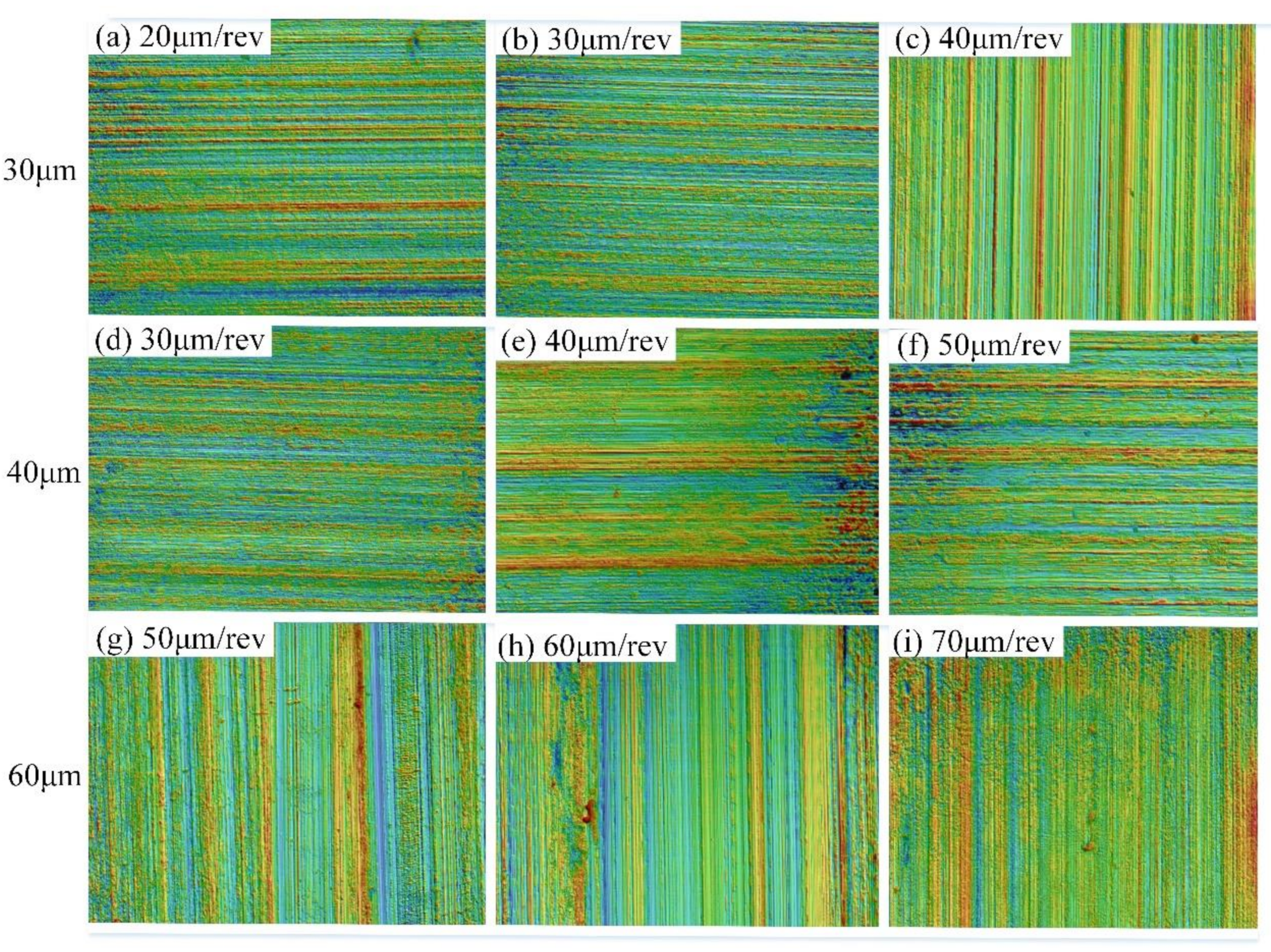
  • The toolpath on the machined surfaces of workpieces with a grain size of 60 μm were more prominent than the other two grain sizes. An explanation for this phenomenon is that material flows to the two sides closest to the cutting edge in the cutting process. The softer the material, the more prone it is to this flow phenomenon, and the workpiece with a grain size of 60 m is the softest. When the feed rate is equal to the grain size for the same grain size workpiece, the Sa of the surface completed is the smallest.
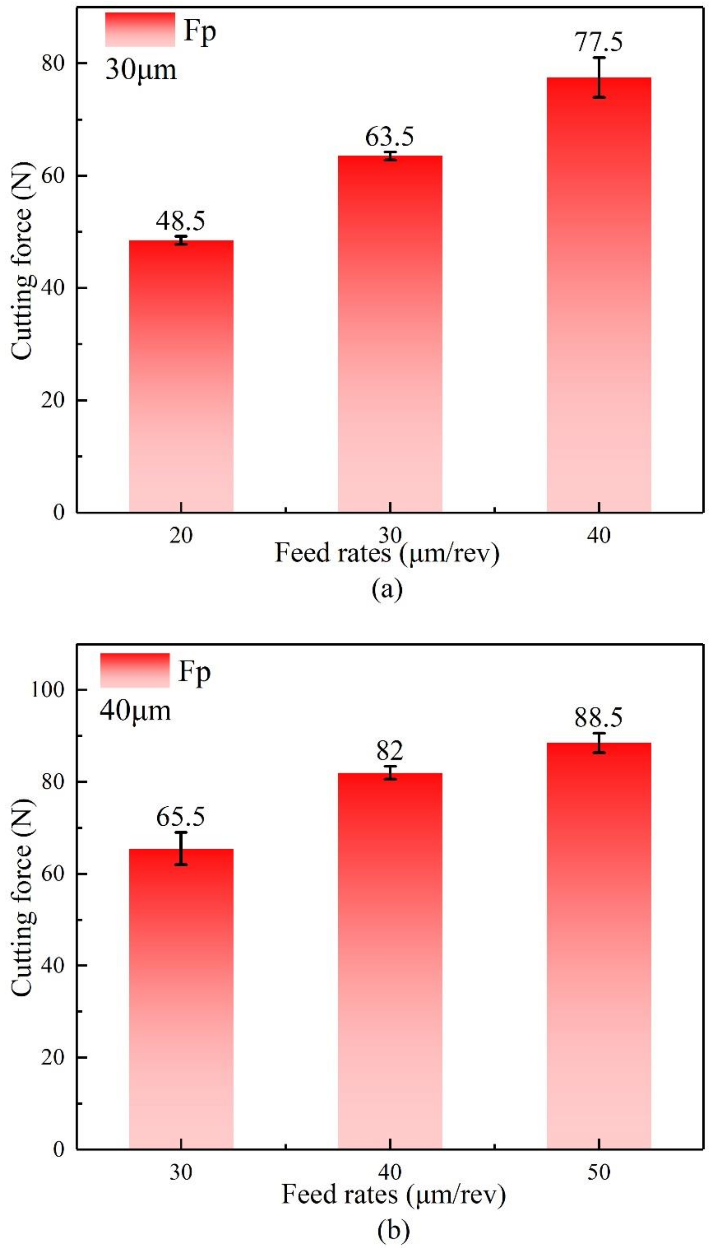
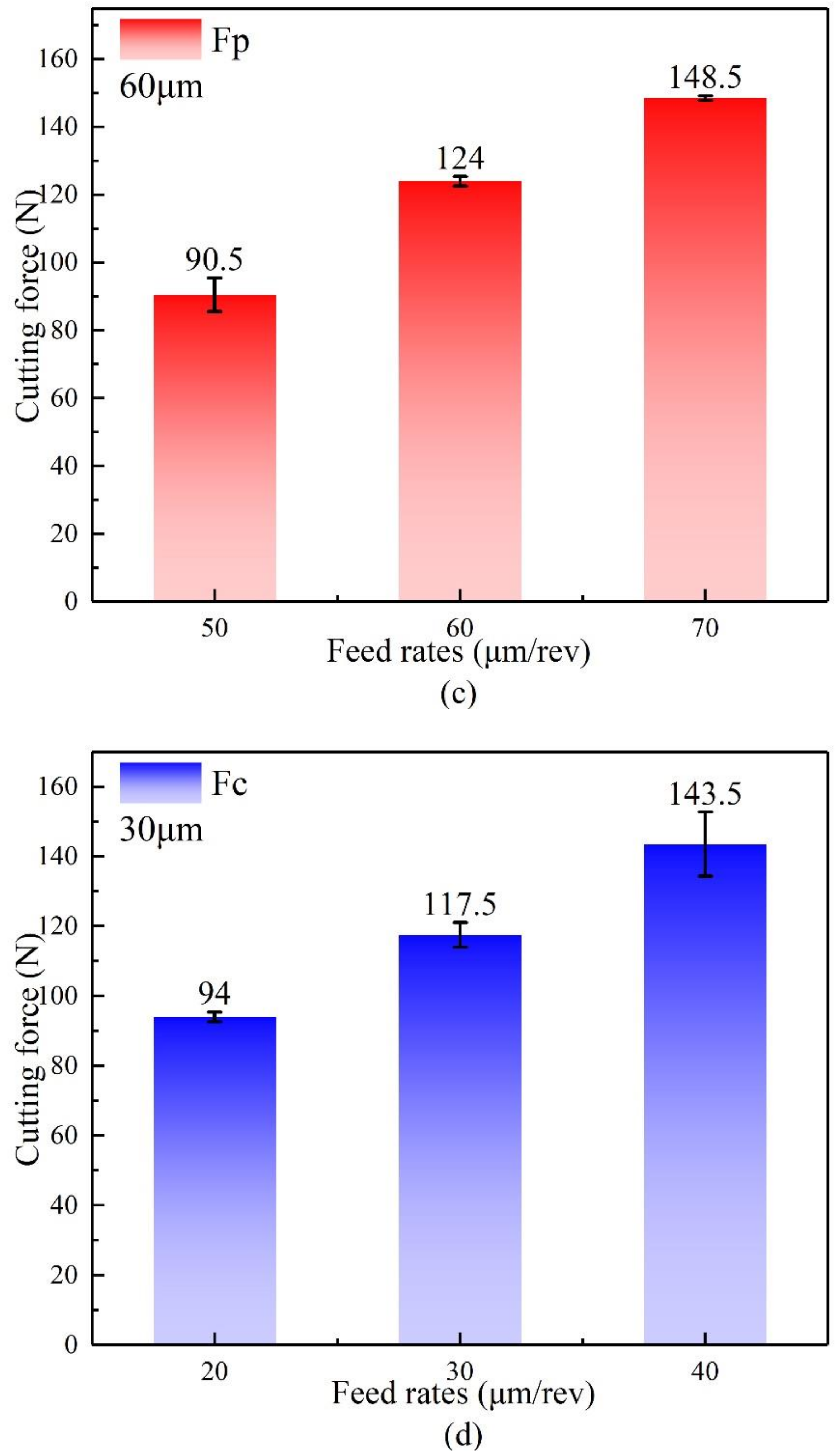
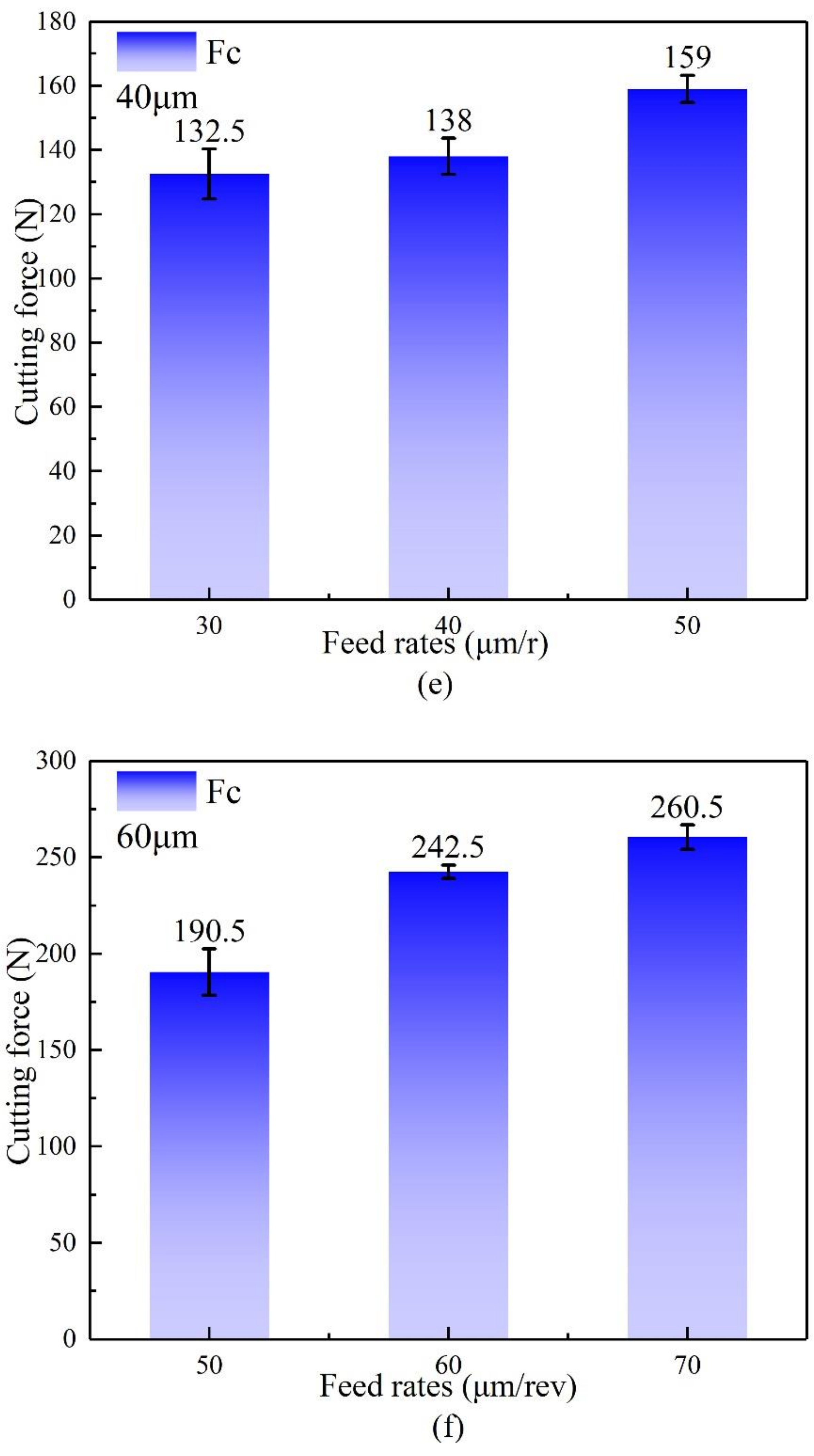
  • The cutting forces increased with increasing feed rates. This indicates that the change in feed rates during the cutting process has a higher influence on the cutting force than the location of the microstructure when the cutting process takes place. When the feed rate was 30 μm, the cutting force Fc of the workpiece with a grain size of 30 μm (cutting happened largely at the grain boundaries) was less than that of the workpiece with a grain size of 40 μm (cutting mostly occurred inside the grain). The reason for this is that cutting inside the grain induced a lot of dislocation plugs, which resulted in a lot of cutting force. Similar behavior may be observed when the feed rate is set to 40 μm/rev.
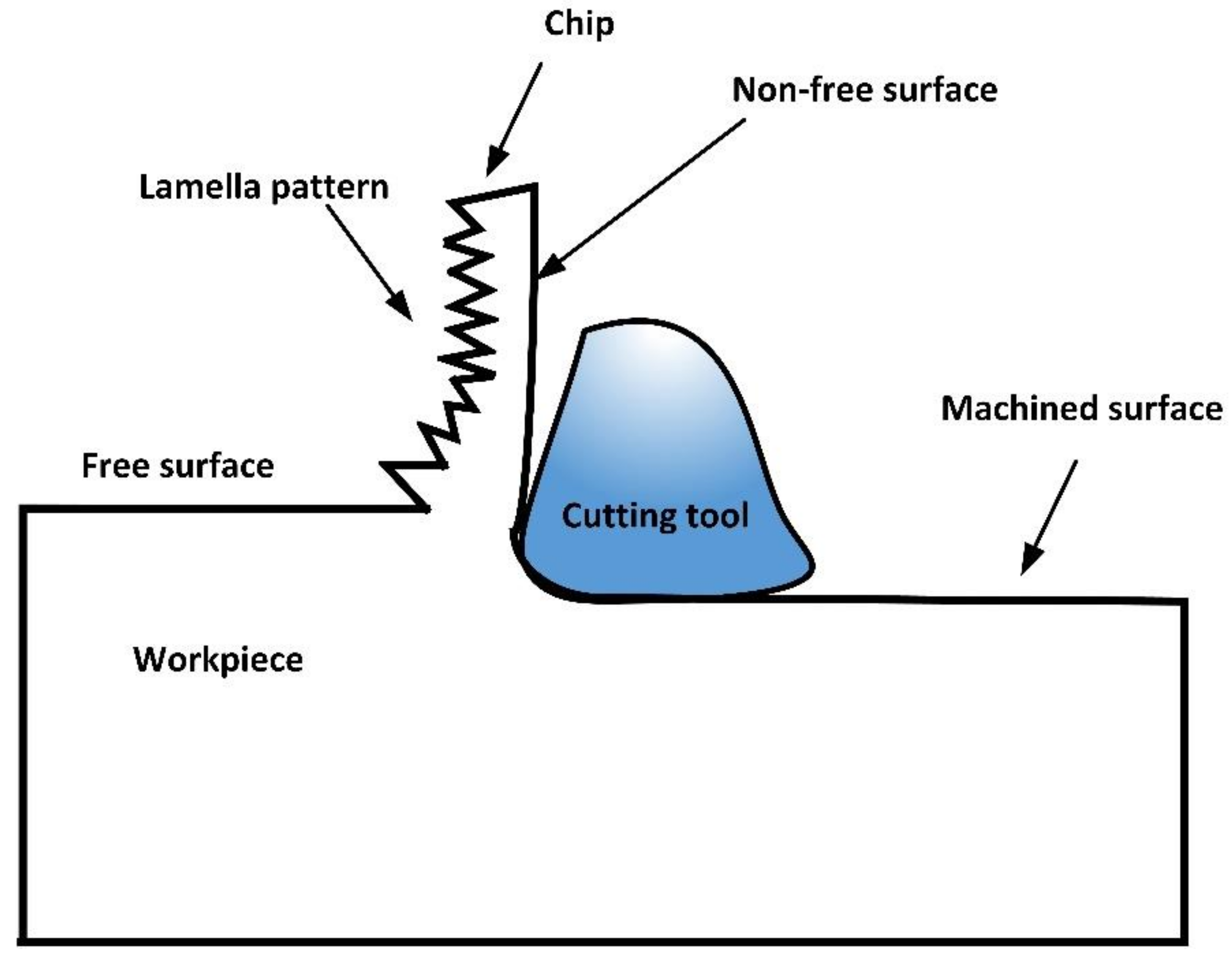
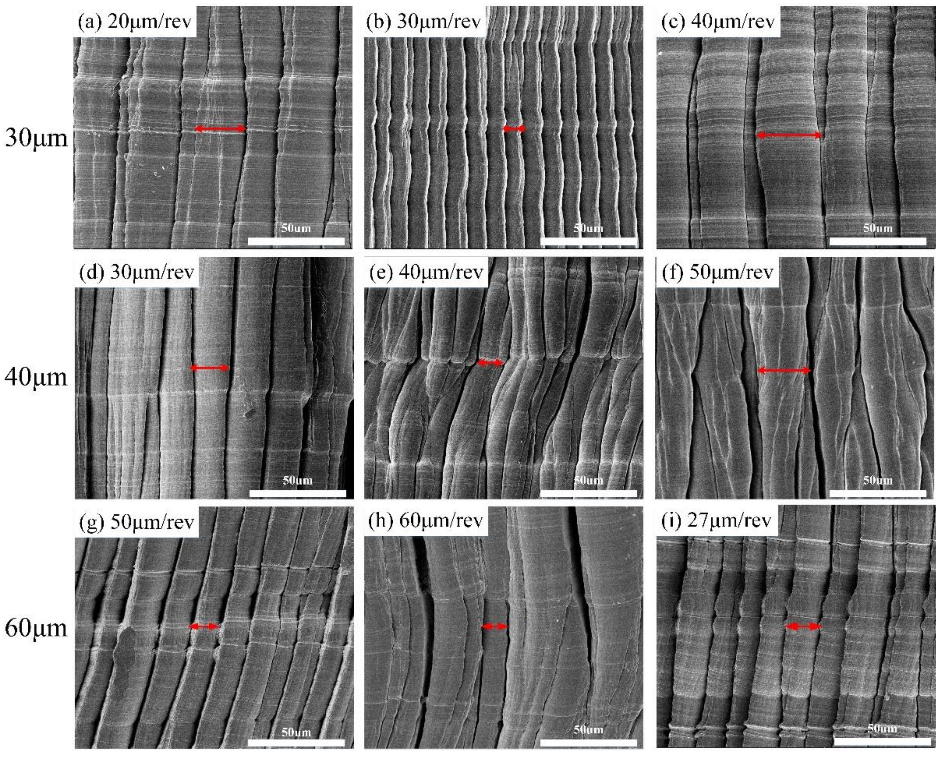
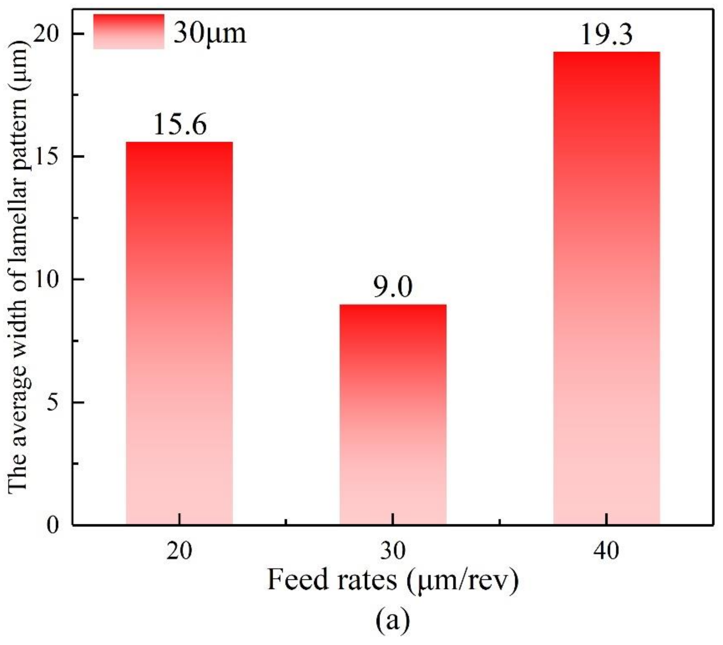
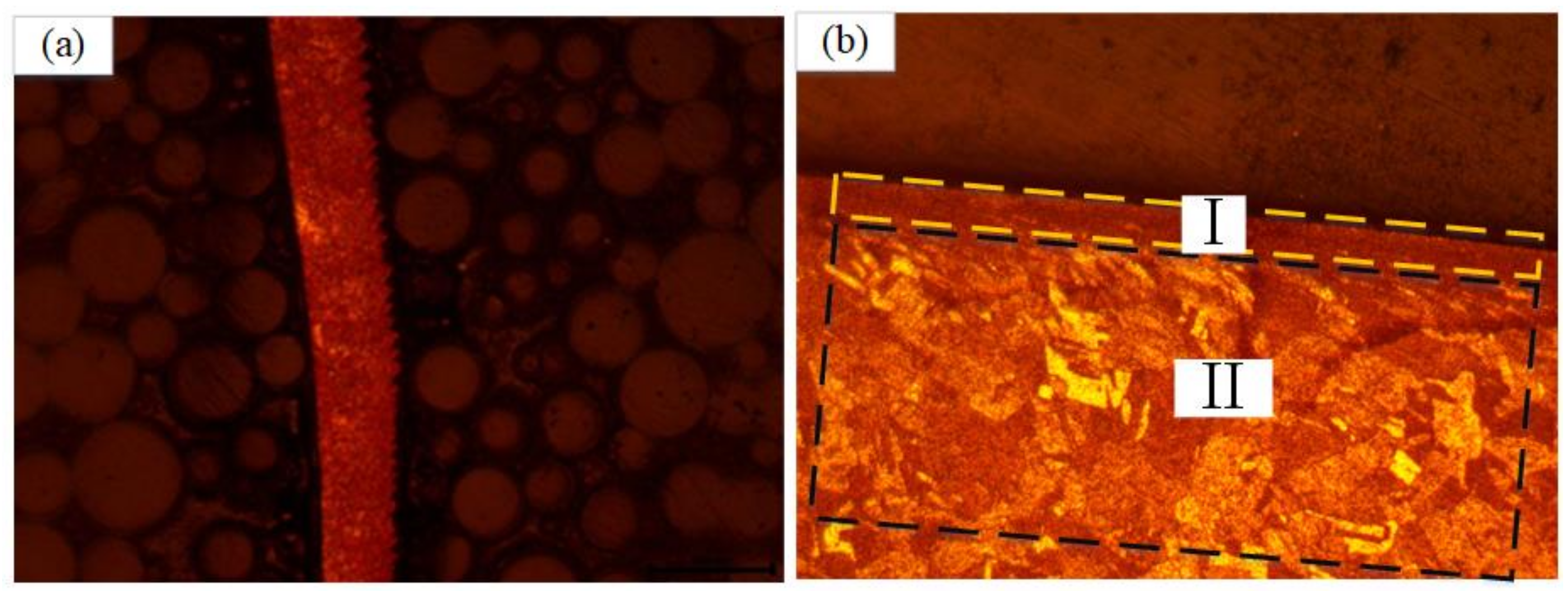
  • On the free surface, there were lamellar patterns that were nicely ordered and almost the same width on the same chip. The breadth of the lamellar patterns on the free surface was minimum when the feed rates were equal to the grain sizes. When the grain sizes were 30 μm and 40 μm, the width of the lamellar patterns of chips whose feed rates were smaller than the grain size was about 1.5 times wider than when the feed rates were equal to the grain size, and the width of the lamellar patterns of chips whose feed rates were greater than the grain size was about 2 times wider than when the feed rates were equal to the grain size.

Author Contributions

Methodology, J.-L.W.; investigation, C.-Z.J. and X.L.; data curation, Y.-F.L. and L.H. All authors have read and agreed to the published version of the manuscript.

Funding

The authors gratefully acknowledge funding supported by the Young Scholars Program of Shandong University, Undergraduate Education Teaching Reform and Research Programs of Shandong University (2021Y220), and Shandong Provincial Natural Science Foundation (ZR2019BEE062).

Institutional Review Board Statement

Not applicable.

Informed Consent Statement

Not applicable.

Data Availability Statement

Data is contained within the article.

Conflicts of Interest

The authors declare no conflict of interest.

References

  1. Jing, C.; Wang, J.; Zhang, C.; Sun, Y.; Shi, Z. Influence of size effect on the dynamic mechanical properties of OFHC copper at micro-/meso-scales. Int. J. Adv. Manuf. Technol. 2022, 1–15. [Google Scholar] [CrossRef]
  2. Sun, X.; Liu, S.; Zhang, X.; Tao, Y.; Boczkaj, G.; Yoon, J.Y.; Xuan, X. Recent advances in hydrodynamic cavitation-based pretreatments of lignocellulosic biomass for valorization. Bioresour. Technol. 2021, 345, 126251. [Google Scholar] [CrossRef] [PubMed]
  3. Xuan, X.; Wang, M.; Zhang, M.; Kaneti, Y.V.; Xu, X.; Sun, X.; Yamauchi, Y. Nanoarchitectonics of low-dimensional metal-organic frameworks toward photo/electrochemical CO2 reduction reactions. J. CO2 Util. 2022, 57, 101883. [Google Scholar] [CrossRef]
  4. Aslantas, K.; Danish, M.; Hasçelik, A.; Mia, M.; Gupta, M.; Ginta, T.; Ijaz, H. Investigations on surface roughness and tool wear characteristics in micro-turning of Ti-6Al-4V alloy. Materials 2020, 13, 2998. [Google Scholar] [CrossRef]
  5. Yu, J.; Wang, G.; Rong, Y. Experimental study on the surface integrity and chip formation in the micro-cutting process. Procedia Manuf. 2015, 1, 655–662. [Google Scholar] [CrossRef] [Green Version]
  6. Zhang, C.; Chen, S.; Wang, J.; Shi, Z.; Du, L. Reproducible Flexible SERS Substrates Inspired by Bionic Micro-Nano Hierarchical Structures of Rose Petals. Adv. Mater. Interfaces 2022, 2102468. [Google Scholar] [CrossRef]
  7. Li, Q.; Wu, Q.; Liu, J.; He, J.; Liu, S. Topology optimization of vibrating structures with frequency band constraints. Struct. Multidiscip. Optim. 2021, 63, 1203–1218. [Google Scholar] [CrossRef]
  8. Bissacco, G.; Hansen, H.N.; Chiffre, L.D. Size Effects on Surface Generation in Micro Milling of Hardened Tool Steel. CIRP Ann. 2006, 55, 593–596. [Google Scholar] [CrossRef] [Green Version]
  9. Zhang, C.; Chen, S.; Jiang, Z.; Shi, Z.; Wang, J.; Du, L. Highly sensitive and reproducible SERS substrates based on ordered micropyramid array and silver nanoparticles. ACS Appl. Mater. Interfaces 2021, 13, 29222–29229. [Google Scholar] [CrossRef]
  10. Mian, A.J.; Driver, N.; Mativenga, P.T. A comparative study of material phase effects on micro-machinability of multiphase materials. Int. J. Adv. Manuf. Technol. 2010, 50, 163–174. [Google Scholar] [CrossRef]
  11. Li, Q.; Sigmund, O.; Jensen, J.S.; Aage, N. Reduced-order methods for dynamic problems in topology optimization: A comparative study. Comput. Methods Appl. Mech. Eng. 2021, 387, 114149. [Google Scholar] [CrossRef]
  12. Kumar, S.P.L. Measurement and uncertainty analysis of surface roughness and material removal rate in micro turning operation and process parameters optimization. Measurement 2019, 140, 538–547. [Google Scholar] [CrossRef]
  13. Zhang, S.J.; To, S.; Cheung, C.F.; Zhu, Y.H. Microstructural changes of Zn–Al alloy influencing micro-topographical surface in micro-cutting. Int. J. Adv. Manuf. Technol. 2014, 72, 9–15. [Google Scholar] [CrossRef]
  14. Vipindas, K.; Anand, K.N.; Mathew, J. Effect of cutting edge radius on micro end milling: Force analysis, surface roughness, and chip formation. Int. J. Adv. Manuf. Technol. 2018, 97, 711–722. [Google Scholar] [CrossRef]
  15. Wu, X.; Li, L.; He, N.; Yao, C.; Zhao, M. Influence of the cutting edge radius and the material grain size on the cutting force in micro cutting. Precis. Eng. 2016, 45, 359–364. [Google Scholar] [CrossRef]
  16. Komatsu, T.; Yoshino, T.; Matsumura, T.; Torizuka, S. Effect of crystal grain size in stainless steel on cutting process in micromilling. Procedia Cirp 2012, 1, 150–155. [Google Scholar] [CrossRef]
  17. Venkatachalam, S.; Fergani, O.; Li, X.; Guo Yang, J.; Chiang, K.N.; Liang, S.Y. Microstructure effects on cutting forces and flow stress in ultra-precision machining of polycrystalline brittle materials. J. Manuf. Sci. Eng. 2015, 137, 021020. [Google Scholar] [CrossRef]
  18. Jiang, L.; Roos, Å.; Liu, P. The influence of austenite grain size and its distribution on chip deformation and tool life during machining of AISI 304L. Metall. Mater. Trans. A 1997, 28, 2415–2422. [Google Scholar] [CrossRef]
  19. Wu, X.; Li, L.; He, N.; Zhao, M.; Zhan, Z. Investigation on the influence of material microstructure on cutting force and bur formation in the micro-cutting of copper. Int. J. Adv. Manuf. Technol. 2015, 79, 321–327. [Google Scholar] [CrossRef]
  20. Popov, K.B.; Dimov, S.S.; Pham, D.T.; Minev, R.M.; Rosochowski, A.; Olejnik, L. Micromilling: Material microstructure effects. Proc. Inst. Mech. Eng. Part B J. Eng. Manuf. 2006, 220, 1807–1813. [Google Scholar] [CrossRef]
  21. Lai, X.; Li, H.; Li, C.; Lin, Z.; Ni, J. Modelling and analysis of micro-scale milling considering size effect, micro cutter edge radius and minimum chip thickness. Int. J. Mach. Tools Manuf. 2008, 48, 1–14. [Google Scholar] [CrossRef]
  22. Sun, X.; Yang, Z.; Wei, X.; Tao, Y.; Boczkaj, G.; Yoon, J.Y.; Xuan, X.; Chen, S. Multi-objective optimization of the cavitation generation unit structure of an advanced rotational hydrodynamic cavitation reactor. Ultrason. Sonochem. 2021, 80, 105771. [Google Scholar] [CrossRef]
  23. Ikawa, N.; Shimada, S.; Tanaka, H. Minimum thickness of cut in micromachining. Nanotechnology 1992, 3, 6. [Google Scholar] [CrossRef]
  24. Yuan, Z.J.; Zhou, M.; Dong, S. Effect of diamond tool sharpness on minimum cutting thickness and cutting surface integrity in ultraprecision machining. J. Mater. Process. Technol. 1996, 62, 327–330. [Google Scholar] [CrossRef]
  25. Wang, J.L.; Fu, M.W.; Shi, S.Q. Influences of size effect and stress condition on ductile fracture behavior in micro-scaled plastic deformation. Mater. Des. 2017, 131, 69–80. [Google Scholar] [CrossRef]
  26. Wang, J.S.; Gong, Y.D.; Abba, G.; Chen, K.; Shi, J.S.; Cai, G.Q. Surface generation analysis in micro end-milling considering the influences of grain. Microsyst. Technol. 2008, 14, 937–942. [Google Scholar] [CrossRef] [Green Version]
Figure 1. Microstructure of annealed OFHC copper. (a) 30 μm, (b) 40 μm, and (c) 60 μm.
Processes 10 00741 g001
Figure 2. (a) Experimental setup, (b) schematic diagram of cutting.
Processes 10 00741 g002
Figure 3. The topography of the machined surface. The grain size of the workpiece is 30 μm: (a) feed rate = 20 μm/rev, (b) feed rate = 30 μm/rev, (c) feed rate = 40 μm/rev; The grain size of the workpiece is 40 μm: (d) feed rate = 30 μm/rev, (e) feed rate = 40 μm/rev, (f) feed rate = 50 μm/rev; The grain size of the workpiece is 60 μm: (g) feed rate = 50 μm/rev, (h) feed rate = 60 μm/rev, (i) feed rate = 70 μm/rev.
Processes 10 00741 g003
Figure 4. The roughness of machined surface at different feed rates. (a) Grain size = 30 μm, (b) Grain size = 40 μm, (c) Grain size = 60 μm.
Processes 10 00741 g004
Figure 5. The cutting forces at different feeding rates. (ac) Cutting forces Fp of Grain size = 30 μm, 40 μm, 60 μm, respectively; (df) Cutting forces Fc of Grain size = 30 μm, 40 μm, 60 μm, respectively.
Processes 10 00741 g005aProcesses 10 00741 g005bProcesses 10 00741 g005c
Figure 6. Schematic diagram of workpiece chip pattern.
Processes 10 00741 g006
Figure 7. Micromorphology of free surface of workpiece chips at different feed rates. (ac) Grain size = 30 μm, (df) Grain size = 40 μm, (gi) Grain size = 60 μm.
Processes 10 00741 g007
Figure 8. The average width of the lamellar structure: (a) 30 μm, (b) 40 μm, (c) 60 μm.
Processes 10 00741 g008aProcesses 10 00741 g008b
Figure 9. The microstructure of (a) the chip and (b) the machined workpiece.
Processes 10 00741 g009
Table 1. The parameters of micro-cutting.
Machine ToolCKD6150H Lathe-Machining Center
Cutting speed (m/min)50
Cutting tool PVD-coated carbide insert (TiAlN)
Workpiece materialOFHC copper
Feed rate (μm/rev)20, 30, 40
30, 40, 50
50, 60, 70
Publisher’s Note: MDPI stays neutral with regard to jurisdictional claims in published maps and institutional affiliations.

