1. Introduction
With the growth in the agriculture and aquaculture industry, the demand for transportation pumps has increased. The pumps can be efficient and effective substitutes for transportation. Among various pump categories, jet pumps and screw centrifugal pumps are used in sewage transfer, petroleum, metallurgy, and other industries for transportation [
1,
2]. Therefore, jet pumps and centrifugal pumps are the most viable options to solve the transportation problem of sensitive goods such as vegetables and live fish.
Jet pumps are preferred for transportation because they are simple in design without rotating and reciprocating components, low cost, and have desirable mass transfer [
3,
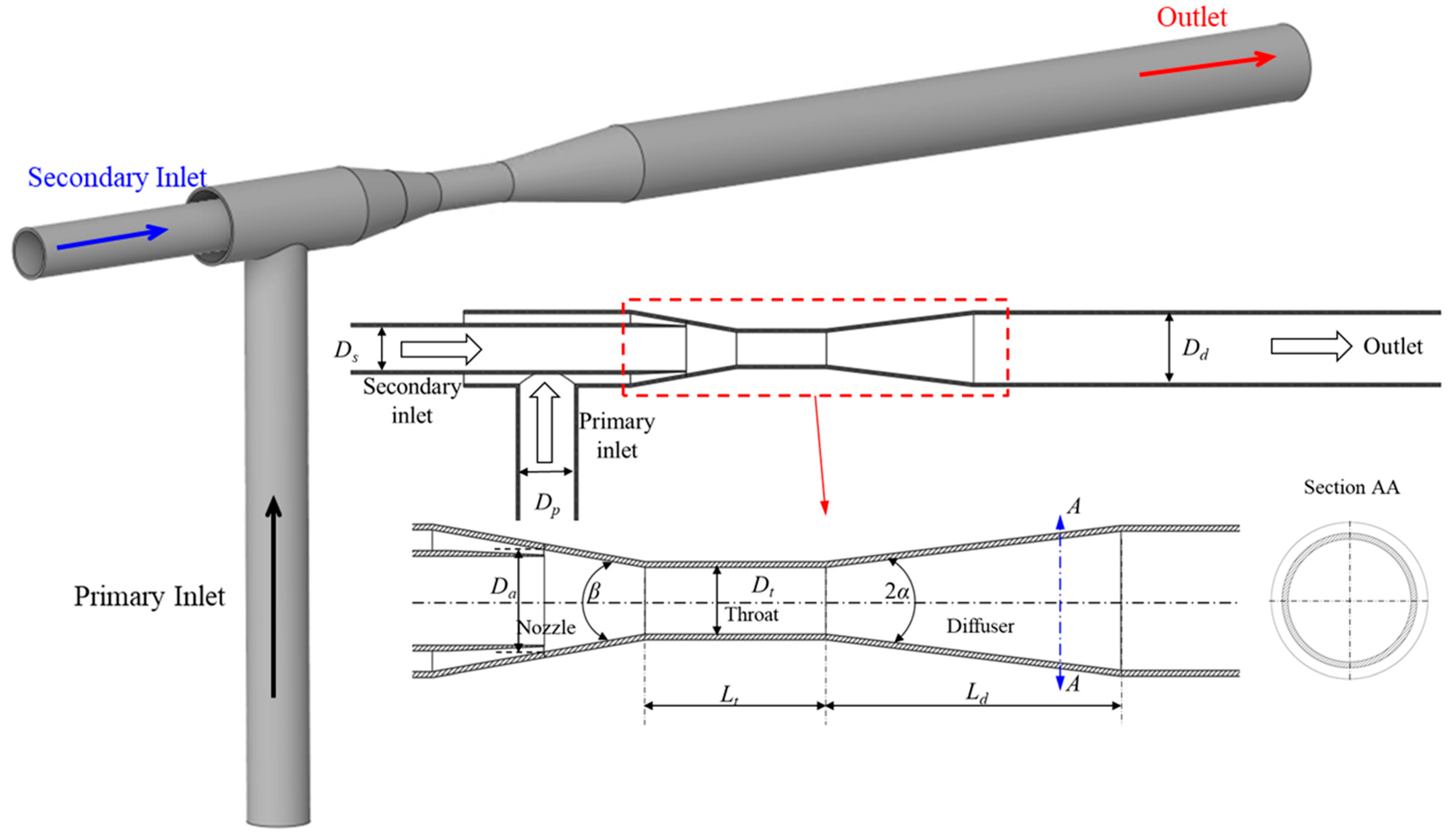
4]. The primary and secondary inlets, nozzle, diffuser, and outlet are the main components of a jet pump. A jet pump converts pressure energy into kinetic energy using a nozzle and diffuser. The high pressurized primary flow passes through the nozzle and increases the fluid velocity, which creates a low-pressure zone in the throat and withdraws secondary fluid. Finally, the high-pressure primary fluid mixes with low-pressure secondary fluid at the throat and diffuses to the outlet via a diffuser [
5]. The drawbacks of the jet pump are friction loss, mixing loss, and the possibility of cavitation. Generally, two types of jet pump are available in the market, central jet pump (CJP) and annular jet pump (AJP) [
6]. The nozzle position distinguishes between CJPs and AJPs. In CJPs, the primary pressurized fluid passes through the central nozzle, whereas in AJPs, the pressurized fluid passes through the annular nozzle. Numerous studies [
7,
8,
9] were conducted on the design and operation of CJPs. Hatzlavramidis [
7] proposed the design methodology to model CJPs. The CJP performance is dependent on the nozzle shape, size, and number [
8]. Zhu et al. [
9] established the computational methodology for the design and engineering practice of CJPs.
Hence, an AJP is selected to improve the suction performance for the transfer of sensitive goods. Shimizu et al. [
10] conducted the experimental analysis on various AJP geometry configurations to evaluate hydraulic and suction performance. Elger et al. [
6] introduced dimensionless parameters to study the recirculation flow in an AJP. AJP performance is directly related to the nozzle shape and size [
11]. Kwon et al. [
12] conducted numerical analysis on an AJP and showed that recirculation mainly occurs under partial flow conditions. Numerical analysis showed that AJPs are more efficient in transportation [
13].
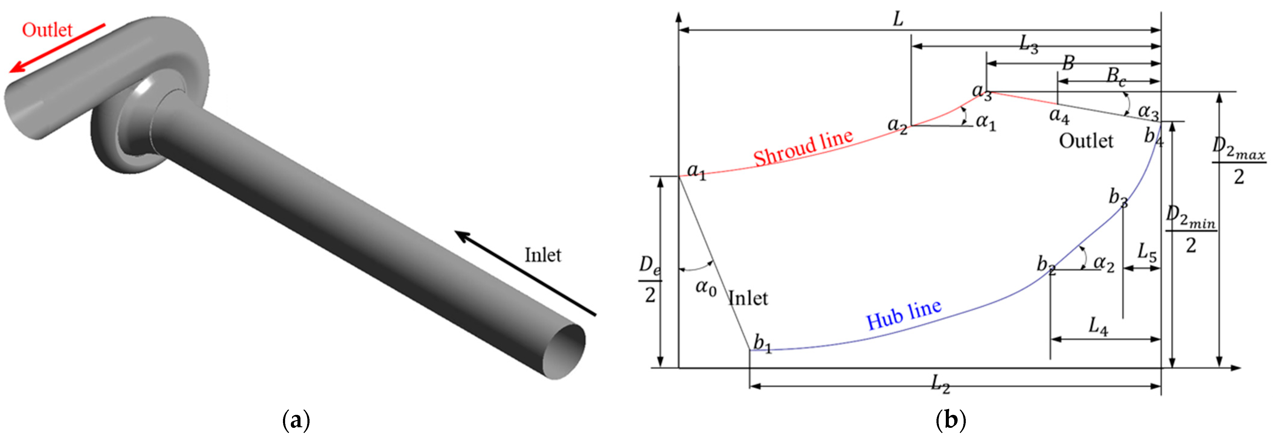
The screw centrifugal pump (SCP) is used for slurries, sewage, and sensitive goods transfer. The SCP has a large and open channel from suction to discharge, which helps to transfer the solid particles without clogging. SCPs have a three-dimensional spiral blade added to the conical hub cone. It is the combination of screw pump and centrifugal pump which provides spiral propeller and centrifugal effects, respectively [
14]. The higher efficiency, no blockage area, a wide range of operation, and better solid handling capability are the advantages of screw centrifugal pumps over traditional slurry pumps [
15]. Few studies were conducted to understand the SCP. The meridional shape parameters of the screw centrifugal pump influence the performance and internal flow [
16]. The axial thrust becomes larger where the impeller radius reaches the tongue of the volute casing [
17]. Cheng et al. [
18] explained the parametric equation for the design of the SCP impeller blade. Guo et al. [
19] showed the design method and internal flow behavior of the SCP.
The cavitation occurrence is the main problem for the proper operation of the AJP and the SCP. Cavitation vapor bubbles occur in the nozzle of the AJP and inlet of the SCP impeller blade when they operate below the saturated vapor pressure. The cavitation reduces the pump efficiency and damages the transported goods. The instability of the re-entrant jet and pressure gradient in the re-entrant jet creates cloud cavitation in the divergence section of the AJP [
20]. Xiao et al. [
21] conducted cavitation analysis in the AJP. Cavitation in the AJP can be caused by increasing the primary jet velocity or decreasing pump outlet pressure [
22]. The cavitation phenomenon in the SCP is like in the centrifugal pump and is caused by reducing the inlet pressure. Backflow vortex cavitation and tip leakage cavitation occur at the impeller inlet of the SCP. Cavitation in the AJP and SCP is dependent on the flow condition. Cavitation causes severe damage to sensitive goods such as fish [
23]. The improvement of pressure distribution will suppress cavitation in the AJP and the SCP.
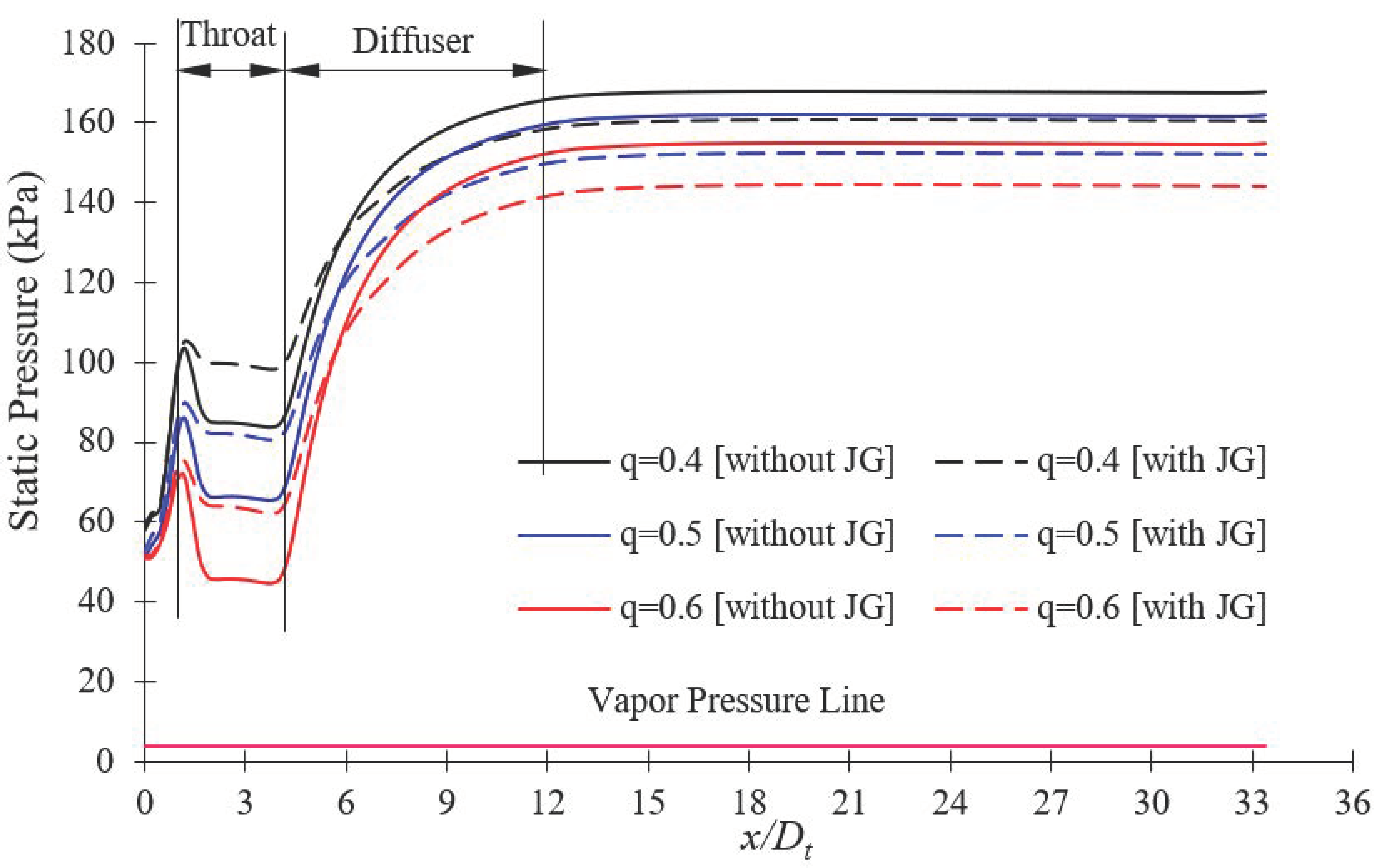
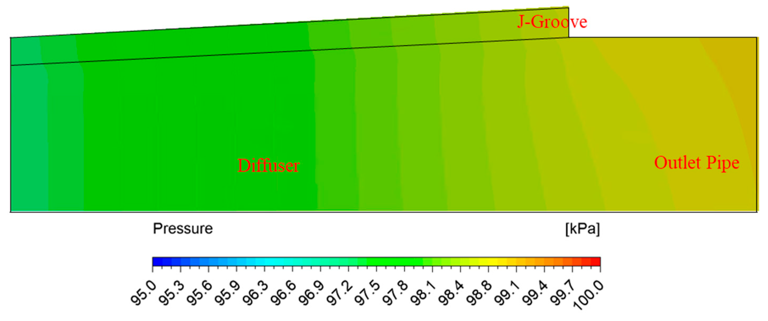
The flow field in the AJP and SCP models are alike as a diffuser without and with an impeller, respectively. The diffuser is a pressure-momentum device that focuses on recovering static pressure at the expense of kinetic energy [
24]. The static pressure recovery coefficient for the diffuser is calculated as
where
is static pressure (Pa),
is dynamic pressure (Pa),
is velocity (m/s),
is the density of fluid (kg/m
3),
is the pressure recovery coefficient, and subscripts 1 and 2 represent the inlet and outlet of the diffuser.
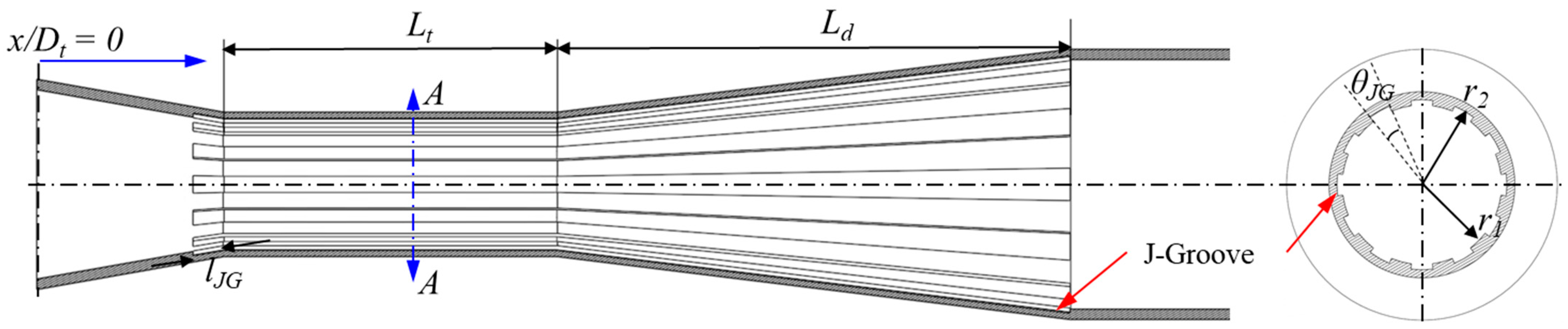
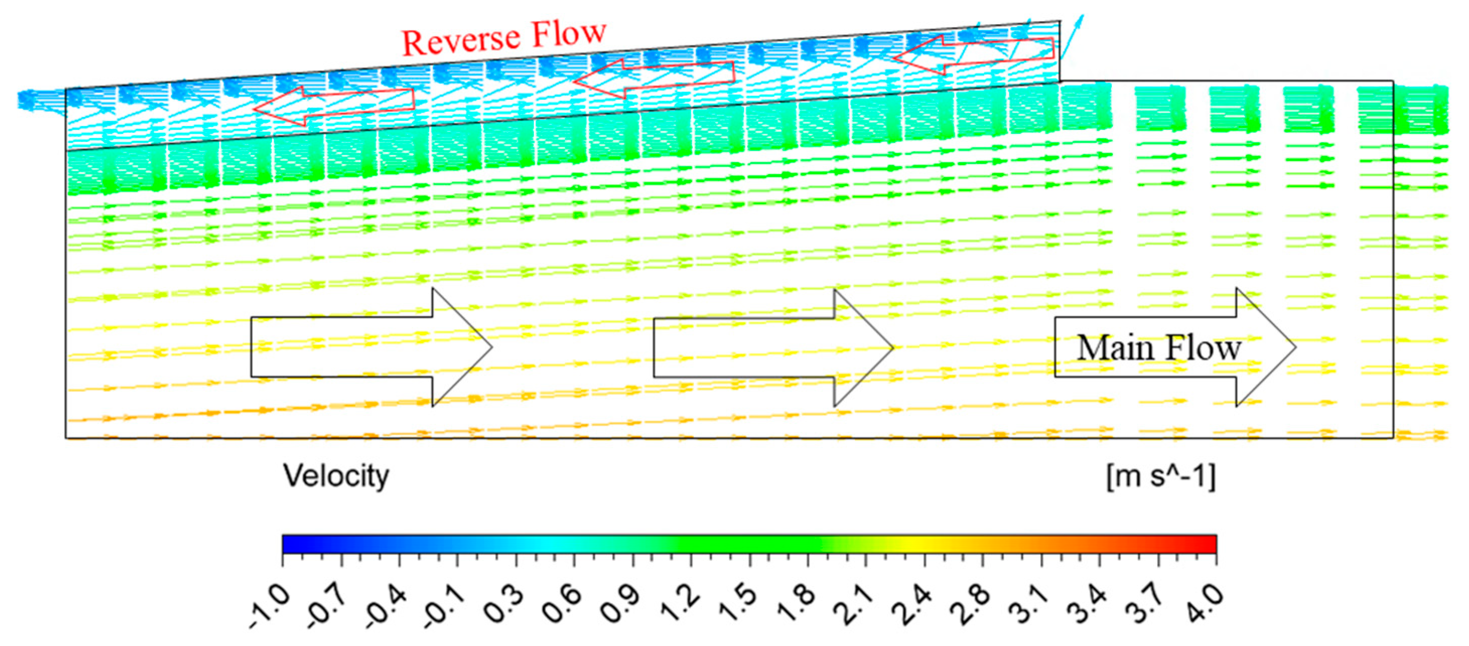
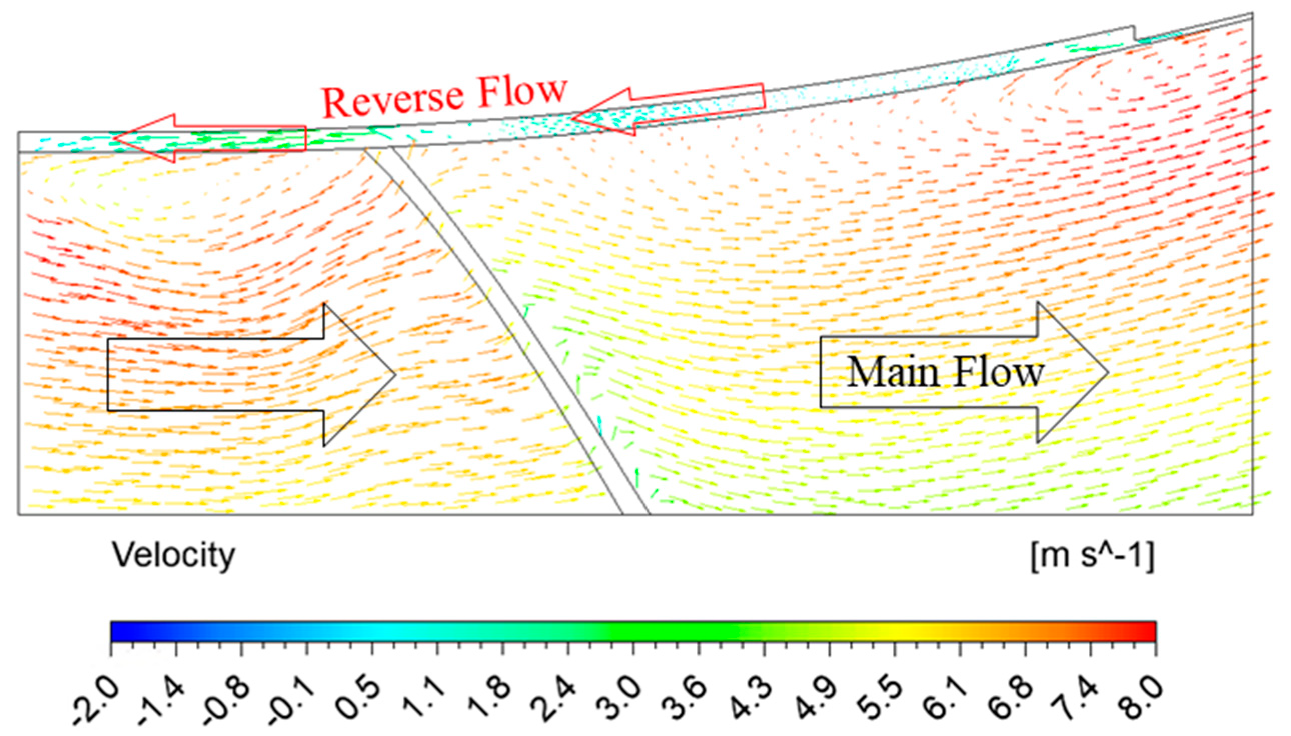
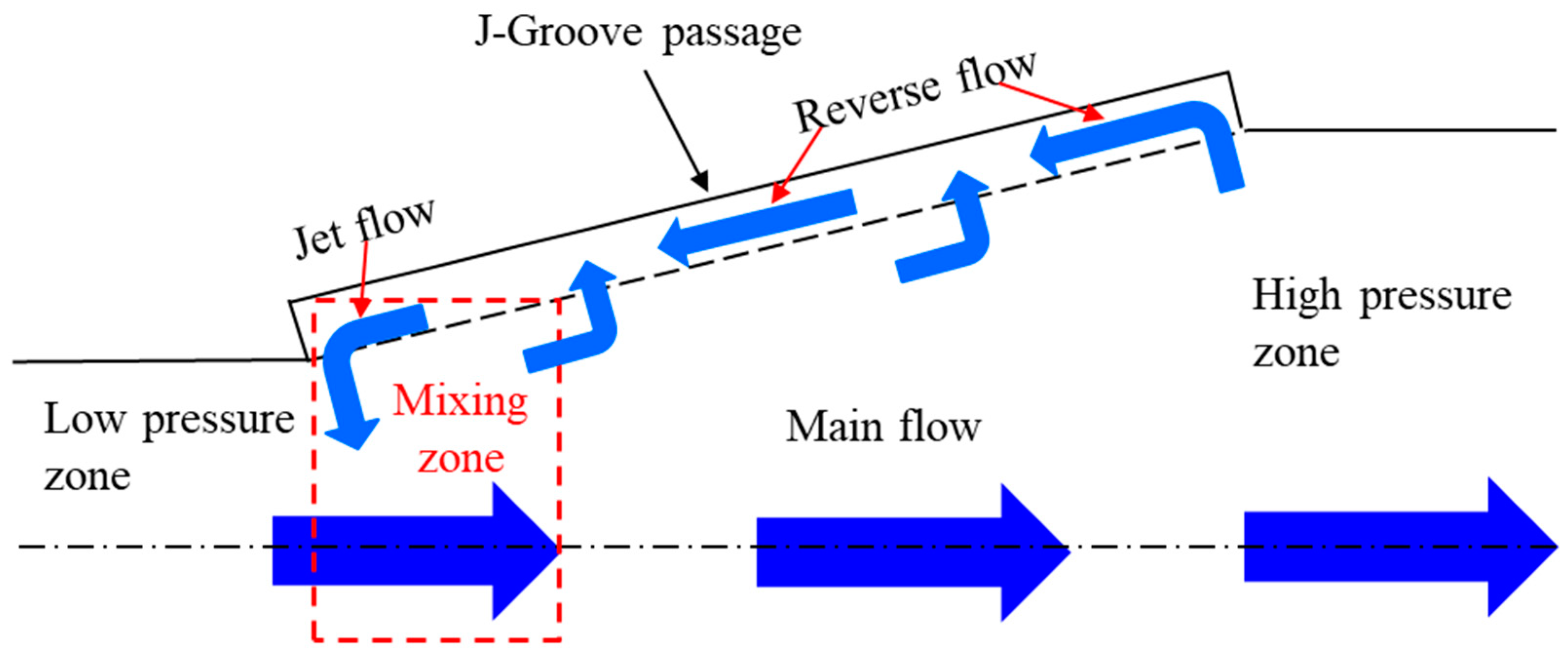
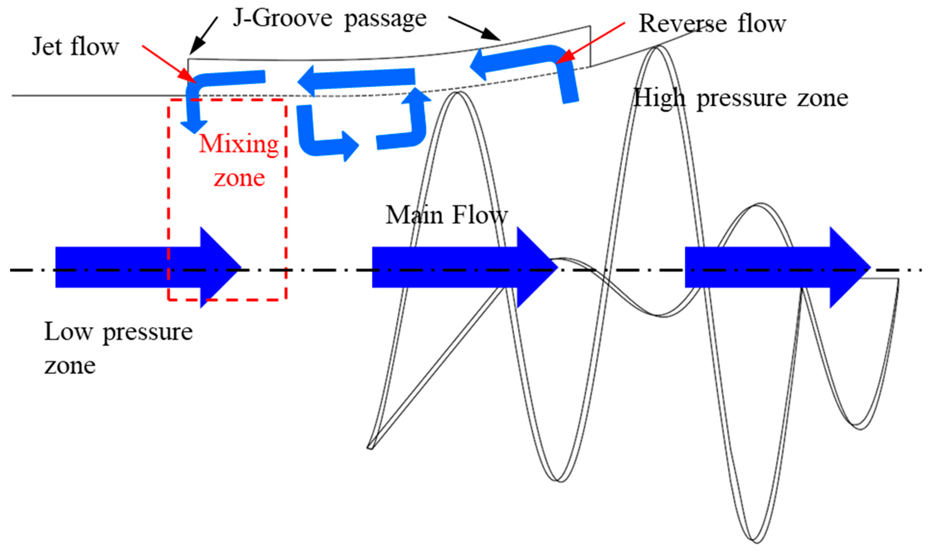
J-Groove is a simple passive approach to suppress cavitation in the diffuser of AJP and the impeller wall of the SCP [
25,
26]. It induces the reverse jet flow and suppresses cavitation in the diffuser wall [
27]. The main design parameters for J-Groove are depth, length, angle, and number [
28], and its depth plays a vital role in the reverse flow rate and suction performance improvement [
29].
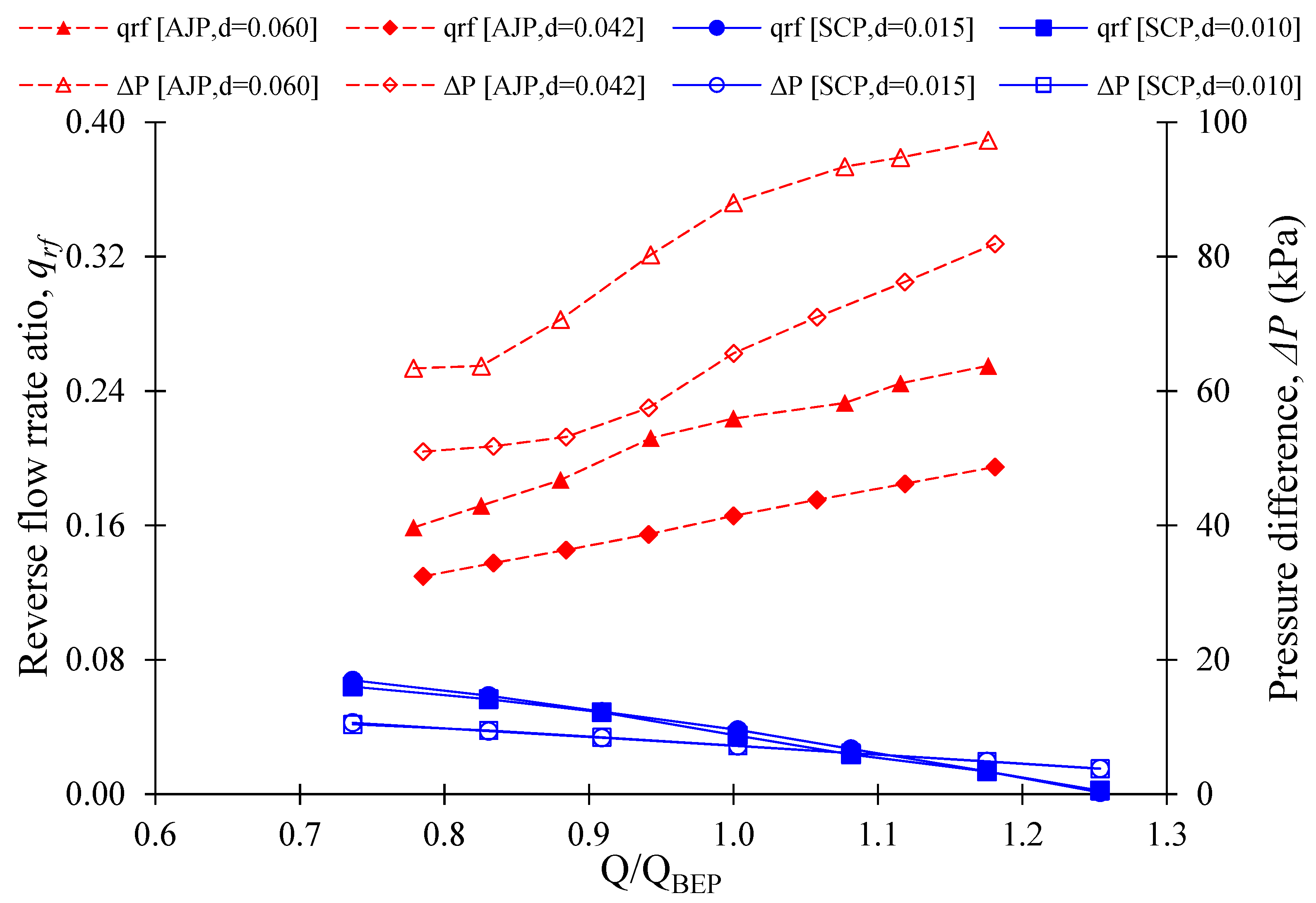
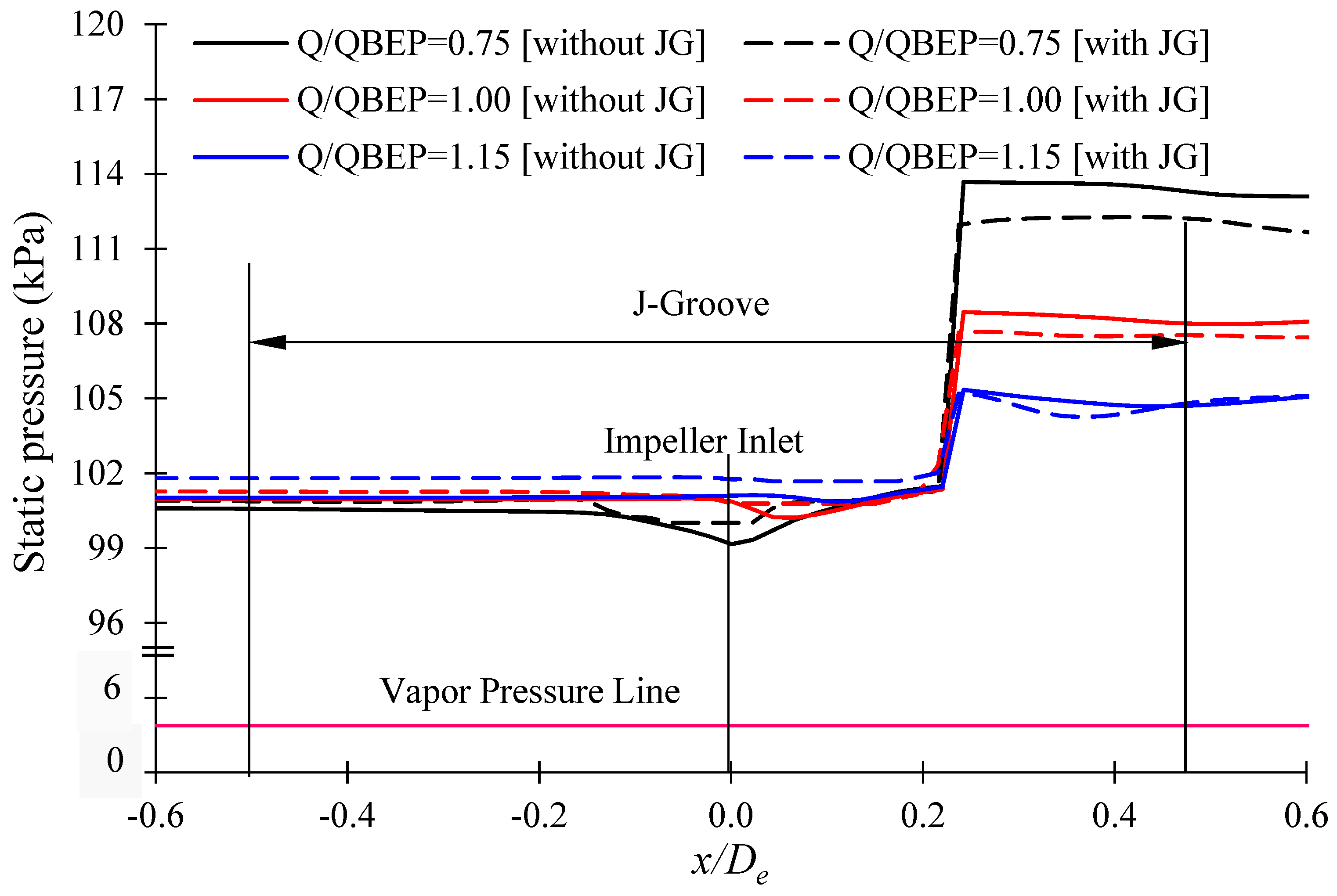
The flow in J-Groove is dependent on the pressure difference. In a diffuser
, it directs the flow in the J-Groove from the outlet to the inlet of the diffuser. Hence, a reverse flow can be observed in the diffuser with J-Groove. This study is focused on the reverse flow rate influence on the hydraulic and suction performance of AJP and SCP models. The study objective is to estimate the reverse flow rate through J-Groove passages in AJP and SCP models.
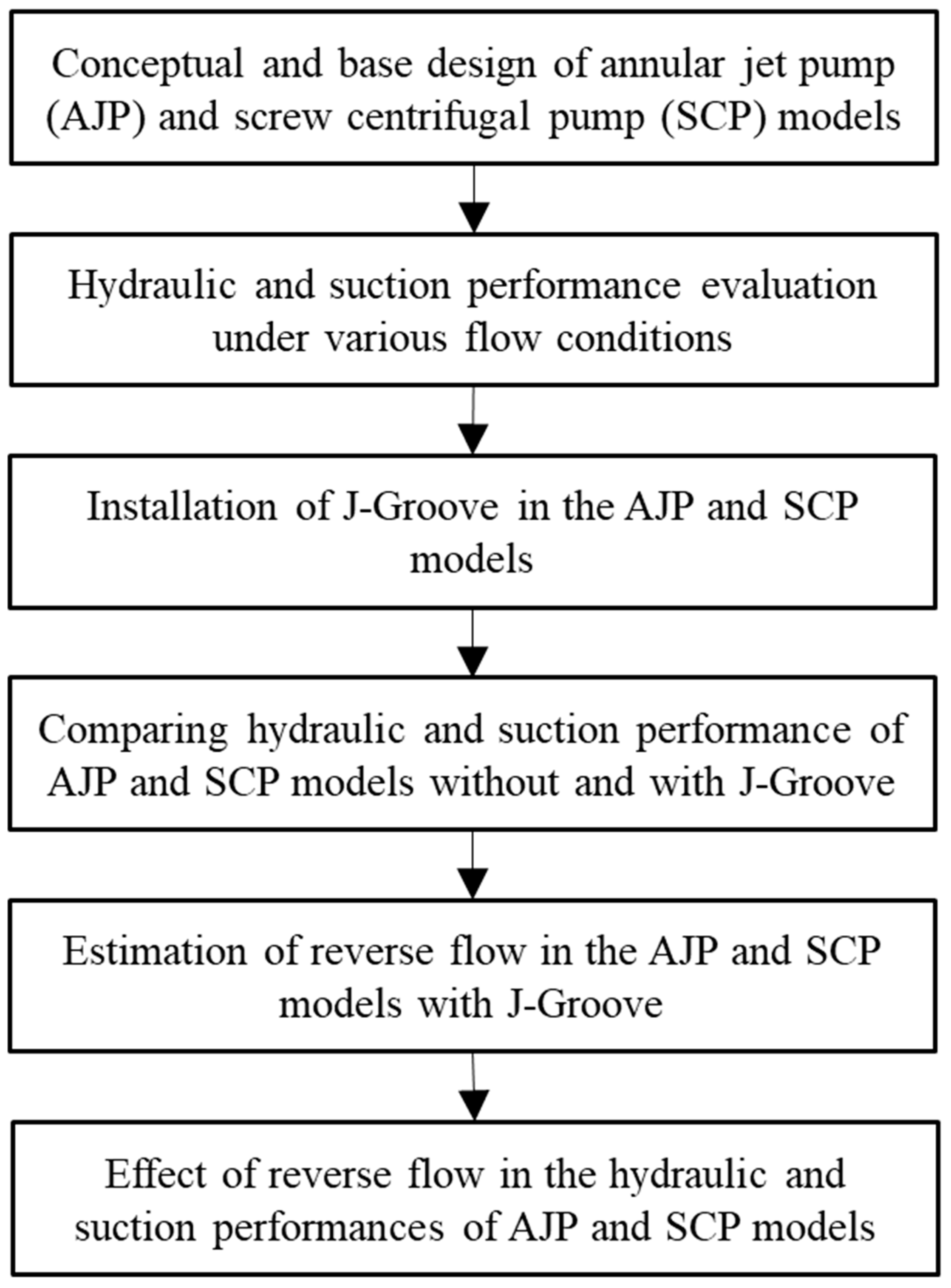
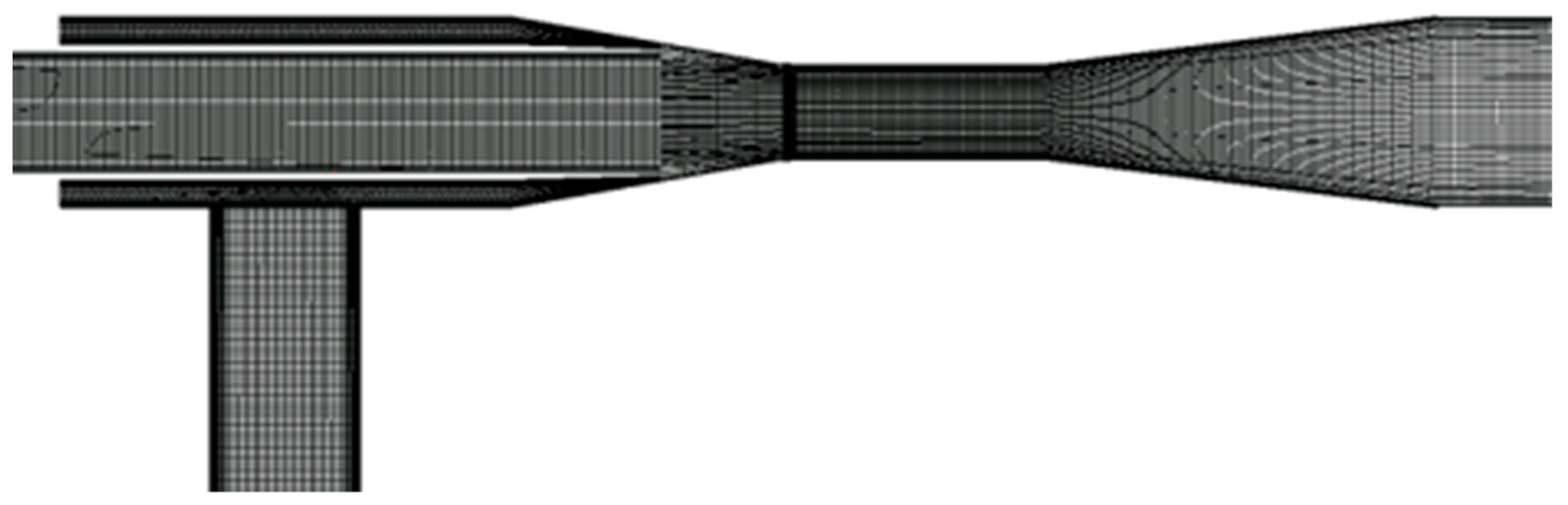
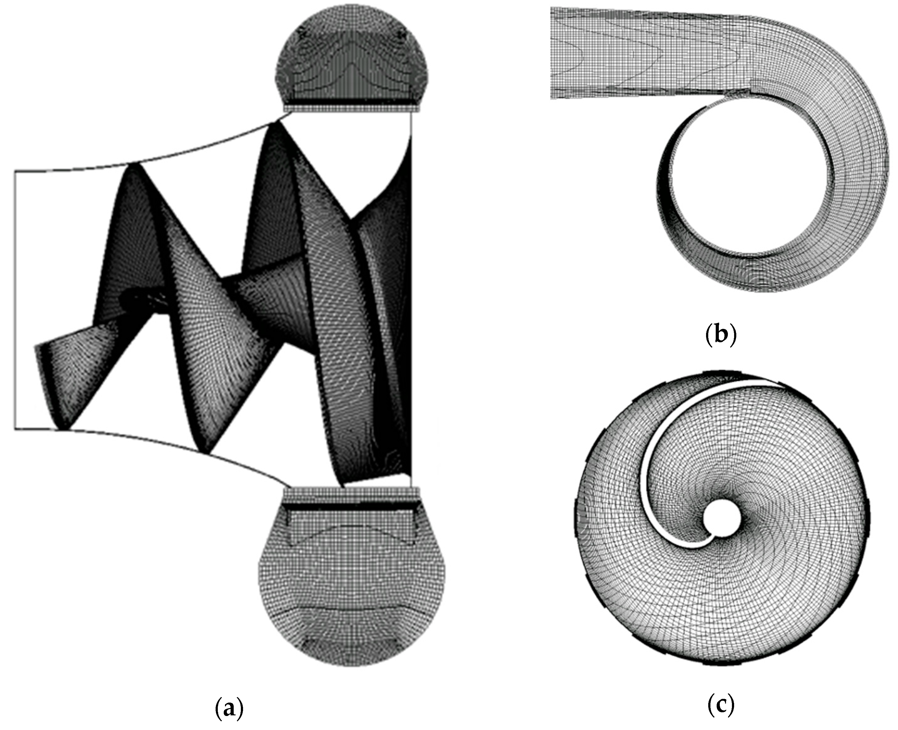
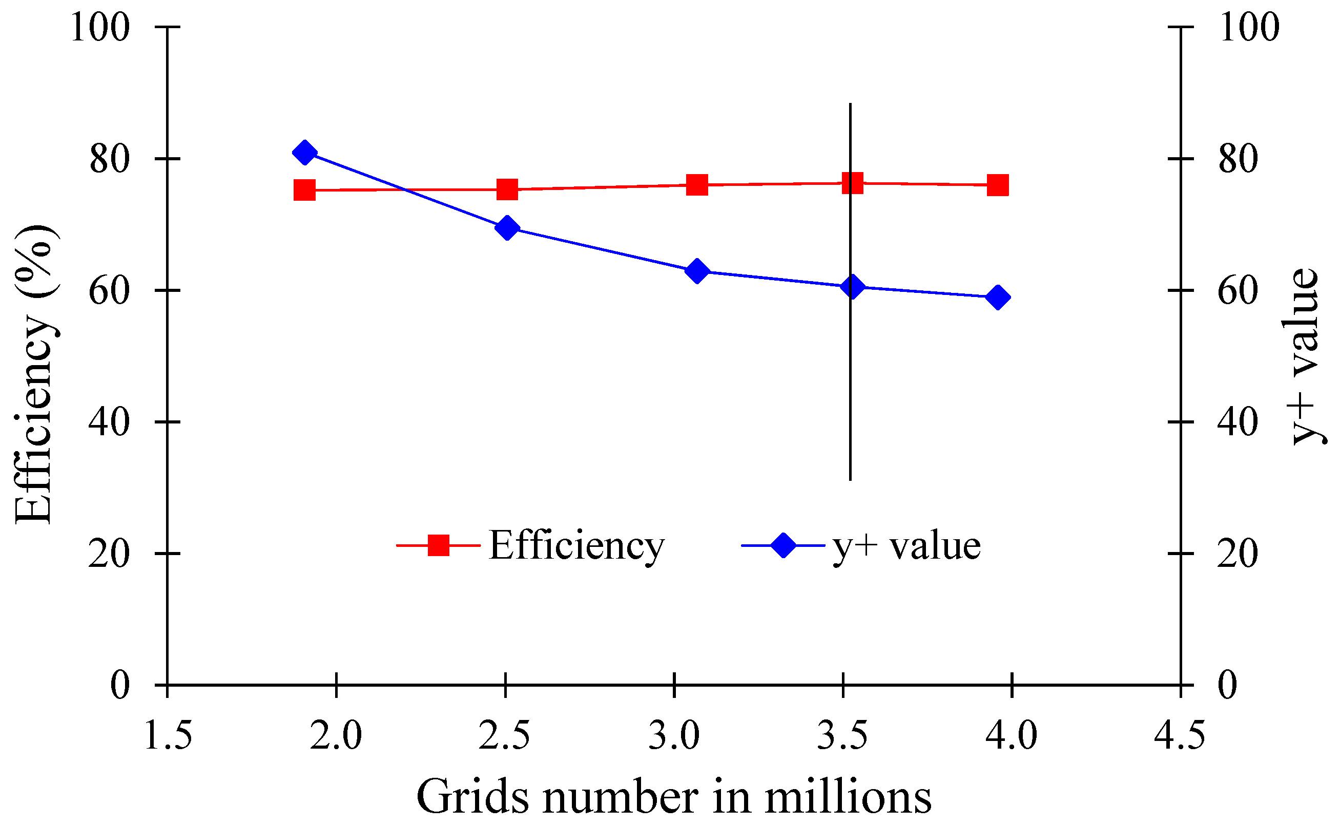
Figure 1 shows a flow chart that evaluates the reverse flow rate in AJP and SCP models.
4. Conclusions
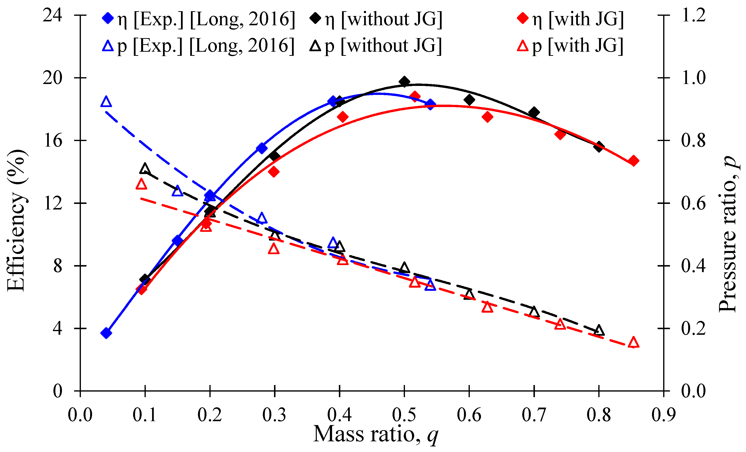
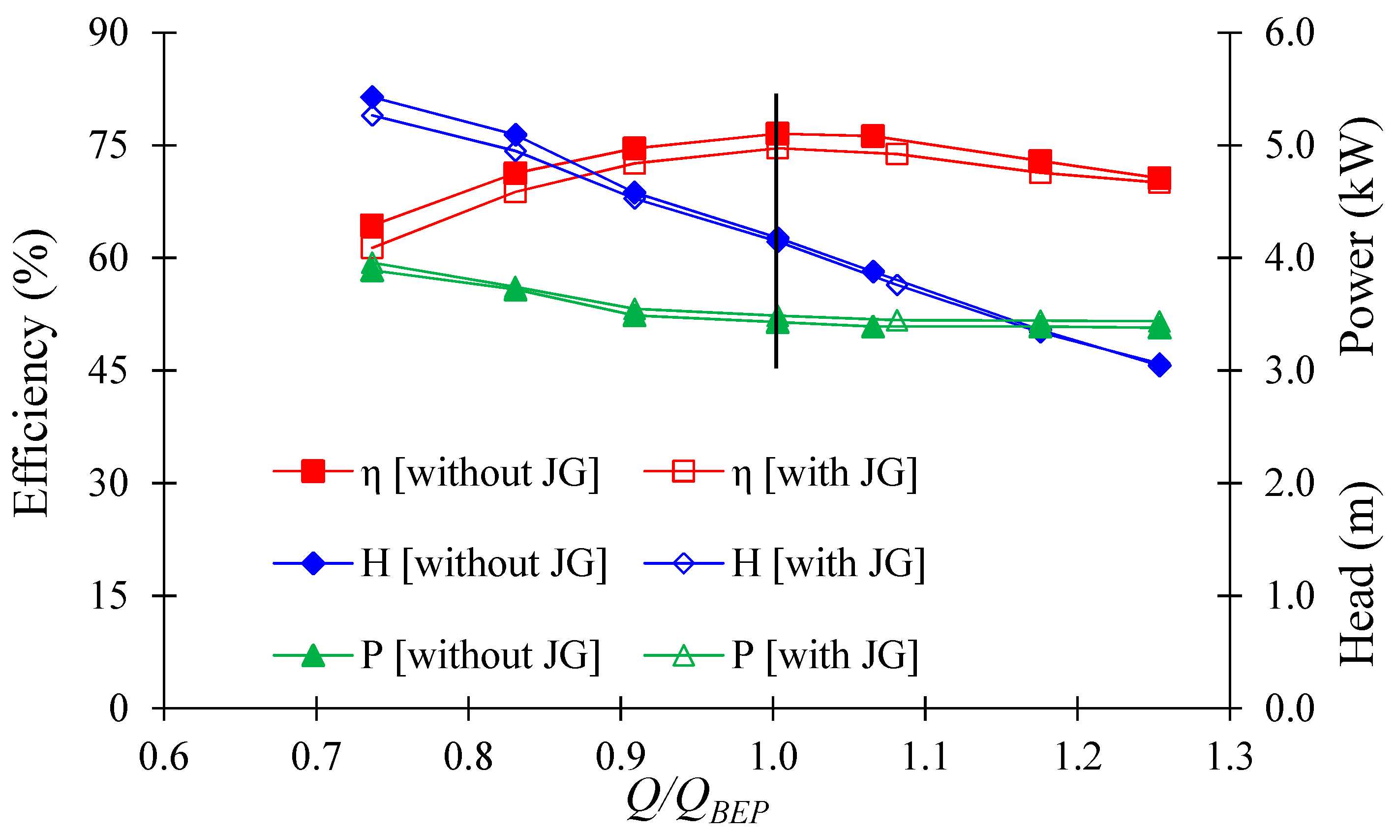
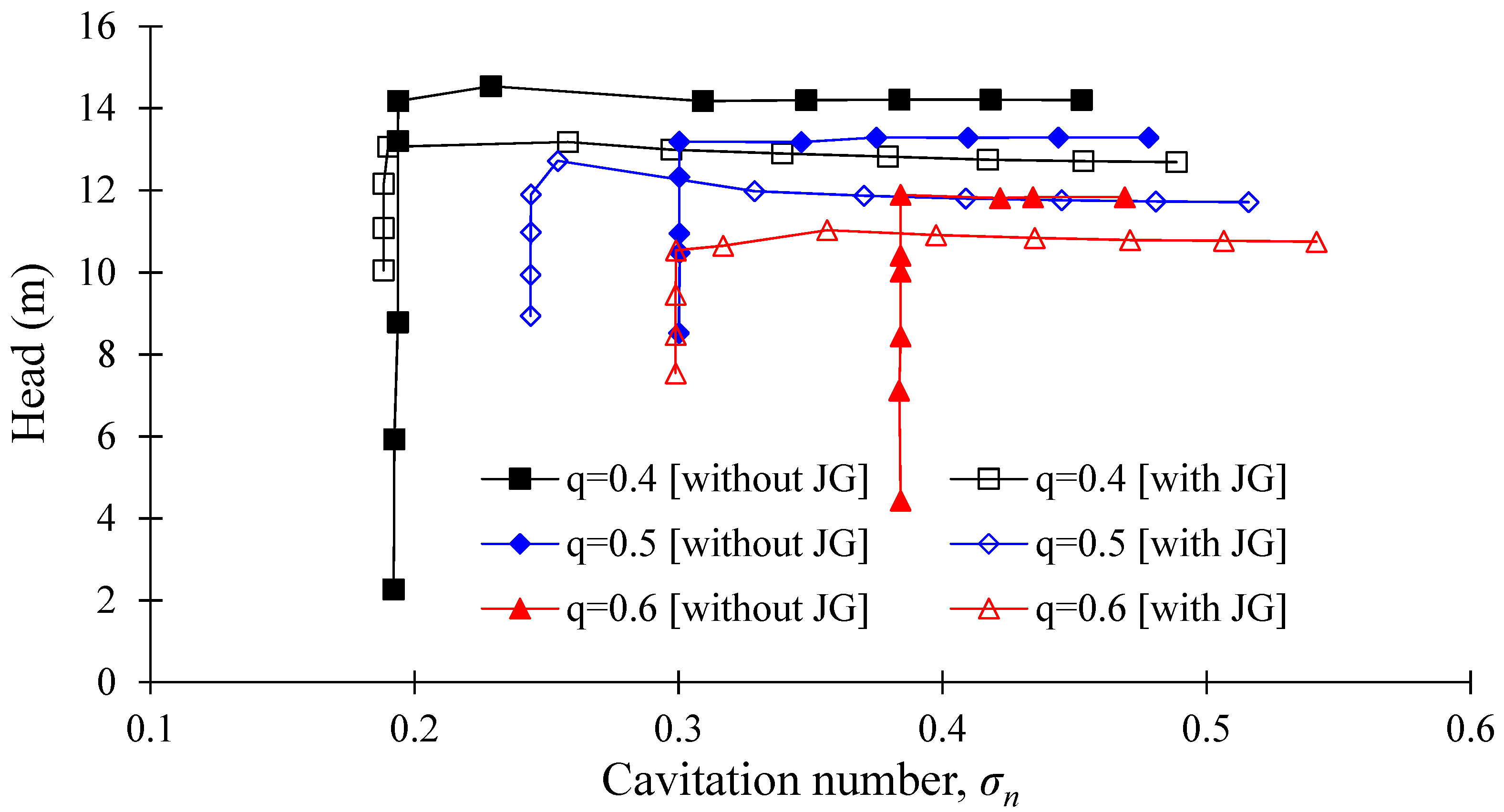
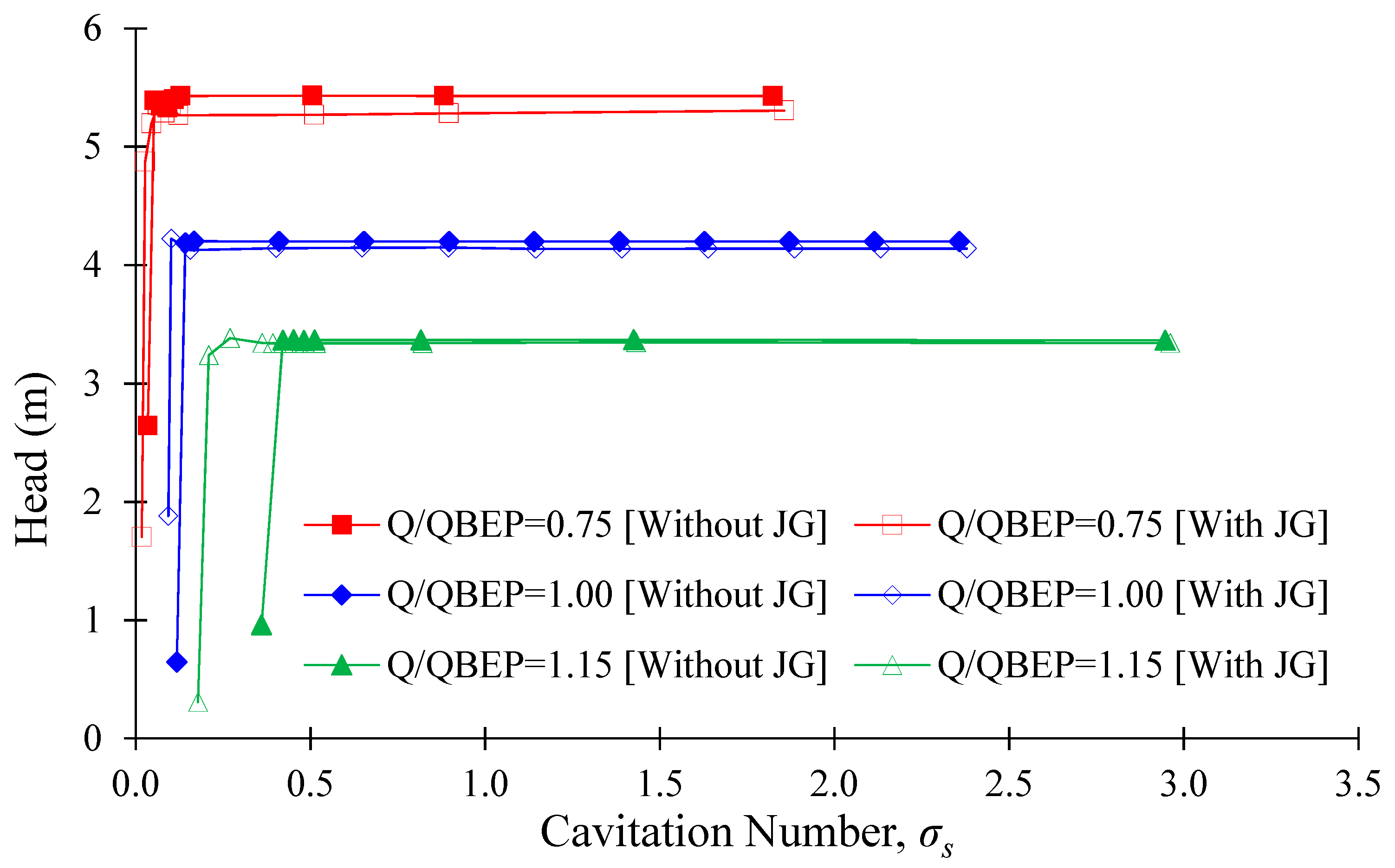
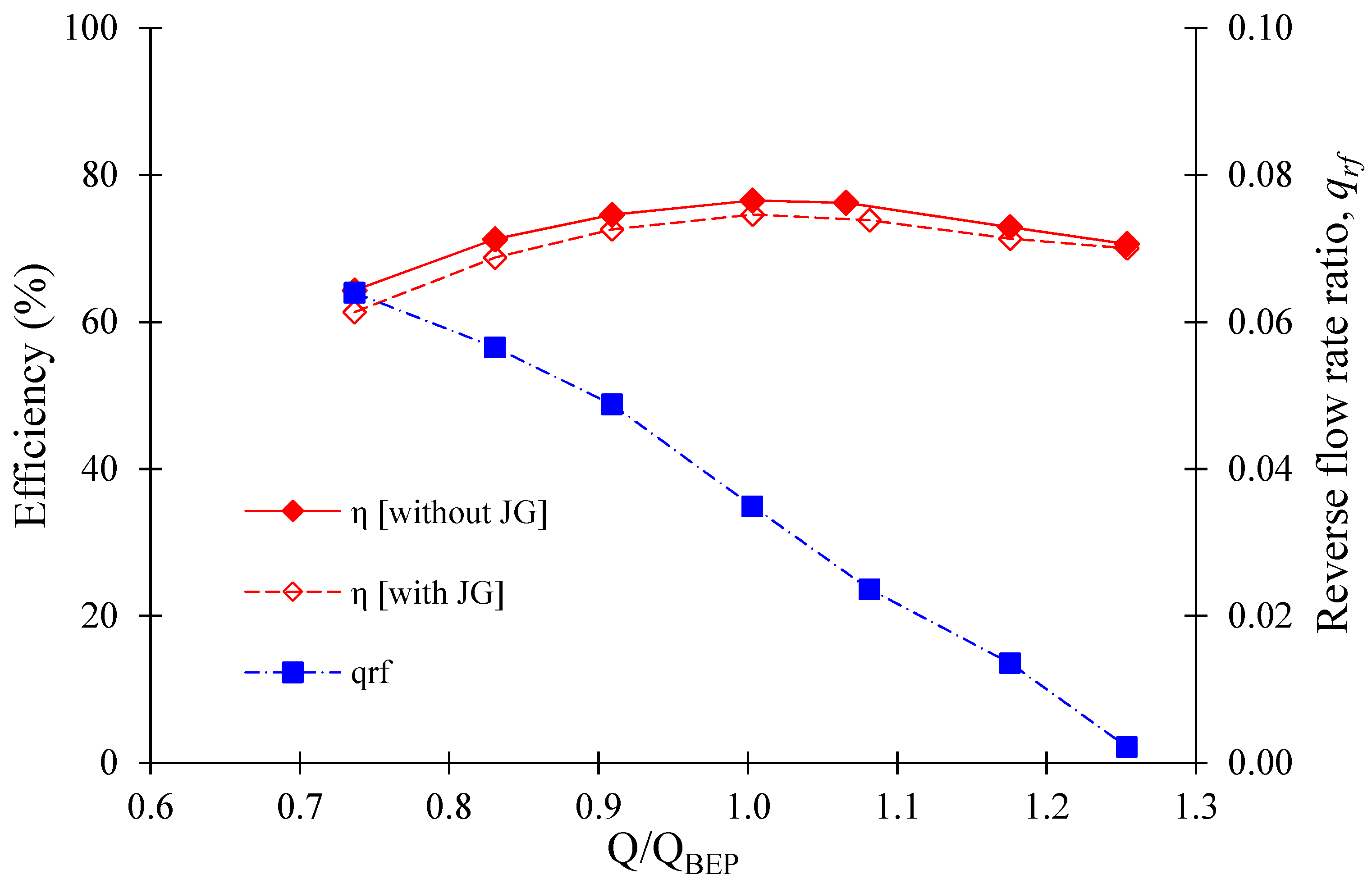
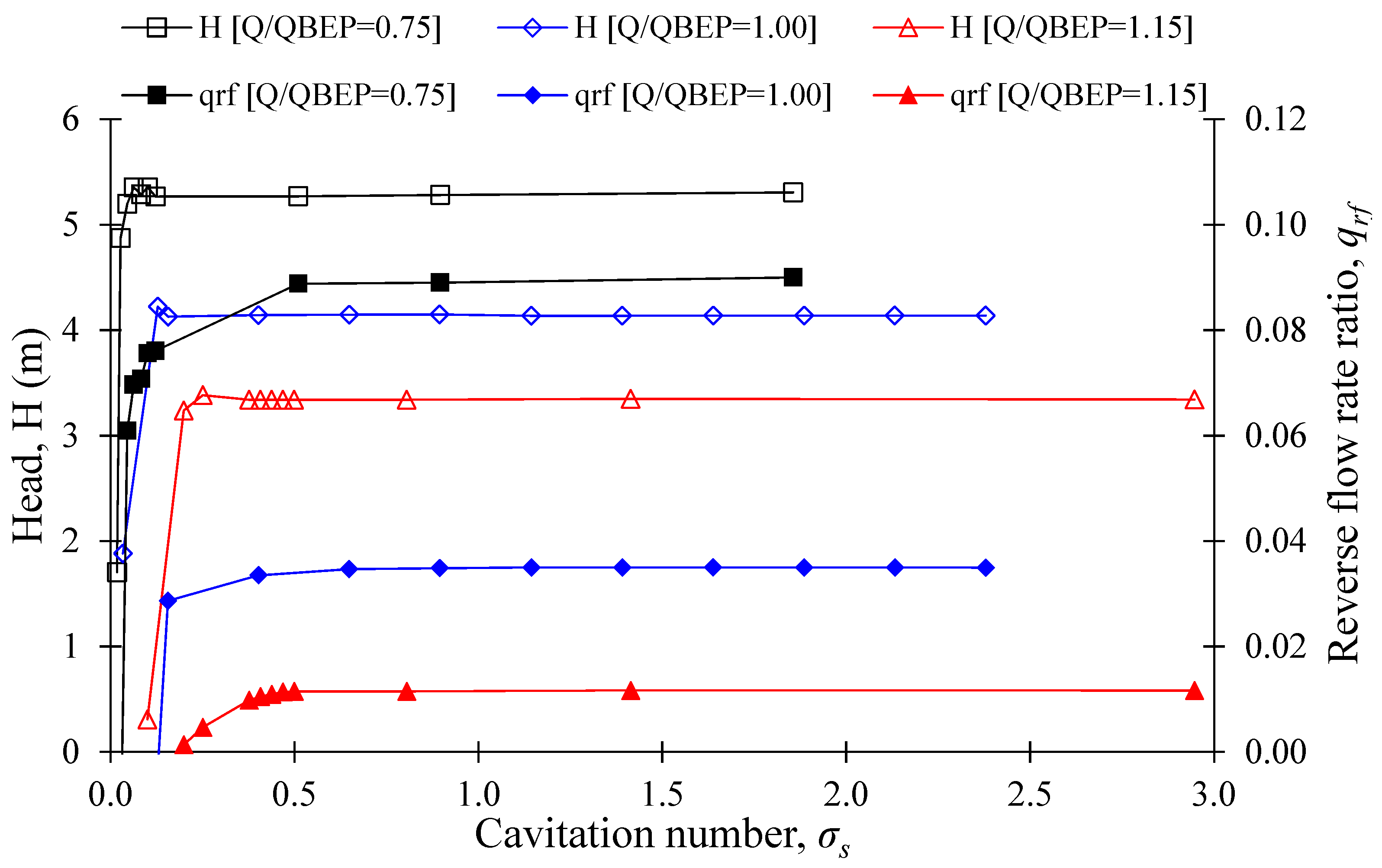
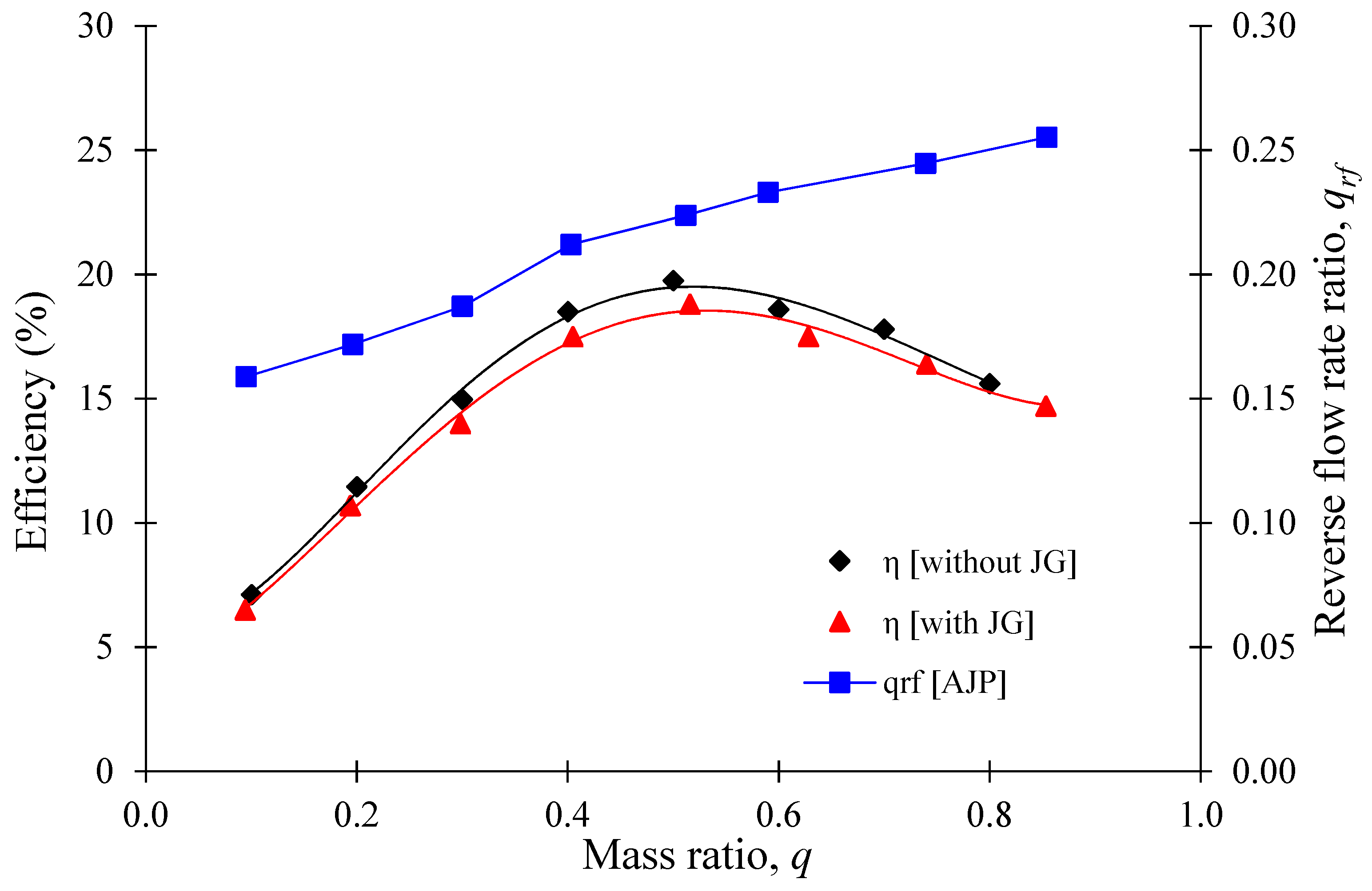
The CFD analysis showed that the J-Groove installation in the AJP and SCP models improves the suction performance. The pressure distribution and suction performance of AJP and SCP models are improved drastically with J-Groove installation. The reverse flow rate plays a significant role in suction performance improvement. The pressure distribution in the AJP and SCP models is different because of the impeller. In the AJP model, the reverse flow rate ratio increases with an increase in flow rate. However, the reverse flow rate ratio decreases with an increase in flow rate in the SCP model. The installation of the impeller has a significant impact on the reverse flow rate in the diffuser. In the AJP model, the pressure difference between the inlet and outlet of J-Groove is higher in full load conditions than in partial load conditions. The reverse flow rate is dependent on the pressure difference. In the SCP model, the pressure difference is larger at partial load conditions compared to full load conditions.
The suction performance is directly related to the reverse flow rate ratio. The study concluded that the reverse flow rate ratio is dependent on the pump type, flow rate, and cavitation number. The higher reverse flow rate ratio improves the suction performance in the AJP and SCP models effectively. The reverse flow mechanism in the AJP and SCP models is different. In the AJP model, the simple pressure difference between the inlet and outlet of J-Groove induces the reverse flow. In the SCP model, the rotation of the impeller causes a pressure difference between the suction and pressure side, which contributes to the reverse flow. It is concluded that the J-Groove installation helps to increase the reverse flow rate mainly due to the pressure difference.


