Article

Numerical Simulation and Experimental Test of the Sliding Core Dynamics of a Pressure Controlled Jet Crushing Tool for Natural Gas Hydrate Exploitation

1
School of Mechatronic Engineering, Southwest Petroleum University, Chengdu 610500, China
2
Guangdong Provincial Laboratory of Southern Marine Science and Engineering (Zhanjiang), Zhanjiang 524000, China
3
Energy Equipment Institute, Southwest Petroleum University, Chengdu 610500, China
*
Author to whom correspondence should be addressed.
Processes 2022, 10(5), 1033; https://doi.org/10.3390/pr10051033
Submission received: 1 April 2022 / Revised: 10 May 2022 / Accepted: 18 May 2022 / Published: 23 May 2022

Abstract

:
A pressure-controlled jet crushing tool (PJCT) for the exploitation of deep-sea natural gas hydrate (NGH) was invented to achieve sediment crushing and cavity creation. The opening and closing of tool is controlled by changing the internal flow rate remotely. It can realize the controllable continuous switching of the working state between horizontal well drilling and cavity creation. A dynamic simulation model of the sliding core was established based on the innovative design scheme of the PJCT and the motion law of its slide core was analyzed under the influence of spring stiffness, friction coefficient, and flow rate loading scheme. Moreover, an engineering prototype of the PJCT was manufactured so that a sliding core motion experiment of the prototype was carried out. When the drilling fluid flow rate reaches 455 L/min, the PJCT can stably complete the self-locking and unlocking functions. Its sliding core needs more time to stabilize with an increase in spring stiffness. Meanwhile, the PJCT could achieve continuous fast switching between the mechanical drilling state and the jet crushing state within a cycle of continuous flow changes. Finally, the kinematic and dynamic working mechanism of the PJCT is verified by the combination of the numerical simulation and the experimental analysis above.

1. Introduction

Due to its high energy density and wide distribution in the world, NGH is considered an ideal clean energy in the 21st century. According to the statistics of scholars, NGH has a carbon quantity twice that of all fossil fuels combined and exists on land in the polar region and offshore around the globe. Among them, non-diagenetic hydrates account for 76.5% of all hydrates [1,2,3,4]. The characteristics of non-diagenetic NGH are shallow burial depth, low consolidation strength, non-diagenesis, and metastable weakly cemented [5]. Traditional mining technology (such as the decompression method, thermodynamic inhibitor injection method, the CO2 replacement method, thermal stimulation method [6,7,8,9,10]) for non-diagenetic hydrate mining may break the phase equilibrium of the NGH reservoir, which leads to a large number of disordered decompositions of NGH, resulting in formation collapse and the release of a large volume of CO2 [11]. Based on the occurrence characteristics of non-diagenetic hydrates, the solid-state fluidized exploitation method, an innovative exploitation method, was proposed by Zhou [12], which is an effective way to realize safe and green mining of marine non-diagenetic natural gas hydrates. The core of this process is to make use of the characteristic of NGH whereby it can maintain phase equilibrium under temperature and pressure of the NGH reservoir and change the fragmentation and decomposition process of NGH from an uncontrollable state to controllable state. High temperature seawater on the sea surface is pumped into a wellbore to the crushing hydrate reservoir. NGH particles are then mixed with seawater and sucked into the closed pipeline. After that, the mixed slurry of NGH is preliminarily separated. Meanwhile, the resulting mud and sand is backfilled to the goaf of the reservoir, which can ensure the stability of the reservoir formation structure. Further, the initially separated NGH slurry is conveyed to an offshore platform through the closed pipeline. Finally, methane is extracted from the natural gas hydrate mixing paddle on the offshore platform. Figure 1 illustrates the schematic diagram of solid fluidization exploitation [13,14].
In 2017, the world’s first solid-state fluidization test production of NGH was successfully carried out in the Shen hu sea area of the South China Sea [12]. Jet crushing of the hydrate-bearing sediment was one of the core developments in the test production. However, the conventional jet crushing tool had some problems, such as being uncontrollable and non-reusable. In addition, using it requires replacing the drill string with multiple times, which greatly reduces the exploitation efficiency and increases the drilling cost and drilling risk [15]. Therefore, in order to solve the problems of existing jet crushing tools, Tang et al. [16,17] developed a series of pressure-controlled jet crushing tools for NGH exploitation. Further, the authors studied the internal flow field of the sliding core of the PJCT and found the relationship between pressure drop and axial force in the sliding core and the optimum design parameters of the sliding core. Furthermore, the motion law of the sliding core in various types of valves has been studied by many scholars. Zou et al. [18] analyzed the relationship between the closing velocity, closing time, and pressure difference in the check valve sliding core under different spring stiffness coefficients by using flow field analysis software. Roman et al. [19] used flow field analysis software to study the pressure field, the velocity field of the check valve in the steady state, and examined the unsteady state during the sudden opening and sudden closing process. Wang et al. [20] established a simulation analysis model based on the disturbance response characteristics of the spring oscillator of the unidirectional valve, and obtained a stable working range of the unidirectional valve. Li et al. [21] studied the influence of the check valve on the overall flow characteristics of the high-frequency reciprocating pump by establishing a dynamic model of the internal fluid and rigid body of the cone check valve. Lai et al. [22] investigated the transient characteristics, internal flow field of the double disc check valve, and transient characteristics during the opening period using the unsteady CFD method. Xiang et al. [23] analyzed the opening and closing characteristics of the passive shuttle check valve by establishing a dynamic model of the check valve. Lee et al. [24] carried out experiments on different types of check valves and used three types of transient comparison methods to investigate the dynamic behavior of check valves under pressure transient conditions.
These experiments and studies made a great contribution to the design and application of the continuous reciprocating valves in the conventional fluid transportation pipeline. At the same time, through their research methods, we found that establishing a dynamic simulation model of the sliding core movement process and analyzing the motion law of the sliding core had important guiding significance for the design and application of the valve. The PJCT is the key equipment for jet breaking and hole drilling in solid fluidization exploitation. Whether the sliding core of the PJCT can move to the predetermined position affects the opening and closing of the jet crushing nozzle in the jet crushing work.
However, to the best of our knowledge, no specific study addresses a motion law analysis of this kind of pressure-controlled jet crushing tool, which seriously limits the design and application of such tools. In order to meet the requirements for jet breaking and hole drilling in solid fluidization exploitation, it is necessary to study the motion law of this kind of tool. It is hoped that the deficiencies that exist in conventional jet crushing tools will be solved and the commercial application of the natural gas hydrate solid-state fluidization process is promoted with our proposed PJCT.
Therefore, we aim to test the feasibility of the PJCT by conducting research and experiments on the movement law of the sliding core. In this paper, we propose an innovative pressure-controlled jet crushing tool based on NGH solid fluidization exploitation. In Section 2, the structure of PJCT and the working process under different working conditions are introduced. For Section 3, the mathematical model of PJCT motion is proposed, and the simulation model and simulation parameters are established through multi-body dynamics software. The motion law of its slide core was obtained and analyzed under the influence of various factors in Section 4. Section 5 of this paper is mainly to carry out PJCT experiments and discuss experimental phenomenon and results. Finally, we provide some discussion and conclusion in Section 6.

2. Working Mechanism of PJCT

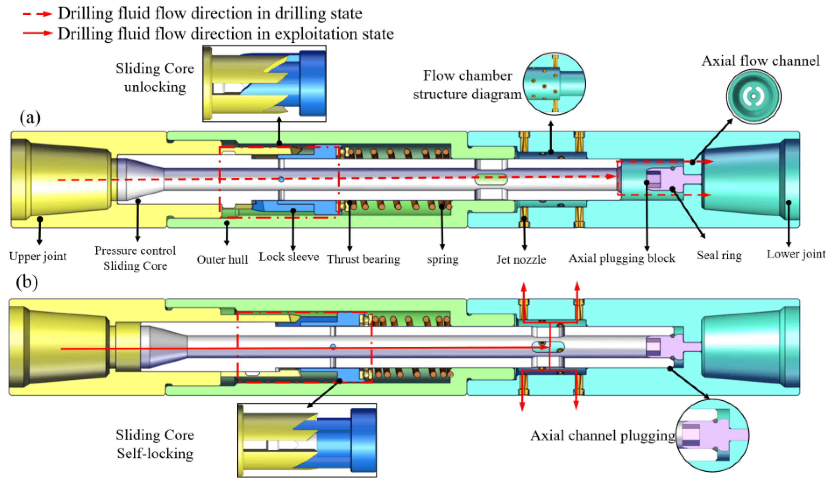
The basic principle of the PJCT is that when fluid passes through the suddenly narrowed pipeline, the fluid will produce a separated boundary layer on the wall of the pipeline and the vortex zone will form between the fluid and the wall due to the inertia of the flowing particles. It cannot make a sharp turn along the abrupt flow boundary. Numerous vortices of different scales continuously absorb energy from the fluid during the process of formation, movement, collision, and fragmentation, and the energy is eventually lost in the form of friction and collision. In addition, the appearance of the vortex region aggravates the pulsating velocity of the turbulent flow, which results in further loss of hydro mechanical energy [25,26]. Therefore, a pressure drop occurs in the change section of the pipe diameter. The pressure drop acts on the variable cross-section and forms an axial force, which is used as the driving force to control the sliding core movement of the PJCT. The specific structure of the self-locking PJCT is shown in Figure 2.

2.1. Working Process of PJCT

The working process of PJCT has three steps as follows:
  • Horizontal well drilling state: The flow rate of the drilling fluid is small and the driving force on the sliding core is less than the preload of the spring. The jet hole on the sliding core is blocked by the outer cylinder and is not connected with the jet nozzle. The drilling fluid flows down through the axial flow channel and flows out through the end of the bit for drilling.
  • Drag back tool string and jet crushing state: The down hole string is dragged back, and the drilling fluid rate is increased at the same time. The driving force of the sliding core gradually increases and then the compression spring further moves downward. At this time, the jet hole on the sliding core is exposed and connected with the jet nozzle, and the axial flow channel is blocked by the axial plugging block. The high-pressure drilling fluid starts the jet crushing operation through the jet nozzle. Meanwhile, the self-locking mechanism can avoid the fluctuation of the sliding core caused by the change in the drilling fluid rate and realizes the stability of the breaking process.
  • Multi-angle directional mining: when the dragging and acquisition of the drill string is completed, the drilling fluid rate is gradually reduced to 0 L/min, and then the drilling fluid flow is increased to the jet breaking flow again. During this time, the self-locking mechanism is unlocked, and then the drilling fluid flow is reduced. The sliding core rebounds under the action of spring force. The jet nozzle is closed and drilling fluid flows again towards the bit end through the PJCT. Then the whole down hole tool will change in another direction at the bottom of the wellbore to repeat horizontal well drilling and drag back the tool string and jet crushing. Finally, multi-angle, large-scale mining can be realized.

2.2. Working Process of the Self-Locking Mechanism

The self-locking mechanism consists of an upper joint, sliding core, locking sleeve and thrust bearing, as shown in Figure 3a. The positioning slot, locking slot, unlock slope, and locking slope are set on the upper joint. The auxiliary slope is set on the pressure control sliding core. The guide slope is set on the locking sleeve. The working process of the self-locking mechanism has four steps as follows:
  • When the solid-state fluidized exploitation is in the horizontal well drilling state, the self-locking mechanism is in the initial state, as shown in Figure 3a. The locking sleeve is located in the positioning slot, and the guide slope is located in the middle of the auxiliary slope.
  • When the solid-state fluidized exploitation is in the jet crushing state, the drilling fluid flow is increased to the self-locking mechanism opening flow. The sliding core pulls the locking sleeve out of the positioning slot under the action of the drilling fluid, the locking sleeve moves along the auxiliary slope to the lowest end of the auxiliary slope and turns to a certain angle under the action of the thrust bearing as shown in Figure 3b.
  • When the drilling fluid flow suddenly decreases or fluctuates, the locking sleeve moves along the locking slope to the lowest end of the locking slot under the action of the spring and the thrust bearing. The self-locking mechanism enters the self-locking state as shown in Figure 3c.
  • When the jet crushing state is completed, the self-locking mechanism needs to be released from the locked state. First, the drilling fluid flow is reduced to 0 L/min and then the flow to the jet crushing flow is loaded. After that, the drilling fluid flow is gradually reduced to 0 L/min. In this process, the locking sleeve is pushed out of the locking slot, and the locking sleeve moves along the auxiliary slope to the lowest end of the auxiliary slope under the action of the sliding core, as shown in Figure 3d. After that, the locking sleeve enters the positioning slot along the unlock-slope, and the self-locking mechanism returns to the initial state as shown in Figure 3a. So far, the self-locking mechanism has carried out a complete working process.
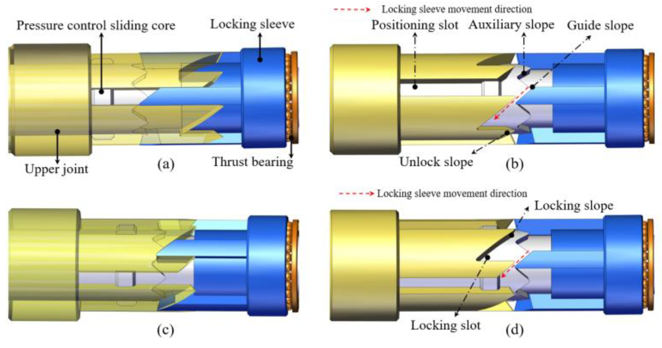
Figure 3. Working process of the self-locking mechanism: (a) the initial state of self-locking mechanism; (b) Self-locking process of self-locking mechanism; (c) the locked state of self-locking mechanism; (d) Unlocking process of the self-locking mechanism.
Processes 10 01033 g003

3. Motion Analysis of the Sliding Core

3.1. Mathematical Model

The motion of the sliding core is controlled based on the motion differential equation established by Newton’s second law and the interaction between the fluid force and the sliding core. At the same time, the sliding core of the PJCT hardly deforms during use. The deformation is negligible relative to the movement of the fluid, so the following assumptions are made for the sliding core:
  • Consider the sliding core as a rigid body and ignore its small deformation;
  • Consider the gravity of the sliding core and the friction between the sliding core and the parts of PJCT.
Based on the above assumptions, we combined Newton’s second law and established the sliding core motion differential equation:
m h x × d d t ( v e l h x ) = F l t F s p r i n g f
where m h x is the slide core mass, k g ; v e l h x is the velocity of the sliding core, m / s ; F l t is the force of the drilling fluid on the sliding sore, N ; F s p r i n g is the spring force, N ; f is the friction between the sliding core and other parts, N .
The variation rate of the sliding core velocity can be obtained by using the differential principle for the displacement relationship between the next moment and the previous moment.
d ( v e l h x ) d t = v e l h x _ n e w v e l h x _ o l d t s t e p
The acceleration of the sliding core motion can be obtained by using the differential of the sliding core vector velocity in Equation (1). The differential relationship between the sliding core velocity and the motion displacement can be established as follows:
v e l h x _ n e w = d h x _ n e w d h x _ o l d t s t e p
where new is the subscript of the physical quantity at the moment before the sliding core movement, old is the subscript of the physical quantity at the moment after the sliding core movement, t s t e p is the time interval of the sliding core movement.
Combining Equations (1) and (2), the elastic force of the sliding core is obtained by using the displacement obtained by the equation, and the relationship between the displacement change and the force in the final sliding core movement process is obtained:
d h x _ n e w = ( v e l h x _ n e w ) 2 ( v e l h x _ o l d ) 2 2 × F l t F s p r i n g f m h x
Through the above equation, the balance relationship of fluid force, spring force, and friction force in the process of the sliding core movement can be obtained, and the real simulation of the sliding core movement can be realized.

3.2. Numerical Simulation

Multi-body dynamics simulation software is a widely used mechanical system simulation software. Virtual prototypes can be built and tested in software to understand the motion performance of complex mechanical system designs. It is an effective means to improve design efficiency and reduce tool development costs.
In this paper, 3D design software was used in the model design of the prototype and multi-body dynamics simulation software was used to build the dynamic simulation model of PJCT. First, 3D models of the PJCT were drawn. After that, the PJCT assembly model was saved in a ‘Parasolid’ format, and the 3D model was imported into multi-body dynamics simulation software. In the software, the mass attributes, length, and the center of mass of each part in the 3D model are edited to define and ensure the virtual prototype matches the real physical characteristics. Among them, steel was selected as the material for parts. The constraints of the components and the kinematic pair relationship were set as shown in Table 1.
According to the pressure drop formula of the reducing section of the suddenly narrowed pipeline, the driving force generated by different flow rates on the sliding core can be obtained [17]. After that, the calculation results were input into the multi-body dynamics simulation software as one of the calculation conditions, and the spring preload was set at 145.47 N (the driving force generated when the maximum flow rate in the horizontal drilling stage is 300 L/min). Finally, when the loading flow changes continuously, the sliding core is subjected to the driving force generated by the drilling fluid and also changes with time. The “STEP” function in the multi-body dynamics simulation software was used to describe the driving force change with time.
Using the flexible connection function in multi-body dynamics simulation software, which can define spring damping coefficients and stiffness coefficients, we replaced the spring model. The dynamic simulation model of PJCT is shown in Figure 4.

4. Dynamic Simulation Results

4.1. Motion Law of the Sliding Core under Different Spring Stiffness and Flow Rate

4.1.1. Displacement Change Law of the Sliding Core

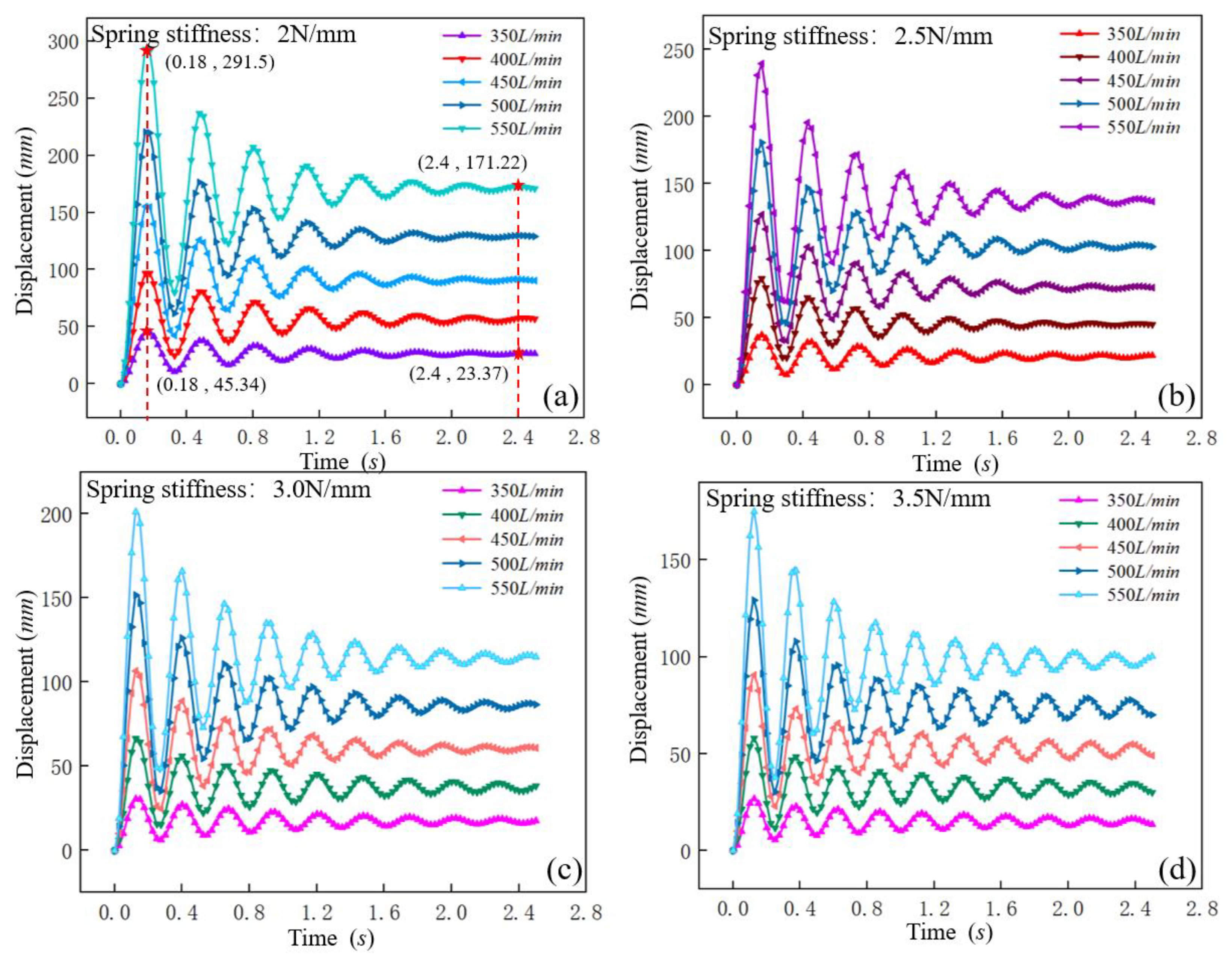
Spring stiffness was set to 2 N/mm (Figure 5a), 2.5 N/mm (Figure 5b), 3 N/mm (Figure 5c), 3.5 N/mm (Figure 5d), respectively. The influence of spring stiffness on the displacement of the sliding core during transient opening was analyzed under different drilling fluid flow rates of 350 L/min, 400 L/min, 450 L/min, 500 L/min, 550 L/min on the transient opening displacement of the sliding core. We obtained the change rule of the sliding core movement displacement value with time as shown in Figure 5.
As shown in Figure 5, when the spring stiffness was constant, the maximum displacement and the final stable displacement of the sliding core gradually increased with the increase in drilling fluid flow, but the time to reach the maximum displacement did not change. According to the statistics of special points in Figure 5a, when the flow rate increased from 350 L/min to 550 L/min, the maximum displacement of the first sliding increased from 45.34 mm to 291.5 mm, with an increase of 84.44%. The displacement of the sliding core after stabilization also increased from 23.37 mm to 171.22 mm. This is because the impact force received by the sliding core increases with the gradual increase in the drilling fluid flow rate, which further increases the maximum displacement of the opening and closing of the sliding core. The variation law of the sliding core displacement shows the feasibility of changing the flow to realize the opening of the PJCT. When the flow rate of drilling fluid was constant, with the increase in spring stiffness, the maximum displacement of the sliding core gradually decreased. The difference between the maximum wave crest and the minimum wave trough also decreased. However, the time that the sliding core tended to be stable was increased and the stability became worse. The corresponding time to stabilize increased from 1.675 s to 2.275 s. The variation laws indicated that when the return spring is designed, in order to ensure the stability of the sliding core, the stiffness of the spring should not be too large.

4.1.2. Velocity Change Law of Sliding Core

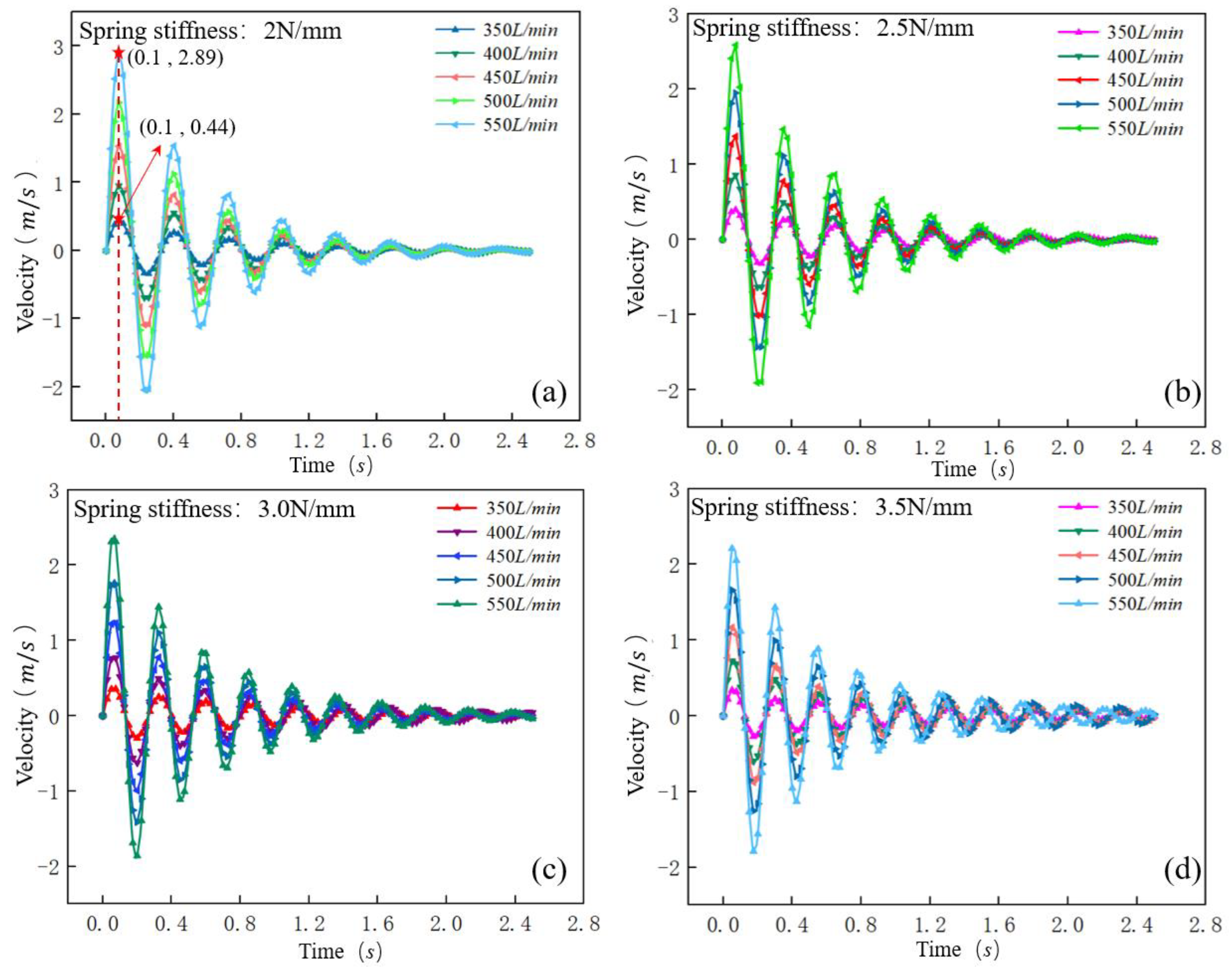
Spring stiffness was set to 2 N/mm (Figure 6a), 2.5 N/mm (Figure 6b), 3 N/mm (Figure 6c), 3.5 N/mm (Figure 6d), respectively. The influence of spring stiffness on the velocity of the sliding core during transient opening was analyzed under different drilling fluid flow rates of 350 L/min, 400 L/min, 450 L/min, 500 L/min, 550 L/min on the transient opening displacement of the sliding core. We obtained the change rule of sliding core movement displacement value with time as shown in Figure 6.
As shown in Figure 6, when the spring stiffness was constant, with the gradual increase in drilling fluid flow, the fluctuation range of the sliding core velocity gradually increased, but the time that the sliding core velocity tended to be stable was almost unchanged. According to the statistics of the special points in Figure 6a, when the spring stiffness was 2 N/mm, the flow rate increased from 350 L/min to 550 L/min, and the maximum velocity of the sliding core increased from 0.44 m/s to 2.89 m/s. However, the sliding cores always tended to be stable under the four different drilling fluid flow rates after fluctuating for 2 s. The result indicates that the fluctuation time of the sliding core is hardly affected by the drilling fluid flow rate. The velocity fluctuation amplitude of the sliding core gradually decreases with the increase in spring stiffness under the same flow rate, but the time that the sliding core tends to be stable increases. The special point statistics of Figure 6a,d show that the time for the sliding core to stabilize was extended from 1.8 s to 2.4 s. When the drilling fluid flow rate was 500 L/min and the spring stiffness increased from 2 N/mm to 3.5 N/mm, which indicates that the amplitude of the sliding core fluctuation velocity will gradually decrease, and the stability of the sliding core fluctuation will gradually decrease under the constant flow rate and with the increase in the spring stiffness.

4.2. Motion Law of the Sliding Core under Different Friction Coefficients

4.2.1. Displacement Change Law of the Sliding Core

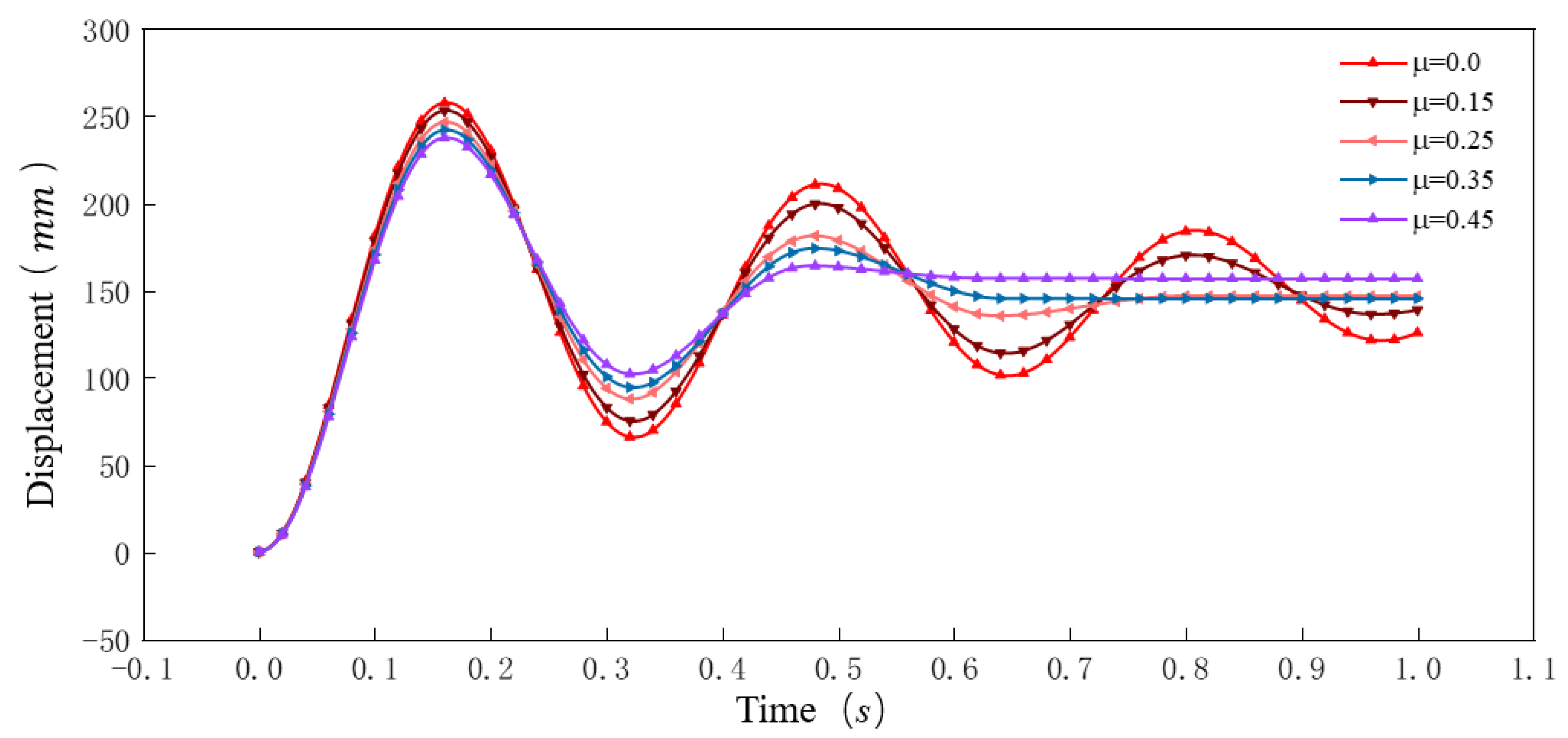
The influence of the friction coefficient between the PJCT parts and the sliding core on the movement process of the sliding core was analyzed under the same drilling fluid flow rates, spring stiffness, and the same sliding core material. The results of the analysis are shown in Figure 7.
As shown in Figure 7, the maximum displacement of the sliding core during the first movement gradually showed a decreasing trend with the increase in the friction coefficient, but the decrease in the maximum displacement of the sliding core was smaller. This result shows that the coefficient of friction between the components has little effect on the start-up of the sliding core. In addition, with the increase in friction coefficient, the fluctuation range and fluctuation time of sliding core displacement gradually decreased. When the friction coefficient was 0~0.15, the sliding core was in a fluctuating state after moving for 1 s. When the friction was 0.25~0.45, the sliding core was stable at 0.6 s. The analysis results show that the fluctuating displacement of the sliding core will gradually reduce, and the time required for the sliding core to move from fluctuation to stability will be reduce, as the friction coefficient increases. This is because the sliding core is not only affected by the spring, but also affected by the friction force between the sliding core and other components during the process of stabilizing the sliding core. Therefore, when the friction coefficient between the parts is large, the energy consumed by friction will increase, and the sliding core is more likely to be stabilized.

4.2.2. Velocity Change Law of the Sliding Core

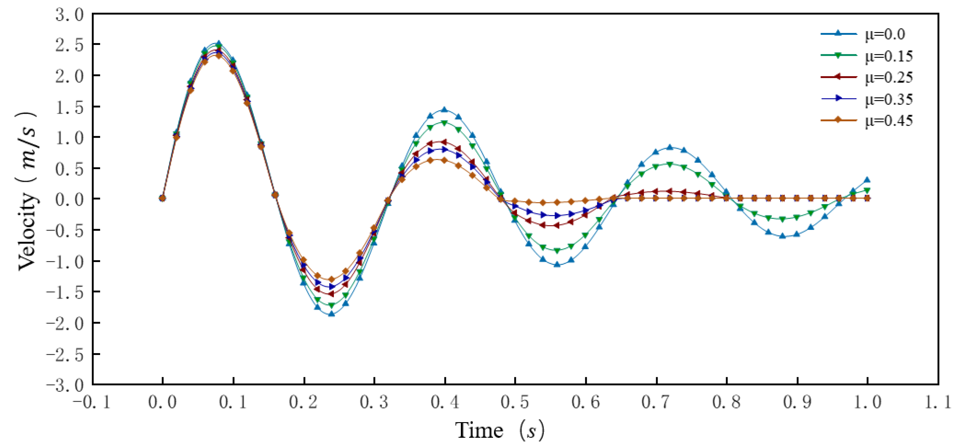
As shown in Figure 8, the maximum velocity of the sliding core fluctuation was almost constant under different friction coefficients, and the sliding core at the beginning of the movement had the same kinetic energy. However, after reaching the maximum moving velocity, the variation law of the sliding core velocity under different friction coefficients was different. Specifically, when the friction coefficient was 0~0.15, due to the lesser friction coefficient, the energy consumed by friction during the movement of the sliding core was small, thus the velocity of the sliding core fluctuated greatly, the fluctuation range decreased slowly, and fluctuated after moving for 1 s. When the friction coefficient was 0.25~0.45, with the increase in the friction coefficient, the kinetic energy of the sliding core increased losses due to increased friction, and the amplitude of the velocity fluctuation of the sliding core was greatly reduced rapidly. So, the velocity of the sliding core approached 0 m/s at 0.6 s. This result shows that the fluctuation amplitude of the sliding core movement velocity will gradually decrease, and the time required for the sliding core to stabilize will be smaller, as the friction coefficient increases.
As shown in Figure 7 and Figure 8, the motion process of the sliding core was closely related to the friction force of the sliding core. Under the same flow rates and spring stiffness, the velocity fluctuation range and displacement of the sliding core was correspondingly smaller and the time of sliding core tended to stabilize was less with an increase in the friction coefficient. However, the driving force of the sliding core was mainly related to the drilling fluid flow rate. It became more difficult to open the sliding core as the friction was too large, which will increase the load of the drilling pump. Therefore, in the PJCT design process, it is necessary to appropriately control the friction between the sliding core and the rest of the components while ensuring the fast and stable response of the sliding core.

4.3. Motion Law of the Sliding Core under Different Flow Rate Loading Schemes

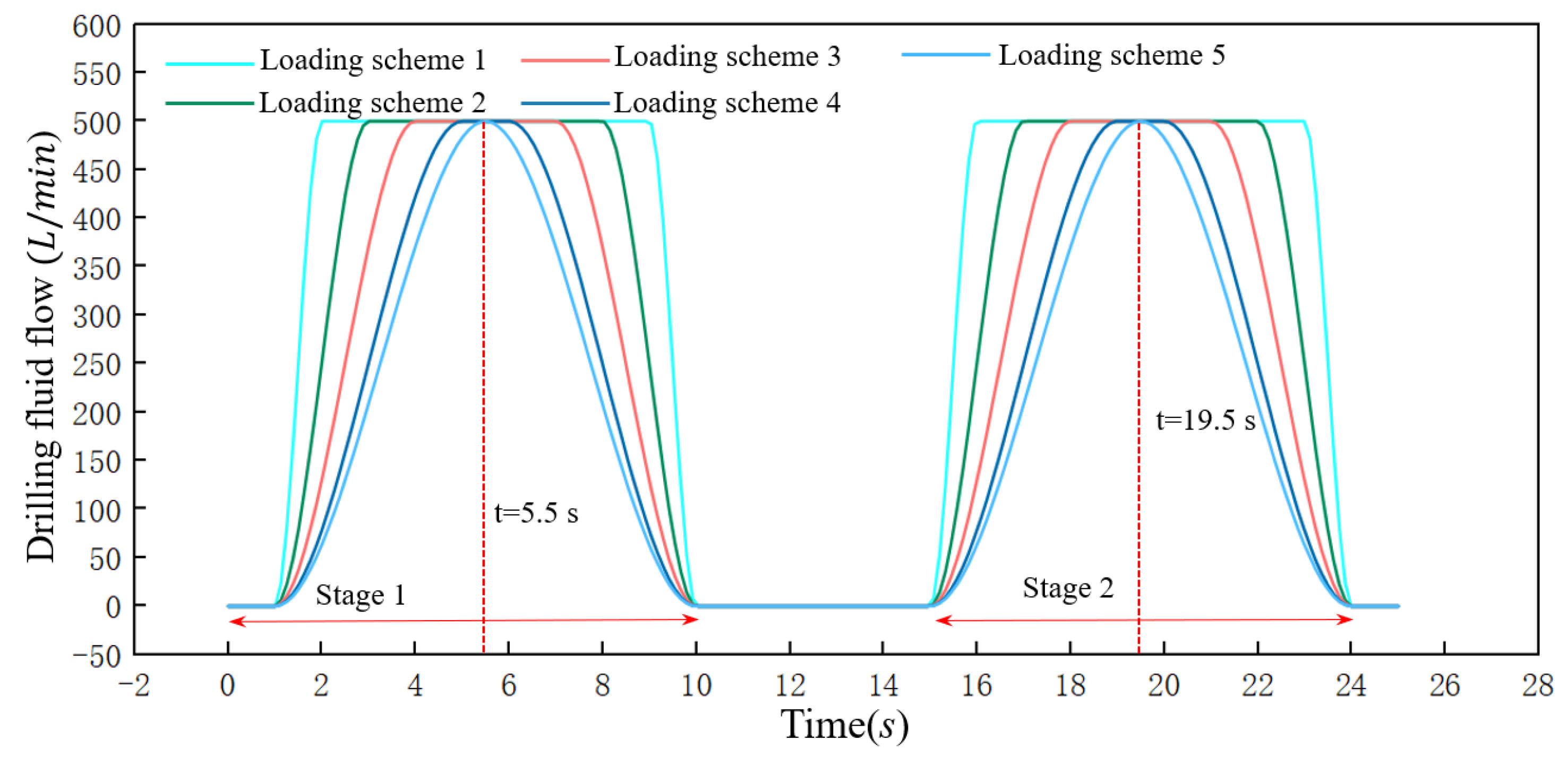
In order to simulate the loading scheme of the drilling fluid in practical engineering, we set up continuously changing drilling fluid flow rates under five different loading schemes. The movement law of the sliding core was analyzed in a drilling fluid loading cycle. Five different flow loading schemes are shown as Figure 9.
As shown in Figure 9, the loading process of the drilling fluid was mainly divided into stage 1 and stage 2. Stage 1: the time between 0~10 s was the self-locking stage of the sliding core. Stage 2: the time between 15~25 s was the unlocking stage of the sliding core. Furthermore, each stage was divided into a fluid loading phase and unloading phase. The five drilling fluid flow loading schemes were different in flow loading velocity, among which loading mode 1 had the fastest loading velocity and loading mode 5 had the slowest unloading velocity. Drilling fluid flow increased from 0 L/min to 500 L/min in the loading phase of stage 1. Loading scheme 5 needed 4.5 s to complete the process, while loading scheme 1 only needed 1 s. During the loading phase of stage 1, the locking sleeve slides out of the positioning slot and rotates at a certain angle to stay above the locking slot. When the drilling fluid flow decreased from 500 L/min to 0 L/min it enters the unloading phase of stage 1. Loading scheme 5 needed 4.5 s to complete the process and loading scheme 1 only needed 1 s. During the unloading phase of stage 1, the axial force on the sliding core decreased gradually. The locking sleeve rebounded under the action of the return spring and slid along the locking slope to complete self-locking. When the flow rate of drilling fluid increased from 0 L/min to 500 L/min in the loading phase of stage 2, the locking sleeve slides out of the locking slot and rotates at a certain angle to stay above the top of the unlock slope. When the drilling fluid flow rate was reduced from 500 L/min to 0 L/min in the unloading phase of stage 2, the locking sleeve slid along the unlock slope and slid into the positioning slot to complete the unlocking of the sliding core under the action of reset spring.
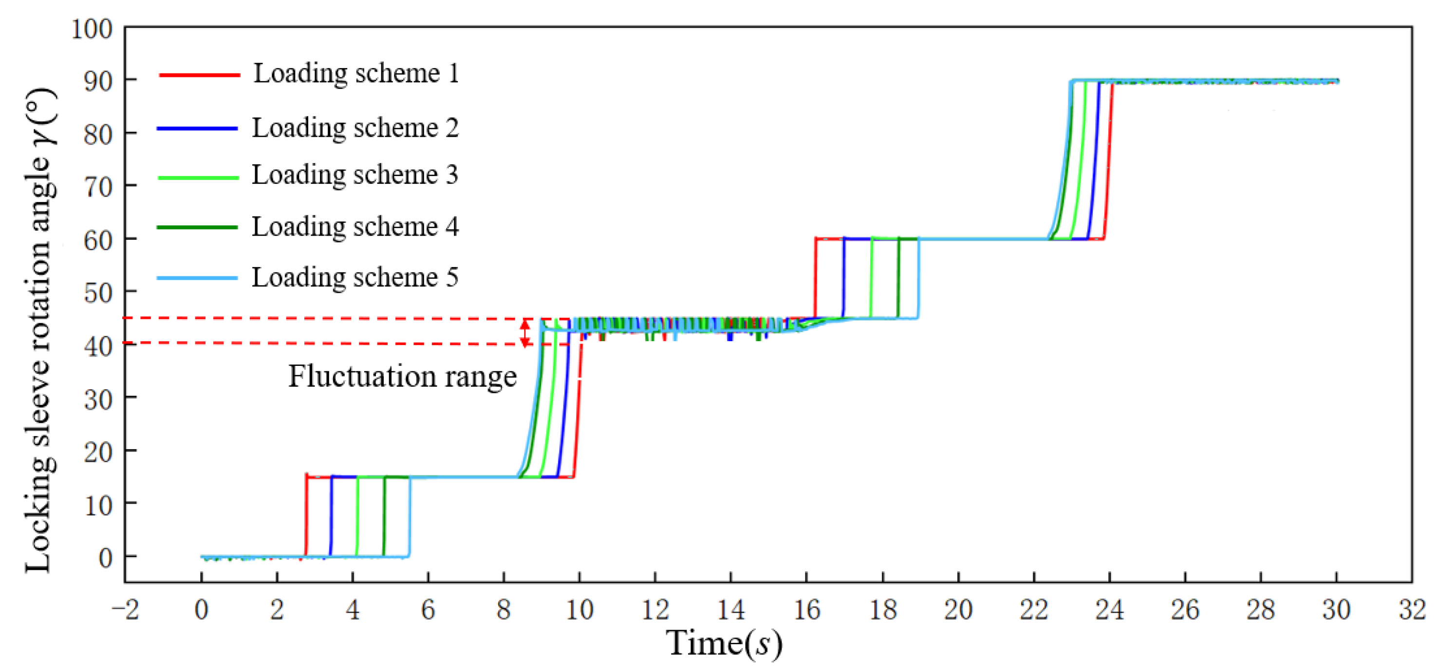
During the working process of the PJCT, the sliding core and the locking sliding sleeve are always in contact. We can verify the movement state of the sliding core by analyzing the change in the locking sliding sleeve rotation angle in a working cycle. The analysis results of the locking sleeve rotation angle under the five flow loading schemes are shown in Figure 10 in a working cycle.
As shown in Figure 10, the flow of drilling fluid increased gradually within 0~5.5 s and the locking sleeve was pulled out of the positioning slot under the action of the sliding core. The locking sleeve moved along the auxiliary slope to the lowest end of the auxiliary slope and rotated to 15°. Then, the flow of drilling fluid decreased gradually within 5.5~10 s. After the locking sleeve moved along the locking slope to the lowest end of locking slot, the self-locking mechanism entered the self-locking state and the sleeve rotated to 45° at this time. The locking sleeve was in a small fluctuation state within 10~15 s, but the locking sleeve was still in the locking slot. After that, the drilling fluid flow rate increased gradually again within 15~20 s, and the locking sleeve was pushed out of the locking groove. It moved along the auxiliary slope to the lowest end and rotated to 60°. At this time, the locking sleeve moved out of the self-locking groove and kept the angle of 60° under the action of drilling fluid. Finally, when the drilling fluid gradually decreased within 20~25 s, the locking sleeve entered the positioning slot along the unlock slope and rotated to 90°. At this time, the self-locking mechanism realized the lock release and completed a working cycle. The analysis results indicate that although the time when the self-locking mechanism starts to work is different, the self-locking mechanism can stably complete self-locking and unlocking under five different flow loading schemes.

5. Experiment Test

In order to verify whether the PJCT can complete the scheduled function, all parts of the PJCT were machined (as shown in Figure 11a) and the experimental engineering prototype (as shown in Figure 11b) was assembled. The main equipment involved in the experiment is shown in Figure 12.

5.1. Experimental Principle

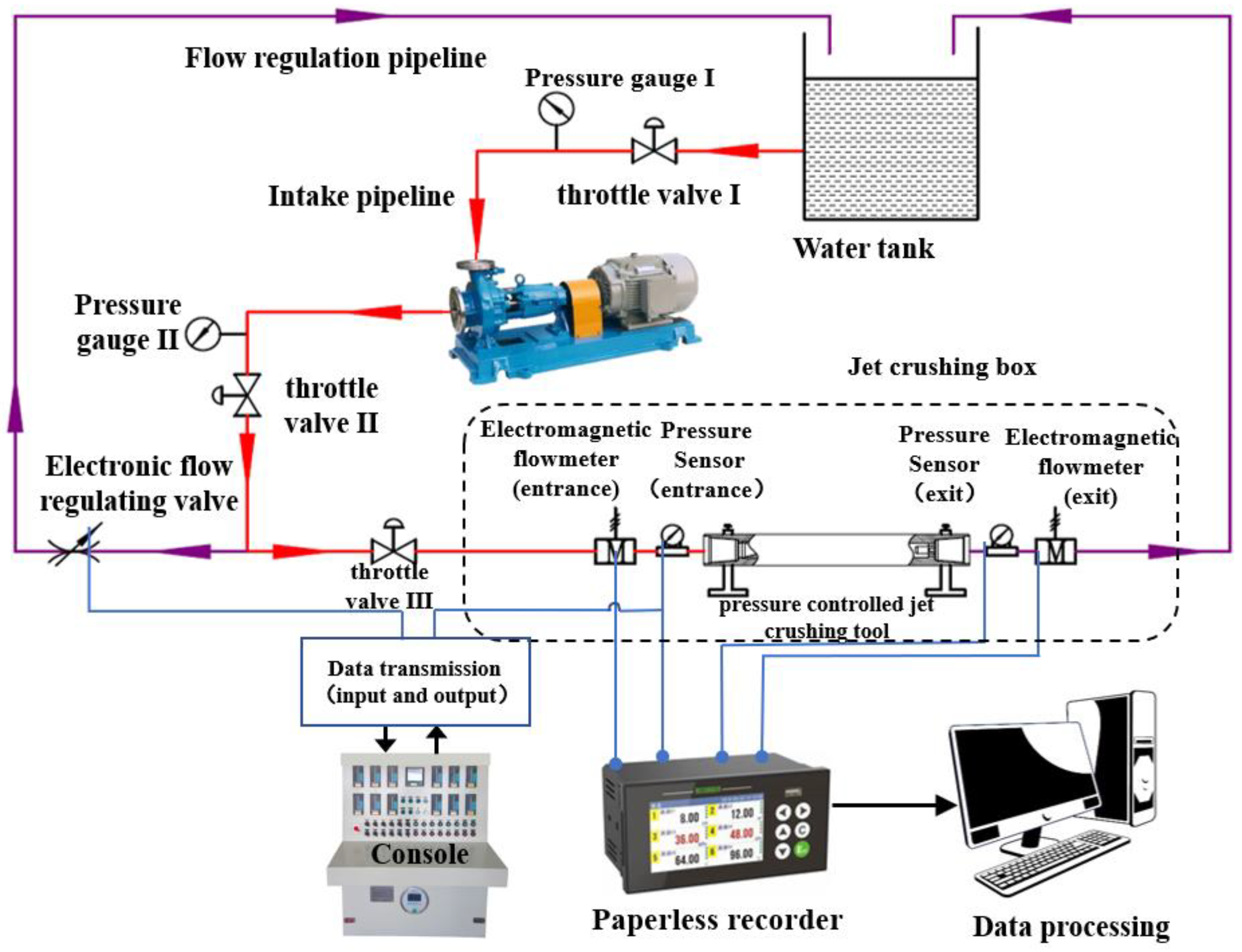
Figure 13 shows the schematic view of the experimental apparatus. Drilling fluid for the entire experimental system (including PJCT) was provided by a multistage pump system. The water was pumped out from the tank by the multistage pump system and entered the PJCT through throttle valves II and III, and then returned to the tank through the return pipeline. During the experiment, the opening of the electronic throttle valve on the bypass could be adjusted through the console. When the opening of the electronic throttle valve increased, the flow rate in the PJCT pipeline decreased. When the opening of the electronic throttle valve decreased, the flow rate in the PJCT pipeline increased. Apart from this, electromagnetic flowmeters and pressure sensors which were installed on the pipeline of the PJCT’s inlet and outlet were used to measure the actual pressure change inside the PJCT accurately. A total of four groups of experiments were carried out, and the flow loading schemes are shown in Table 2.
In the experiment, to ensure the accuracy of experimental data and consider the delay of data transmission when adjusting the flow rate in pipeline, the opening of the electronic throttle valve should be adjusted according to different drilling fluid flow levels, which is mainly divided into three stages as follows:
(1)
When the inlet flow rate is less than 300 L/min, the opening of the electronic flow control valve can increase by 7% each time. When the flow rate is stable, the corresponding experimental data and experimental phenomena should be observed and recorded before continuous adjustment.
(2)
When the inlet flow rate is between 300 L/min and 400 L/min, the opening of the electronic flow control valve can be increased by 5% each time. When the flow rate is stable, the corresponding experimental data and experimental phenomena can be observed and recorded before continuous adjustment.
(3)
When the flow rate is greater than 400 L/min, the opening of the electronic flow control valve can be increased by 3% each time, and the flow rate can be gradually increased until the nozzle is fully open.

5.2. Experimental Phenomena and Analysis

5.2.1. Experiment I

The experimental results and phenomena in Experiment I are shown in Figure 14 and Figure 15.
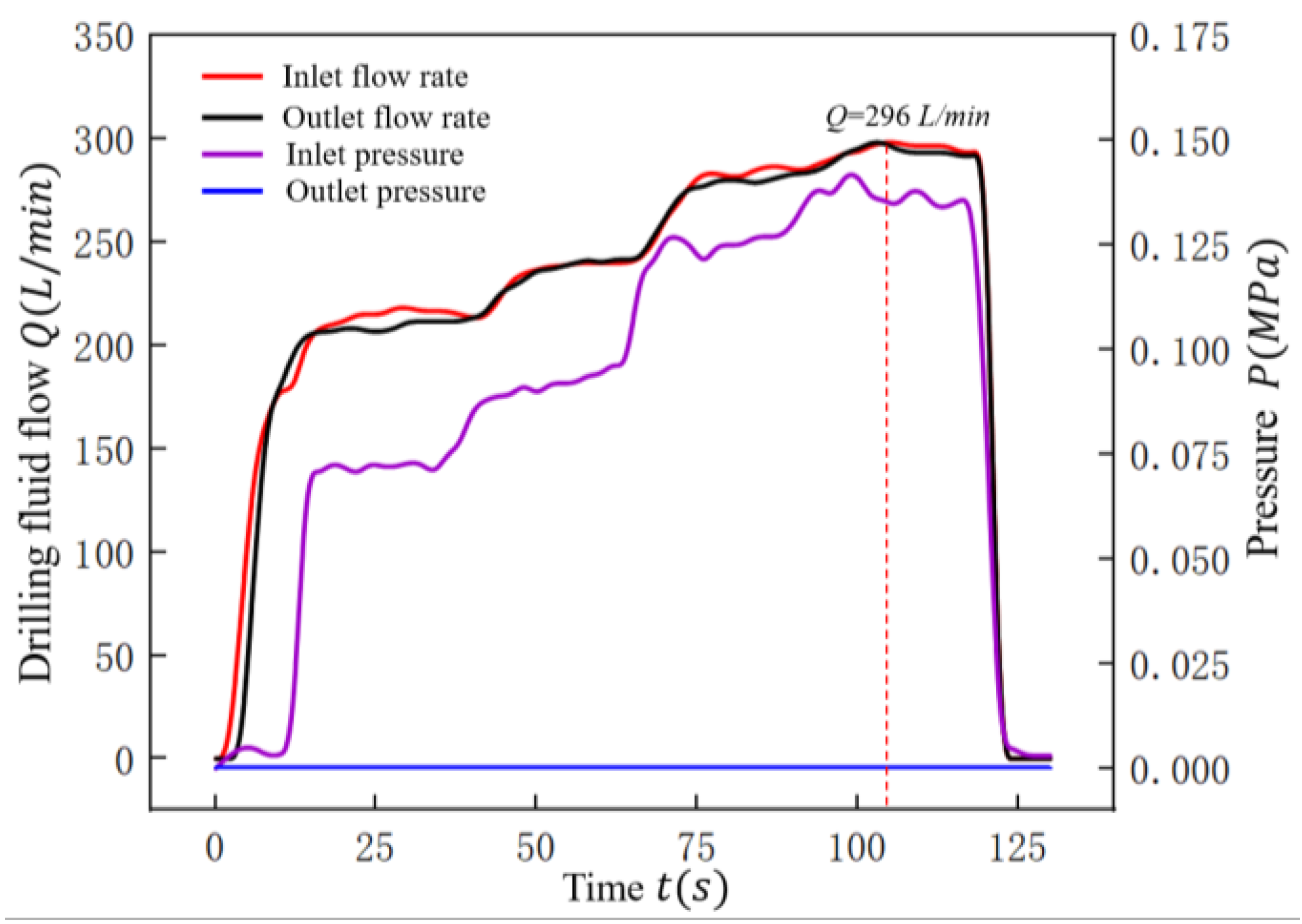
The flow rate range of experiment I was 0~300 L/min. Figure 14 shows that the maximum flow rate of 296 L/min was achieved at 114 s. At this time, the inlet drilling fluid pressure was 0.134 MPa, the outlet drilling fluid flow was 293 L/min and the outlet pressure was 0 MPa. It can be seen from Figure 15a–c that the nozzles did not be open in the whole process, which indicates that the sliding core will not slide to the nozzle opening position when the flow rate is less than 300 L/min.

5.2.2. Experiment II and Experiment III

The experimental results and phenomena in Experiment II and Experiment III are shown in Figure 16, Figure 17 and Figure 18. Figure 16 and Figure 17 show the variation in pressure and drilling fluid flow with time in PCJT during Experiment II and experiment III and the experimental phenomenon in the process of Experiment II and Experiment III are shown in Figure 18.
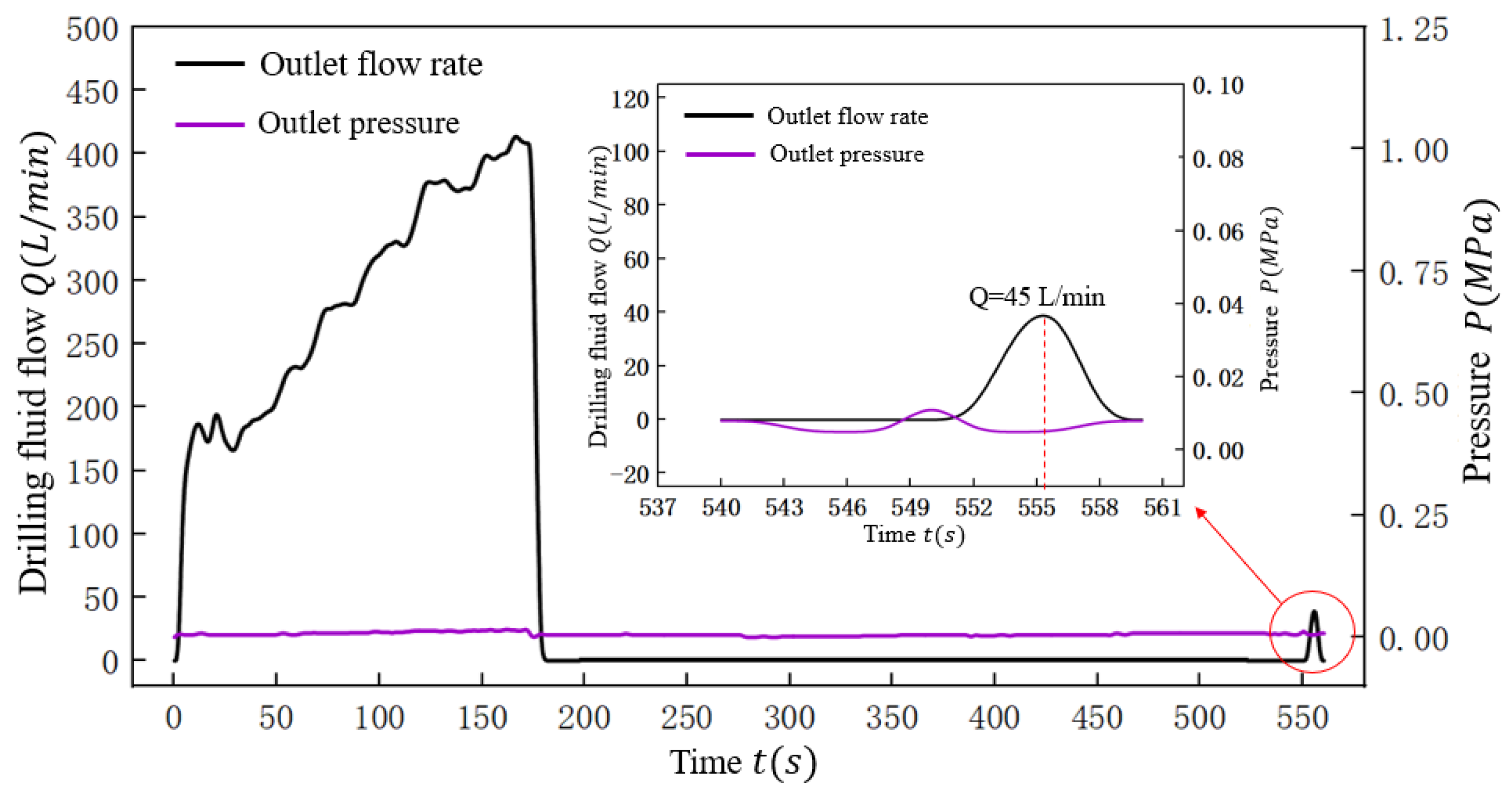
As shown in Figure 16, in stage 1, when the inlet flow was gradually increased to 470 L/min, the nozzle on the tool was gradually opened, which indicates that the sliding core starts to move axially according to the predetermined design. When the flow reached 453 L/min, the outlet flow rate suddenly decreased to 0 L/min and the inlet pressure rose from 0.255 MPa to 0.908 MPa suddenly. At that moment, the jet nozzle was completely opened, as shown in Figure 18 at 170 s. In stage 3, as shown in Figure 18, at 350 s, the nozzles were in the jetting state when the drilling fluid flow rate gradually increased to 100 L/min, which indicates that the sliding core remains in the predetermined position and the sliding core has completed self-locking. In stage 4, when the inlet drilling fluid flow rate increased from 0 L/min to 253 L/min gradually, and the inlet pressure reached about 0.822 Mpa. When the flow rate of drilling fluid was gradually reduced to 0 L/min, the experimental phenomenon showed that the flow rate at the nozzle gradually reduced during this process. At the same time, as shown in Figure 17, at 550 s, the outlet drilling fluid flow increased from 0 L/min to 45 L/min and then decreased to 0 L/min, which indicates that the sliding core has been unlocked and the sliding core has returned to its original position.

5.2.3. Experiment IV

The experimental results and phenomena in Experiment IV are shown in Figure 19 and Figure 20. The Figure 19 shows the variation in pressure and drilling fluid flow with time in PCJT during Experiment IV and the experimental phenomenon in the process of Experiment IV is shown in Figure 20.
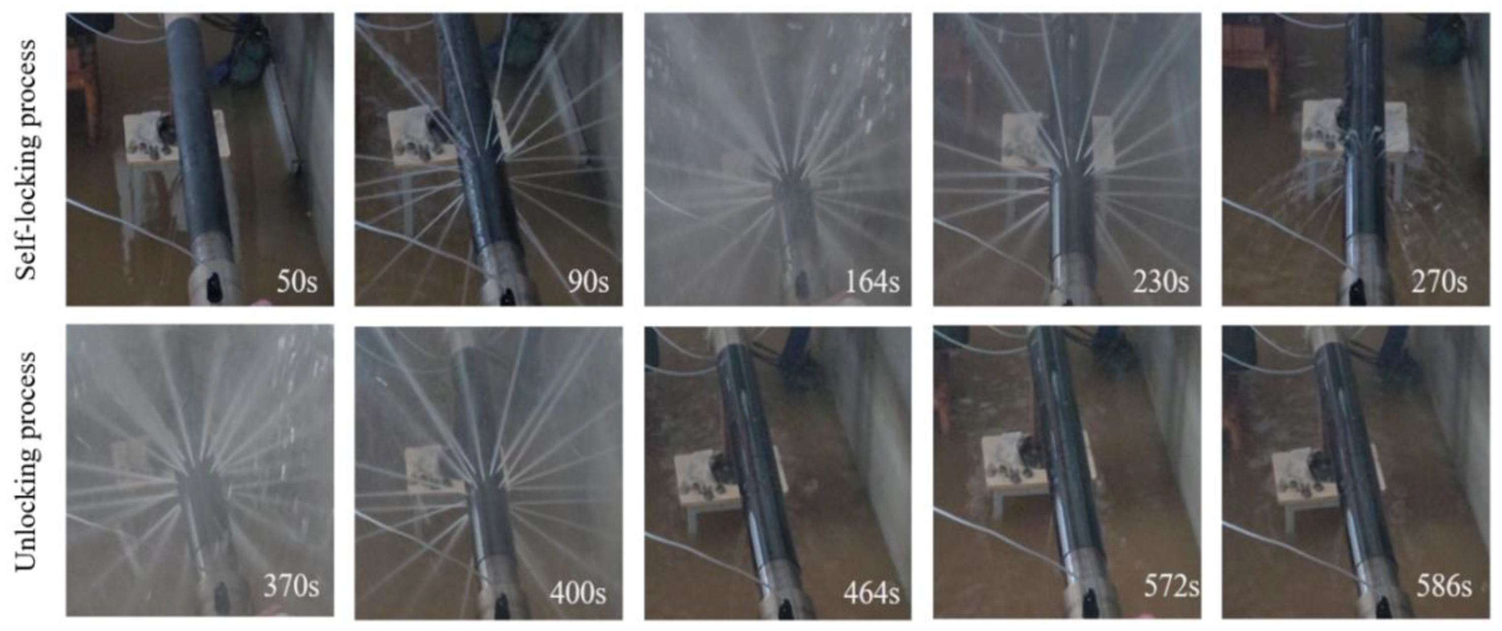
As shown in Figure 19, when the inlet drilling fluid flow rate gradually increased from 0 to 470 L/min, the number of nozzles opened on the PJCT gradually increased and the sliding core was moving axially to the predetermined position. When the fluid flow rate reached 453 L/min, the experimental phenomena showed that the jet nozzle was fully opened, as shown in Figure 20 at 164 s, the drilling fluid flow rate at the outlet of the PJCT suddenly decreased to 0 L/min, and the inlet pressure value increased from 0.25 MPa to 0.908 MPa, which shows that the sliding core has moved to the maximum axial position. Then the drilling fluid flow rate gradually reduced to 0 L/min. After that, the drilling fluid flow gradually increased to 470 L/min again. During this process, the nozzle was fully opened, as shown in Figure 20 at 370 s, which indicates that the tool is in a self-locking state. When the flow rate increased to 275 L/min and the maximum inlet pressure reached 0.945 MPa, the experimental phenomenon showed that the spray intensity of the nozzles and the number of open nozzles gradually decreased, as shown in Figure 20 at 572 s, which indicates that the sliding core is unlocked. Finally, when the flow rate was reduced to 0 L/min and loaded to 300 L/min again, the drilling fluid was not ejected from the jet nozzle. At the same time, Figure 19 shows that the outlet flow and inlet flow of the PJCT were consistent after 450 s, which verifies that the sliding core has completed unlocking and has returned to original state.

6. Conclusions and Discussion

Aimed at the demand for jet crushing in the solid fluidization exploitation method of NGH and the shortcomings of the jet crushing tool in the first global solid fluidization test production process, this paper presented an innovative PJCT with a self-locking function based on the principle of throttling pressure control. The PJCT’s sliding core dynamic simulation model was established by the multi-body dynamics simulation software. Then the multi-body dynamics simulation revealed the displacement law and velocity law of the sliding core under the influence of different factors. Finally, the prototype of the PJCT was machined, the experimental platform was set up to carry out the prototype verification experiment.
The following conclusions were obtained:
(1)
As the flow rate of drilling fluid increased, the time from fluctuating to stable for the sliding core was almost unchanged under the same spring stiffness, which indicated that the stability time of the sliding core fluctuation was independent of the drilling fluid flow level. As the spring stiffness increased, the fluctuation range of the sliding core was also smaller, but the time for the sliding core to stabilize increased at the same flow rate, which indicated that the stability of the sliding core decreases.
(2)
As the friction coefficient between the parts increased, the fluctuation range of the velocity and displacement of the sliding core became smaller under the same flow rate and spring stiffness. Therefore, the recommendation for the selection of the sliding core material is that the friction between the sliding core and the remaining parts should be controlled while ensuring the rapid response of the sliding core.
(3)
The verification experiment showed that the PJCT would not open the jet nozzle under a normal drilling flow of 300 L/min. When the drilling fluid flow reached 455 L/min or the inlet pressure drop reached about 0.9 MPa, the PJCT could stably complete the self-locking and unlocking functions and the self-locking mechanism had the prospect of application to other down hole tools for oil and gas exploitation.
(4)
In future research, a kind of PJCT with a suction port will be proposed. This type of PJCT jet crushing-propeller recovery model will be established by analyzing the relationship between the nozzle installation position and the suction port, which can provide a theoretical basis for advancing the solid-state fluidized exploitation of natural gas hydrates.

Author Contributions

Y.T. and P.Z. designed the simulation model, carried out the simulation of the proposed model, carried out the experiments, analyzed the data, and wrote the initial draft of the manuscript; X.L. and X.F. conceived and designed the experiments; P.Y. reviewed and contributed to the final manuscript. All authors have read and agreed to the published version of the manuscript.

Funding

This work is supported by the National Natural Science Foundation of China (grant numbers 52004235); National Key Research and Development Program (grant numbers 2021YFC2800903); International Science and Technology Cooperation Project Funding (grant numbers 2020-GH02-00041-HZ); China Postdoctoral Science Foundation (grant numbers 2020M683359); National Science and Technology Major Project (grant numbers 2016ZX05028-001-006); China Postdoctoral Innovative Talents Support Program (grant numbers BX20190292); Sichuan Province Applied Basic Research Project (grant numbers 2020YJ0152); the Miaozi Engineering Project of Sichuan Science and Technology Department (No. 2021124); and the Fund of Southern Marine Science and Engineering Guangdong Laboratory (Zhanjiang) (grant numbers ZJW-2019-03).

Institutional Review Board Statement

Not applicable.

Informed Consent Statement

Not applicable.

Data Availability Statement

All data and models generated or used during the study appear in the submitted article.

Conflicts of Interest

The authors declare no conflict of interest.

References

  1. Zhou, S.W.; Li, Q.P.; Lv, X.; Fu, Q.; Zhu, J.L. Key issues in development of offshore natural gas hydrate. Front. Energy 2020, 14, 433–442. [Google Scholar] [CrossRef]
  2. Pinkert, S. Dilation behavior of gas-saturated methane-hydrate bearing sand. Energies 2019, 12, 2937. [Google Scholar] [CrossRef] [Green Version]
  3. Sloan, E.D. Fundamental principles and applications of natural gas hydrates. Nature 2003, 426, 353–359. [Google Scholar] [CrossRef]
  4. Makogon, Y.F. Natural gas hydrates–A promising source of energy. J. Nat. Gas Sci. Eng. 2010, 2, 49–59. [Google Scholar] [CrossRef]
  5. Wang, G.R.; Zhong, L.; Zhou, S.W.; Liu, Q.; Li, Q.; Fu, Q.; Huang, R. Jet breaking tools for natural gas hydrate exploitation and their support technologies. Nat. Gas Ind. 2018, 5, 312–318. [Google Scholar] [CrossRef]
  6. Fitzgerald, G.C.; Castaldi, M.J.; Zhou, Y. Large scale reactor details and results for the formation and decomposition of methane hydrates via thermal stimulation dissociation. J. Pet. Sci. Eng. 2012, 94, 19–27. [Google Scholar] [CrossRef]
  7. Ota, M.; Abe, Y.; Watanabe, M. Methane recovery from methane hydrate using pressurized CO2. Fluid Phase Equilib. 2005, 228, 553–559. [Google Scholar] [CrossRef]
  8. Aghajari, H.; Moghaddam, M.H.; Zallaghi, M. Study of effective parameters for enhancement of methane gas production from natural gas hydrate reservoirs. Green Energy Environ. 2019, 4, 453–469. [Google Scholar] [CrossRef]
  9. Giraldo, C.; Klump, J.; Clarke, M. Sensitivity analysis of parameters governing the recovery of methane from natural gas hydrate reservoirs. Energies 2014, 7, 2148–2176. [Google Scholar] [CrossRef] [Green Version]
  10. Qorbani, K.; Kvamme, B.; Kuznetsova, T. Using a reactive transport simulator to simulate CH4 production from bear island basin in the Barents Sea utilizing the depressurization method. Energies 2017, 10, 187. [Google Scholar] [CrossRef] [Green Version]
  11. Chen, C.; Pan, D.; Yang, L.; Zhang, H.; Li, B.; Jin, C.; Zhong, X. Investigation into the water jet erosion efficiency of hydrate-bearing sediments based on the arbitrary Lagrangian-Eulerian method. Appl. Sci. 2019, 9, 182. [Google Scholar] [CrossRef] [Green Version]
  12. Zhou, S.W.; Zhao, J.; Li, Q.Y.; Chen, W.; Zhou, J.; Wei, N.; Sun, W. Optimal design of the engineering parameters for the first global trial production of marine natural gas hydrates through solid fluidization. Nat. Gas Ind. 2018, 5, 118–131. [Google Scholar] [CrossRef]
  13. Zhou, S.W.; Chen, W.; Li, Q.P. The green solid fluidization development principle of natural gas hydrate stored in shallow layers of deep water. China Offshore Oil Gas 2014, 26, 1–7. [Google Scholar]
  14. Wei, N.; Sun, W.; Meng, Y.; Liu, A.; Zhao, J.; Zhou, S.W.; Li, Q.Y. Multiphase non equilibrium pipe flow behaviors in the solid fluidization exploitation of marine natural gas hydrate reservoir. Energy Sci. Eng. 2018, 6, 760–782. [Google Scholar] [CrossRef] [Green Version]
  15. Tang, Y.; Yao, J.X.; Wang, G.R.; Lin, Z.; He, Y.F.; Liu, Q.Y. Development and laboratory experiments of pressure-controlled sliding sleeves for injection and crushing operations in the exploitation of deep sea shallow non diagenetic marine gas hydrates. Nat. Gas Ind. 2020, 40, 186–194. [Google Scholar]
  16. Tang, Y.; Yao, J.X.; He, Y.; Sun, P.; Jing, X. Study on pressure-controlled sliding sleeve of jet breaking for natural gas hydrate mining based on throttle pressure drop principle. Energy Sci. Eng. 2020, 8, 1422–1437. [Google Scholar] [CrossRef]
  17. Tang, Y.; Huang, S.X.; Yao, J.X.; Liu, Q.Y.; Wang, G.R.; Zhou, S.W. An Automatic Jet Breaking Tool for Solid-State Fluidized Exploitation of Natural Gas Hydrate. CN Patent Application No. CN110700801A, 17 January 2020. [Google Scholar]
  18. Zou, L.; Hu, G.Z.; Wen, H.B.; Xu, X.J.; Pu, F. Effect of Spring Stiffness Coefficient on the Performance of One Way Valve Closed. Fluid Mach. 2017, 45, 47–51. [Google Scholar]
  19. Klas, R.; Habán, V.; Rudolf, P. Analysis of in-line check valve with respect to the pipeline dynamics. Eur. Phys. J. Conf. 2017, 143, 02051. [Google Scholar] [CrossRef]
  20. Wang, J.Z.; Chen, E.F.; Yu, W.J.; Ye, C.; Song, B.F. Mechanism of self-excited vibration and dynamic stability for pneumatic valves. J. Aerosp. Power 2014, 9, 1490–1497. [Google Scholar]
  21. Li, Y.; Jiao, Z.; Wu, S. Flow characteristics analysis and optimization design of high frequency reciprocation pump applying check valve to rectification. J. Mech. Eng. 2013, 49, 154–163. [Google Scholar] [CrossRef]
  22. Lai, Z.; Karney, B.; Yang, S.; Wu, D.; Zhang, F. Transient performance of a dual disc check valve during the opening period. Ann. Nucl. Energy 2017, 1, 15–22. [Google Scholar] [CrossRef]
  23. Xiang, B.P.; Yin, G.F.; Zeng, X.W.; Zang, H.B. Research on Open and Close Characteristics of Passive Shuttle-type Anti-water-attack Check Valve. Key Eng. Mater. 2011, 474, 2290–2295. [Google Scholar] [CrossRef]
  24. Lee, T.S.; Low, H.T.; Nguyen, D.T.; Neo, W.R.A. Experimental study of check valves performances in fluid transient. Proc. Inst. Mech. Eng. Part E J. Process Mech. Eng. 2009, 223, 61–69. [Google Scholar] [CrossRef]
  25. Mo, N. Engineering Fluid Mechanics; Huazhong University of Science and Technology Press: Wuhan, China, 2009; pp. 145–147. [Google Scholar]
  26. Xie, Z. Engineering Fluid Mechanics, 4th ed.; Metallurgical Industry Press: Beijing, China, 2013; pp. 135–138. [Google Scholar]
Figure 1. Solid fluidization exploitation of NGH.
Processes 10 01033 g001
Figure 2. Structure diagram of PJCT: (a) PJCT in closed state, (b) PJCT in opend state.
Processes 10 01033 g002
Figure 4. Dynamic simulation model of PJCT.
Processes 10 01033 g004
Figure 5. The sliding core movement displacement changes with spring stiffness and drilling fluid flow: (a) Spring stiffness 2 N/mm; (b) Spring stiffness 2.5 N/mm; (c) Spring stiffness 3.0 N/mm; (d) Spring stiffness 3.5 N/mm.
Processes 10 01033 g005
Figure 6. The sliding core movement velocity changes with spring stiffness and drilling fluid flow: (a) Spring stiffness 2 N/mm; (b) Spring stiffness 2.5 N/mm; (c) Spring stiffness 3.0 N/mm; (d) Spring stiffness 3.5 N/mm.
Processes 10 01033 g006
Figure 7. The sliding core movement displacement changes with friction coefficient.
Processes 10 01033 g007
Figure 8. The sliding core velocity laws changes with friction coefficient.
Processes 10 01033 g008
Figure 9. Five different flow loading schemes.
Processes 10 01033 g009
Figure 10. The rotation angle changes with different flow loading schemes.
Processes 10 01033 g010
Figure 11. Experimental prototype of PJCT. (a) Parts of PJCT; (b) Overall Structure of PJCT Test Prototype.
Processes 10 01033 g011
Figure 12. Experimental equipment.
Processes 10 01033 g012
Figure 13. Schematic diagram of experimental principle.
Processes 10 01033 g013
Figure 14. Drilling fluid flow and pressure of Experiment I change with time.
Processes 10 01033 g014
Figure 15. Experimental phenomena of experiment I: (a) Experimental phenomenon at 25 s; (b) Experimental phenomenon at 75 s; (c) Experimental phenomenon at 114 s.
Processes 10 01033 g015
Figure 16. Drilling fluid flow and pressure of Experiment II and Experiment III changed with time.
Processes 10 01033 g016
Figure 17. Outlet fluid flow rate and pressure of Experiment II and Experiment III changed with time.
Processes 10 01033 g017
Figure 18. Experimental phenomena of Experiment II and Experiment III.
Processes 10 01033 g018
Figure 19. Drilling fluid flow and pressure of Experiment IV change with time.
Processes 10 01033 g019
Figure 20. Experimental phenomena of Experiment IV.
Processes 10 01033 g020
Table 1. The contact of each component and the corresponding constraint pair settings.
Constraint Vice
Name
Parts NameContact NameParts Name
Cylindrical pairSlide core, lock sleeveContact 1Slide core, lock sleeve
Sliding pairSlide core, upper jointContact 2Upper joint, lock sleeve
Cylindrical pairLock sleeve, upper jointContact 3Slide core, lower joint
Fixed pairUpper jointContact 4Upper joint, Slide core
Fixed pairLower jointContact 5Lower joint, lock sleeve
Table 2. Four groups flow loading schemes.
Experiment NumberFlow Loading Scheme (L/min)Experiment Purpose
I0~300Verify whether the jet nozzle is opened during normal drilling
II0~470~0~100~0Verify whether the PJCT is fully opened and self-locked at 470 L/min
III0~470~0Verify whether the PJCT can be unlocked at 470 L/min
IV0~470~0~470~0~300~0Verify whether the PJCT can complete self-locking and unlocking in a continuous cycle
Publisher’s Note: MDPI stays neutral with regard to jurisdictional claims in published maps and institutional affiliations.