Article

A Case Study on Surrounding Rock Deformation Control Technology of Gob-Side Coal-Rock Roadway in Inclined Coal Seam of a Mine in Guizhou, China

1
College of Mining, Guizhou University, Guiyang 550025, China
2
Coal Mine Roadway Support and Disaster Prevention Engineering Research Center, Beijing 100083, China
3
National & Local Joint Laboratory of Engineering for Effective Utilization of Regional Mineral Resources from Karst Areas, Guiyang 550025, China
4
Key Laboratory of Mining Disaster Prevention and Control, Qingdao 266590, China
*
Author to whom correspondence should be addressed.
Processes 2022, 10(5), 863; https://doi.org/10.3390/pr10050863
Submission received: 5 April 2022 / Revised: 23 April 2022 / Accepted: 25 April 2022 / Published: 27 April 2022
(This article belongs to the Section Energy Systems)

Abstract

:
Surrounding rock deformation control of gob-side coal-rock roadway in inclined coal seams (GCRICS) is a major problem in gob-side entry technology application practice. This paper describes a case study of the surrounding rock deformation characteristics and control technology of a typical GCRICS in Guizhou, China. As according to data obtained during a field investigation, the reasons for the deformation and failure of 151509 tailentry and the shortcomings of the original support scheme were analyzed. In combination with existing theory and field experience, the “anchor cable + U-shaped steel + shotcreting + grouting” (CUSG) support method was proposed. The plastic zone distribution, displacement, and stress evolution law of the roadway-surrounding rock under the four support modes were analyzed and compared by numerical simulation. The results show that the supporting effects of several support methods varied from good to poor; CUSG was the best, followed by anchor cable support, U-shaped steel support, and then no support. Based on the previous seepage grouting theory, a slurry diffusion model of hollow grouted anchor cable (HGC) was established and the calculation formulas of slurry diffusion radius and grouting time were deduced, which provided guidance for field construction. Finally, the CUSG surrounding rock control technology was applied to 151509 tailentry subsequent roadway support. Through drill holes, analysis of the surrounding rock of the non-grouting area and the grouting area was conducted. It was found that the surrounding rock of the grouting area was high in integrity and strong in bearing capacity. Throughout the excavation period to the end of roadway mining, the roadway did not have to be repaired. This case study has high practicability, high popularization value, and provides a useful reference for the engineering support design of the GCRICS.

1. Introduction

In recent years, gob-side entry driving (GED) technology has rapidly developed due to the obvious advantages in reducing coal loss, improving coal recovery ratio, and prolonging mine service life [1,2,3,4,5,6,7,8,9]. At the same time, scholars have also performed unremitting exploration and practice in the areas of deformation, failure mechanisms, and control technology of surrounding rock in gob-side entry driving and have made many achievements.
Shi et al. [10] studied the movement law, failure mechanism and fracture evolution of overlying strata in GED in a thick coal seam using a physical model test and numerical simulation; they found that roof cutting and pressure releasing can release the overlying load and improve surrounding rock stability. Hou et al. [11] proposed the stability principles of large and small structures of surrounding rock in GED. Han et al. [12] found that the dynamic load generated by the fracture of the overlying rock was the main cause of the dynamic behavior in the gob-side roadway. Zhang et al. [13] proposed a new method based on the unique characteristics of rolling accumulation of gangue in the goaf of a steeply inclined coal seam. Wang et al. [14] considered that controlling the rotational instability of key blocks was a prerequisite for maintaining the overall stability of the roadway on the basis of establishing a structural mechanics model. Wu et al. [15] studied the surrounding rock characteristics of gob-side entry retaining (GER) under different layout conditions using cutting line of prefabricated roof and put forward the optimal layout scheme of cutting line in GER with roof cutting and pressure relief. Wang et al. [16] found that the vertical stress of the sides was the main factor of floor heave in gob-side entry and proposed a layout of staggered negative coal pillars along the gob-side entry to control floor heave by reducing the sides’ vertical stress. Bai et al. [17] proposed the surrounding rock control mechanism of GED in fully mechanized caving by analyzing the stability of the basic top arc triangle block. Qin et al. [18] studied the development law of mining pressure along GER in deep thin coal seam mining. Basarir et al. [19] analyzed the stress magnitude and direction of stresses around the gob-side entry using a three-dimensional finite difference technique. Jiang et al. [20] calculated and analyzed the rock structure characteristics and internal stress field distribution of gob-side entry based on elastic foundation beam theory, internal stress field theory, and external stress field theory. Additionally, they systematically studied the influence of rock structure and coal pillar width on the deformation mechanism of gob-side entry during excavation. Wilson [21] pointed out that there exists a failed or yielded zone and an elastic zone in the pillar and a goaf region with stress increasing linearly. Shabanimashcool et al. [22] found that the stability of the roadway near the goaf and the load of the bolt are closely related to the width of coal through numerical simulation. Zhao et al. [23] established a mechanical model of surrounding rock structure in GED and through solving the equation and analyzing the law, the deformation control mechanism of surrounding rock in GED was revealed. Arthur et al. [24] used multiple regression and numerical simulation to establish the relationship between the deformation of rock mass and the strength of the coal pillar by studying the different pillars’ shape and size, which provided a reference for the reasonable width of a coal pillar in gob-side entry. Zheng et al. [25] analyzed the dynamic evolution process of the lateral abutment pressure of an in-situ coal pillar under the influence of primary mining, established the mechanical model with limited deformation, calculated the reasonable width, put forward the supporting principle of structural coordination, and determined the coordinated surrounding rock control technology with the anchor beam cable acting as the basic support and the π-type steel beam single pillar as the strengthening support. Tian et al. [26] proposed a surrounding rock stability control technology consisting of roadway with a soft roof and a floor in a thin coal seam, according to the difficulties and key points of surrounding rock control. Zhang et al. [27] studied the mechanism of pre-splitting and pressure relief on the roof of goaf and proposed a structural control principle consisting of GER with overall reinforcement. He et al. [28] pointed out that the inclined extrusion pressure between the basic roof and the immediate roof is the essential reason for the horizontal movement and asymmetric failure of the roof on the GED, and based on the mechanical model of the direct roof considering the inclined extrusion pressure, a systematic asymmetric support theory was proposed. Peng et al. [29] proposed a support scheme consisting of “anchor, mesh, and spray + grouting + full-section anchor cable + floor anchor cable”, and through numerical simulation and field verification, this method could effectively complete the safety control of the roadway. Wang et al. [30] proposed a new type of combined support technology, including advanced grouting, grouting bolts, and grouting anchor cables according to the support principles of grouting reinforcement, pre-reinforced support, and rational support range.
The above research results and theories have been utilized in comprehensive and in-depth studies on the deformation mechanism, failure mechanism, and control technology of surrounding rock in gob-side entry, but most of them are for GED in near-horizontal thick coal seam.
However, the distribution of coal resources in China is significantly different [31,32]. Compared to the north, the coal resources in various provinces and cities in the south are scarce, and the conditions of the coal reserves are complex [33], which are mainly inclined thin and medium thick coal seams, resulting in a wide distribution of coal-rock roadways in inclined coal seams. At the same time, in order to reduce the waste of coal resources, major mining areas in the south have begun to apply gob-side entry technology to improve coal recovery ratio. However, due to the influence of dynamic pressure on GCRICS, heterogeneity and asymmetry of the surrounding rock structure, the high degree of fragmentation, and the low mechanical strength [34], large deformation often occurs in the roadway during excavation and mining. These result in support failure and roadway instability, which greatly increases the maintenance cost of the roadway. Based on the engineering background of 151509 gob-side coal-rock tailentry in a mine in Guizhou Province, China, the surrounding rock control technology of GCRICS was proposed and verified through numerical simulation, theoretical analysis, and field detection, and then successfully applied in the field. It has important scientific significance and engineering application value for improving the surrounding rock control technology of gob-side coal-rock roadway (GCR), ensuring the efficient mining of GCR in southern China, and improving the economic benefits of coal mining enterprises.

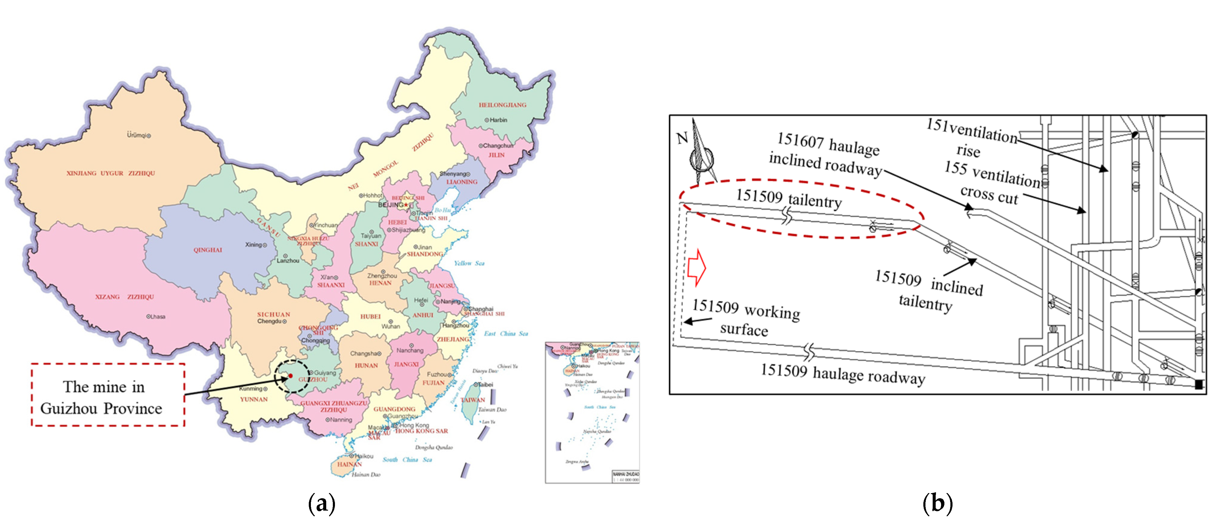
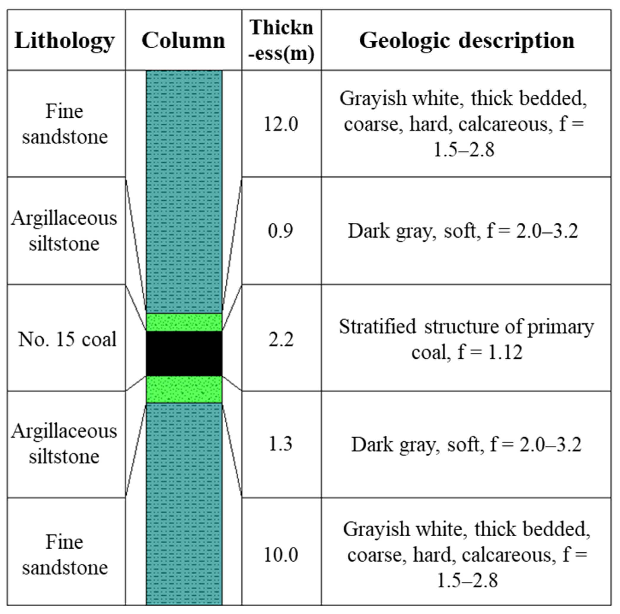
2. Engineering Background

2.1. Overview of the Mine

A mine in Guizhou Province is located in Liupanshui City, Guizhou Province, China (Figure 1a). The 151509 working faces of the mine adopt the strike long-wall double-wing layout mining method. The main roadway layout is shown in Figure 1b. The working face is 613 m in strike length and it is 125 m in inclined length. Mining occurs along the No. 15 coal seam. The elevation difference between the working face and the surface is ~556–564 m. The strike of coal seam is ~93–107°, the inclination is ~183–197°, and the dip angle is ~19–23°, generally 20°. The thickness of the coal on the working face is ~1.4–3 m, with an average of 2.2 m. The hardness is f = 1.12. The detailed strata histogram is illustrated in Figure 2. The 151509 tailentry are designed of 5 m wide coal pillar to protect the roadway, which is a typical GCRICS.

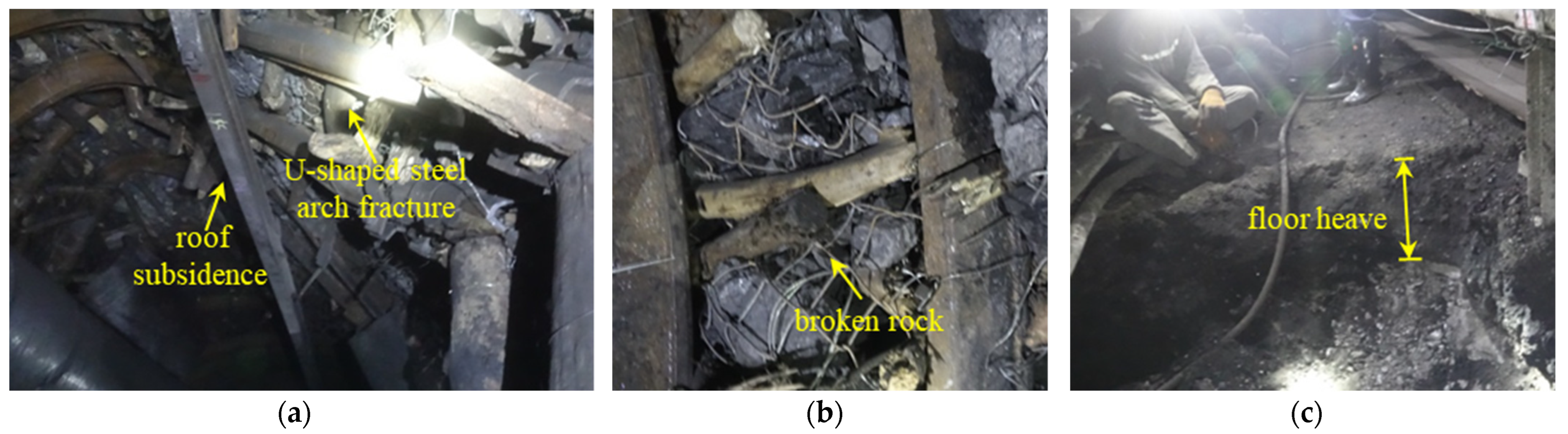
2.2. Deformation Characteristics of Roadway under Original Support Scheme

The initial excavation stage of 151509 tailentry used 29 U-shaped steel supports; due to the limitations of the support method, the roadway was seriously damaged. Repair schemes, such as brickwork reinforcement and strengthening support of timber pillars in the middle line of the roof, were successfully adopted, but the control effect was not ideal: the surrounding rock still presents a trend of large deformation and the roadway section continues to shrink. This not only increases mine ventilation resistance, but also seriously affects pedestrian safety and the normal production of the mine. Effective repair of the roadway was extremely urgent. According to the field investigation and the data provided by the mine, the deformation and failure characteristics of the roadway were mainly as follows:
(1)
Roof subsidence and support failure
The overlying rock structure of the roadway roof was mainly composed of argillaceous siltstone. This kind of rock is rich in bedding, low in strength, fast in weathering, easy to slime in contact with water, and poor in self-stability. In addition, the mining depth was high, which resulted in roof subsidence due to high crustal stress. Furthermore, the strength of the original U-shaped steel support was low and could not support roof subsidence, which lead to the failure of some support sections. (Figure 3a).
(2)
Broken sillar falling
The roadway surrounding rocks were soft and broken. After roadway excavation, broken rocks (Figure 3b) are subject to gravity and squeezing between sillars, resulting in their falls. The U-shaped steel supports used in the field cannot create a large range of control on surrounding rock; therefore, the interactions between sillars changes, resulting in the redistribution of surrounding rock stress, causing multiple disturbances to the roadway and threatening the safety of workers and influencing the smooth progress of mining.
(3)
Serious floor heave
Since the floor was not subjected to supporting measures and it was mainly composed of argillaceous siltstone with low strength, the stress of roof and side was transferred to the floor, and was released in the weakest part, resulting in floor heave (Figure 3c). This caused the contraction of roadway section, change of ground equipment position, and affected the normal operation of equipment.
The original support was not only unable to control the deformation of the roadway, but also increased the workload of roadway repair. There were more than 800 professional roadway repairmen in the whole mine. The input of roadway repair materials was also greater than the cost of mining and driving. At the same time, due to the large intensity of roadway repair and the imperfect repair technology, repeated repair will lead to industrial accidents that seriously restrict the high-quality development of the mine. Therefore, it is urgent to find an economic and effective support method to control roadway deformation and ensure the subsequent safe and efficient mining of the mine.

3. CUSG Support Method

3.1. Selection of Support Method

The existing support methods for controlling roadway deformation are divided into three categories: active support, passive support, and combined support. Active supports include bolts, anchor cables, grouting reinforcement, etc. [35,36,37,38,39]. Passive supports include U-shaped steel supports, brickwork, shed supports, single pillar, etc. The original passive support with U-shaped steel can only implement passive support on the surface of the roadway and cannot be coupled with overlying strata as the overall bearing structure. When the overlying strata are affected by disturbance pressure, the internal stress of the surrounding rock is no longer balanced and redistributed, and the surrounding rock of roadway is broken, U-shaped steel supports cannot effectively control the movement of deep surrounding rock and the leakage of broken rock mass, resulting in support failure. If the bolt (anchor cable) active support is adopted, the mechanical properties of the surrounding rock and the stress distribution state of the deep surrounding rock can be improved by applying prestress, so that the sillar in the anchorage zone squeeze each other to form the overall anchorage structure and improve the stability of rock strata. However, due to the high degree of rock fragmentation, the fracture of broken rock mass is relatively rich and connected, and the weak surface interaction force between sillar is small, which cannot support the self-weight of sillar, so that the anchoring effect of the bolt (anchor cable) on the upper rock strata is greatly reduced. This results in failure to form the overall bearing structure range or its narrowing, reducing the supporting effect. Therefore, for the roadway with extremely broken surrounding rock, using only bolt (anchor cable) anchorage to improve the stability of the upper rock mass cannot meet the support requirements. A large number of studies have shown that grouting reinforcement can make slurry penetrate, fill, and close the cracks of the surrounding rock; reduce the porosity of surrounding rock; improve the integrity, stress state, self-supporting ability, and stability of fractured surrounding rock; and increase the strength of the surrounding rock [40,41,42,43,44,45]. Based on the above analysis, single active support and passive support cannot reasonably and effectively control the surrounding rock deformation of such GCRICS. Therefore, a combined support method of “anchor cable + U-shaped steel + shotcreting + grouting” (CUSG) was proposed, and its supporting effect was to be investigated.

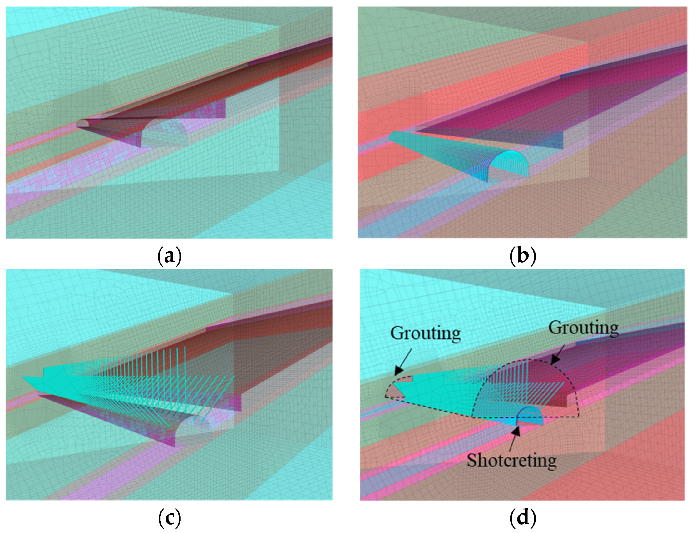
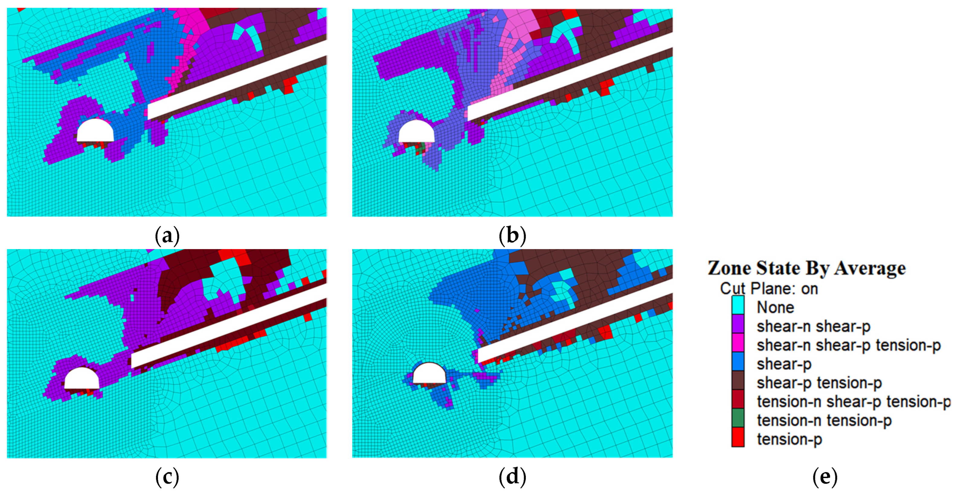
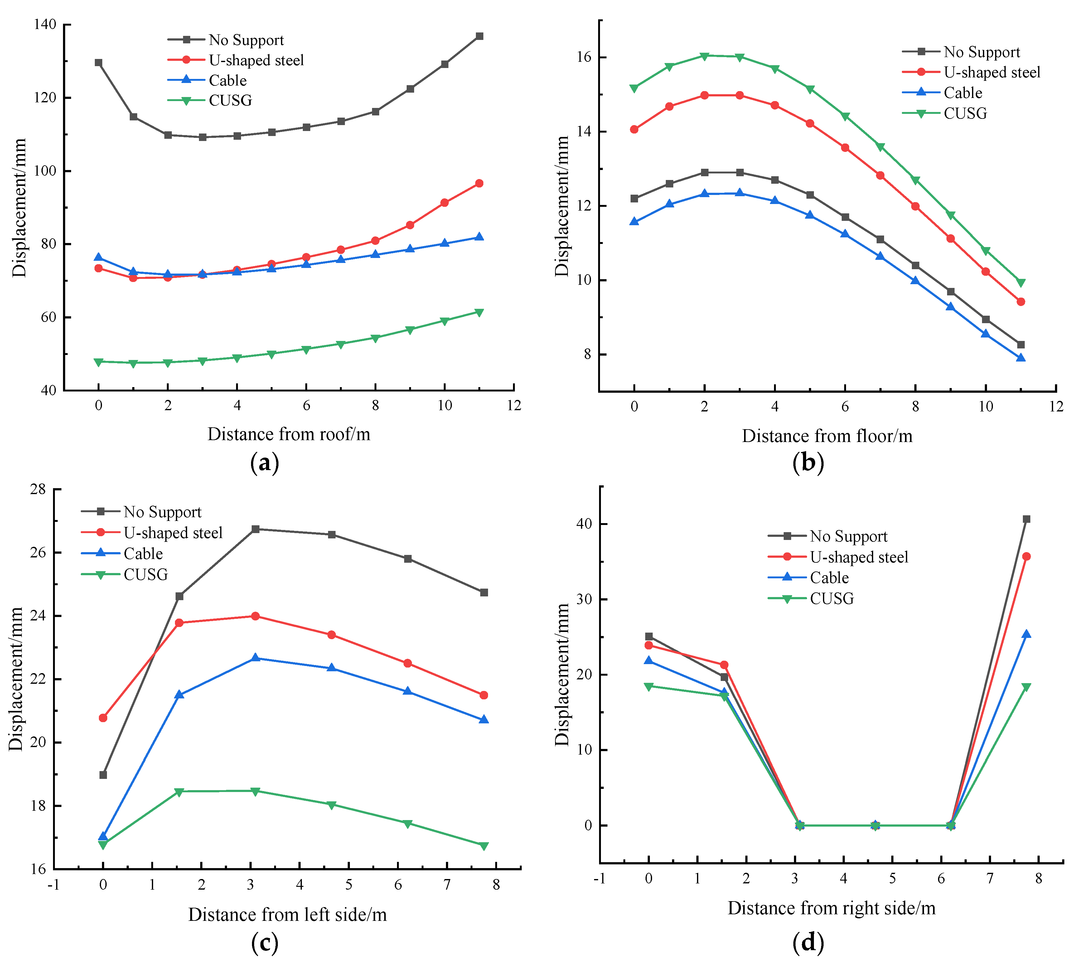
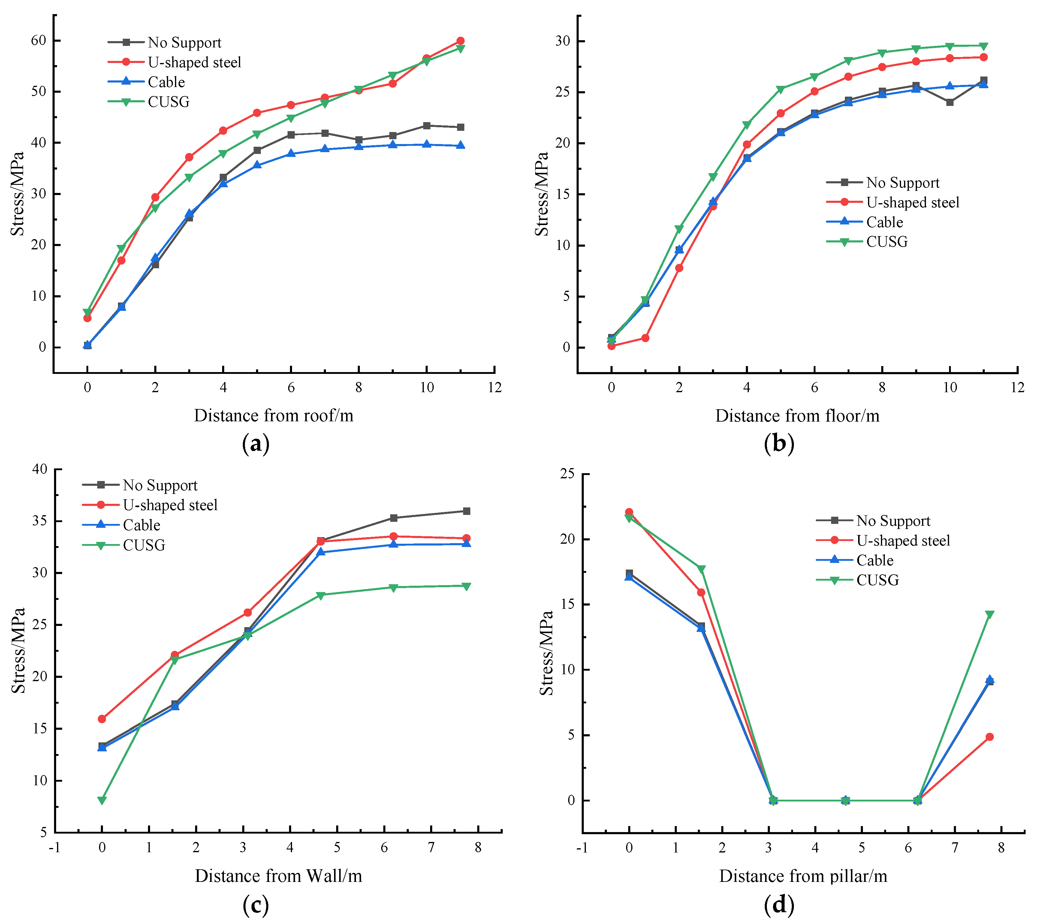
3.2. Numerical Simulation

To verify the rationality of CUSG support method, a numerical model was established, as shown in Figure 4. The numerical model had dimensions of 150 m (X) × 100 m (Y) × 80 m (Z). As the research focuses mainly on the roof and floor of the roadway and its surrounding rock, taking into account the speed of computer operation, a 10 m grid of surrounding rock around the roadway was encrypted. The bottom of the model was fixed, the horizontal displacement around was restricted, a vertical stress of 12.75 MPa was applied to the upper boundary to simulate the overburden stress, the constitutive relation of surrounding rock using Mohr–Coulumb model, and four measuring lines were arranged in the roof and floor of the roadway and its two sides to continuously monitor the stress and strain of the surrounding rock. Simulations of the roadway surrounding rock deformation under no support, U-shaped steel support, anchor cable support and CUSG support (Figure 5) were performed. The indoor rock mechanics experiment was carried out after field sampling. At the same time, combined with the test results of the relevant mechanical parameters of coal and rock stratum given in the exploration report of the mine and other geological data, the Hoek–Brown strength criterion based on the geological strength index (GSI) and rock mass rating (RMR) was comprehensively considered to correct the rock mechanics parameters, and the physical and mechanical parameters of coal and rock stratum in the mine were obtained. The specific parameters are shown in Table 1 and Table 2.

3.3. Analysis of Numerical Simulation Results

The plastic zone is an important index to evaluate the stability of roadway surrounding rock. The plastic zone distribution slice of roadway surrounding rock at the center of the model (Y = 50 m) under four support methods was intercepted, as shown in Figure 6. The analysis shows that: (1) Under the former three supporting methods, the plastic zone of surrounding rock was connected to the plastic zone formed at the gob side after the mining of the upper section working face through the coal pillar. Since the gob is formed by the mining of the upper section of the working face, the key block of the main roof produces rotary subsidence at the boundary of the coal pillar near the gob, and the main roof above the coal pillar does not produce rotary deformation, resulting in the extension trend of the plastic zone in the gob of the upper section working face bypass above the coal pillar to the top of the roadway, and an “inverted C” type of undamaged zone is formed above the coal pillar. Under CUSG support, the surrounding rock and the coal pillar change their mechanical properties by grouting. The overall bearing structure is formed from deep below to the surface of the roadway, which improves the bearing capacity of the surrounding rock and makes the plastic zone almost not appear above the roadway and even on the coal pillar. (2) Under the no support and anchor cable support conditions, the plastic zone of the solid coal side was larger than that of the other two kinds of support, indicating that due to the extremely broken surrounding rock, the anchor cable could not be fully prestressed from the surrounding rock, resulting in invalid anchoring. Under the U-shaped steel support and CUSG support conditions, the plastic zone at the bottom of the roadway was larger, indicating that the two methods had higher support strength for the surrounding rock. This results in the surrounding rock being only able to release pressure in the weak support area (floor), resulting in a large range of floor damage. (3) The distribution ranges of the plastic zone of the surrounding rock of the roadway roof under the four supporting methods, from largest to smallest, were no support, U-shaped steel, anchor cable, and CUSG.
According to the displacement evolution curve of the roadway roof and floor and two sides under different supporting methods (Figure 7), the following conclusions can be made: (1) Under the support of CUSG, the deformation of roof and two sides was smaller than the other supporting methods; only the range of floor heave was larger than other methods. These is in good agreement with the distribution of the plastic zone. (2) The deformation of the roof, coal pillar, and coal wall without support was larger than that with support. This shows that U-shaped steel and anchor cable support have some control effects on these parts. (3) The displacement of surrounding rock within 2 m from the top of roadway under U-shaped steel support was smaller than that under anchor cable support, and the deformation at other positions was greater than that under anchor cable support. Based on the analysis of the deformation evolution laws of the roof and floor and the two sides, the deformation degrees under the four support modes from largest to smallest were no support, U-shaped steel support, anchor cable support and CUSG support.
In order to reveal the stress distribution and evolution law of the roadway surrounding rock under the four supporting methods, the stress data of four measuring lines in the roof and floor, the side near the coal wall and the side near the coal pillar were extracted for analysis (Figure 8). Based on the principle that the stronger the bearing capacity of coal and rock mass, the higher the accumulated stress inside of it is [46], the following conclusions were obtained: (1) Under the four supporting methods, the greater the degree of entry into the deep area of the surrounding rock, the stronger the bearing capacity of the coal and rock mass at the roof and floor and the side near the solid coal. The closer the supporting range, the stronger the bearing capacity of the side near the coal pillar was. (2) After using CUSG support, the bearing capacity of the roof and coal pillars was higher than other support methods. In the roof, the bearing capacity of surrounding rock was only lower than that of U-steel support in the range of 2–7 m from the surface of the roadway, while in the side near the coal wall, the bearing capacity of the surrounding rock under CUSG support was generally low.
Based on the above plastic zone distribution, displacement, and stress evolution law, it can be comprehensively concluded that the support effect of the four support methods ordered from best to worst is CUSG, anchor cable, U-shaped steel, and then no support.

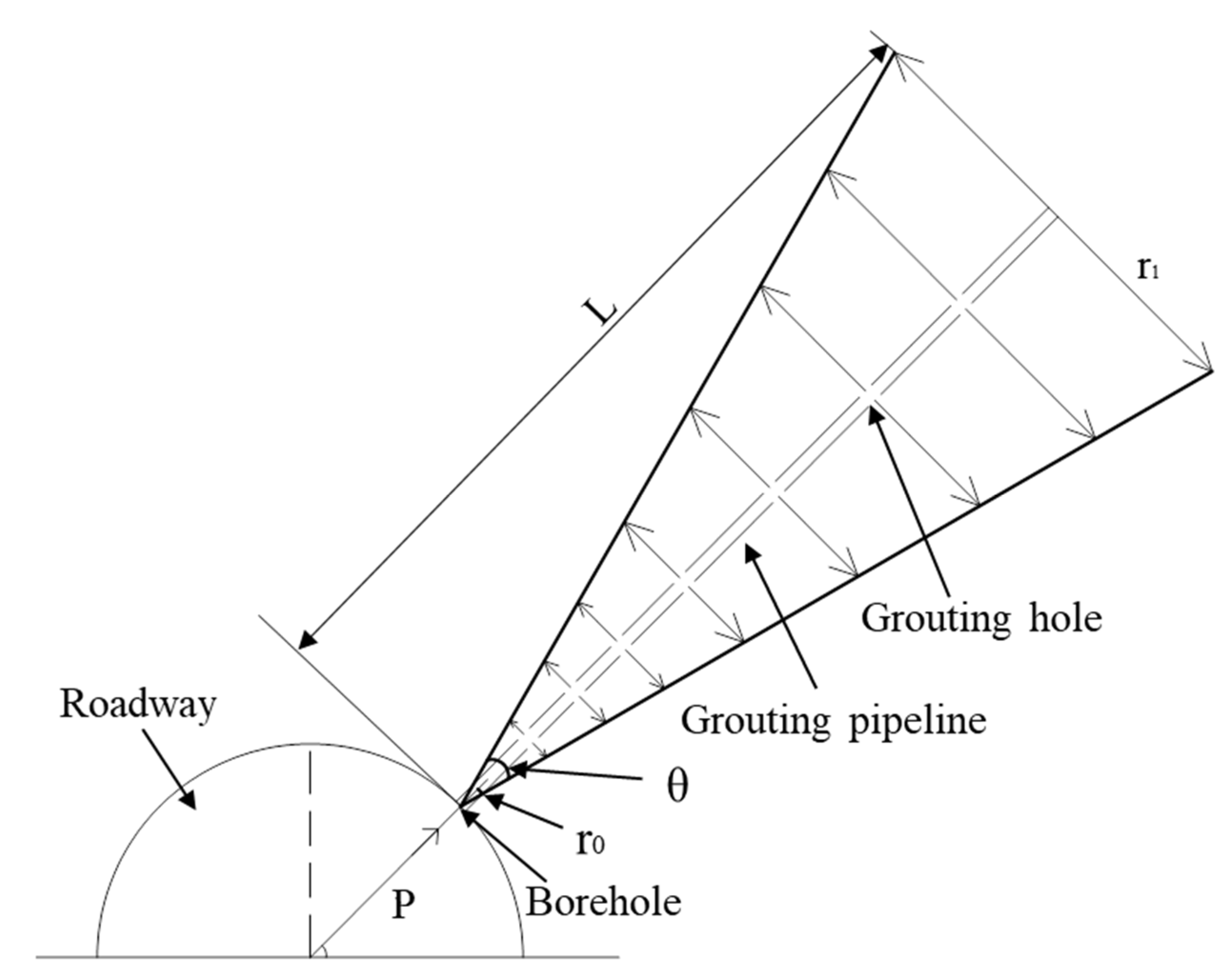
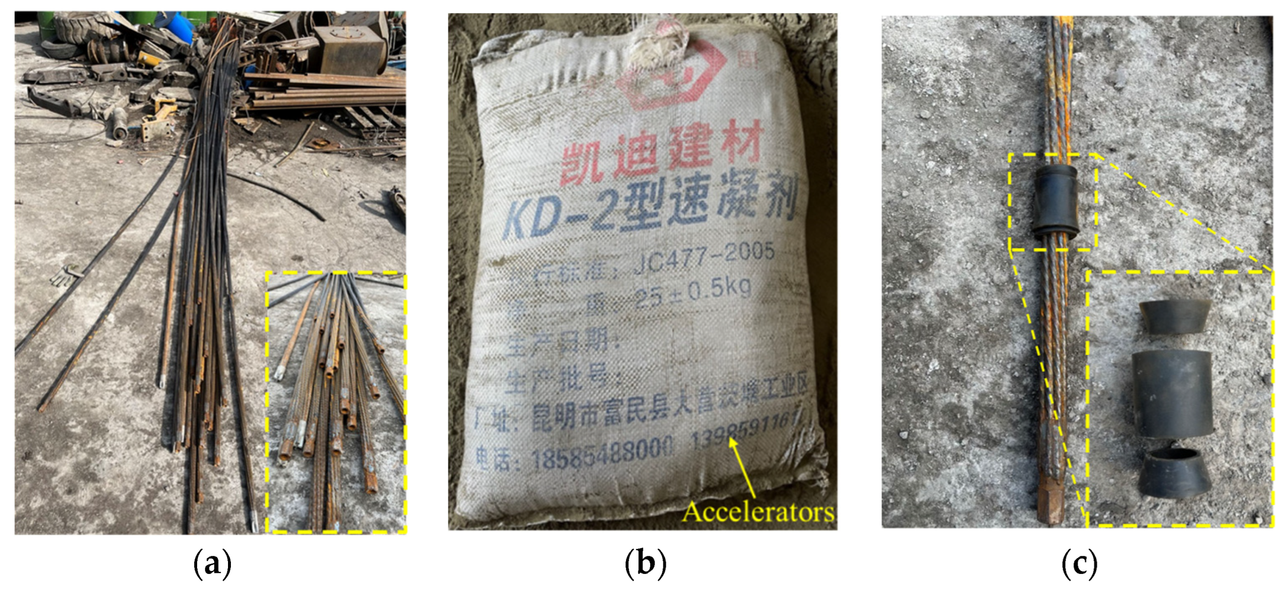
4. The Slurry Diffusion Theory of Hollow Grouted Anchor Cable (HGC)

Grouting can make the slurry flow into the cracks of the injected rock mass to improve the looseness and strength of the rock mass, and the size of the grouting diffusion radius determines the advantages and disadvantages of the grouting effect. Therefore, in order to achieve the best grouting effect in the CUSG support method, the grouting diffusion radius should be calculated theoretically. According to the previous grouting construction experience on site, in the process of grouting surrounding rock with HGC, the slurry flows from the grouting hole of the borehole to the end of the anchor cable, and then the grout begins to return and permeate along the way through the grouting hole in the middle of the grouting anchor cable. Because the slurry always flows to the end of the anchor cable, the slurry pressure at the end increases and the seepage radius expands. Therefore, the grouting range will present a conical distribution with a large tail and a small head, which may lead to the difference between the seepage formula of such grout and the spherical diffusion theory and the cylindrical diffusion theory. As such, it is impossible to effectively calculate the grouting time and slurry diffusion radius in such engineering practice. Therefore, it is urgent to derive the calculation formula of slurry diffusion radius and grouting time of HGC to guide engineering practice. Based on Maag’s seepage formula, the slurry diffusion law of HGC is studied in this paper.
First of all, the assumption of the simplified calculation model is that the injected surrounding rock is homogeneous and isotropic, and the permeability of surrounding rock is constant during grouting. The slurry is a Newtonian fluid, the slurry flows into the surrounding rock from the bottom and middle of the grouting pipe hole, the seepage of slurry in the pores of surrounding rock conforms to Darcy’s law, and the slurry diffuses conically. The slurry diffusion model is shown in Figure 9.
According to Darcy’s law and Maag’s seepage formula:
Q = k g i A t = π r 2 k g t ( d h / d r )
where Q is grouting quantity, k g is the permeability coefficient of slurry in surrounding rock, i is the hydraulic gradient of slurry, A is the seepage section area of slurry, t is grouting time, h is grouting pressure head, r is the diffusion radius of slurry, and i = d h d r , and k g = k β .
Simplified Formula (2) to obtain:
d h = Q β π r 2 k t · d r
where β is the viscosity ratio of slurry to water and k is the permeability coefficient of surrounding rock.
Simplify further to obtain:
h = Q β π k t · 1 r
If r = r 0 , h = H ; if r = r 1 , h = h 0 . the relationship between r 0 , r 1 , H and h 0 is as follows:
h 1 = H h 0 = Q β π k t · 1 r 0 Q β π k t · 1 r 1 = Q β π k t ( 1 r 0 1 r 1 )
where r 0 is the radius of grouting pipe, H is sum of grouting pressure head, r 1 is maximum diffusion radius of slurry, and h 0 is groundwater pressure head of grouted strata.
The grouting quantity of HGC is
Q = 1 3 π r 1 2 L δ
Formula (4) is introduced into Formula (5) to obtain
1 3 π r 1 2 L δ = h 1 π k t β ( 1 r 0 1 r 1 )
where L is the length of grouting pipe, δ is the porosity of surrounding rock.
Because r 1 r 0 , 1 r 0 1 r 1 1 r 0 are introduced into Formula (6) to obtain the maximum diffusion radius of slurry is
r 1 = 3 h 1 k t r 0 β δ L
The grouting time is
t = r 1 2 β δ L 3 h 1 k r 0

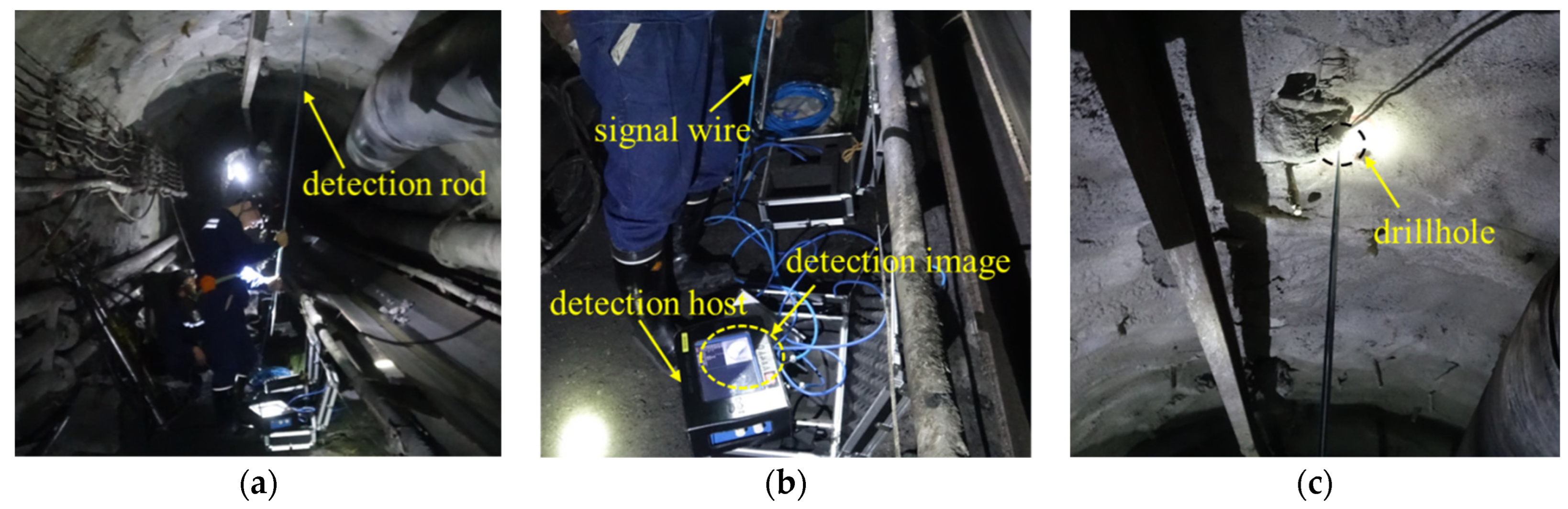
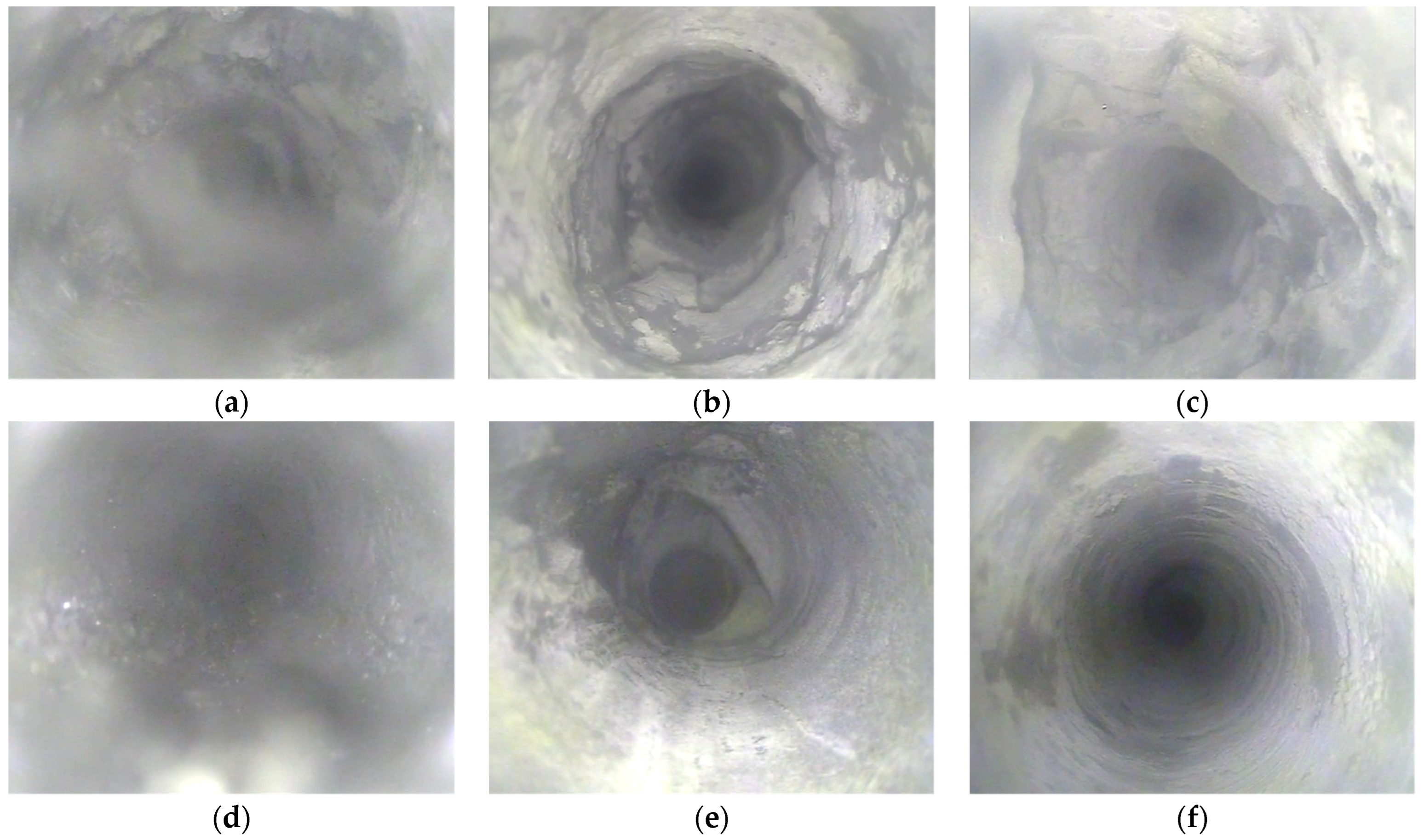
5. Engineering Application

Based on comprehensive numerical simulation and theoretical analysis combined with field experience, the CUSG support method was adopted in the subsequent excavation process of 151509 tailentry. The detailed procedures and parameters were as follows: (1) A total of 29 U-shaped steel arches shed with the corresponding specifications of lower width and middle height were used for support. The shed spacing was 500 mm, the length of beam-leg connection was 400 mm, the spacing between the upper clamp and the middle clamp wsa 220 mm, and the middle clamp and the lower clamp were parallel. The tightening torque of the clamp screw should not have been less than 350 N/m. (2) A total of three plus two HGCs (Figure 10a) were constructed at the top and sides of the roadway. The specifications of the hollow anchor cable were diameter × length = 21.6 × 8000 mm, and the inter-row spacing between the anchor cables was 1300 × 2000 mm. Under the conditions of five hollow grouted anchor cables, the maximum grouting radius was to reach 300 cm, as determined by calculation, to ensure the grouting effect. The actual geological conditions data, such as grouting pipe radius r 0 = 3 cm, maximum diffusion radius r 1 = 300 cm, grouting anchor cable length L = 800 cm, surrounding rock porosity δ = 25%, were put into the equation in Formula (8). It was concluded that grouting time t = 83 min, so grouting construction should ensure grouting for 83 min to make the slurry fully permeable. (3) Shotcreting. In order to prevent slurry leakage, the roadway must be sprayed before grouting. The mixing ratio of cement mortar was cement:sand = 1:5.5, and the proportion of accelerators (Figure 10b) was 3–5% of the amount of cement. The surface of shotcreting must have been smooth, and the exposed length of anchor cable after shotcreting was not more than 150 mm. (4) Grouting. After the shotcreting was completed, grouting could performed only after the was solidified, and the construction was carried out from the top to the side. The grouting adopted single cement slurry, and the cement adopted P.O42.5 type. The ratio was cement:water = 1.5:1 (ratio of weight), and the final pressure of the grouting was designed to be 2 MPa. According to the amount of grouting in the field, the final pressure of grouting can be appropriately adjusted, but the maximum not more than 4 MPa. In the grouting process, the slurry blocking rubber sleeve (as shown in Figure 10c) was installed at the grouting mouth of the end of the anchor cable to prevent the overflowing of the slurry from the end of the anchor cable during the grouting process. However, the floor heave caused by roadway excavation can be solved by artificial levelling of the floor in the future as the roadway floor is not supported.
In order to test the grouting effect, measuring stations were arranged in the non-grouting area and the grouting area (30 m apart) in the follow-up driving area of the 151509 tailentry, and a drillhole imager was used for drillhole detection (Figure 11). The images of partial depth positions of the detection drillholes were captured in Figure 12. The analysis of the collected results showed that the surrounding rock of the non-grouting area was broken and unstable, and the cracks were penetrated and rich. Multiple detection drillholes collapsed, and the surrounding rock failed to form a complete bearing body. Under the influence of driving and mining disturbance, the stress of the surrounding rock will be redistributed, resulting in the failure of the HGC, affecting the internal stability of the surrounding rock and seriously threatening the safe production of the mine. However, the grouting area improved the mechanical properties of the broken surrounding rock due to the bonding effect of permeable slurry, made the surrounding rock and anchor cable interact and form a unified bearing structure, greatly enhanced the constraint effect on the overlying strata, and greatly improved the stability of the roadway.
The CUSG method was used to support the 151509 tailentry, and the support strength was greatly improved. From the excavation period to the end of the roadway mining, the roadway does not need to be repaired, which has high practicability. See Figure 13 for a comparison of the roadway state under original support and CUSG support.

6. Conclusions

(1) Aiming to solve the serious problem of the deformation of 151509 gob-side coal-rock tailentry in a mine in Guizhou under the original U-shaped steel support, the CUSG surrounding rock control technology of gob-side coal-rock roadway under the influence of dynamic pressure was proposed, and a numerical simulation was used for calculation. The analysis showed that the plastic zone distribution, deformation, and stress change of roadway surrounding rock under the CUSG support were much better than those under the no support, U-shaped steel support, and anchor cable support. The CUSG support has high practical significance.
(2) Based on Darcy’s law and Maag’s seepage formula, the slurry diffusion model of HGC was established, and the calculation formulas of the maximum diffusion radius and grouting time of the slurry were derived. The actual production geological conditions of the 151509 tailentry were put into the formula, and the optimal grouting time was calculated, which guided the field construction and proved the applicability of the formula.
(3) In the subsequent construction of 151509 tailentry, the CUSG support technology was adopted, and a borehole peeper was used to detect the surrounding rock of the non-grouting area (using anchor cable + U-shaped steel + shotcreting) and the grouting area (completely using CUSG). It was found that the surrounding rock of the non-grouting area was still relatively broken and had poor stability, while the surrounding rock of the grouting area was complete, which proved that the CUSG support could change the characteristics of the surrounding rock and improve its bearing. As can be observed, the supporting effect was good from the driving period to the end of the mining roadway, no roadway repair was required, and the CUSG support method can be popularized widely.

Author Contributions

Conceptualization, P.L. and L.G.; methodology, P.L. and L.G.; software, P.Z. and C.W.; validation, G.W., L.G. and P.L.; formal analysis, P.L.; investigation, P.L., L.G., X.K., Z.M., D.K. and S.H.; resources, L.G.; data curation, P.L.; writing—original draft preparation, P.L.; writing—review and editing, L.G.; visualization, L.G. and P.L.; supervision, P.L.; project administration, P.L.; funding acquisition, L.G. and X.K. All authors have read and agreed to the published version of the manuscript.

Funding

This research was funded by the National Natural Science Foundation of China (nos. 52004073 and 52064009); the Science and Technology Support Plan of Guizhou Province (no. Qian Ke He Zhi Cheng [2021] General 400); the Science and Technology Foundation of Guizhou Province (no. Qian Ke He Ji Chu [2020] 1Y216); the Scientific Research Project for Talents Introduction of Guizhou University (no. Gui Da Ren Ji He Zi (2020) no. 42); the Cultivation Project of Guizhou University (no. Guidapeiyu [2019] no. 27); the Open Project Fund of Key Laboratory of Mining Disaster Prevention and Control (no. SMDPC202106) during the research.

Institutional Review Board Statement

The study did not require ethical approval.

Informed Consent Statement

Informed consent was obtained from all subjects involved in the study.

Data Availability Statement

All data and/or models used in the study appear in the submitted article.

Conflicts of Interest

The authors declare no conflict of interest.

References

  1. Xu, Y.; Chen, J.; Bai, J.B. Control of floor heaves with steel pile in gob-side entry retaining. Int. J. Min. Sci. Technol. 2016, 26, 527–534. [Google Scholar] [CrossRef]
  2. Hua, X.Z.; Li, Y.F. Mechanics analysis on floor deformation of gob-side entry retaining and prevention and control of floor heave. J. China Coal Soc. 2016, 41, 1624–1631. [Google Scholar]
  3. Ye, G.X.; Zhu, Q.J.; Li, S.X.; Yu, Z.X. Development and application of composite filling body in gob-side entry retaining with 1000 m-plus deep coal mine. J. Min. Saf. Eng. 2016, 33, 787–794. [Google Scholar]
  4. Sun, X.M.; Liu, X.; Liang, G.F.; Wang, D.; Jiang, Y.L. Key parameters of gob-side entry retaining formed by roof cut and pressure releasing in thin coal seams. Chin. J. Rock Mech. Eng. 2014, 33, 1449–1456. [Google Scholar]
  5. Han, C.L.; Zhang, N.; Ran, Z.; Gao, R.; Yang, H.Q. Superposed disturbance mechanism of sequential overlying strata collapse for gob-side entry retaining and corresponding control strategies. J. Cent. South Univ. 2018, 25, 2258–2271. [Google Scholar] [CrossRef]
  6. Xie, S.R.; Li, S.J.; Huang, X.; Sun, Y.D.; Yang, J.H.; Qiao, S.X. Surrounding rock principal stress difference evolution law and control of gob-side entry driving in deep mine. J. China Coal Soc. 2015, 40, 2355–2360. [Google Scholar]
  7. He, M.C.; Gao, Y.B.; Yang, J.; Gong, W.L. An innovative approach for gob-Side entry retaining in thick coal seam longwall mining. Energies 2017, 10, 1785. [Google Scholar] [CrossRef] [Green Version]
  8. Sun, X.M.; Li, G.; Song, P.; Miao, C.Y.; Zhao, C.W. Application research on gob-side entry retaining methods in no. 1200 working face in Zhongxing mine. Geotech. Geol. Eng. 2019, 37, 185–200. [Google Scholar]
  9. Gao, L.; Liu, P.Z.; Zhang, P.D.; Wu, G.Y.; Kang, X.T. Influence of Fracture Types of Main Roof on the Stability of Surrounding Rock of the Gob-Side Coal-Rock Roadway in Inclined Coal Seams and Its Engineering Application. Goal Geology & Exploration. 2022. Available online: https://kns.cnki.net/kcms/detail/61.1155.p.20220416.0838.002.html (accessed on 5 April 2022).
  10. Shi, X.S.; Jing, H.W.; Zhao, Z.L.; Gao, Y.; Zhang, Y.C.; Bu, R.D. Physical experiment and numerical modeling on the failure mechanism of gob-side entry driven in thick coal seam. Energies 2020, 13, 5425. [Google Scholar] [CrossRef]
  11. Hou, C.J.; Li, X.H. Stability principle of big and small structures of rock surrounding roadway driven along goaf in fully mechanized top coal caving face. J. China Coal Soc. 2001, 26, 1–7. [Google Scholar]
  12. Han, G.; Dou, L.M.; Zhang, Y.; Li, X.D.; Wang, Q.; Lv, Y.L. Influence mechanism and prevention technology of dynamic manifestation of roadway along goaf. J. Min. Saf. Eng. 2021, 38, 730–748. [Google Scholar]
  13. Zhang, L.; Zhao, J.; Zang, C.W.; Wang, S.L. An innovative approach for gob-side entry retaining by roof cutting in steeply pitching seam longwall mining with hard roof: A case study. Min. Met. Explor. 2020, 37, 1079–1091. [Google Scholar] [CrossRef]
  14. Wang, M.; Bai, J.B.; Wang, X.Y.; Chen, B.; Han, Z.T. Stability and control technology of overlying structure in gob-side entry driving roadways of deep inclined coal seam. J. Min. Saf. Eng. 2015, 32, 426–432. [Google Scholar]
  15. Wu, H.; Zhu, C.Q.; Li, Q.F. Study on surrounding rock stability mechanism of gob-side entry retaining with prefabricated fracture. Adv. Civ. Eng. 2021, 2021, 5819672. [Google Scholar] [CrossRef]
  16. Wang, Z.Q.; Wang, P.; Lv, W.Y.; Shi, L.; Su, Z.H.; Wu, C.; Yu, F. Mechanism and control of asymmetric floor heave in gob-side entry. J. Min. Saf. Eng. 2021, 38, 215–226. [Google Scholar]
  17. Bai, J.B.; Wang, W.J.; Hou, C.J.; Huang, H.F. Control mechanism and support technique about gateway driven along goaf in fully mechanized top coal caving face. J. China Coal Soc. 2000, 25, 478–481. [Google Scholar]
  18. Qin, T.; Ren, K.; Jiang, C.; Duan, Y.W.; Liu, Z.; Wang, L. Distribution law of mining stress of the gob-side entry retaining in deep mining thin coal seam. Adv. Civ. Eng. 2021, 2021, 5589948. [Google Scholar] [CrossRef]
  19. Basarir, H.; Oge, I.; Aydin, O. Prediction of the stresses around main and tail gates during top coal caving by 3D numerical analysis. Int. J. Rock Mech. Min. Sci. 2015, 76, 88–97. [Google Scholar] [CrossRef]
  20. Jiang, W.; Ju, W.J.; Wang, Z.L.; Zhang, Z.; Shi, M. Characteristics of overburden stress distribution and rational pillar width determination of gob-side roadway with thick and hard basic roof in fully mechanized top coal caving workface. J. Min. Saf. Eng. 2020, 37, 1142–1151. [Google Scholar]
  21. Wilson, A. The stability of underground workings in the soft rocks of the coal. Int. J. Min. Eng. 1983, 1, 91–187. [Google Scholar] [CrossRef]
  22. Shabnimashcool, M.; Li, C.C. Numerical modeling of longwall mining and stability analysis of the gates in a mine. Int. J. Rock Mech. Min. Sci. 2012, 51, 24–34. [Google Scholar] [CrossRef]
  23. Zhao, G.Z.; Ma, Z.G.; Sun, K.; Fan, J.Q.; Li, K. Research on deformation controlling mechanism of the narrow pillar of roadway driving along next goaf. J. Min. Saf. Eng. 2010, 27, 517–521. [Google Scholar]
  24. Arthur, F.A.; Zeshan, H.; Tiile, R.N. Pillar stability analysis at Missouri S&T dolomitic limestone experimental mine Proc. In Proceedings of the 50th US Rock Mechanics/Geomechanics Symp, Houston, TX, USA, 26–29 June 2016. [Google Scholar]
  25. Zheng, X.G.; An, T.L.; Guo, Y.; Liu, C.C.; Cheng, X. Surrounding rock control mechanism and engineering application of in-situ coal pillar in gob-side entry retaining. J. Min. Saf. Eng. 2018, 35, 1091–1098. [Google Scholar]
  26. Tian, Z.J.; Zhang, Z.Z.; Deng, M.; Yan, S.; Bai, J.B. Gob-side entry retained with soft roof, floor, and seam in thin coal seams: A Case Study. Sustainability 2020, 12, 1197. [Google Scholar] [CrossRef] [Green Version]
  27. Zhang, N.; Han, C.L.; Kan, J.G.; Zheng, X.G. Theory and practice of surrounding rock control for pillarless gob-side entry retaining. J. China Coal Soc. 2014, 39, 1635–1641. [Google Scholar]
  28. He, F.L.; Gao, F.; Sun, Y.J.; Li, S.J.; Song, B.H.; Yang, Y.F. Multiple-cable-girder-truss asymmetric support mechanism and its application in the roadway of fully mechanized top coal caving face with narrow coal pillar. J. China Coal Soc. 2015, 40, 2296–2302. [Google Scholar]
  29. Peng, W.Q.; Zhu, H.; Wang, Q.; Peng, G. Study on safety control of large-section roadway with high stress and broken surrounding rock. Adv. Civ. Eng. 2021, 2021, 6686208. [Google Scholar] [CrossRef]
  30. Wang, K.; Wang, L.G.; Ren, B. Failure mechanism analysis and support technology for roadway tunnel in fault fracture zone: A Case Study. Energies 2021, 14, 3767. [Google Scholar] [CrossRef]
  31. Huang, W.H.; Zhang, K.M.; Tang, X.Y.; Zhao, Z.G.; Wan, H. Coking coals potential resources prediction in deep coal beds in Northern China. Energy Explor. Exploit. 2010, 28, 313–324. [Google Scholar] [CrossRef]
  32. Kong, D.Z.; Xiong, Y.; Cheng, Z.B.; Wang, N.; Wu, G.Y.; Liu, Y. Stability analysis of coal face based on coal face-support-roof-system in steeply inclined coal seam. Geomech. Eng. 2021, 25, 233–243. [Google Scholar]
  33. Zhang, P.D.; Gao, L.; Liu, P.Z.; Wang, Y.Y.; Liu, P.; Kang, X.T. Study on the influence of borehole water content on bolt anchoring force in soft surrounding rock. Shock. Vib. 2022, 2022, 2384626. [Google Scholar] [CrossRef]
  34. Gao, L.; Zhao, S.H.; Huang, X.F.; Ma, Z.Q.; Kong, D.Z.; Kang, X.T.; Han, S. Experimental Study on Surrounding Rock Characteristics of Gateway in Panjiang Mining Area. J. GZU. (Nat. Sci.) 2022. Available online: http://kns.cnki.net/kcms/detail/52.5002.N.20220412.0956.002.html (accessed on 13 April 2022).
  35. Shan, R.L.; Peng, Y.H.; Kong, X.S.; Xiao, Y.H.; Yuan, H.H.; Huang, B.; Zheng, Y. Research progress of coal roadway support technology at home and abroad. Chin. J. Rock. Mech. Eng. 2019, 38, 2377–2403. [Google Scholar]
  36. Kang, H.P.; Wang, J.H.; Lin, J. Study and applications of roadway support techniques for coal mines. J. China Coal Soc. 2010, 35, 1809–1814. [Google Scholar]
  37. Hua, X.Z. Development status and improved proposals on gob-side entry retaining support technology in China. Coal Sci. Technol. 2006, 34, 18–81. [Google Scholar]
  38. He, M.C.; Chen, S.Y.; Guo, Z.B.; Yang, J.; Gao, Y.B. Control of surrounding rock structure for gob-side entry retaining by cutting roof to release pressure and its engineering application. J. China Univ. Min. Technol. 2017, 46, 960–969. [Google Scholar]
  39. Bai, J.B.; Zhou, H.Q.; Hou, C.J.; Tu, X.Z.; Yue, D.Z. Development of support technology beside roadway in goaf-side entry retaining for next sublevel. J. China Univ. Min. Technol. 2004, 33, 183–186. [Google Scholar]
  40. Shimada, H.; Hamanaka, A.; Sasaoka, T.; Matsui, K. Behaviour of grouting material used for floor reinforcement in underground mines. Int. J. Min. Reclam. Environ. 2014, 28, 133–148. [Google Scholar] [CrossRef]
  41. Widmann, R. International society for rock mechanics commission on rock grouting. Int. J. Rock Mech. Min. Sci. Geomech. Abstr. 1996, 33, 803–847. [Google Scholar] [CrossRef]
  42. Lee, J.S.; Sagong, M.; Park, J.; Choi, I.Y. Experimental analysis of penetration grouting in umbrella arch method for tunnel reinforcement. Int. J. Rock Mech. Min. Sci. 2020, 130, 104346. [Google Scholar] [CrossRef]
  43. Salimiana, M.H.; Baghbanana, A.; Hashemolhosseinib, H.; Dehghanipoodeha, M.; Norouzic, S. Effect of grouting on shear behavior of rock joint. Int. J. Rock Mech. Min. Sci. 2017, 98, 159–166. [Google Scholar] [CrossRef]
  44. Lu, Y.L.; Wang, L.G.; Li, Z.L.; Sun, H.Y. Experimental Study on the Shear Behavior of Regular Sandstone Joints Filled with Cement Grout. Rock Mech. Rock Eng. 2017, 50, 1321–1336. [Google Scholar] [CrossRef]
  45. Wang, L.G.; Li, M.Y.; Wang, X.Z. Study of mechanisms and technology for bolting and grouting in special soft rock roadways under high stresses. Chin. J. Rock. Mech. Eng. 2005, 24, 2889–2893. [Google Scholar]
  46. Liu, Y.X.; Gao, M.S.; He, Y.L.; Yu, X.; Xu, D. Study of control technology about gob-side entry driving with top-coal caving in inclined extra-thick coal seam. J. China Univ. Min. Technol. 2021, 50, 1051–1059. [Google Scholar]
Figure 1. (a) Location of the coal mine, Guizhou, China. (b) Plan view of the main roadway in the shaft bottom of the coal mine in Guizhou Province.
Processes 10 00863 g001
Figure 2. Strata histogram and geologic description.
Processes 10 00863 g002
Figure 3. Failure characteristics in the 151509 tailentry. (a) Roof subsidence, (b) broken rock falling, and (c) floor heave.
Processes 10 00863 g003
Figure 4. Numerical model for the surrounding rock of tailentry.
Processes 10 00863 g004
Figure 5. View of numerical model of four supporting methods. (a) No support, (b) U-shaped steel, (c) anchor cable, and (d) CUSG.
Processes 10 00863 g005
Figure 6. The distribution of plastic zone of surrounding rock under different supporting methods. (a) No support, (b) U-shaped steel, (c) anchor cable, (d) CUSG, and (e) state description.
Processes 10 00863 g006
Figure 7. Displacement evolution. (a) Distance from roof, (b) distance from floor, (c) distance from left side, and (d) distance from right side.
Processes 10 00863 g007
Figure 8. Stress evolution. (a) Distance from roof, (b) distance from floor, (c) distance from wall, and (d) distance from pillar.
Processes 10 00863 g008
Figure 9. Slurry diffusion model.
Processes 10 00863 g009
Figure 10. Materials used for CUSG support. (a) Hollow grouted anchor cable, (b) KD-2 accelerators, and (c) slurry blocking rubber sleeve.
Processes 10 00863 g010
Figure 11. Drillhole detection in the field. (a) Impel detection rod, (b) observation of internal situation, and (c) drillhole location.
Processes 10 00863 g011
Figure 12. Comparison diagram of drillholes in grouting and non-grouting area under CUSG support. (a) Non-grouting gob, (b) non-grouting roof, (c) non-grouting coal wall, (d) grouting gob, (e) grouting roof, (f) grouting coal wall.
Processes 10 00863 g012
Figure 13. Roadway state before and after using CUSG support. (a) Primary support, (b) CUSG support.
Processes 10 00863 g013
Table 1. Micro-parameters for the strata.
LithologyDensity
(kg/m3)
Bulk
(GPa)
Shear
(GPa)
Cohesion
(MPa)
Friction
(°)
Tension
(MPa)
overlying strata250012.007.602.30283.00
Fine sandstone232510.857.007.90311.10
argillaceous-siltstone237011.907.808.60331.00
15#coal13950.750.230.21130.95
argillaceous-siltstone237011.907.808.60331.00
Fine sandstone232510.857.007.90311.10
Underlying strata250012.007.602.30283.00
Table 2. Micro-parameters for the support material.
MaterialCross-Sectional Area (m2)Young
(GPa)
PoissonMoi
(m4)
Tension
(GPa)
Grout Stiffness
(MPa)
Cohesion
(MPa)
U shaped steel6.0 × 10−32.0 × 1030.32.0 × 10−8---
Anchor cable1.5 × 10−3210- 10.020.022.0
Publisher’s Note: MDPI stays neutral with regard to jurisdictional claims in published maps and institutional affiliations.

