Article

Development and Application of SONIC Divertor Simulation Code to Power Exhaust Design of Japanese DEMO Divertor

by
Nobuyuki Asakura
1,*,
Kazuo Hoshino
2,
Yuki Homma
3,
Yoshiteru Sakamoto
3 and
Joint Special Design Team for Fusion DEMO
1
National Institutes for Quantum Science and Technology (QST), Naka 311-0193, Japan
2
Graduate School of Science and Technology, Keio University, Yokohama 223-8522, Japan
3
National Institutes for Quantum Science and Technology (QST), Rokkasho 039-3212, Japan
*
Author to whom correspondence should be addressed.
Joint Special Design Team for Fusion DEMO, Rokkasho 039-3212, Japan.
Processes 2022, 10(5), 872; https://doi.org/10.3390/pr10050872
Submission received: 1 March 2022 / Revised: 15 April 2022 / Accepted: 20 April 2022 / Published: 28 April 2022
(This article belongs to the Special Issue Computational Fluid Dynamics (CFD) Simulations for Fusion Reactors)

Abstract

:
An integrated divertor simulation code, SONIC, has been developed in order to predict a self-consistent transport solution of the plasma, neutral and impurities in the scrape-off layer (SOL) and divertor. SONIC code has contributed to determining the divertor design and power handling scenarios for the Japanese (JA) fusion demonstration (DEMO) reactor. Radiative cooling scenario of Ar impurity seeding and the divertor performance have been demonstrated to evaluate the power exhaust scenarios with Psep = 230–290 MW. The simulation identified the decay length of the total parallel heat flux profile as being broader than the electron one, because of the ion convective transport from the outer divertor to the upstream SOL, produced by the plasma flow reversal. The flow reversal also reduced the impurity retention in the outer divertor, which may produce the partial detachment. Divertor operation margin of key power exhaust parameters to satisfy the peak qtarget ≤ 10 MWm−2 was determined in the low nesep of 2 − 3 × 10¹⁹ m−3 under severe conditions such as reducing radiation loss fraction, i.e., f*raddiv = (Pradsol + Praddiv)/Psep and diffusion coefficients (χ and D). The divertor geometry and reference parameters (f*raddiv ~ 0.8, χ = 1 m2s−1, D = 0.3 m2s−1) were consistent with the low nesep operation of the JA DEMO concepts. For either severe assumption of f*raddiv ~ 0.7 or χ and D to their half values, higher nesep operation was required. In addition, recent investigations of physics models (temperature-gradient force on impurity, photon transport, neutral–neutral collision) under the DEMO relevant SOL and divertor condition are presented.

1. Introduction: SONIC Code and Application to Japanese DEMO Designs

An integrated divertor simulation code, SONIC (SOLDOR, NEUT2D and IMPMC codes), has been developed over almost two decades by QST (Fusion energy directorate was united from JAEA: Japan Atomic Energy Agency) [1,2], in order to predict a self-consistent transport solution of the plasma, neutral and impurities in the scrape-off layer (SOL) and divertor, where magnetic field lines are attached to the divertor target plates at both ends. SONIC code consists of a two-dimensional multi-fluid model for the SOL and divertor plasma (SOLDOR), and neutral and impurity transport codes using Monte-Carlo (MC) techniques (NEUT2D and IMPMC, respectively). Three codes are calculated self-consistently to achieve a steady-state solution. Fundamental equations and modeling of the SONIC code are shown and explained in Reference [2]. Transport equations of plasma particles, momentum, and ion and electron energies in SOLDOR are basically identical to B2-code [3]. Transport of neutral and molecular particles is traced inside the whole vessel by NEUT2D, and distributions of their densities are provided to calculate source and loss terms in the plasma transport equations, where energy and momentum source terms arising from the atomic and molecular reactions are adapted from the DEGAS code [4,5]. The IMPMC code has been developed to calculate the impurity transport processes of atom and all charge-state ions under the background plasma and neutral conditions, as well as their generation and interaction processes between impurities and vessel walls [6,7]. It can handle kinetic effects on the impurity ions in the original formula, such as diffusion in the velocity space by Coulomb collisions with the plasma ions. Poloidal and radial distributions of the intrinsic and seeding impurities inside the whole vessel are provided. The radiation power is calculated using the effective ionization coefficients, the line emissions from excitation and effective recombination coefficients of all atomic charge states from ADAS data (ADF11). The IMPMC code is regularly implicated in the SONIC code [8].
The SONIC code has been applied to investigate the plasma detachment in JT-60U experiments [9,10,11,12,13], and to design the divertor and operation scenario for JT-60SA [1,14,15,16,17,18,19,20,21,22]. Effects of diffusion coefficients in the private flux region and outer SOL, and carbon chemical process on the plasma detachment, were investigated in the JT-60U divertor [12,13]. At the onset of the plasma detachment, reductions of both ion flux and plasma pressure (“roll-over”) were qualitatively reproduced at the divertor target with increasing SOL plasma electron density (nesep). In the simulation, ratio of the plasma pressure at the outer target when compared to the upstream one at the divertor throat (X-point) was reduced from ~1 to 0.2–0.3 at high nesep, which was produced mainly by a volume recombination process near the divertor target due to reduction of the plasma temperature (Tediv) to ~1 eV. While the trend of Tediv reduction from above 10 to ~1 eV was similar to the measurements by target Langmuir probe array, Tediv was generally smaller and nediv was larger than those of the measurement. Thus, in the simulation, neutral recycling in the divertor was enhanced when compared to the experiment. Enhancement of the diffusion coefficient in the private flux region reduced nediv more than that in the SOL region, approaching to the experiment. While the roll-over of the ion flux was reproduced at the onset of the plasma detachment, the reduction was 15–30% for all cases, which was smaller than the measurement (70–80% reduction near the separatrix). Further developments of the plasma and neutral transport models are still necessary to quantitatively simulate both the divertor plasma and its detachment. SONIC was also applied to the JET-ILW divertor in order to understand detachment physics processes, and density scan simulations with similar input parameters as the EDGE2D-EIRENE were carried out [23].
One of the important key physics processes to affect the divertor plasma performance is modeling of various drifts such as B × B and E × B, which is not incorporated in the SONIC (SOLDOR) code. Effects of the drifts on the detachment onset and the peak heat load at the target (qtarget) have been recently simulated to determine operation conditions for the International Thermonuclear Experimental Reactor (ITER) divertor by SOLPS-ITER [24,25], and results of the density scan were compared to the previous results by SOLPS4.3 without incorporating drifts. Effects of the drifts on the plasma and impurity transport in both SOL and divertor were significant at lower nesep under attached divertor condition. Since the outer qtarget became larger than 10 MWm−2, the drift effect may have a large impact on the ITER operation scenario. On the other hand, the effect was small under the detached divertor condition, where the inner and outer qtarget became similar (difference less than 20%) and both were less than 10 MWm−2. While some transient cases of the attached divertor operation should be considered, the detached divertor operation is a crucial for the DEMO rector design. Thus, the SONIC simulation will provide feasible results for the DEMO divertor design and operation scenario. Validation of SOLDOR and NEUT2D packages was so far confirmed by benchmarking with B2.5-EIRENE (SOLPS5.0) code [26] turning off the drift effects.
Handling of large thermal power exhaust from the confined plasma is one of the most important issues for fusion reactors such as ITER and DEMO. The Japanese DEMO concept aims for steady-state operation, and fusion power (Pfusion) was decreased from 3 GW (SlimCS) [27,28] to 1.5 GW (JA DEMO) [29,30,31] in order to find a feasible divertor design solution from the viewpoints of physics, engineering and technology. The major radius (Rp) represents the reactor size, and it had increased from 5.5 to 8.5 m, which was sufficient to install enough central solenoid (CS) coils for a full inductive plasma start. Total heating power, including α-particle heating and auxiliary power (Pheat), was also decreased from 650–700 MW (SlimCS) to 380 and 440 MW for the JA DEMO 2014 case (plasma minor radius: ap = 2.42 m, plasma elongation at 95% minor radius: κ95 = 1.65, plasma current: Ip = 12.3 MA, line-averaged electron density: nemain = 8.0 × 10¹⁹ m−3, Pfusion = 1.5 GW) and the JA DEMO higher-elongation (κ95 = 1.75, thus higher Ip = 13.5 MA, nemain = 8.7 × 10¹⁹ m−3 and Pfusion = 1.7 GW) case, respectively [31]. Large power exhaust scenarios are necessary both in the main plasma and divertor by radiative cooling, seeding relatively high-Z impurities. Impurities such as argon (Ar), krypton (Kr) and xenon (Xe) are preferable for the DEMO design [28,32] in order to increase radiation loss in the main plasma (Pradmain) and to reduce the exhaust power to SOL (Psep) because of a large radiation loss rate coefficient in the high Te (>100 eV) as shown in Figure 2 of Reference [28]. In the JA DEMO designs, Ar seeding was used as a reference, since relatively large radiation loss is expected also at lower Te ≤ 50 eV in the divertor. For the steady-state JA DEMO concept, high plasma performance such as enhancement factor of H-mode confinement (HH98y2 [33]) of ~1.3 and normalized β (βN) of ~3.5 is required, thus the radiation fraction in the main plasma (fradmain = Pradmain/Pheat) is restricted to be relatively low, such as 0.2–0.4, due to enhancing fuel dilution with increasing the impurity concentration and due to degrading the plasma performance at extensively high fradmain. Thus, large power handling in the divertor and appropriate design of the divertor size and geometry are required. SONIC simulation has been applied to these DEMO divertor studies with Psep ~500 MW for SlimCS [28,34,35,36,37] and Psep = 230–290 MW for the JA DEMO cases [31,38], in order to determine their divertor geometry and power handling scenarios. In the JA DEMO cases, the divertor operation with the peak qtarget less than 10 MWm−2, corresponding to the surface temperature of the tungsten (W) target below the recrystallization (≤ 1200 °C), was foreseen in a relatively low nesep range (2–3 × 10¹⁹ m−3).
In this paper, the progress of SONIC simulation for the power exhaust scenario and the divertor design of the JA DEMO is mainly summarized. Recent developments of the SONIC code, then simulation parameters and the JA DEMO geometry are explained in Section 2. Recent simulation studies of the detachment plasma and effects of key parameters on the DEMO divertor operation are summarized in Section 3. In Section 3.1 and Section 3.2, divertor design and the reference operation scenarios for JA DEMO are determined. In Section 3.3, the effect of SOL heat flux profile on the partial detachment in the divertor is clarified. In Section 3.4, operation boundary of JA DEMO divertor is clarified for key power exhaust parameters. In Section 4, physics modeling studies important for DEMO-level SOL and divertor conditions, such as thermal force on impurity transport, photon transport and neutral–neutral collision, are shown. SONIC studies for the JA DEMO divertor design are summarized in Section 5.

2. SONIC Development and Divertor Simulation for JA DEMO

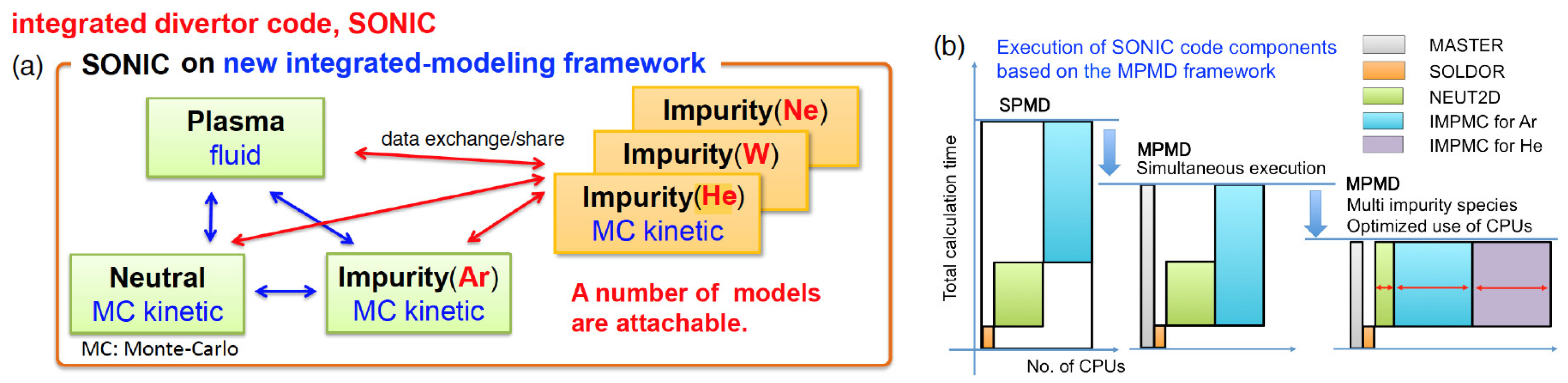
2.1. Development of SONIC Framework

SONIC code was originally developed based on the Single-Program Multiple-Data (SPMD) framework, where code components of SOLDOR, NEUT2D and IMPMC, and data-exchange structure were strongly coupled with each other. A new integrated modeling framework (SONIC version 4) using Multiple-Program Multiple-Data (MPMD) approaches and a Message Passing Interface (MPI) data exchange scheme has been developed, appropriate for multi-author code development, independent structuring of each code and further numerical efficiency [19], as shown in Figure 1. On the MPMD framework, while each code is executed independently, the framework automatically controls interaction between codes, such as data exchange. Major advantages brought by the MPMD framework are as follows; (i) each code can be independently developed, added and replaced with less effort; (ii) the number of CPUs used for each code can be arbitrarily adjusted to optimize performance. As for the first achievement by the MPMD framework, multi-impurity transport simulations have been performed by running two IMPMC codes for different species, such as for Ar-seeding scenarios of JT-60SA with intrinsic carbon (C) sputtered from the divertor plate [21,22]. Recently, simulation of helium (He) exhaust for JA DEMO has been performed in the detached divertor with Ar seeding.

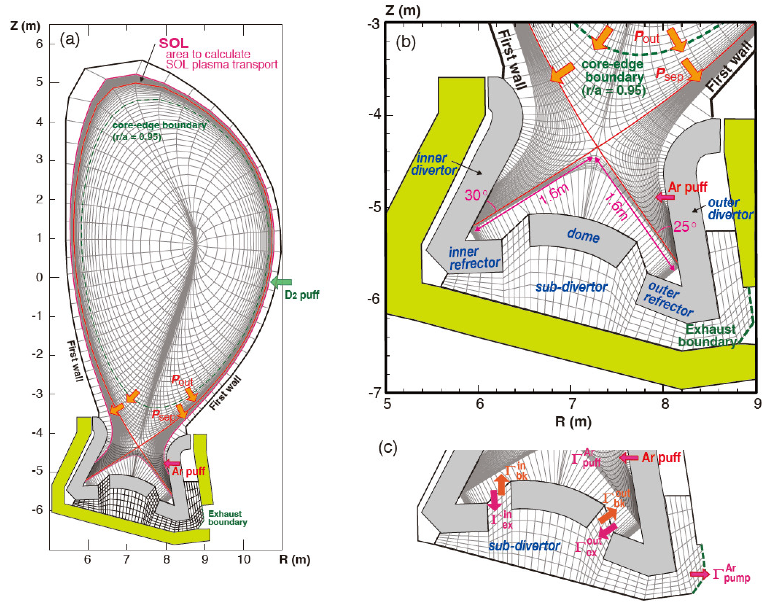
2.2. Divertor Simulation and Geometry for JA DEMO

SONIC calculation meshes of all plasma areas and enlarged divertor areas are shown in Figure 2. Plasma transport in the SOL and divertor is simulated in the flux surfaces of the outer midplane SOL radius (rmid) ≤ 3.2 cm, which covers the most SOL area, connecting between the inner and outer targets. Here, the plasma transport is not calculated in the most outer mesh area, connecting to the vessel wall, except in the divertor target. The SOL area is divided into 24 radial layers along the magnetic flux surfaces, and the radial width at the outer midplane (Δrmid) is increased from 0.7 mm (near the separatrix) to 1.3 mm (at the most outer flux surface). The inner and outer divertors cover all divertor plasma volume below the X-point, similar to ITER divertor, and the leg length (Ldiv) of 1.6 m is longer than that of ITER (1.0 m). The compression of neutral particles and efficient formation of the plasma detachment will be expected particularly near the strike-point. The poloidal angle between the separatrix and target surface at the strike point (θdiv) is designed as 30° and 25° for the inner and outer targets, respectively, where the total (magnetic and geometrical) flux expansion at the inner and outer targets, i.e., fexpdiv/sinθdiv where fexpdiv = (Bp/Bt)mid/(Bp/Bt)div, is similar (~12). The reflector is installed both at the inner and outer divertors, with the poloidal angle of 60° for the divertor design and operation window studies [31,38]. It is noted that the inner and outer reflector angles were recently increased to 90° and 80°, respectively, i.e., the V-shape corner geometry became more open. At the same time, they were extended behind the dome roof in order to protect the end-part of the cooling pipes against fast neuron irradiation from the main plasma. Influence of the “open reflector” geometry on the plasma detachment was small since the strike-point was relatively far (25 cm) from the V-shape corner.
Exhaust plasma power (Pout) and particles (Γout) from the core region are given at the core–edge boundary (the magnetic surface corresponding to rmid/ap = 0.95). Pout is equally distributed to ion and electron energy sources (Pouti = Poute = Pout/2). Psep is slightly smaller than Pout since the radiation loss in the main plasma edge (Pradedge) is small in the JA DEMO concepts, i.e., 4–7% of Pout as shown in Section 3. Cross field diffusion coefficients of ion and electron energies and plasma particle are given over all plasma simulation area as χi = χe = 1 m2s−1 and D = 0.3 m2s−1, respectively, which are the same as “standard” values in the previous ITER simulation [39]. Diffusion coefficient for the seeding impurity is given as the same value, i.e., Dimp = 0.3 m2s−1.
For the parallel energy transport terms in the SOL and the divertor, electron conduction dominates when compared to ion conduction and their convections. In the multi-fluid plasma transport code (SOLDOR), heat flux limiters for the parallel conduction (a factor limiting the conduction energy transport to a fraction of the free streaming energy) are 0.2, 10 and 0.5 for electron, ion and viscosity, respectively. In the MC transport codes, NEUT2D and IMPMC, deuterium atoms (D0) and gas (D2) and impurity atoms (Ar) are traced in all mesh areas, as shown in Figure 2, including the most outer mesh in the vessel wall and above the dome, and in the sub-divertor. D2 is injected near the device outer midplane and Ar impurity seeding is at the upper part of the outer target. They are exhausted from the sub-divertor to the outboard exhaust opening, instead of the bottom in the early design [31]. This is because of reducing the fast neutron irradiation to protect the bottom part of the vacuum vessel. Distribution of the detachment plasma was not influenced, while the pumping system should be increased due to a reduction in the conductance of the exhaust route.

2.3. MC Calculation Technique in Divertor

In the SONIC simulation, computer resources are consumed primarily for impurity transport calculations (IMPMC). In order to save the impurity atom (Ar) transport calculation in the sub-divertor, a technique to assume the impurity backflow at the exhaust slots, i.e., “backflow model”, was developed [18] and it has been incorporated in the IMPMC calculation. Ar atoms in the sub-divertor region are executed 1 in every 10 IMPMC runs, and the exhaust fluxes at the inner and outer divertor slots (Γexin and Γexout) and backflow fluxes (Γbkin and Γbkout) were calculated as shown in Figure 2c. In the following nine IMPMC runs during the SONIC conversion process, Γbkin and Γbkout are provided proportionally when the seeding rate (ΓpuffAr) changes, where Γexin and Γexout are absorbed at the divertor slots. This “backflow model” technique can also reduce oscillation to a steady-state solution, which is mainly caused by the different time scales of impurity transport between the divertor chamber and the sub-divertor. As a result, the total IMPMC calculation time is reduced significantly, and a stable solution of the SONIC simulation can be obtained. to satisfy the Ar particle balance of the net exhaust flux
Development of neutral–neutral (and neutral–molecular, molecular–molecular) elastic collision models (NNC) in NEUT2D, and influences on the plasma detachment and the divertor pressure, are described in Section 4.3. On the other hand, NNC was not activated for the divertor performance study.

3. Divertor Design and Performance for Power Exhaust

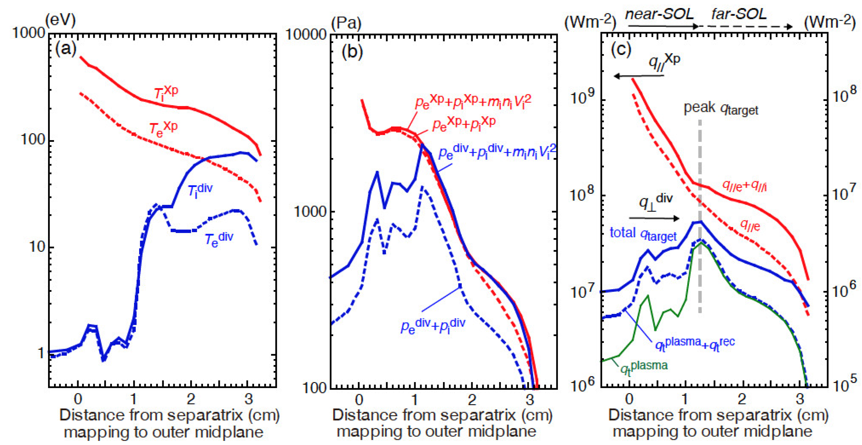
3.1. Power Exhaust Scenario and Key Parameters

The JA DEMO concepts challenge plasma performance, being higher than ITER levels, with comparable fradmain (0.2–0.4), and a large divertor power handling factor of Psep/Rp = 28–34 MWm−1, corresponding to 1.8–2.1 times larger than that of ITER (16 MWm−1). Divertor volume is increased, i.e., Rp and Ldiv are 1.37 and 1.6 times of ITER (6.2 m and 1.0 m), respectively, which will contribute to increasing the radiation power and to reducing the plasma temperature.
A simple formula of the plasma heat load (qplasma) is described by Psep, f*raddiv, λq//mid and geometry parameters, as following, qplasma = Psep·(1-f*raddiv)·(sinθdiv/fexpdiv)· 1/(4πRp·λq//mid·Sdet), where f*raddiv = (Pradsol+Praddiv)/Psep, i.e., radiation power fraction in the SOL and divertor normalized by Psep, and power reduction in the plasma detachment is represented by an additional factor (Sdet) in this simple formula. The total flux expansion is 12 as explained in Section 2.2. λq//mid is e-folding length of the parallel heat flux (q//) profile near the outer midplane separatrix, which is determined by the power balance between the plasma radial diffusion and parallel conduction. SONIC simulations evaluated profiles of the plasma density, temperature and heat load of the target as a self-consistent solution of the plasma, neutral and impurity transport processes. Particularly for the reactor design, the plasma detachment is required to significantly reduce both the plasma temperatures (Tediv, Tidiv) near the strike-points and the peak heat load (qtarget) less than 10 MWm−2 level [40]. Psep, f*raddiv and diffusion coefficients are important key parameters for the divertor performance, which have been systematically investigated by the SONIC code [38]. When compared to that of ITER (0.5–0.6) [24], larger f*raddiv is required for the larger Psep/Rp design.
High plasma density is preferable for the reactor design and power exhaust. On the other hand, restriction of ne at the main plasma separatrix (nesep) is a common issue for DEMO divertor designs [41,42], since Greenwald density (nGW = Ipap2 [1020 m−3, MA, m]) corresponds to 6.7 x10¹⁹ and 7.3 × 10¹⁹ m−3 for the JA DEMO 2014 and higher-κ designs, respectively, both of which are lower than nGW of ITER (1.1 × 10²⁰ m−3). Thus, nemain is required to be 1.2 times higher than nGW, assuming a quadratic function-like peak profile, in order to achieve the expecting Pfusion. At the same time, nesep/nGW was reported to be ~1/3 in the H-mode plasma experiments [43,44] and similar fraction in “standard” ITER simulations [39]. A recent experiment result was also lower than critical values of 0.4–0.5 [45], which was consistent with the edge ballooning stability model. As a result, the operation range of nesep/nGW is expected to be 0.3–0.5, thus the divertor performance and the operation boundary for the JA DEMO were investigated in the low density range of nesep = 2 – 3 × 10¹⁹ m−3.
SOL density (nesep) scan for the JA DEMO higher-κ case, corresponding to the lower Psep, was performed with increasing fuel gas puff rate from 25 to 150 Pam3s−1 for a given Pout = 250 MW and Γout = 1 × 10²² Ds−1 at the core–edge boundary [31]. The total radiation power in the plasma edge (0.95 < r/a < 1), SOL and divertor (Pradedge + Pradsol + Praddiv) was adjusted to be 200 MW by feedback of the Ar seeding rate in the iterative SONIC calculation. The input radiation fraction corresponded to fradin = (Pradedge + Pradsol + Praddiv)/Pout = 0.8, which was so far determined as the reference value, and this series of nesep scan was referred to as Case-1 in Reference [38]. Here, Psep (= 235–240 MW) is slightly smaller than Pout, thus f*raddiv corresponds to a slightly smaller value (~0.78). Power exhaust parameters of the reference JA DEMO 2014 scenario are Pout = 300 MW and Pradedge + Pradsol + Praddiv = 240 MW (Case-2). In addition, lower radiation fraction cases of the JA DEMO higher-κ and JA DEMO 2014 (fradinp = 0.7 for each Pout) were also investigated as Case-3 and Case-4, respectively. Lower limit of the divertor plasma operation is discussed in Section 3.4.

3.2. Radiation Loss and Plasma Detachment

Figure 3a,b show distributions of the radiation power density (Wrad) in the inner and outer divertors at nesep = 2.0 × 10¹⁹ m−3 for Case-1, corresponding to a near lower boundary of the nesep range. Total radiation powers in the two divertors are comparable, i.e., 79 and 82 MW, respectively. The large radiation peaks near the separatrix are maintained at the upstream on both divertor legs. In the inner divertor, a large Wrad is seen at 40–60 cm upstream of the target near the separatrix, and it is maintained far above the inner target. Te is decreased to ~1 eV over most of the area of the target, which we describe as “full detachment”, as shown in Figure 3c. Total heat load (qtarget) is evaluated by including surface recombination of the ions (qtrec = nidivCsdivEion, where nidiv, Csdiv and Eion are ion density, sound velocity at the divertor sheath and recombination energy, respectively), radiation power load (qtrad) and neutral flux load (qtn), in addition to the plasma heat flux (qtplasma). The peak qtarget of 4.2 MWm−2 is seen near the separatrix, mostly attributed to qtrec as shown in Figure 3e. Here, locations of multi-peaks in the qtarget profile near the strike-point change in the converged solutions, which are attributed to peaks of nediv, nidiv, Tediv and Tidiv profiles. The time-averaged profile may be more appropriate to describe the peak qtarget value.
In the outer divertor, a large Wrad is also seen at the upstream (40–60 cm) near the separatrix, where local cAr (= nAr/ni) is increased up to 2%. On the other hand, the Wrad peak shifts toward the target at the outer flux surfaces as shown in Figure 3b, and it becomes smaller than 10 MWm−3 (lowest color bar) and located just above the target (a few centimeters). The plasma detachment is produced within ~12 cm near the strike-point as shown in Figure 3d, which we describe as “partial detachment”. The peak qtarget of 5.5 MWm−2 is seen at the boundary of the attached region, where both Tediv and Tidiv are increased from 1–2 to ~15 eV, and nediv is decreased from ~1.5 × 10²² m−3 to ~1.5 × 10²¹ m−3. At the same time, the Wrad peak shifts toward the target, thus qtplasma and qtrad become dominant. In the partial detachment, the peak qtarget is sensitive to the plasma temperature and density profiles and location of the Wrad peak.
Figure 4 shows distributions of Te, Wrad, cAr, Mach number of the plasma flow (M// = Vi///Cs, where Vi// is parallel ion velocity and Cs = [(Te+Ti)/mi]0.5), the static plasma pressure (neTe + niTi) and the total plasma pressure, i.e., static and dynamic pressures (neTe + niTi + miniVi//2), along three representative magnetic field lines, corresponding to the second, sixth and ninth radial meshes outside the separatrix. The plasma detachment is produced at the former two target areas, and the peak qtarget is seen at the target in the third one (attached plasma). Along the magnetic field line near the separatrix (second radial mesh), the plasma detachment (Te and the total plasma pressure decrease to 1~2 eV and a half value of the upstream total pressure, respectively) is produced at a few 10 cm above the target as shown in Figure 4a,f. As described above, the peak qtarget is sensitive to the plasma profiles both across and along the magnetic field line. In order to simulate an abrupt change of the plasma parameters and impurity concentration near the divertor target, the mesh size is gradually reduced towards the target as shown in Figure 2b, and the minimum size (in a few cm above the target) is 1.5–3 mm in the poloidal direction (corresponding to 28–55 mm along the magnetic field line). Along the magnetic field line at the attached region (ninth radial mesh), Te (and Ti) decreased from 25 eV (15 mm above the target) to 15 eV (at the target) due to enhancement of Wrad above the target. It is noted that the plasma flow changes toward the target in the narrow region, M// is enhanced to ~0.82 at the target as shown in Figure 4d. While the static plasma pressure is decreased from 2.1 kPa to 1.5 kPa, the total plasma pressure is conserved along the magnetic field line as shown in Figure 4e,f.
Profiles of Tediv and Tidiv in the attached region are relatively flat or rather increased toward the outer SOL, but they are still lower than those at the upstream SOL, as shown in Figure 5a, where the radial distances are mapped to the same magnetic surfaces at the outer midplane. The midplane SOL width of the plasma detachment and location of the peak qtarget correspond to Δrmid ~1 and 1.25 cm, respectively. Near the separatrix, Te and Ti are significantly reduced from 380 and 812 eV at the X-point, respectively, to 1–2 eV at the target. On the other hand, Figure 5b shows that reduction in the total plasma pressure is only half in the simulation. Here, the dynamic pressure near the X-point is very small, while it is added to the static pressure, independently of the plasma flow direction. The plasma flow profile in the outer divertor and SOL is explained in Section 3.3. A significant reduction in nediv, i.e., “roll-over”, was expected, at least, by further reduction of the plasma temperature to less than ~0.5 eV, leading to enhancement of volume recombination process. Studies of atomic and molecular collision processes and/or enhancement of the plasma diffusion may be necessary to produce the further reductions in Tediv and Tidiv, leading to further reduction in the particle flux and nediv as was explained in Section 1 [13,23].
As a result, SONIC simulation showed that the peak qtarget for the reference power exhaust scenario (Case-1) can be reduced to lower than 10 MWm−2 for both inner and outer divertors even at the low nesep, which is expected near the lower boundary of the JA DEMO operation window. At the same time, large Wrad and plasma detachment can be maintained in the long divertor leg without extending to the X-point, SOL and inside the main plasma.

3.3. Influence of Heat Flux Profile on Plasma Detachment

Figure 5c compares profiles of the heat load at the outer target (qtplasma, qtplasma + qtrec, total qtarget) and the electron and total parallel heat fluxes near the X-point (q//eXp and q//eXp + q//iXp). Both q//eXp and q//eXp+q//iXp profiles are described approximately by a two-exponential function such as q//(Δrmid) = q//nearexp(−Δrmid/λq//near) + q//farexp(−Δrmid/λq//far). The decay lengths of “near-SOL” (λq//near) and “far-SOL” (λq//far) for the q//eXp profile, mostly attributed by the electron conduction, correspond to 2.2 and 9.1 mm, respectively. Both Te and Ti near the separatrix become high in the DEMO plasma due to large exhaust power and low density when compared to those of ITER. Thus, the q// profile in the SOL generally becomes narrow when compared to the ITER simulation result (3.6 mm [39]), whereas χi = χe = 1 m2s−1 and D = 0.3 m2s−1 are the same values. The SONIC simulation result shows that large q// near the separatrix (shown as “near-SOL” in Figure 5c) is mostly reduced in the divertor due to large radiation loss and detachment.
Location of the peak qtarget (Δrmid = 1.25 cm) corresponds to a boundary between the “near-SOL” and the “far-SOL” in the q//eXp + q//iXp profile, and the peak qtarget is determined mostly by the local Tediv and Tidiv, i.e., plasma heat load, as shown in Section 3.2. λq//near and λq//far of the q//eXp + q//iXp profile are 2.9 and 13.2 mm, respectively, which are larger than those of the q//eXp profile. Transition from the “near-SOL” to the “far-SOL” of the q//eXp + q//iXp profile is mostly attributed to the ion conduction and convection transports. Particularly, the convection component in q//iXp is driven from the outer divertor to the upstream SOL in the wide SOL region (Δrmid ≤ 1.7 cm), as shown in Figure 6a, and it does not contribute to the ion heat flux towards the outer divertor. Therefore, a flat “shoulder” appears in the q//iXp profile as shown in Figure 6b. The small flow reversal (M// = −0.1 ~ −0.2) is produced even above the divertor target as shown in Figure 4d, and the plasma static pressure is gradually decreased toward the upstream SOL. These simulation results suggests that it is produced above the divertor target by locally increasing neutral ionization and plasma pressure, and it is extended to the low-field-side SOL as proposed in Reference [46]. As a result, the decay length of the q//eXp + q//iXp profile is increased when compared to that of the q//eXp profile, and, at the same time, the transition from the “near-SOL” to the “far-SOL” is emphasized clearly. At the same time, as shown in Figure 4c, cAr is reduced significantly above the outer target and it is gradually increased toward the upstream SOL, in particular on the magnetic field lines, where the relatively small flow reversal (M// = −0.2) is generated. This may sustain the attached plasma region at the outer target and produce the partial detachment in the simulation.
Radial diffusion of the SOL plasma significantly affects profiles of the heat and particle fluxes. Effects of the smaller diffusion coefficients on the divertor operation were investigated. Simulations with reducing both χ and D to half values, i.e., χe = χi = 0.5 m2s−1, D = 0.15 m2s−1 and Te, Ti and ne profiles were compared in Figure 7a of Reference [38]. For the smaller χ and D case, gas puff rate was reduced to 50 Pam3s−1 in order to compare profiles at similar nesep = 2.0 × 10¹⁹ m−3, since nesep is increased by the reduction of D. Radial gradients of Te, Ti and ne profiles were increased, and ne was decreased in the whole SOL region. Te and Ti at the outer midplane separatrix (Tesep and Tisep) are increased from 360 to 390 eV, and from 820 to 1190 eV, respectively, where increases in Tisep are significant. Therefore, λq//near values of q//eXp and q//iXp profiles become smaller (from 2.3 to 1.6 mm and from 3.2 to 2.5 mm, respectively) due to reduction of the radial diffusion and enhancement of the parallel conductive transport. Figure 6c,d show the Mach number and the heat flux profiles, respectively, for the smaller χ and D case. Peak of the flow reversal shifts toward the separatrix and the “shoulder” in the q//iXp profile becomes narrow (Δrmid ≤ 1.1 cm), thus the transition from the near-SOL to the far-SOL shifts toward the separatrix. As a result, λq//near of the q//eXp + q//iXp profile is decreased from 2.9 to 2.2 mm. At the same time, transition from the near-SOL to the far-SOL becomes rather gradual. Figure 6e compares λq//near values of q//eXp and q//eXp + q//iXp profiles for the four cases (larger Psep and/or smaller f*raddiv as explained in Section 3.1). All λq//near values for the q//eXp+q//iXp profile are 1.2–1.6 times larger than those for the q//eXp profiles, and they are decreased from 2.5–3.3 mm (for reference χ and D) to 1.7–2.2 mm.
It was reported that λq//near was scaled by λq//Eich = 0.7⋅Bt−0.77q951.05Psep0.09 (mm, T, MW) [47], based on an experiment database of the heat load profile at the outer target under the attached divertor condition. The scaling predicts 1.3 mm for JA DEMO, respectively. These λq//near values are still larger than the empirical scaling (λq//Eich). Further reductions of χ and D will be required to simulate the divertor performance for the empirical SOL heat and particle flux profiles.
It is noted that the near-SOL region in the q//eXp + q//iXp profile becomes narrow and that local TeXp and TiXp at the transition to the far-SOL are increased. Influence of the upstream heat flux profile was seen in the partial detachment profile at the outer target; the width was decreased from 12 to 7 cm for Case-1 as shown in Figure 7 of Reference [38], the peak qtarget was also shifted from rdiv = 15 to 10 cm, and the peak was increased from 5.8 to 9.5 MWm−2 due to large increases in the local Tediv and Tidiv.

3.4. Divertor Operation in the Low Density SOL

Simulation results of the divertor plasma detachment and heat flux profile for the JA DEMO high-κ reference (Case-1: Psep ~235 MW and f*raddiv ~0.78), and effects of the diffusion coefficients are discussed in Section 3.2 and 3.3, respectively. Divertor operation in the low nesep range and influences of the key parameters such as Psep, f*raddiv and λq//mid on the peak qtarget were systematically investigated [38]. A higher Psep ~283 MW case with the same f*raddiv (Case-2) is another reference for JA DEMO 2014. Divertor operations for extreme cases with reducing f*raddiv to ~0.7 (Case-3 and Case-4), and all four cases with reducing χ and D were also determined.
Operation boundary of the low nesep for the standard χ and D is summarized in Figure 7c, where the peak qtarget are plotted as the function of nesep and the outer qtarget is generally larger than the inner qtarget. The power exhaust in the divertor, i.e., Psep·(1–f*raddiv), for the four cases corresponds to 50, 60, 75 and 90 MW. Circles and squares show series of reference JA DEMO higher-κ and 2014 cases, respectively, where the peak qtarget in Figure 3f is marked by an open circle. The peak qtarget is generally increased with increasing Psep·(1 –f*raddiv), and with decreasing nesep. The two series of f*raddiv ~0.8 are acceptable in predictably low nesep (≥ 2 × 10¹⁹ m−3) to reduce qtarget ≤ 10 MWm−2. The JA DEMO higher-κ case has advantages to provide enough operation margin to the recrystallization temperature of the tungsten target (~1200 °C). Triangles and diamonds show the series of lower f*raddiv (~0.7) cases. The peak qtarget is increased with reducing width of the plasma detachment, as shown in Figure 7a,b: profiles of Tediv, Tidiv, nediv and heat load components at nesep = 2.0 × 10¹⁹m−3 for the JA DEMO higher-κ case with the lower f*raddiv (the peak qtarget is also marked by an open circle in Figure 7c). The detachment width is decreased to 7 cm at the outer target, and the peak qtarget is seen at ~3 cm outside of each detach–attach boundary. The peak qtarget is significantly increased to 12.5 MWm−2 due to the increase in qtplasma, while qtrad is slightly reduced, where both the local Tediv and Tidiv increase to 33 eV, while the local nediv is similar at ~2 × 10²⁰ m−3. In the outer flux surfaces (rdiv > 20 cm), nediv is decreased to a few 1019 m−3 and Tediv and Tidiv are increased to 20–30 and 70–100 eV, respectively. Tidiv becomes larger than Tediv by a factor of three to four due to reduction in the energy exchange rate. These changes of the plasma profiles and the peak qtarget are consistent with those of the upstream SOL plasma as shown in Section 3.3, i.e., the flow reversal region is decreased in Δrmid ≤ 1.1 cm, λq//near of q//eXp and q//eXp + q//iXp profiles are decreased to 1.9 and 2.7 cm, respectively, and the transition from the near-SOL to the far-SOL of the total q//Xp profile shifts toward the separatrix. As for the two lower f*raddiv cases, higher nesep operations, i.e., nesep ≥ 2.3 × 10¹⁹ and 2.7 × 10¹⁹m−3, are required.
Results of the peak qtarget for the smaller χ and D cases are plotted by open symbols in Figure 7d. Four guidelines show results with the standard χ and D cases in Figure 7c for comparison. Similarly, the peak qtarget is increased with increasing Psep·(1 – f*raddiv) and they are reduced with increasing nesep for each case. The lower boundary of nesep for qtarget ≤ 10 MWm−2 was determined to be 2.0 × 10¹⁹ and 2.3 × 10¹⁹ m−3 for Case-1 and Case-2, respectively. Therefore, the high f*raddiv (~0.78) cases are acceptable in the low nesep operation, while higher nesep is required for Case-2. On the other hand, for the two lower f*raddiv (~0.67) cases (Case-3 and Case-4), the peak qtarget and nesep are significantly increased, thus the divertor operation is difficult in the low nesep range (2 − 3 × 10¹⁹ m−3). As a result, the reduction in χ and D to half values significantly affected the divertor power exhaust, because of a reduction of the detachment width and increases in Tediv and Tidiv at the attached region, rather than due to increase of the peak q//, as shown in Section 3.3. In order to produce the wider detachment plasma and to reduce the acceptable peak qtarget (≤ 10 MWm−2), a high f*raddiv of a level of 0.8 was necessary for the JA DEMO 2014 and JA DEMO higher-κ designs.

4. Development of SONIC Modelings for DEMO Design

Some proposals for improving physics models in the SONIC code have been investigated and influences on the divertor performance were evaluated under the DEMO SOL and divertor conditions. Further validations of simulations such as benchmarks with other divertor codes will be required to be incorporated as defaults. First, an improvement of the kinetic simulation model for the thermal force on impurity ions was proposed for the low collisionality plasma under the SOL condition in DEMO, such as Tesep of a few 100 eV, Tisep of several 100 eV and nesep of a few 1019 m−3. Second, a photon transport model for hydrogen isotopes was investigated under the detached plasma condition of the DEMO divertor, where both neutral density and divertor size are increased when compared with existing devices and ITER. Third, a neutral–neutral collision (NNC) model was implicated since neutral–neutral elastic scattering plays an important role for distributions of neutrals, molecules and detachment plasma.

4.1. Improvement of Kinetic Model in Impurity Transport

SONIC simulation results showed that the midplane cArsol for the Case-1 series was decreased from 1.3 to 0.4–0.5% with increasing the gas puff rate (and nesep), and that the divertor shielding factor (cArdiv/cArsol) was increased from 1.4 to 2.4–2.6 [31]. At the same time, cArsol was varied also in the poloidal direction, e.g., cArsol was decreased from ~1% (near X-point) to 0.4% (at outer midplane). Parallel transport of the seeding impurity ion in SOL and divertor is determined mostly by modeling of the thermal (temperature-gradient) force (TF) and friction force (FF) from the bulk ions. Conventional formula of a kinetic model [48], which is based on the collisional plasma and proportional to ∇Ti along the magnetic field line, was incorporated in the IMPMC code, and it has been used under the DEMO SOL plasma condition, i.e., low collisionality plasma.
A kinetic TF model was proposed [49,50], which incorporated a collisionality parameter and ion heat flux limiter in the conventional TF formula as a collisionality-dependent term. The model reduces TF significantly in the low collisionality SOL. Self-consistent plasma simulations were carried out for the JA DEMO higher-κ reference case. Figure 8a shows distributions of cAr along the separatrix magnetic field line from the outer target to the inner one. The conventional TF model (A) produces Ar accumulation peaks in some poloidal locations near the X-point of the low-field-side (LFS) SOL and along the high-field-side (HFS) SOL. Effects of the proposed TF model on the cAr profile were evaluated for (B), assuming the same profiles of plasma temperature, density and flow velocity for the conventional model (A); cAr is significantly decreased over all SOL regions (above the X-point). On the other hand, a self-consistent SONIC solution of the proposed model (C) shows that TF is reduced by 20–80% in the SOL when compared to the conventional TF model (A), and that the local accumulation peaks of cAr are reduced. While the averaged cAr level is reduced slightly in the overall SOL region, it is comparable near the outer midplane. A similar effect was also observed in the poloidal profile of Wrad as shown in Figure 8b. Here, the total heat load on the target was comparable since the total Pradsol and Praddiv were adjusted to be comparable (~190 MW and f*raddiv~0.78) for (A) and (C) cases by feedback of the Ar seeding rate. In the overall SOL region, Pradsol is reduced by 18%, which corresponds to the reduction in the cArsol level. At the same time, Ar influx into the main plasma is also reduced. In the divertor, cArdiv is decreased due to increase in ne rather than nAr, thus Praddiv is slightly increased from 175 to 180 MW. As a result, the proposed TF model affected to reduce the TF on impurity transport and local accumulation peaks of cArdiv under the low collisionality SOL condition. It also reduced Pradsol, but the value was relatively small.

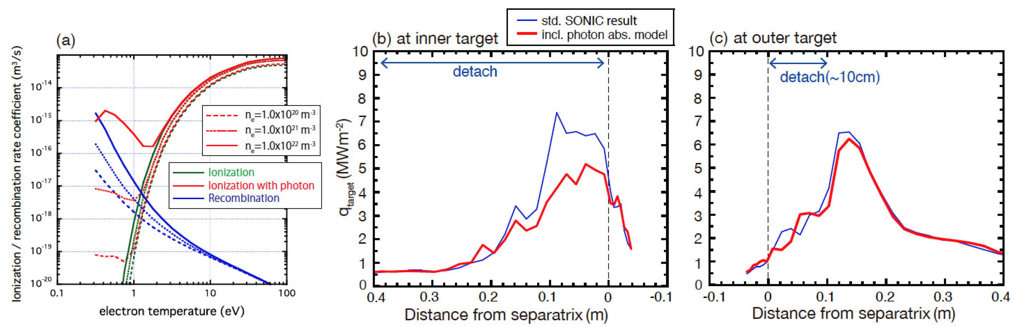
4.2. Development of Photon Transport Model and Its Effect of Plasma Detachment

Under the detached condition of the DEMO divertor, i.e. high neutral density and large divertor size, photon absorption of Lyman and Balmer line radiations by neutral atoms will enhance the ionization process and change the distribution of the detached plasma. Plasma density becomes significantly high, such as a few 1021 m−3, as shown in Figure 3. Typical optical pass length of Ly-α is decreased to ~1 mm, and ionization process is enhanced locally by the photon absorption. A local photon transport model is based on collisional radiative (CR) model calculation of neutral atom [51] and assumes photon absorption in the small optical pass (2 mm radius sphere from the photon source), where a database of effective ionization rate-coefficient is determined as a function of ne, Te, neutral density (n0), temperature (T0) and molecule density. With considering the photon absorption process, an effective ionization rate coefficient is enhanced in low Te (≤1–2 eV) and high (ne ≥ 1021 m−3) plasma when compared to the recombination rate, as shown in Figure 9a. Therefore, profiles of nediv and Tediv in the detached divertor will be modified. A self-consistent iterative calculation of the photon transport model and the SONIC code was carried out for the SlimCS DEMO inner divertor [52], where the plasma density was significantly high up to several 1021 m−3, and volume and surface recombination processes contributed to the divertor heat load.
Self-consistent photon transport simulation was also performed for the JA DEMO divertor as shown in Figure 3, where the maximum nediv is lower and Tediv is comparable to those for the SlimCS DEMO divertor. Larger effects were mainly seen in wide region of the inner divertor; the target heat load decreased by 20% near the separatrix and 30% at the peak qtarget location, as shown in Figure 9b. This was explained by decreasing Tediv and increasing nediv, due to enhancement of the ionization by the photon excitation. At the same time, n0 at the target (n0div) and pumping particle flux in the divertor were reduced. Similar effects were also observed in the outer divertor as shown in Figure 9c; reduction of the target heat load was less than 10% near the peak qtarget location due to lower nediv of ~1.5 × 10²⁰ m−3. As a result, for the DEMO-level power and particle handling, energy transport accompanying with the photo-excitation will significantly affect the evaluation of the heat load profile in the fully detached divertor and very high nediv (≥ a few 1021 m−3) as well as the plasma profile.

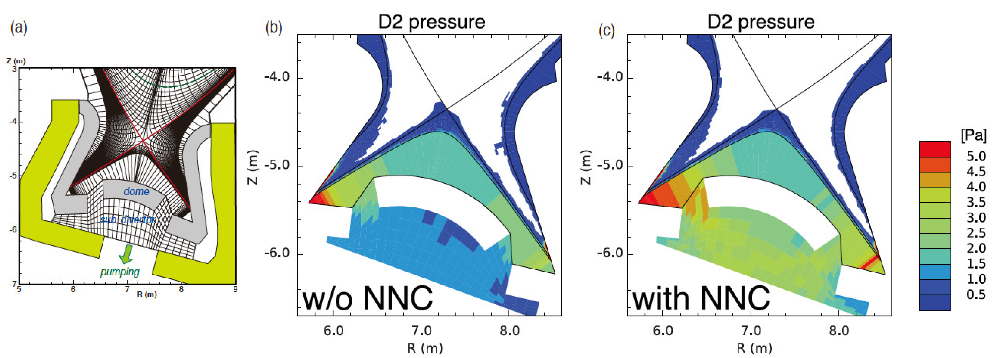
4.3. Neutral-Neutral Elastic Scattering Effect on Detachment and Neutral Pressure

In the NEUT2D code, tracking of a neutral particle (D0) after either charge-exchange reaction or elastic scattering with an ion is calculated with selecting a new velocity, as explained in Reference [2]. A molecular particle (D2) is generated with a small probability of D0 particles incidental to the vessel wall and target, and it is also traced with the same technique with considering dissociation and ionization processes with electron and elastic scattering with ion.
In the high-recycling and detached divertor conditions, neutral–neutral elastic scattering (NNC) plays an important role for the neutral and molecular distributions, the particle exhaust rate and the resultant detachment formation. An NNC model was implicated in the NEUT2D code on the basis of the latest NNC cross-section database, where collision rates and momentum exchange rates were evaluated from differential cross-section database for D0-D0, D0-D2 by Krstic [53] and D2-D2 by Phelps [54]. The NNC model is a rather theoretical expression when compared to those used in EIRENE [55]. The preliminary result shows that neutral pressure in the sub-divertor region is increased by a factor of two to three, as shown in Figure 10. Here, exhaust port from the sub-divertor was located under the dome in this simulation case. The mean-free-path of neutrals is decreased to 0.01–0.1 m, where molecular transport can be treated as the transient regime between the molecular flow and the viscous flow. Neutral pressure in the sub-divertor region significantly affects the engineering design of the particle and He exhaust system. The NNC model was not used in the power exhaust study since the benchmarking with the other neutral transport code such as EIRENE and DEGAS was not done, and it requires large resources. Calculation speed should be increased to handle two species in the MC calculation.

5. Conclusions: Progress Summary

An integrated divertor simulation code, SONIC, has been developed in order to predict self-consistent transport solution of the plasma, neutral and impurities in the SOL and divertor. The SONIC code has been applied for analysis of experiment results in JT-60U and design studies of JT-60SA. It has also applied to Japanese DEMO divertor designs for SlimCS and JA DEMO. While the roll-over of the ion flux and plasma pressure was reproduced at the onset of the plasma detachment, further developments of the plasma and neutral transport modeling are still necessary to quantitatively simulate the divertor detachment. Since the detached divertor operation is a crucial for the DEMO rector design, recent version of the SONIC were used for the divertor design for the DEMO operation scenario. This paper summarized applications of the SONIC code to the JA DEMO divertor design study and recent major achievements.
A new framework of MPMD approach and an MPI data exchange scheme was developed for SONIC code (version 4), which is suitable for multi-author code development. This SONIC revision contributed particularly to improve performance of multiple impurity calculations by IMPMC codes. In addition, an acceleration technique of “backflow model” was incorporated to save computer resource for the impurity atom transport in the sub-divertor.
  • Divertor design and reference operation scenarios for JA DEMO were determined
JA DEMO divertor had a power handling of Psep = 230–290 MW and the power handling parameter of Psep/Rp = 27–34 MWm−1, corresponding to levels two times larger than that of ITER. While the JA DEMO divertor covers all divertor volumes below the X-point based on the ITER divertor, a longer leg length (1.6 m) was chosen to obtain compression of neutral particles and efficient formation of the plasma detachment under the low density and high temperature SOL plasma condition. The SONIC code has been used to evaluate the heat load and the divertor plasma for the two power exhaust scenarios, i.e., Psep ~283 MW for JA DEMO 2014 design and Psep~235 MW for JA DEMO with higher-κ plasma design. Ar seeding was used as a reference impurity, and series of nesep scan solutions were obtained for the reference divertor radiation fraction of f*raddiv ~0.8. The primary requirement of the divertor operation (peak qtarget ≤ 10 MWm−2) was satisfied in the low nesep range of 2 – 3 × 10¹⁹m−3, while the lower Psep scenario had larger heat load margin.
  • Effect of SOL heat flux profile on the partial detachment in the divertor was clarified
Large q// near the separatrix (“near-SOL”) was significantly reduced in the divertor due to large radiation loss and detachment, and the peak qtarget at the outer divertor appeared at the boundary of attached plasma region in the partial detachment. The simulation showed ion convective transport from the outer divertor to SOL (“flow reversal”) near the separatrix, which did not contribute to the ion heat flux towards the outer divertor and produced a “shoulder” in the q//iXp profile. Therefore, the total q//eXp + q//iXp profile had 1.2–1.6 times larger e-folding length in “near-SOL”. The flow reversal also reduced the impurity retention in the outer divertor, which may sustain the attached plasma region and produce the partial detachment.
Since the flow reversal from the outer divertor target was not found in the major tokamak experiments, i.e., it was measured to the target (forward) direction near the X-point, further studies of modeling and experiment are necessary even in existing devices.
  • Operation boundary of JA DEMO divertor was clarified for key power exhaust parameters
Severe case studies of reducing f*raddiv to ~0.7 or/and diffusion coefficients to the half values showed that width of the partial detachment was decreased and the peak qtarget was increased with increasing the local Tidiv and Tediv, accompanied by shifting the flow reversal peak toward the separatrix. Case studies of f*raddiv ~0.7 showed that higher nesep operations such as those larger than 2.6 × 10¹⁹ and 2.3 × 10¹⁹ m−3 were required for the JA DEMO 2014 and JA DEMO with higher-κ scenarios, respectively. For the smaller χ and D cases, the influence of reducing f*raddiv ~0.7 was significantly seen both in the peak qtarget and nesep, i.e., qtarget was increased to larger than 10 MWm−2 and nesep also increased, and the divertor operation expected at nesep higher than ~3 × 10¹⁹ m−3.
Consequently, the proposed divertor geometry and reference power exhaust parameters (Psep = 230–290 MW, f*rad ~0.8, χ = 1 m2s−1, D = 0.3 m2s−1 and nesep = 2 – 3 × 10¹⁹ m−3) were so far consistent with the JA DEMO design concepts. Severe case studies showed margins from the reference parameters, and higher nesep operation is preferable if a severe parameter is required.
Further improvements of the divertor geometry and operation options such as different seeding impurity will be necessary to extend the partial detachment width and to reduce local Tediv and Tidiv at the attached plasma region. Feasible guidelines of the diffusion coefficient profile over the main plasma edge, near-SOL and far-SOL will be demanded to determine the divertor operation window for the DEMO design.
  • Physics models for divertor simulation were evaluated in DEMO SOL and divertor conditions
Three physics models have been investigated in the SONIC code, and influences on the divertor performance were evaluated under the DEMO SOL and divertor conditions; Further validations of simulation models will be required to be incorporated as defaults.
(i)
A kinetic model for the thermal force (TF) on impurity ions was evaluated for high temperature and low collisionality SOL plasma. The revised model affected to reduce both the TF on impurity transport and local accumulation peaks of cArdiv under the low collisionality SOL condition. It also reduced Pradsol, but the value was relatively small.
(ii)
Photon transport model showed that energy transport accompanying the photo-absorption/excitation significantly affected the evaluation of the heat load and the plasma profiles in the fully detached divertor under the DEMO-level high density condition (nediv ≥ a few 1021 m−3).
(iii)
The neutral–neutral collision (NNC) model was implicated since neutral–neutral elastic scattering plays an important role for distributions of neutrals and molecules, and detachment plasma. The preliminary result shows that neutral pressure in the sub-divertor region is increased by a factor of two to three, which significantly affects engineering design of the particle and He exhaust system.

Author Contributions

Conceptualization, N.A. and K.H.; methodology, K.H.; software, N.A., K.H. and Y.H.; formal analysis, N.A.; investigation, N.A.; resources, Joint Special Design Team for Fusion DEMO; writing—original draft preparation, N.A.; writing—review and editing, N.A. and K.H.; project administration, Y.S.; funding acquisition, Joint Special Design Team for Fusion DEMO. All authors have read and agreed to the published version of the manuscript.

Funding

This research received no external funding.

Data Availability Statement

Not applicable.

Acknowledgments

This work was carried out within the framework of the Broader Approach DEMO Design Activity, using the JFRS-1 supercomputer system at CSC, IFERC, Rokkasho. Authors would like to thank continuous supports by Joint Special Design Team for Fusion DEMO. Authors also thank to K. Sawada for providing basic model of photon transport processes, and to S. Tokunaga for providing a part of database of NNC cross-section.

Conflicts of Interest

The authors declare no conflict of interest.

References

  1. Shimizu, K.; Takizuka, T.; Sakurai, S.; Tamai, H.; Takenaga, H.; Kubo, H.; Miura, Y. Simulation of divertor detachment characteristics in JT-60 with superconducting coils. J. Nucl. Mater. 2003, 313, 1277–1281. [Google Scholar] [CrossRef]
  2. Kawashima, H.; Shimizu, K.; Takizuka, T.; Sakurai, S.; Nakano, T.; Asakura, N.; Ozeki, T. Development of Integrated SOL/Divertor Code and Simulation Study in JAEA. J. Plasma Fusion Res. 2006, 1, 31. [Google Scholar] [CrossRef] [Green Version]
  3. Braams, B. A Multi-Fluid Code for Simulation of the Edge Plasma in Tokamaks. NET Report EUR-FU IXII-80-87-68. Comm. of the European Communities. 1987. Available online: http://www.eirene.de/Braams-NET-report.pdf (accessed on 1 February 2022).
  4. Heifetz, D.B.; Post, D.; Petravic, M.; Wetsheit, J.; Bateman, G. A Monte-Carlo Model of Neutral-Particle Transport in Diverted Plasmas. J. Comp. Phys. 1982, 46, 309–327. [Google Scholar] [CrossRef] [Green Version]
  5. Heifetz, D.B. Physics of Plasma-Wall Interactions in Controlled Fusion; Post, D.E., Behrisch, R., Eds.; Plenum Press: New York, NY, USA; London, UK, 1986; p. 695. [Google Scholar]
  6. Shimizu, K.; Kubo, H.; Takizuka, T.; Azumi, M.; Shimada, M.; Tsuji, S.; Hosogane, N.; Sugie, T.; Sakasai, A.; Asakura, N.; et al. Impurity transport modelling and simulation analysis of impurity behavior in JT-60U. J. Nucl. Mater. 1995, 220, 410–414. [Google Scholar] [CrossRef]
  7. Shimizu, K.; Takizuka, T.; Sakasai, A. A review on impurity transport in divertors. J. Nucl. Mater. 1997, 241, 167–181. [Google Scholar] [CrossRef]
  8. Shimizu, K.; Takizuka, T.; Kawashima, H. Kinetic modelling of impurity transport in detached plasma for integrated divertor simulation with SONIC (SOLDOR/NEUT2D/IMPMC/EDDY). Nucl. Fusion 2009, 49, 065028. [Google Scholar] [CrossRef]
  9. Konoshima, S.; Tamai, H.; Miura, Y.; Higashijima, S.; Kubo, H.; Sakurai, S.; Shimizu, K.; Takizuka, T.; Koide, Y.; Hatae, T.; et al. Two-dimensional distribution of divertor radiation in JT-60U. J. Nucl. Mater. 2003, 313, 888–892. [Google Scholar] [CrossRef]
  10. Kawashima, H.; Shimizu, K.; Takizuka, T.; Sakurai, S.; Nakano, T.; Asakura, N.; Ozeki, T. Analysis of Particle Pumping Using SOLDOR/NEUT2D Code in the JT-60U Tokamak. Contrib. Plasma Phys. 2008, 48, 158–163. [Google Scholar] [CrossRef]
  11. Hoshino, K.; Shimizu, K.; Takizuka, T.; Asakura, N.; Nakano, T. Modelling of JT-60U Detached Divertor Plasma using SONIC code. J. Plasma Fusion Res. 2010, 9, 592–597. [Google Scholar]
  12. Hoshino, K.; Shimizu, K.; Takizuka, T.; Asakura, N.; Nakano, T. Improvement of the detachment modelling in the SONIC simulation. J. Nucl. Mater. 2011, 415, S549–S552. [Google Scholar] [CrossRef]
  13. Hoshino, K.; Shimizu, K.; Takizuka, T.; Asakura, N.; Nakano, T. The influence of the radial particle transport on the divertor plasma detachment. J. Nucl. Mater. 2015, 463, 573–576. [Google Scholar] [CrossRef]
  14. Asakura, N.; Kawashima, H.; Shimizu, K.; Sakurai, S.; Fujita, T.; Takenaga, H.; Nakano, T.; Kubo, H.; Higashijima, S.; Hayashi, T.; et al. Development of Integrated SOL/Divertor Code and Simulation Study in JAEA. In Proceedings of the 34th European Physical Society Conference Plasma Physics Controlled Fusion, Warsawa, Poland, 2–6 July 2007. [Google Scholar]
  15. Kawashima, H.; Shimizu, K.; Takizuka, T.; Asakura, N.; Sakurai, S.; Matsukawa, M.; Fujita, T. Design study of JT-60SA divertor for high heat and particle controllability. Fusion Eng. Des. 2008, 83, 1643–1647. [Google Scholar] [CrossRef]
  16. Shimizu, K.; Takizuka, T.; Kawashima, H. Kinetic effect of thermal force on impurity transport: Simulation of JT-60SA divertor with integrated divertor code SONIC. J. Nucl. Mater. 2009, 390, 307–310. [Google Scholar] [CrossRef]
  17. Kawashima, H.; Hoshino, K.; Shimizu, K.; Takizuka, T.; Ide, S.; Sakurai, S.; Asakura, N. Evaluation of heat and particle controllability on the JT-60SA divertor. J. Nucl. Mater. 2011, 415, S948–S951. [Google Scholar] [CrossRef]
  18. Hoshino, K.; Shimizu, K.; Kawashima, H.; Takizuka, T.; Nakano, T.; Ide, S. Development of the Backflow Model for Simplified Impurity Exhaust in Monte-Carlo Calculation. Contr. Plasma Phys. 2014, 54, 404–408. [Google Scholar] [CrossRef]
  19. Kawashima, H.; Shimizu, K.; Hoshino, K.; Nakano, T.; Asakura, N. Simulation of radiative divertor plasmas by Ar seeding with the full W-wall in JT-60SA. Contr. Plasma Phys. 2016, 56, 778–783. [Google Scholar] [CrossRef]
  20. Hoshino, K.; Homma, Y.; Tokunaga, S.; Shimizu, K. Multi-impurity divertor simulation using a Monte Carlo kinetic impurity transport model. Contr. Plasma Phys. 2018, 58, 638–642. [Google Scholar] [CrossRef]
  21. Yamoto, S.; Hoshino, K.; Homma, Y.; Nakano, T.; Hayashi, N. Simulation study of mixed-impurity seeding with extension of integrated divertor code SONIC. Plasma Phys. Control. Fusion 2020, 62, 045006. [Google Scholar] [CrossRef]
  22. Yamoto, S.; Hoshino, K.; Homma, Y.; Nakano, T.; Hayashi, N. Study of multiple impurity seeding effect using SONIC integrated divertor code for JT-60SA plasma prediction. Contr. Plasma Phys. 2020, 60, e201900146. [Google Scholar] [CrossRef]
  23. Groth, M.; Brezinsek, S.; Belo, P.; Beurskens, M.N.A.; Brix, M.; Clever, M.; Coenen, J.W.; Corrigan, C.; Eich, T.; Flanagan, J.; et al. Impact of carbon and tungsten as divertor materials on the scrape-off layer conditions in JET. Nucl. Fusion 2013, 53, 093016. [Google Scholar] [CrossRef]
  24. Pitts, R.A.; Bonnin, X.; Escourbiac, F.; Frerichs, H.; Gunn, J.P.; Hirai, T.; Kukushkin, A.S.; Kaveeva, E.; Miller, M.A.; Moulton, D.; et al. Physics basis for the first ITER tungsten divertor. Nucl. Meter. Energy 2019, 20, 100696. [Google Scholar] [CrossRef]
  25. Kaveeva, E.; Rozhansky, V.; Senichenkov, I.; Sytova, E.; Veselova, I.; Voskoboynikov, S.; Bonnin, X.; Pitts, R.A.; Kukushkin, A.S.; Wiesen, S.; et al. SOLPS-ITER modelling of ITER edge plasma with drifts and currents. Nucl. Fusion 2020, 60, 046019. [Google Scholar] [CrossRef]
  26. Coster, D.P.; Bonnin, X.; Braams, B.; Buerbaumer, H.; Kaveeva, E.; Kim, J.-W.; Kukushkin, A.; Nishimura, Y.; Reiter, D.; Rozhansky, V.; et al. Further Developments of the Edge Transport Simulation Package, SOLPS. In Proceedings of the 19th International Conference on Fusion Energy, Lyon, France, 14–19 October 2002. [Google Scholar]
  27. Tobita, K.; Nishio, S.; Enoeda, M.; Kawashima, H.; Kurita, G.; Tanigawa, H.; Nakamura, H.; Honda, M.; Saito, A.; Sato, S.; et al. Compact DEMO, SlimCS: Design progress and issues. Nucl. Fusion 2009, 49, 075029. [Google Scholar] [CrossRef]
  28. Asakura, N.; Shimizu, K.; Hoshino, K.; Tobita, K.; Tokunaga, S.; Takizuka, T. A simulation study of large power handling in the divertor for a Demo reactor. Nucl. Fusion 2013, 53, 123013. [Google Scholar] [CrossRef]
  29. Sakamoto, Y.; Tobita, K.; Utoh, H.; Asakura, N.; Someya, Y.; Hoshino, K.; Nakamura, M.; Tokunaga, S.; the DEMO Design Team. DEMO Concept Development and Assessment of Relevant Technologies. In Proceedings of the 25th IAEA International Conference on Fusion Energy, St. Petersburg, Russia, 13–18 October 2014. [Google Scholar]
  30. Tobita, K.; Asakura, N.; Hiwatari, R.; Someya, Y.; Utoh, H.; Katayam, K.; Nishimura, A.; Sakamoto, Y.; Homma, Y.; Kudo, H.; et al. Design Strategy and Recent Design Activity on Japan’s DEMO. Fusion Sci. Technol. 2017, 72, 537–545. [Google Scholar] [CrossRef]
  31. Asakura, N.; Hoshino, K.; Suzuki, S.; Tokunaga, S.; Someya, Y.; Utoh, H.; Kudo, H.; Sakamoto, Y.; Hiwatari, R.; Tobita, K.; et al. Studies of power exhaust and divertor design for a 1.5 GW-level fusion power DEMO. Nucl. Fusion 2017, 57, 126050. [Google Scholar] [CrossRef]
  32. Wenninger, R.; Arbeiter, F.; Aubert, J.; Aho-Mantila, L.; Albanese, R.; Ambrosino, R.; Angioni, C.; Artaud, J.-F.; Bernert, M.; Fable, E.; et al. Advances in the physics basis for the European DEMO design. Nucl. Fusion 2015, 55, 063003. [Google Scholar] [CrossRef]
  33. ITER Physics Basis Expert Groups on Confinement and Transport and Confinement Modelling and Database, ITER Physics Basis Editor. Nucl. Fusion 1999, 39, 2175–2250.
  34. Kawashima, H.; Shimizu, K.; Takizuka, T.; Tobita, K.; Nishio, S.; Sakurai, S.; Takenaga, H. Simulation study for divertor design to handle huge exhaust power in the SlimCS DEMO reactor. Nucl. Fusion 2009, 49, 065007. [Google Scholar] [CrossRef]
  35. Asakura, N.; Shimizu, K.; Kawashima, H.; Tobita, K.; Takizuka, T. Simulation of Power Exhaust in Edge and Divertor of the SlimCS Tokamak Demo Reactor. J. Plasma Fusion Res. Ser. 2010, 9, 136–141. [Google Scholar]
  36. Hoshino, K.; Shimizu, K.; Asakura, N.; Takizuka, T.; Nakamura, M.; Tobita, K. Simulation Study of an Extended Divertor Leg for Heat Control in the SlimCS DEMO Reactor. Contrib. Plasma Phys. 2012, 52, 550–554. [Google Scholar] [CrossRef]
  37. Hoshino, K.; Asakura, N.; Shimizu, K.K.; Tokunaga, S.; Takizuka, T.; Someya, Y.; Nakamura, M.; Utoh, H.; Sakamoto, Y.; Tobita, K. Divertor Study on DEMO Reactor. Plasma Fusion Res. 2014, 9, 3403070. [Google Scholar] [CrossRef]
  38. Asakura, N.; Hoshino, K.; Homma, Y.; Sakamoto, Y. Joint Special Design Team for Fusion DEMO Simulation studies of divertor detachment and critical power exhaust parameters for Japanese DEMO design. Nucl. Mater. Energy 2021, 26, 100864. [Google Scholar] [CrossRef]
  39. Kukushkin, A.; Pacher, H.D.; Pacher, G.W.; Kotov, V.; Pitts, R.A.; Reiter, D. Consequences of a reduction of the upstream power SOL width in ITER. J. Nucl. Mater. 2013, 438, S203–S207. [Google Scholar] [CrossRef]
  40. Loarte, A.; Lipschultz, B.; Kukushkin, A.S.; Matthews, G.F.; Stangeby, P.C.; Asakura, N.; Counsell, G.F.; Federici, G.; Kallenbach, A.; Krieger, K.; et al. Progress in the ITER Physics Basis Chapter 4: Power and particle control. Nucl. Fusion 2007, 47, S203–S263. [Google Scholar] [CrossRef] [Green Version]
  41. Subba, F.; Coster, D.P.; Moscheni, M.; Siccinio, M. SOLPS-ITER modeling of divertor scenarios for EU-DEMO. Nucl. Fusion 2021, 61, 106013. [Google Scholar] [CrossRef]
  42. Asakura, N.; Hoshino, K.; Kakudate, S.; Subba, F.; Vorpahl, C.; Homma, Y.; Utoh, H.; Someya, Y.; Sakamoto, Y.; Hiwatari, R.; et al. Power Exhaust Concepts and Divertor Designs for Japanese and European DEMO Fusion Reactors. Nucl. Fusion 2021, 61, 126057. [Google Scholar] [CrossRef]
  43. Kallenbach, A.; Asakura, N.; Kirk, A.; Korotkov, A.; Mahdavi, M.A.; Mossessian, D.; Porter, G.D. Multi-machine comparisons of H-mode separatrix densities and edge profile behaviour in the ITPA SOL and Divertor Physics Topical Group. J. Nucl. Mater. 2005, 337, 381–385. [Google Scholar] [CrossRef]
  44. Leonard, A.W.; McLean, A.G.; Makowski, M.A.; Stangeby, P.C. Compatibility of separatrix density scaling for divertor detachment with H-mode pedestal operation in DIII-D. Nucl. Fusion 2017, 57, 086033. [Google Scholar] [CrossRef]
  45. Eich, T.; Goldston, R.J.; Kallenbach, A.; Sieglin, B.; Sun, H.J. ASDEX Upgrade Team; JET Contributors; Correlation of the tokamak H-mode density limit with ballooning stability at the separatrix. Nucl. Fusion 2018, 58, 034001. [Google Scholar] [CrossRef] [Green Version]
  46. Krasheninnikov, S.I. Reverse flow and parameter profiles in a dense tokamak divertor plasma. Nucl. Fusion 1992, 32, 1927–1934. [Google Scholar] [CrossRef]
  47. Eich, T.; Leonard, A.W.; Pitts, R.A.; Fundamenski, W.; Goldston, R.J.; Gray, T.K.; Herrmann, A.; Kirk, A.; Kallenbach, A. Scaling of the tokamak near the scrape-off layer H-mode power width and implications for ITER. Nucl. Fusion 2013, 53, 093031. [Google Scholar] [CrossRef]
  48. Reiser, D.; Reiter, D.; Tokar, M.Z. Improved kinetic test particle model for impurity transport in tokamaks. Nucl. Fusion 1998, 38, 165–177. [Google Scholar] [CrossRef]
  49. Homma, Y.; Hoshino, K.; Tokunaga, S.; Yamoto, S.; Hatayama, A.; Asakura, N.; Sakamoto, Y.; Tobita, K. Joint Special Design Team for Fusion DEMO An extended kinetic model for the thermal force on impurity particles in weakly collisional plasmas. Contrib. Plasma Phys. 2018, 58, 629–637. [Google Scholar] [CrossRef]
  50. Homma, Y.; Hoshino, K.; Yamoto, S.; Tokunaga, S.; Asakura, N.; Sakamoto, Y. Joint Special Design Team for Fusion DEMO Effect of collisionality dependence of thermal force on impurity transport under a lower collisional condition in DEMO scrape-off layer plasma. Nucl. Fusion 2020, 60, 046031. [Google Scholar] [CrossRef]
  51. Sawada, K. Iterative numerical method for the inclusion of radiation trapping into a collisional-radiative model. J. Plasma Phys. 2006, 72, 1025–1029. [Google Scholar] [CrossRef]
  52. Hoshino, K.; Sawada, K.; Idei, R.; Tokunaga, S.; Asakura, N.; Shimizu, K.; Ohno, N. Photon Trapping Effects in DEMO Divertor Plasma. Contrib. Plasma Phys. 2016, 56, 657–662. [Google Scholar] [CrossRef]
  53. Krstic, P.; Schultz, D. Elastic and Related Transport Cross Sections for Collisions among Isotopomers of H++H, H++H2, H++He, H+H, and H+H2. At. Plasma-Mater. Data Fusion 1998, 8, 1–689. [Google Scholar]
  54. Phelps, A.V. Cross Sections and Swarm Coefficients for H+, H2+, H3+, H, H2, and H in H2 for Energies from 0.1 eV to 10 keV. J. Phys. Chem. Ref. Data 1990, 19, 653. [Google Scholar] [CrossRef] [Green Version]
  55. Reiter, D.; May, C.; Baelmans, M.; Börner, P. Non-linear effects on neutral gas transport in divertors. J. Nucl. Mater. 1997, 241, 342–348. [Google Scholar] [CrossRef]
Figure 1. (a) Restructured SONIC code with Multiple-Program Multiple-Data (MPMD) framework, (b) Improved numerical efficiency for multi-impurity calculation of SONIC code with MPMD framework.
Processes 10 00872 g001
Figure 2. Simulation mesh for SONIC calculation. (a) All scrape-off layer (SOL) plasma regions and geometry of first wall and divertor are shown. Fuel gas is injected just below the plasma midplane. (b) Enlarged divertor region. Exhausted power (Pout) and particle (Γout) are given at the core-edge boundary (rmid/ap = 0.95). Ar is injected at the outer divertor above the SOL plasma region. [38] (c) Ar exhaust fluxes at the inner and outer divertor slots (Γexin and Γexout) and Ar backflow fluxes (Γbkin and Γbkout) are calculated once in every 10 IMPMC runs. In the following 9 IMPMC runs, Γbkin and Γbkout are provided proportional to ΓpuffAr in “backflow model”.
Processes 10 00872 g002
Figure 3. (a,b) Distributions of Ar radiation power density (Wrad) in the inner and outer divertors, respectively: nesep = 2.0 × 10¹⁹ m−3, Pout = 250 MW and Pradedge + Pradsol + Praddiv = 200 MW. Profiles of (c,d) nediv, Tediv and Tidiv, (e,f) integrating heat load components at the inner and outer divertor target, respectively [38].
Processes 10 00872 g003
Figure 4. Distributions of (a) Te, (b) Wrad, (c) cAr, (d) Mach number of the plasma flow, (e) static plasma pressure (neTe + niTi) and (f) total plasma pressure (neTe + niTi + miniVi2), along three representative field lines, corresponding to the 2nd, 6th and 9th radial meshes outside the separatrix. Triangle corresponds to each field line location near the X-point. Positive Mach number represents the flow direction toward the outer target. The plasma detachment is produced near the target in the former two field lines, and the peak qtarget is seen at the target (attached plasma) in the third one.
Processes 10 00872 g004
Figure 5. Profiles of (a) Te and Ti at the outer divertor target and near the X-point, (b) plasma static pressure and total plasma pressure including the dynamic one at the outer divertor and near the X-point, (c) electron and total parallel heat fluxes near the X-point (q//eXp, q//eXp + q//iXp) and the heat load at the outer target. Distances from the separatrix at the outer target and near the X-point are mapped to the outer midplane SOL radius.
Processes 10 00872 g005
Figure 6. (a,c) Mach number profile of the parallel plasma flow in SOL near the X-point, and (b,d) electron, ion and total parallel heat flux profiles (q//eXp, q//iXp, q//eXp + q//iXp) for standard χ and D case (1.0 and 0.3 m2s−1) and smaller cases (0.5 and 0.15 m2s−1), respectively. Distance from the separatrix near X-point is mapped to the midplane SOL radius. (e) λq//near for four different input parameter cases (Pout = 250 and 300 MW, fradin = 0.7 and 0.8) for the standard (circles) and smaller (squires) diffusion coefficients. Case-1 is shown by open circles.
Processes 10 00872 g006
Figure 7. Profiles of (a) Tediv, Tidiv and nediv, (b) qtarget and integrating heat load components at the outer target for JA DEMO higher-κ with Psep ~235 MW and f*raddiv ~0.66. Four series of peak qtarget for given Psep and f*raddiv as a function of nesep. (c) Different closed symbols show four cases with standard χe = χi = 1 m2s−1 and D = 0.3 m2s−1, (d) open symbols show corresponding four results with reducing χ e = χi = 0.5 m2s−1 and D = 0.15 m2s−1. Four guidelines correspond to results with standard χ and D [42].
Processes 10 00872 g007
Figure 8. (a)Distribution of impurity concentration (cAr) along the magnetic flux tube near the separatrix. The dotted, thin-solid blue and bold-solid red line correspond to case A (conventional model), B (revised model with given BG plasma parameters) and C (self-consistent calculation), respectively. (b) Distribution of impurity radiation power density Prad = nenZLZ(Te) MWm−3 along the magnetic flux line. The dotted and bold-solid red line correspond to case A and C, respectively. [50].
Processes 10 00872 g008
Figure 9. (a) Effective ionization rate coefficient without and with the photon trapping for neutral temperature (T0 = 1 eV) and density (n0 = 1020 m−3) and the three electron density cases [52]. Simulation for JA DEMO: total target heat load profiles at (b) inner and (c) outer divertors with and without photon transport model.
Processes 10 00872 g009
Figure 10. (a) Divertor geometry, pumping port and calculation mesh (2016 design) for SONIC simulation. Deuterium gas pressure distributions in the divertor, (b) without and (c) with NNC effect.
Processes 10 00872 g010
Publisher’s Note: MDPI stays neutral with regard to jurisdictional claims in published maps and institutional affiliations.

