Article

Parameter Optimization and Experimental Study of Jet Mixing Device Based on CFD

State Key Laboratory of Mining Response and Disaster Prevention and Control in Deep Coal Mines, College of Materials Science and Engineering, Anhui University of Science and Technology, Huainan 232001, China
*
Author to whom correspondence should be addressed.
Processes 2022, 10(5), 933; https://doi.org/10.3390/pr10050933
Submission received: 5 April 2022 / Revised: 27 April 2022 / Accepted: 6 May 2022 / Published: 8 May 2022

Abstract

:
The parameters of jet mixing devices have an important influence on the mixing process, particle movement and interface regulation. At present, jet mixing devices are widely used in the coal slime flotation field, and their variable parameters lack systematic optimization. In this paper, the performance of reagent mixing and the distribution characteristics of flow field are taken as the evaluation indexes, and computational fluid dynamics (CFD) software (FLUENT) is used to optimize the variable parameters of the device. The results show that when the area ratio A r = 1.96 ~ 3.24 , the throat-nozzle distance L e = 0.2 D h ~ 0.6 D h , the suction tube is located 1/4~1/2 L z to the left of the nozzle outlet and is symmetrically arranged, the length of the throat tube L is from 6 D z to 12 D z , the mixing performance of the jet mixing device was optimal. The flow field distribution characteristics showed that the area ratio has a more significant effect. The larger the area ratio is, the more favorable the mixing of the working fluid and the injection fluid is. The throat-nozzle distance has little effect on the flow field distribution, and its optimal value ranges from 0.3 D h to 0.6 D h . The fog droplet size test showed that the dispersion effect was the best when the area ratio A r = 3.24 . The diameter size test of the injected bubbles was carried out to verify the performance of the jet mixing device after parameter optimization. The experimental results and the simulation results confirm each other, which proves the correctness of the numerical simulation results.

1. Introduction

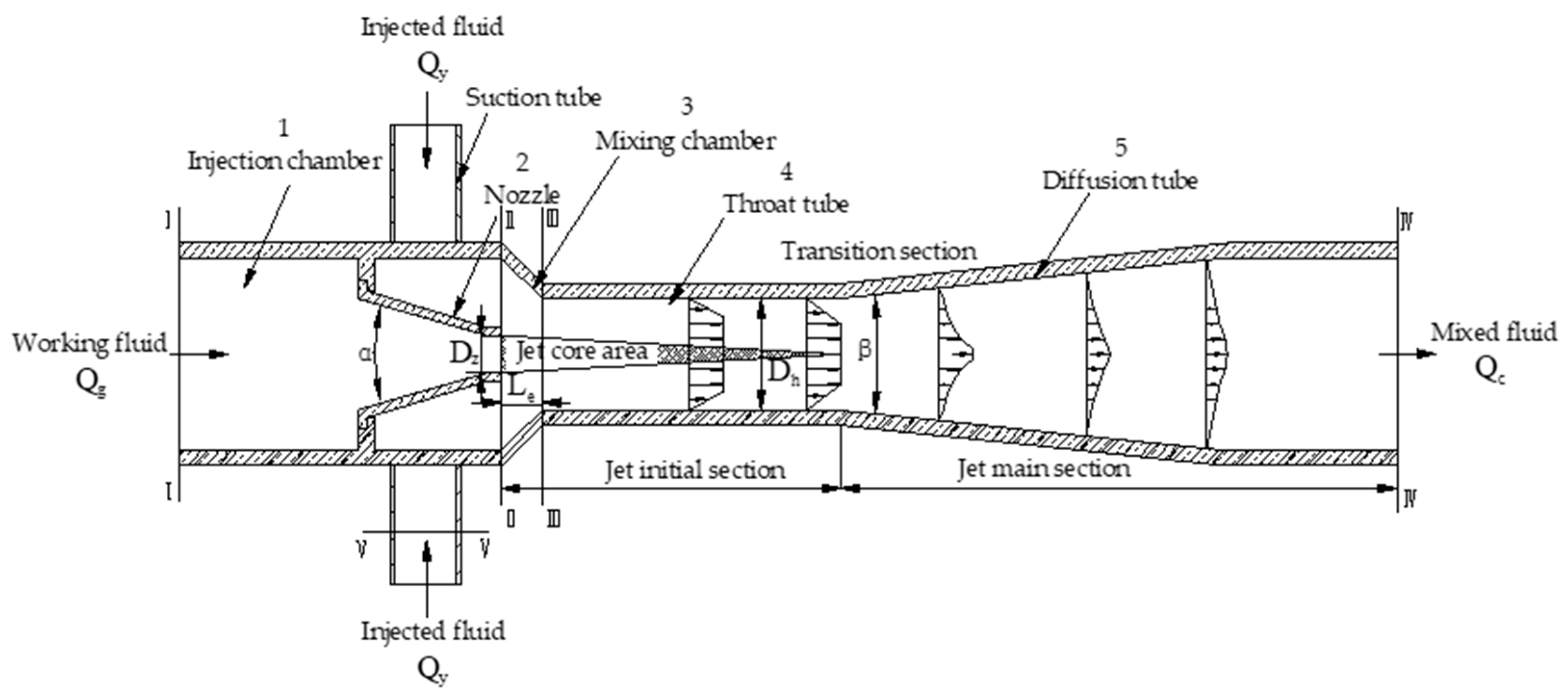
Flotation is the most widely used and effective separation method for fine particle materials. In recent years, jet mixing technology has been applied to every link of the flotation process [1,2], such as the micro-bubble generator of the swirl micro-bubble flotation column [3,4,5,6], the pneumatic stirring device of jet flotation machine [7,8,9], and the reagent mixing device of jet slurry adjuster [10,11]. The current research focuses on the optimization of structural parameters, flow field analysis and mixing process of reagents and working fluids. Ni et al. [12] studied the effect of a self-aspirated bubble generator on the flotation of coarse coal particles. The recovery of coarse coal particles using a flotation column can be improved by adding a self-aspirated bubble generator into the feed pipe. Li et al. [13] used FLUENT software to simulate the gas-liquid two-phase flow inside a self-absorbing microbubble generatorto, and the effect of area ratio, a key structural parameter, was studied in detail. Wang et al. [14] carried out a numerical simulation on the three-dimensional flow field of a micro-bubble generator with different throat-nozzle distances and studied the influence of throat-nozzle distances on airflow, bubble diameter and distribution. Finally, the range of parameters conducive to fine mineral flotation was obtained. Yang et al. [15] designed a jet flotation column and simulated the flow field distribution in the jet aeration device, based on the standard k-ε turbulent mixing model and the multiphase flow model. In addition, the simulation results can help to optimize the structure of the jet flotation column. Taşdemir et al. [16] studied the effect of jet length and jet velocity on the recovery rate of different particle size products in the Jameson flotation machine. An increase in jet length, jet velocity and holdup results in the recovery improvement for fine particles and loss of recovery for medium/coarse particles. Vondricka et al. [17] used the CFD numerical simulation method to study the distribution characteristics of mixture concentration in the flow field under the condition of different mixture ratios. Xu et al. [18] used FLUENT software to simulate the distribution characteristics of the axial and radial concentration of the mixing tube and studied the influence of the area ratio on the uniformity of mixing. The literature review shows that the parameters of jet mixing devices have an important impact on reagent mixing performance and flow field distribution characteristics, but the variable parameters of jet mixing devices applied in the slime flotation field lack systematic optimization. In this paper, a jet stirring combined device of coal slime floatation and mixing (China Patent, ZL2015108627218) is proposed. The jet-mixing link mainly plays a role in reagent dispersion and mixing, which has an important influence on the performance of the whole device. The mixing performance and internal flow field distribution of the jet mixing device were simulated by FLUENT software; and the parameters of the jet mixing device, such as the area ratio A r ( A r = ( D h D z ) 2   ,   D h is the throat tube diameter, D z is the nozzle diameter), the throat-nozzle distance L e (Distance between nozzle and throat tube entrance), the position and arrangement of suction tube, the length of throat tube L and the nozzle outlet velocity were optimized. The influence of the area ratio on dispersion performance of the reagent was investigated by the droplet diameter test experiment. The diameter size migration law of injected bubbles was explored, which verifies the performance of the jet mixing device after parameter optimization. The experimental results and the simulation results are mutually verified, which provides theoretical guidance for the structure optimization and improvement of jet mixing devices, and is more conducive to the application of jet mixing devices in the field of coal slime flotation.

2. Theoretical Analysis of Jet Mixing Device

2.1. Working Process and Structural Parameters

The structure of the jet stirring combined device of coal slime floatation and mixing is shown in Figure 1. It is mainly composed of a jet mixing device, inclined plate and stirring apparatus. The main function of the jet mixing device is to realize the full mixing of the reagents and coal slurry. The trapezoidal barrier strip is designed on the inclined plate, and the coal slurry jumps and falls continuously through the barrier strip. The coarse particles in the coal slurry move close to the inclined plate and are blocked by the trapezoidal barrier strip, so the mixing time is long, which can promote the particle surface adhesion of sufficient and stable reagents; the fine particles move with the upper coal slurry and the mixing time is short, which avoids excessive reagent adsorption on its surface. The stirring apparatus further realizes the mixing of multiphase particles, while keeping the solid particles suspended in the mixing tank until it flows out from the outlet. The jet mixing device has an important effect on the performance of the whole equipment, and its mixing performance depends on the optimization of the variable parameters.
The structure and working process of the jet mixing device are shown in Figure 2. The working fluid Q g is injected by nozzle 2 at high speed through the injection chamber 1, and negative pressure is generated in mixing chamber 3. The flocculation diffusion generated by the flow beam attracts the injected fluid Q y , and then, the momentum and mass of the two fluids are exchanged in the throat tube 4 and then discharged from the diffusion tube 5. Generally, the jet stream can be divided into the jet initial section and jet main section along the direction of travel. In the jet initial section, there is a jet core area, and the jet velocity simply maintains the nozzle outlet velocity. With the intervention of the injected fluid, the jet boundary gradually widens and the velocity decreases. After the transition section, the jet velocity on the axis begins to weaken when it enters the main section of the jet.
The structural parameters are divided into fixed parameters and variable parameters. The fixed parameters are within the range of optimization values mentioned in the relevant literature [19,20], which are as follows: the nozzle convergence angle α is 15°, the throat tube diffusion angle β is 10°, the throat tube length L is 120 mm, the diffusion tube length is 50 mm, the feeding tube diameter is 30 mm, the diameter of suction tube is 5 mm and the arrangement is symmetrical. The variable parameters are the test parameters that need to be optimized. In this paper, the area ratio A r , the throat-nozzle distance L e and the position of suction tube inlet were taken as the research objects. The change of area ratio is realized by fixing the nozzle diameter D z and changing the throat diameter D h . The position of the suction tube was dynamically arranged along with the mixing chamber. The suction tube was dynamically arranged along the mixing chamber, and then optimized after the area ratio and the nozzle-distance were optimized.
The working fluid enters the jet chamber at the speed of 2 m/s and is ejected from the nozzle at the speed of 18 m/s. Negative pressure is formed in the mixing chamber and the reagent is inhaled. The agent is dispersed under the impact and cutting of the jet action, and after mixing with the working fluid, it is ejected by the diffusion tube.

2.2. Device Performance Evaluation Index

2.2.1. The Ejector Performance

There are many working parameters and structural parameters of the jet mixing device. To describe the mixing characteristics under different working parameters and structural parameters uniformly, the relationship curves between pressure ratio p , flow ratio q , mixing efficiency η and structural parameters are generally used to evaluate the performance of a jet mixing device in engineering.
p = P c P y P g P y
q = Q y Q g
η = p q
where the P g is the total pressure of the working fluid; P y is the total pressure of the driving fluid; P c is the total pressure of the mixed fluid; Q y is the injected fluid; Q g is the working fluid.

2.2.2. The Flow Field Characteristics

The flow field characteristics usually include pressure field characteristics, velocity field characteristics and turbulence intensity characteristics. The static pressure difference in different parts of the jet device can reflect the resistance loss of the pipeline in the device. The velocity field can directly reflect the fluid momentum exchange. The turbulence intensity can reflect coiling mixing intensity to a certain extent.

3. Numerical Simulation Calculation and Test Method

3.1. Model Description and Simulation Parameters

3.1.1. Grid Type and Subdivision Method

Gambit2.4.6 was used for grid division of the model. Hexahedral grid division was adopted for the injection chamber, nozzle, throat tube and diffusion tube, and tetrahedral grid division was adopted for thesuction tube and mixing chamber. The grid spacing is as follows: the grid spacing of the injection chamber and nozzle is 1.0 mm, the grid spacing of the throat tube and diffusion tube is 0.5 mm, the grid spacing of the mixing chamber is 1.2 mm, and the grid spacing of the suction tube is 0.3 mm.

3.1.2. Solver Parameter and Boundary Condition Setting

The volume function method was selected, the second-order upwind scheme was adopted for the discretization of the parameters, such as convection term, and SIMPLEC mode was adopted for the coupling of velocity and pressure, and the convergence accuracy was set to 10 4 . For the multiphase model, the mixture model was selected; the number of Eulerian Phases was set to 2; slip velocity under the mixture parameters option was selected. For the turbulence model, the realizable K -ε model was selected by consulting the applicable scope of each equation in ANSYS Help Viewer, and the model constants were set to C 2 = 1.9 , σ k = 1.0 , σ ε = 1.2 ; for the near-wall treatment option, standard wall functions were selected and the working fluid was water with a density of 1000 kg/m3 and a viscosity of 0.001 MPa∙s. The injection reagent was kerosene, with a density of 800 kg/m3 and a viscosity of 0.0025 MPa∙s.
The velocity-inlet boundary conditions were adoptd at the inlet of the feed pipe; the pressure-inlet boundary conditions were adoptd at the inlet of the suction tube, and the relative pressure was set to 0 MPa; the pressure-outlet boundary conditions were adoptd at the outlet of the diffusion tube; no-slip under the shear condition option was selected; and standard wall roughness model was choosed. Turbulence intensity and hydraulic diameter in the item of Turbulence Specification Method was selected, the turbulence intensity (%) was set to 1 and the hydraulic diameter was set according to the model size.

3.1.3. Theoretical Verification of Numerical Solutions

The structure of the jet mixing device belongs to the venturi tube type. The venturi tube without injection tube can be theoretically calculated. The Bernoulli equation is listed at the inlet of the injection chamber (cross section I-I in Figure 1) and the outlet of the diffusion tube (cross section IV-IV in Figure 1). After calculation, the pressure at the inlet of the injection chamber P g , I = 119.609   kPa and the pressure at the outlet of the diffusion tube P g , II = 78.945   kPa . In order to verify the correctness of the numerical solution, after removing the suction tube, the grid model was output, and the same inlet and outlet boundary conditions were set. FLUENT software was used to calculate the above two pressures, and finally P g , I = 114.459   kPa and P g , II = 75.908   kpa . By comparing the theoretical values and FLUENT values, the deviation of P g , I is 4.50% and the deviation of P g , II is 4.00%. For numerical calculations, the deviation of less than 5% is within the acceptable range, indicating that the calculation method adopted is correct and the numerical solution scheme is reasonable.

3.2. Jet Mixing Effect Test

In the field of coal slime flotation, according to the nature of the working fluid, the jet mixing device can be divided into two working modes. The first one is with air as the working fluid and the reagent as the injected fluid to achieve the dispersion of the reagent in the air and then with the air into the coal slurry; the second one is with the water as the working fluid and air and reagent as the injected fluid at the same time to realize the dispersion of the reagent and bubbles in the coal slurry. Generally, the second one is the common working mode. In order to verify the correctness of the FLUENT numerical simulation, to optimize the parameters of the jet mixing device, and to explore the actual dispersion effect of the injected fluid under two working modes, two groups of tests, “fog droplet size test” and “diameter size test of injected bubbles”, were designed.

3.2.1. Fog Droplet Size Test

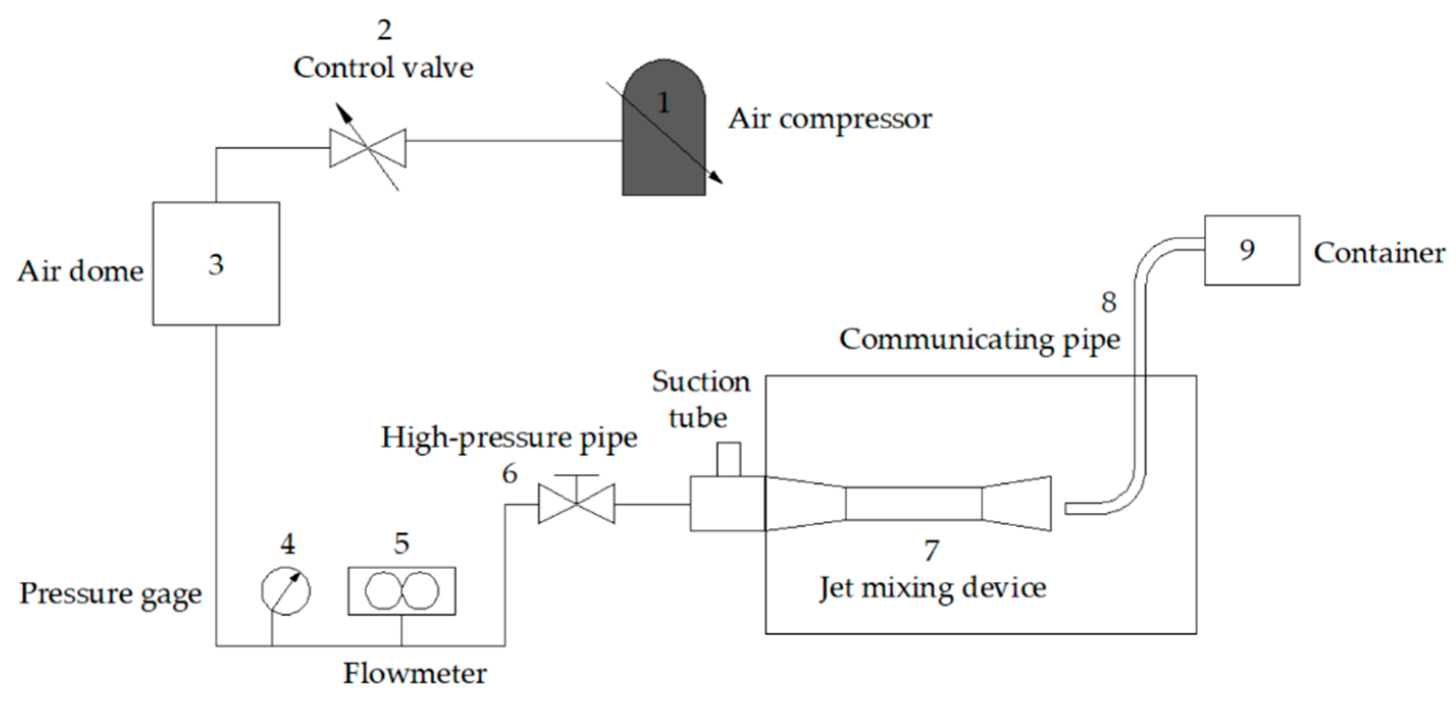
According to the model structure, four groups of jet mixing devices with an area ratio of 1.44 ( D h = 12   mm ,   L e = 12   mm ), 3.24 ( D h = 18   mm ,   L e = 18   mm ), 5.76 ( D h = 24   mm ,   L e = 24   mm ) and 9.00 ( D h = 30   mm ,   L e = 30   mm ) were made, respectively. The test system, as shown in Figure 3 was built, and compressed air with pressure P = 0.08 MPa was used as the working fluid. The injection fluid was n-dodecane, with a flow rate Q = 24 L/h. The spray droplets were dispersed by jet device 7 and introduced into container 9 through connecting pipe 8. The particle size of fog droplets in container 9 were tested by a Winner312 laser particle size analyzer, produced by Jinan Micro nano Company.

3.2.2. Diameter Size Test of Injected Bubbles

Based on the test system shown in Figure 3, the air compressor 1 was replaced by a screw pump, the mixing tank was filled with water, and a submerged jet was used. The water transported by the screw pump was spewed out at high speed through the nozzle of the jet mixing device 7, and air was injected to form bubbles. In order to keep the bubbles in a stable state, foaming agent was added in this process, and the gas-containing liquid was introduced into the laser particle size analyzer (SALD-7101) using the extraction tube to test the diameter size of bubbles.
The physical model parameters of the jet mixing device 7 are as follows: the nozzle diameter D z = 10   mm ; the throat diameter D h = 18   mm ; the area ratio A r = 3.24 ; the throat-nozzle distance L e = 10   mm ; the length of the throat tube L = 90   mm ; the feed volume was 2.03   m 3 / h ; and the nozzle outlet velocity was 7.20   m / s . The foaming agent was methyl isobutyl methanol with the dosage of 0.0124   mL / L . The suction volume is a variable parameter. By adjusting the opening degree of the inlet of the gas flowmeter, the injection volume was controlled to be 500   L / h , 400   L / h , 300   L / h , 200   L / h and 100   L / h , respectively.

4. Numerical Simulation Results and Discussion

4.1. Influence of Parameters on Reagent Suction Performance

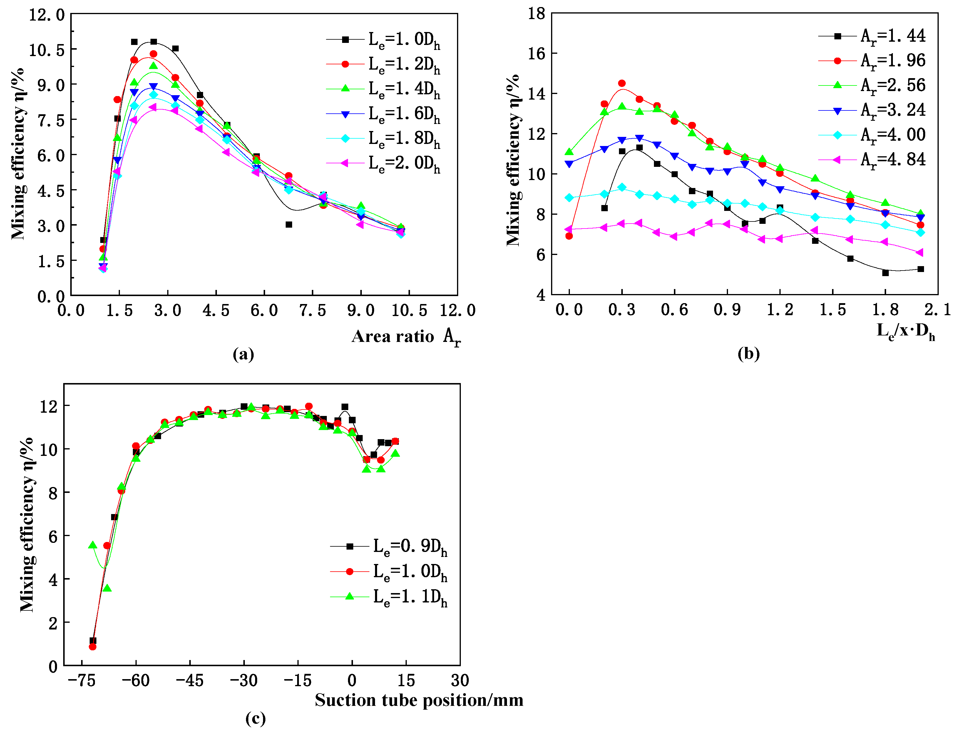
Many parameters affect the reagent suction performance of the jet mixing device. The method of finding the optimal value of each parameter step by step was adopted to optimize the optimal value range of area ratio A r , throat-nozzle distance L e , suction tube position, suction tube arrangement, throat tube length L and nozzle outlet velocity. The optimal value of the preorder parameters were also applied in the optimization scheme of the subsequent parameters. Table 1 shows the optimized variable parameter value scheme of area ratio A r and throat-nozzle distance L e . When the position of the suction tube is optimized, the area ratio A r = 2.56 and the throat-nozzle distance L e = 0.9 D h ~ 1.1 D h . When the arrangement of suction tube is optimized, the area ratio A r = 3.24 and the throat-nozzle distance L e = 0.3 D h ~ 0.6 D h . When the arrangement of suction tube is optimized, the area ratio A r = 3.24 and the throat-nozzle distance L e = 0.3 D h ~ 0.6 D h . When the throat length is optimized, the area ratio A r = 3.24 and the throat-nozzle distance L e = 0.6 D h .
As can be observed from Figure 4, when the area ratio A r is 1.96~3.24 and the throat-nozzle distance L e is 0.2 D h ~ 0.6 D h , the reagent suction performance of the jet mixing device is optimal. The position of the suction tube has little influence on the suction performance of the jet mixing device. Considering the reagent suction performance, the optimal position is 1/4~1/2 L z ( L z is the length of the nozzle) on the left side of the nozzle outlet.
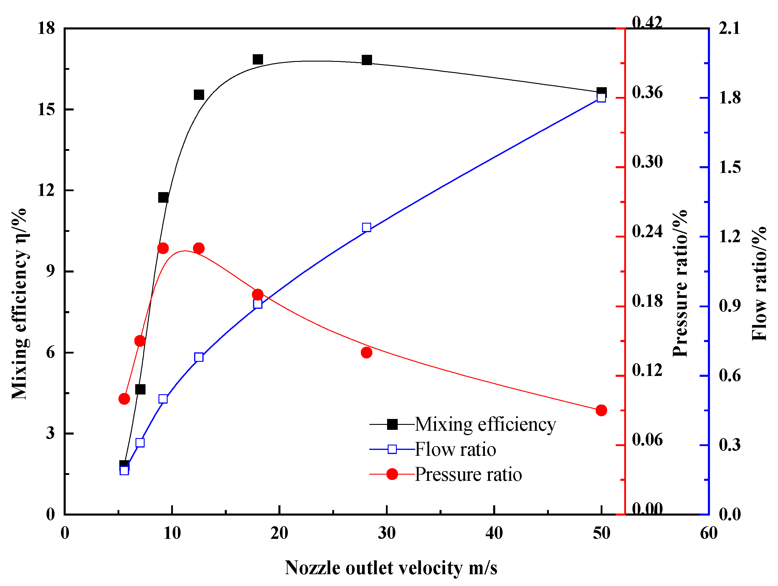
Figure 5 shows that the nozzle outlet velocity can effectively improve the injection capacity, but the increase in velocity will cause a loss of energy. Each group of jet mixing devices has the optimal pressure ratio and flow ratio coordination. With the increase in the speed, the reagent uptake gradually increased and the flow ratio also increased. The pressure ratio increased first and then decreased with the increase in velocity. The pressure ratio was the highest when the velocity was 9~13 m/s. When the speed was 18 m/s, the mixing efficiency was the best.

4.2. Influence of Parameters on Flow Field

4.2.1. Pressure Field Analysis

As shown in Figure 6, in the contraction section of the nozzle, because the pressure energy of the working fluid is converted into kinetic energy, the flow rate of the fluid reaches the maximum, the static pressure reaches the maximum gradient pressure drop, and the lowest pressure appears at the entrance of the suction tube. If the area ratio is smaller, the nozzle flow rate is larger and the static pressure is smaller. From the nozzle outlet to the throat tube inlet, the flow velocity of mixed fluid decreases and the static pressure increases gradually. In the throat tube, the working fluid and the ejector fluid mix fiercely at the beginning and then tend to be uniform, and the static pressure rises first and then becomes stable. If the area ratio is smaller, the static pressure rise in the throat tube is smaller. In the diffusion tube, the static pressure increases gradually along the axial direction, and tends to be gentle at the outlet. The static pressure at the outlet of the jet mixing device with different area ratios tends to be consistent, indicating that the length of the diffusion tube is reasonable. When the area ratio is the same, the throat-nozzle distance L e varies between 0.2 D h and 0.6 D h , and the axial distribution of static pressure tends to be consistent and overlapped, indicating that the throat-nozzle distance L e has little effect on the static pressure in the jet mixing device.
Figure 7 shows that with the increase in nozzle outlet velocity, the static pressure in the injection chamber increases rapidly. In the mixing chamber, a lower negative pressure area is formed around the nozzle. The larger the jet velocity is, the larger the area and value of the negative pressure area are. When the velocity is greater than 28.13m/s, the negative pressure area appears in the throat tube, and when the velocity increases to 50.00 m/s, the negative pressure area increases significantly. In general, in the throat tube, the working fluid and the ejector fluid mix from intense to uniform, and the static pressure gradually increases from negative pressure to stable.

4.2.2. Velocity Field Analysis

Figure 8 shows that the area ratio has a significant impact on the central velocity of the stream beam. The larger the area ratio is, the faster the attenuation of the central velocity is. The variation in throat-nozzle distance has little effect on the attenuation of the center velocity, but the small throat-nozzle distance ( L e = 0.2 D h ) makes the flow core exist at a long distance, which is evidently unfavorable to the diffusion and mixing of materials. According to the symmetrical velocity distribution of the injected fluid along the center line, the symmetrical arrangement of the suction tube has obvious effects.
Figure 9 shows that, when the suction tube is arranged on one side, the stream beam at the nozzle outlet has a certain deviation along the axis direction. The velocity distribution above the axis near the wall is more uniform than that below the axis near the wall, and the velocity of the whole section tends to be consistent at the throat tube outlet. When the suction tube is arranged symmetrically on both sides, the velocity image in the throat tube is displayed symmetrically along the axis, and the velocity of the section at the half position of the throat tube tends to be consistent. The suction tube is arranged symmetrically on both sides, which is more conducive to the mixing of materials.

4.2.3. Turbulence Intensity Distribution

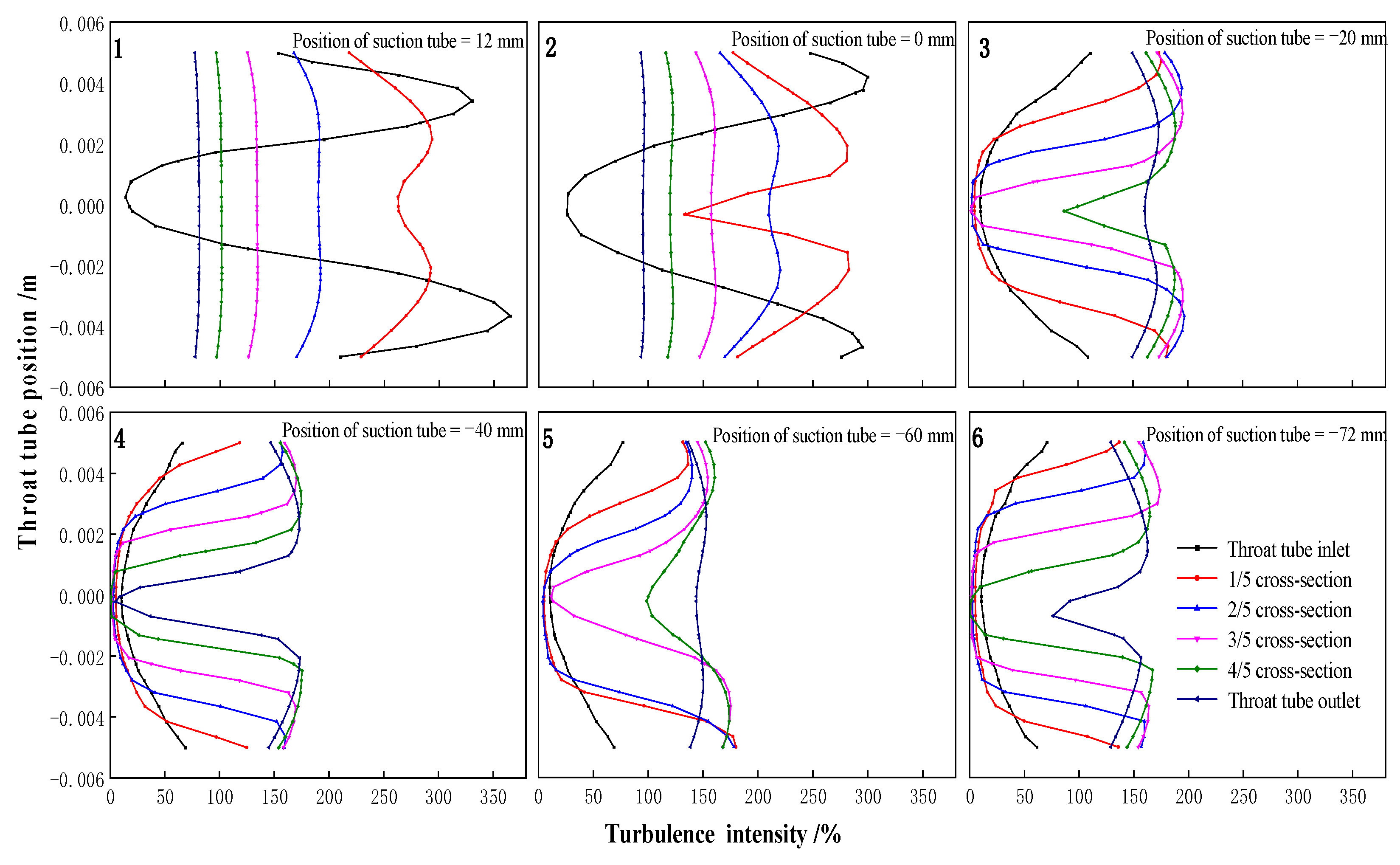
It can be observed from Figure 10 that, when the suction tube is directly facing the jet stream, the turbulence intensity of the throat tube inlet and 1/5 cross-section increases first and then decreases along the radial direction, while the turbulence intensity of all the points in the radial direction of the other cross-sections tends to be consistent; and the closer it is to the throat tube outlet, the more obvious it is, indicating that momentum exchange is completed in the throat tube. As shown in Figure 10(3–6), the turbulence of each cross-section presents a parabolic shape; the origin point of the parabola from the inlet to the 3/5 cross-section of the throat tube is at zero, indicating that the flow core of the stream beam reaches to the 3/5 cross-section of the throat tube. Therefore, from the perspective of turbulence intensity distribution, the arrangement of the suction tube should be in the positive convective core.
It can be observed from Figure 11 that the morphology of the turbulent region is independent of the length of the throat tube. When the throat tube length L is less than 60 mm, there is still a high turbulence intensity in the diffusion tube. When the throat tube length L is greater than 90 mm, the turbulence region is mainly concentrated in the throat tube; as the throat tube length L increases, the turbulence region does not increase and is mainly concentrated in the 0–120 mm region. It indicates that the momentum exchange between the working fluid and the injection fluid is completed in this region.

5. Experimental Results and Discussion

It can be observed from Figure 12 that the dispersion ability of the four groups of the jet mixing devices with different area ratios is relatively consistent, but the dispersion effect is the best when the area ratio A r = 3.24 . When the area ratio a = 3.24, the average droplet diameter decreases, and the accumulative production rate of particle sizes smaller than 7.3 μm, 8.9 μm, 13.1 μm and 20.1 μm are 50%, 70%, 80% and 90%, respectively. All the droplet diameters are smaller than 38 μm. The correctness of the numerical simulation results is verified by the fog droplet size test. When the area ratio A r = 3.24 , the flow field distribution characteristics are the most ideal, providing the best conditions for the dispersion of the injection fluid in the working fluid.
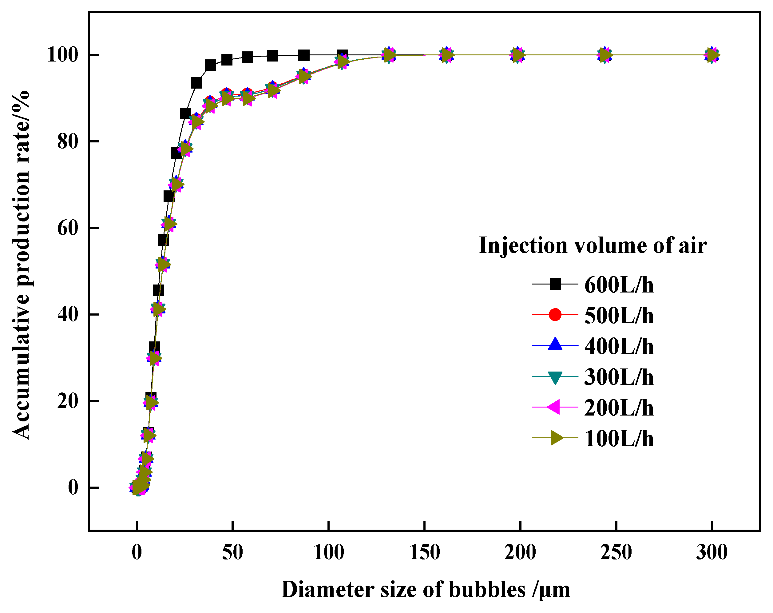
It can be observed from Figure 13 that, under the optimized parameters of the jet mixing device, all the injected air is pulverized and dispersed evenly. The bubble diameter size is mainly concentrated in 5 ~ 40   μ m , and the accumulative production rate is 80%; the dominant diameter size of the bubbles is 9 ~ 15   μ m ,and the accumulative production rate is 30%. More than 90% of the bubbles are less than 45   μ m .
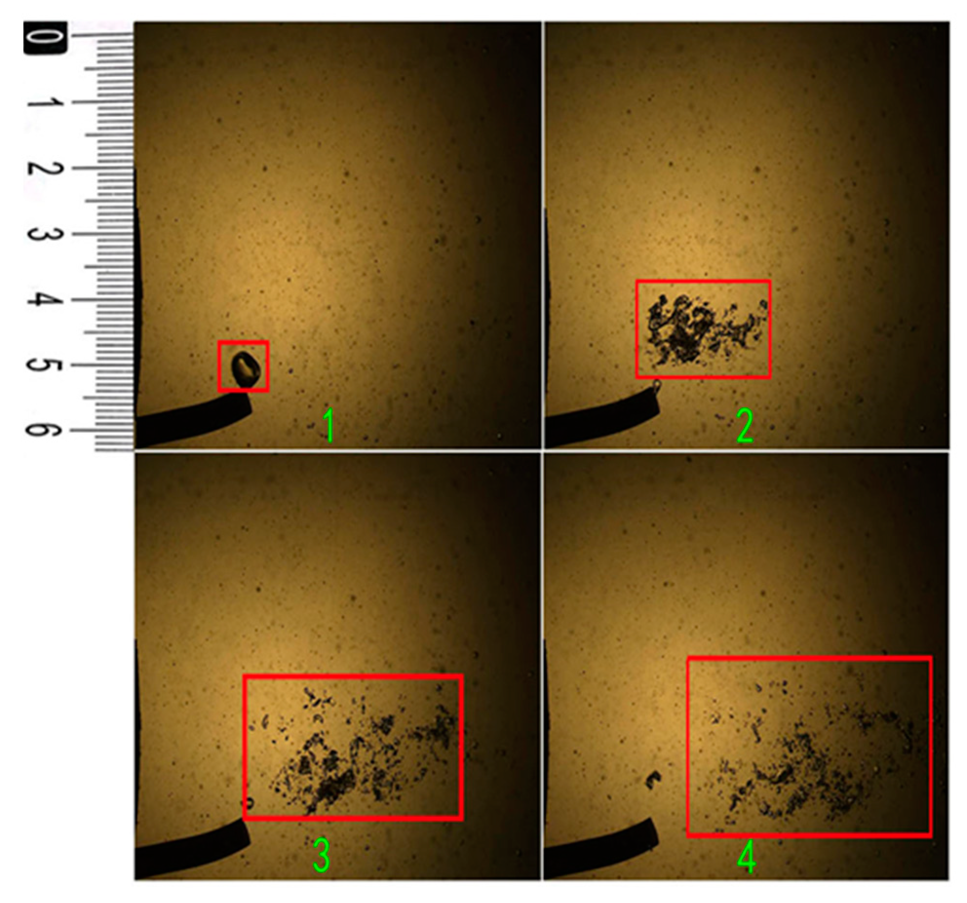
Figure 14 is the dynamic capture diagram of bubble jet coiling and crushing. When the nozzle outlet velocity is 7.20 m/s, a high-speed camera is used to capture the coiling and crushing image of the monomer bubbles by the jet stream. As shown in the figure, the bubble will be instantly crushed into a large number of small diameter bubbles. It shows that the jet mixing device with optimized parameters can meet the performance requirements of the coal slime floating-mixing device.

6. Conclusions

(1)
In this paper, a jet stirring combined device of coal slime floatation and mixing (China Patent, ZL2015108627218) is proposed. The main function of the jet mixing device is to realize the full mixing of reagent, air bubbles and coal slurry. The main function of the stirring apparatus is to keep the multiphase particles suspended in the mixing tank. The test of the jet mixing effect and diameter size migration law of injected bubbles show that the design idea of this device is correct.
(2)
Considering the suction performance, when the area ratio A r = 1.96 ~ 3.24 , the throat-nozzle distance L e = 0.2 D h ~ 0.6 D h , the suction tube is located at 1/4 L z ~1/2 L z position on the left side of the nozzle outlet and is symmetrically arranged, and the length of the throat tube is 6 D z ~12 D z , the suction performance of the jet mixing device is the best. The nozzle outlet velocity can effectively improve the injection capacity, but the increase in velocity will cause a loss of energy. Each jet mixing device has the optimal pressure ratio and flow ratio coordination, and the mixing efficiency is the highest when the velocity is 18m/s.
(3)
According to the flow field distribution characteristics in the device, the area ratio has a more significant effect. If the area ratio is larger, the turbulence intensity around the flow core is larger, the pressure drop in the throat tube is faster, the flow core also disappears faster; and the mixing between the working fluid and the injection fluid is more favorable. The throat-nozzle distance has little effect on the flow field distribution. When the throat-nozzle distance is less than 0.2 D h , the flow core is longer, which is unfavorable to fluid mixing. The optimal throat-nozzle distance is 0.3 D h ~0.6 D h . The outlet area of the nozzle (0~ L e ) directly opposite the suction tube is the most ideal, which is conducive to kinetic energy exchange between the working fluid and the ejector fluid in the throat tube. The suction tube is arranged symmetrically on both sides, and its turbulence intensity image is highly symmetrical, which is conducive to momentum exchange and mass mixing between the working fluid and the injection fluid in the throat tube. When the throat tube length L is greater than 9 D z , the turbulent region does not increase. Considering the mixing characteristics of the flow field, the throat tube length should be greater than 9 D z . Under different nozzle exit velocities, the velocity of each point in the cross section below the middle part of the throat tube (greater than 10 D z ) tends to be consistent, indicating that the mixing of working fluid and injection fluid can be completed in a limited length of the throat tube, independent of the nozzle outlet velocity.
(4)
According to the fog droplet size test, the dispersion effect is the best when the area ratio A r = 3.24 , that is, when the area ratio A r = 3.24 , the flow field distribution characteristics are the most ideal, providing the best conditions for the dispersion of the injection fluid in the working fluid. According to the diameter size test of injected bubbles, under the optimized parameters of the jet mixing device, the single bubbles will be instantly crushed into small diameter size and a large number of bubbles. More than 90% of bubbles were smaller than 45μm under the synergistic action of foaming agent.

Author Contributions

Conceptualization, W.Z. and J.Z.; Data curation, J.X.; Investigation, S.W. and C.C.; Methodology, W.Z. and C.C.; Project administration, J.Z.; Resources, C.C.; Software, J.X.; Writing—original draft, W.Z. and S.W.; Writing—review and editing, W.Z. and S.W. All authors have read and agreed to the published version of the manuscript.

Funding

This research is supported by the University Scientific Research Project of The Education Department of Anhui Province (KJ2021A0429), the University Excellent Talents Training Funding Project of the Education Department of Anhui Province (gxyqZD2021109), the Natural Sciences Foundation of Anhui Province (2108085ME160) and the Open Foundation of State Key Laboratory of Mining Response and Disaster Prevention and Control in Deep Coal Mines (SKLMRDPC19KF11).

Institutional Review Board Statement

Not applicable.

Informed Consent Statement

Not applicable.

Data Availability Statement

The data that support the findings of this study are available from the corresponding author, upon reasonable request.

Acknowledgments

Special thanks to Zhu Jinbo of Anhui University of Science and Technology for his guidance on this study, and also to all those who participated in this study.

Conflicts of Interest

The authors declare no conflict of interest. The funders had no role in the design of the study; in the collection, analyses, or interpretation of data; in the writing of the manuscript, or in the decision to publish the results.

References

  1. Güney, A.; Nal, G.; Ergut, M. Beneficiation of fine coal by using the free jet flotation system. Fuel Process. Technol. 2002, 75, 141–150. [Google Scholar] [CrossRef]
  2. Deng, X.W.; Liu, J.T.; Wang, Y.T.; Cao, Y.J. Velocity distribution of the flow field in the cyclonic zone of cyclone-static micro-bubble flotation column. Int. J. Min. Sci. Technol. 2013, 23, 89–94. [Google Scholar] [CrossRef]
  3. Gong, M.; Li, C.; Li, Z. Numerical analysis of flow in a highly efficient flotation column. Asia-Pac. J. Chem. Eng. 2015, 10, 84–95. [Google Scholar] [CrossRef]
  4. Wang, A.; Yan, X.; Wang, L.; Cao, Y.; Liu, J. Effect of cone angles on single-phase flow of a laboratory cyclonic-static micro-bubble flotation column: PIV measurement and CFD simulations. Sep. Purif. Technol. 2015, 149, 308–314. [Google Scholar] [CrossRef]
  5. Shen, X.; Chen, Q.; Li, S. Velocity and pressure distributions characteristics of coal slurry in floatation cyclone. Procedia Earth Planet. Sci. 2009, 1, 814–818. [Google Scholar]
  6. Chen, W.-Y.; Wang, J.-B.; Jiang, N.; Zhao, B.; Wang, Z.-D. Numerical simulation of gas-liquid two-phase jet flow in air-bubble generator. J. Cent. South Univ. Technol. 2008, 15, 140–144. [Google Scholar] [CrossRef]
  7. Hacifazlioglu, H. Enrichment of Silica Sand Ore by Cyclojet Flotation Cell. Sep. Sci. Technol. 2014, 49, 1623–1632. [Google Scholar] [CrossRef]
  8. Salem-Said, A.H.; Fayed, H.; Ragab, S. Numerical Simulations of Two-Phase Flow in a Dorr-Oliver Flotation Cell Model. Minerals 2013, 3, 284–303. [Google Scholar] [CrossRef] [Green Version]
  9. Tasdemir, T.; Tasdemir, A.; Oteyaka, B. Gas entrainment rate and flow characterization in downcomer of a Jameson cell. Physicochem. Probl. Miner. Process. 2011, 47, 61–78. [Google Scholar]
  10. Ma, J.; Qiu, B.J.; Yan, R.; Zhu, B.F. Study on the Working State of Jet-Mixing Apparatus. Appl. Mech. Mater. 2014, 563, 219–223. [Google Scholar] [CrossRef]
  11. Dörpmund, M.; Cai, X.; Walgenbach, M.; Vondricka, J.; Schulze Lammers, P. The Challenge of Cleaning Direct-Injection Systems for Pesticide Application. Trans. ASABE 2012, 55, 1643–1650. [Google Scholar] [CrossRef]
  12. Ni, C.; Jin, M.; Chen, Y.; Xie, G.; Peng, Y.; Xia, W. Improving the Recovery of Coarse-Coal Particles by Adding Premineralization Prior to Column Flotation. Int. J. Coal Prep. Util. 2016, 37, 87–99. [Google Scholar] [CrossRef]
  13. Lin, L.I.; Liu, J.; Wang, L.; Hesheng, Y.U. Numerical simulation of a self-absorbing microbubble generator for a cyclonic-static microbubble flotation column. Int. J. Min. Sci. Technol. 2010, 20, 88–92. [Google Scholar]
  14. Wang, L.; Jia, Y.; Yan, X.; Zhou, C. Gas–liquid numerical simulation on micro-bubble generator and optimization on the nozzle-to-throat spacing. Asia-Pac. J. Chem. Eng. 2016, 10, 893–903. [Google Scholar] [CrossRef]
  15. Yang, R.Q.; Wang, H.F.; Liu, J.C. Jet Flotation Column System Structure Design and Numerical Simulation of Two-Phase Flow. Adv. Mater. Res. 2013, 616–618, 655–661. [Google Scholar] [CrossRef]
  16. Taşdemir, A.; Taşdemir, T.; Öteyaka, B. The effect of particle size and some operating parameters in the separation tank and the downcomer on the Jameson cell recovery. Miner. Eng. 2007, 20, 1331–1336. [Google Scholar] [CrossRef]
  17. Vondřička, J. Study on the Process of Direct Nozzle Injection for Real-Time Site-Specific Pesticide Application; Rheinische Friedrich-Wilhelms-University: Bonn, Germany, 2008. [Google Scholar]
  18. Xu, X.C.; Qiu, B.J.; Deng, B.; Jia, F.W. Analysis on Online Mixing Performance of Jet-Mixing Apparatus. Adv. Mater. Res. 2011, 347–353, 417–421. [Google Scholar] [CrossRef]
  19. Jing, M.; Qiu, B.; Yan, R. Simulated Analysis of the Mixing Performance of Jet-mixing Apparatus. In Proceedings of the 2015 International Conference on Intelligent Systems Research and Mechatronics Engineering, Zhengzhou, China, 11–14 April 2015. [Google Scholar]
  20. Xu, Y.; Wang, X.; Zheng, J.; Zhou, F. Simulation and experiment on agricultural chemical mixing process for direct injection system based on CFD. Trans. Chin. Soc. Agric. Eng. 2010, 26, 148–152. [Google Scholar]
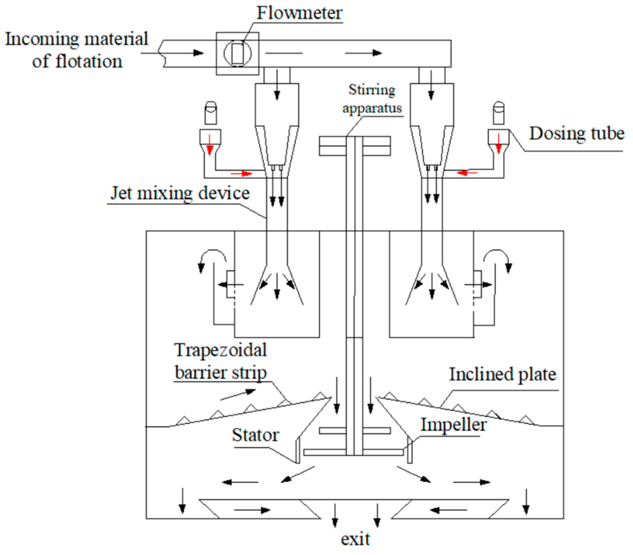
Figure 1. Structure diagram of jet-stirring combined device of coal slime floatation and mixing.
Processes 10 00933 g001
Figure 2. Structure and working diagram of the jet mixing device.
Processes 10 00933 g002
Figure 3. Fog droplet size test system.
Processes 10 00933 g003
Figure 4. Influence of structural parameters on reagent suction performance. (a) Effects of area ratio on mixing efficiency under different throat-nozzle distance. (b) Effect of throat-nozzle distance on mixing efficiency under different area ratio. (c) Effect of suction tube position on mixing efficiency under different throat-nozzle distance.
Processes 10 00933 g004
Figure 5. Influence of nozzle outlet velocity on mixing efficiency.
Processes 10 00933 g005
Figure 6. Influence of area ratio and throat-nozzle distance on static pressure.
Processes 10 00933 g006
Figure 7. Influence of nozzle outlet velocity on static pressure.
Processes 10 00933 g007
Figure 8. Effect of area ratio and throat-nozzle distance on axial velocity.
Processes 10 00933 g008
Figure 9. Influence of suction tube arrangement on axial velocity.
Processes 10 00933 g009
Figure 10. Effect of suction tube position on turbulence intensity.
Processes 10 00933 g010
Figure 11. Effect of throat tube length on axial turbulence intensity.
Processes 10 00933 g011
Figure 12. Fog droplet size test results.
Processes 10 00933 g012
Figure 13. Bubble size distribution diagram.
Processes 10 00933 g013
Figure 14. Dynamic capture diagram of bubble jet coiling and crushing.
Processes 10 00933 g014
Table 1. Variable parameter value scheme.
SchemeNozzle
Diameter Dz/mm
Throat Tube
Diameter Dh/mm
Throat-Nozzle
Distance Le/mm
Position of Suction Tube Inlet
Area ratio optimization D z = 10 mm D h = 10 + 2 n (n = 0, 1 … 10, 11) L e = 1.0 D h + 0.2 N D h
(N = 0, 1 … 4, 5)
middle
Throat-nozzle distance optimization D z = 10 mm D h = 10 + 2 n (n = 1, 2 … 5, 6) L e = 1.0 D h ± 0.1 N D h
(N = 1, 2 … 9, 10)
middle
Publisher’s Note: MDPI stays neutral with regard to jurisdictional claims in published maps and institutional affiliations.