Article

Self-Circulating Evaporative Cooling System of a Rotor and Its Experimental Verification

1
Institute of Electrical Engineering (IEE), Chinese Academy of Sciences (CAS), Beijing 100190, China
2
School of Electronic, Electrical and Communication Engineering, University of Chinese Academy of Sciences, Beijing 100049, China
*
Author to whom correspondence should be addressed.
Processes 2022, 10(5), 934; https://doi.org/10.3390/pr10050934
Submission received: 1 April 2022 / Revised: 27 April 2022 / Accepted: 2 May 2022 / Published: 9 May 2022
(This article belongs to the Special Issue Design, Concepts and Applications of Electric Machines)

Abstract

:
With the development of hydropower, the heat problem of a rotor cannot be ignored. This paper presents a topology of an evaporative cooling system for rotors. The system seals the pole coil in a tank and immerses the coil in the insulating coolant with a suitable boiling point. The latent heat of vaporization during the boiling of coolant is used to control the temperature rise of the pole coil. After explaining the circulation principle of the system, the effectiveness of the cooling system is verified by experiments. A small-scale experimental platform has been set up to test the effectiveness of the new topology. The comparison experiment with air-cooling shows that the phase change cooling system can not only provide hundreds of times the heat transfer capacity of air-cooling, but also the temperature rise of the coil is half that of air cooling. Based on the experimental results, the calculated formula of the heat transfer coefficient of the evaporative cooling system in the rotating state was fitted, and the deviation of the calculated result could be kept at less than 25%. Thanks to the evaporative cooling system, the rotor carries a high current density.

1. Introduction

Hydropower is among the cleanest sources of electricity. The International Energy Agency (IEA) emphasizes in its 2021 Net Zero by 2050 report that global hydropower capacity needs to at least double by 2050. However, the hydropower resources with relatively low utilization difficulty have been almost fully developed. At present, the major large-scale hydro-generators to be built are concentrated in pumped storage and conventional generators with high head and large capacity. These high speed, slender machines will inevitably encounter more ventilation and heat dissipation problems in the rotors. Not only are the large capacity machines faced with thermal problems, but some small capacity hydro-generators are also faced with ventilation and heat dissipation problems due to structural limitations [1]. In order to solve these rotor problems, many practitioners have done a lot of research.
Due to structural and cost constraints, it is difficult for hydro generators to use hydrogen cooling [2]. Water and air are the main cooling media of hydro generators. Water cooling technology can be successfully applied to vertical salient pole generators, but it still faces a high cost and the safety risk of water leakage [2,3]. For the hydro generators cooled with air, 20–40% of the total losses are air friction and ventilation losses [4]. So, air-cooling technology has been studied extensively.
Because of the complexity of flow field inside the generator, it is difficult to obtain sufficient details through analytical calculation. Nowadays, computational fluid dynamics (CFD) is an important means to study the ventilation and cooling of generators [5]. Li Weili’s team has done a lot of work in the calculation of the rotor ventilation of hydro-generators. This work includes the calculation of heat transfer coefficient at different positions of poles [6,7,8,9], the temperature rise characteristics when the rotor ducts are blocked [10], and local improvement of ventilation structure [11,12]. Cravero et al. found that the rotor instability due to operating near the surge can cause larger temperature variations [13].
There are also improvements in other aspects of air-cooling technology. Jamshidi et al. studied the flow of cooling air in a generator model by PIV (Particle Image Velocimetry) measurements and other means, and then used experimental data to validate the flow field simulations [14]. Majer et al. analyzed windage loss generated with different rotor construction elements [15]. Traxler et al. presented an advanced calculation algorithm of temperature rise in large salient-pole synchronous machines for hydro power plants [4].
Compared with conventional means, evaporative cooling technology is a new way, and has been an alternative for the water-cooling method in the three gorges’ hydro-generator [16,17,18]. There are many studies on insulation systems, working medium selection [19], resistance calculation [20,21,22], temperature rise calculation [23,24,25], stress calculation [26] and so on [27,28]. These studies prove that the larger the unit is and the more difficult it is to cool, the more advantages the evaporative cooling technology has [29,30]. Up to now, most of the evaporative cooling technology of hydro generators concentrates on stators. The study of a solid, liquid and gas three-phase insulation system in an immersion environment shows that an immersion evaporative cooling system can achieve a good balance among heat transfer, insulation, and weight reduction [31,32]. The research content of rotor evaporative cooling technology is less, and the existing research focuses on the rotor with a non-salient pole of a horizontal generator [33].
In order to meet the rotor cooling requirements of high-water head and large capacity vertical generators in the future, a new rotor evaporative cooling system is proposed in this paper. A small-scale test bed was set up to test the effectiveness of this technique. Based on this, we hope to learn what advantages the new cooling technology has over air-cooling, and also hope to alleviate the anxiety about structural complexity to some extent.

2. Thermal Hydraulics Model of Self-Circulating Evaporative Cooling System of Rotor

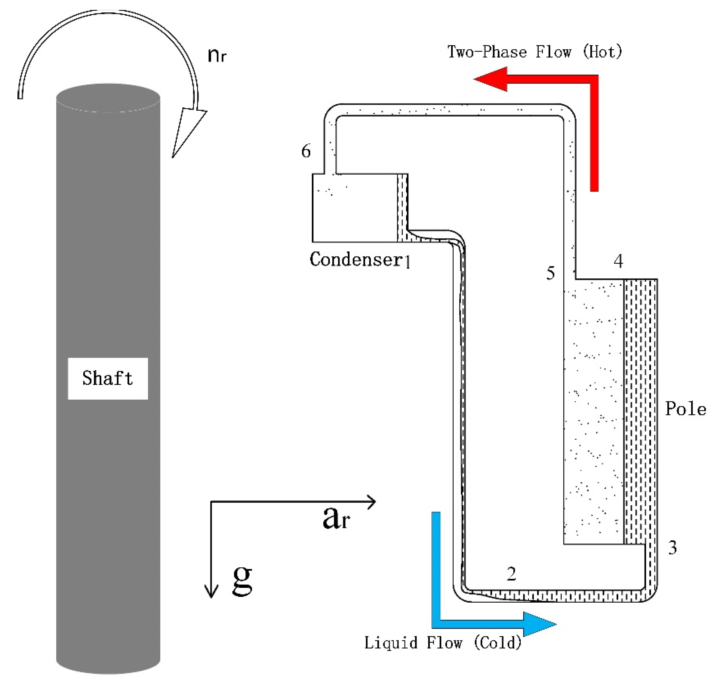
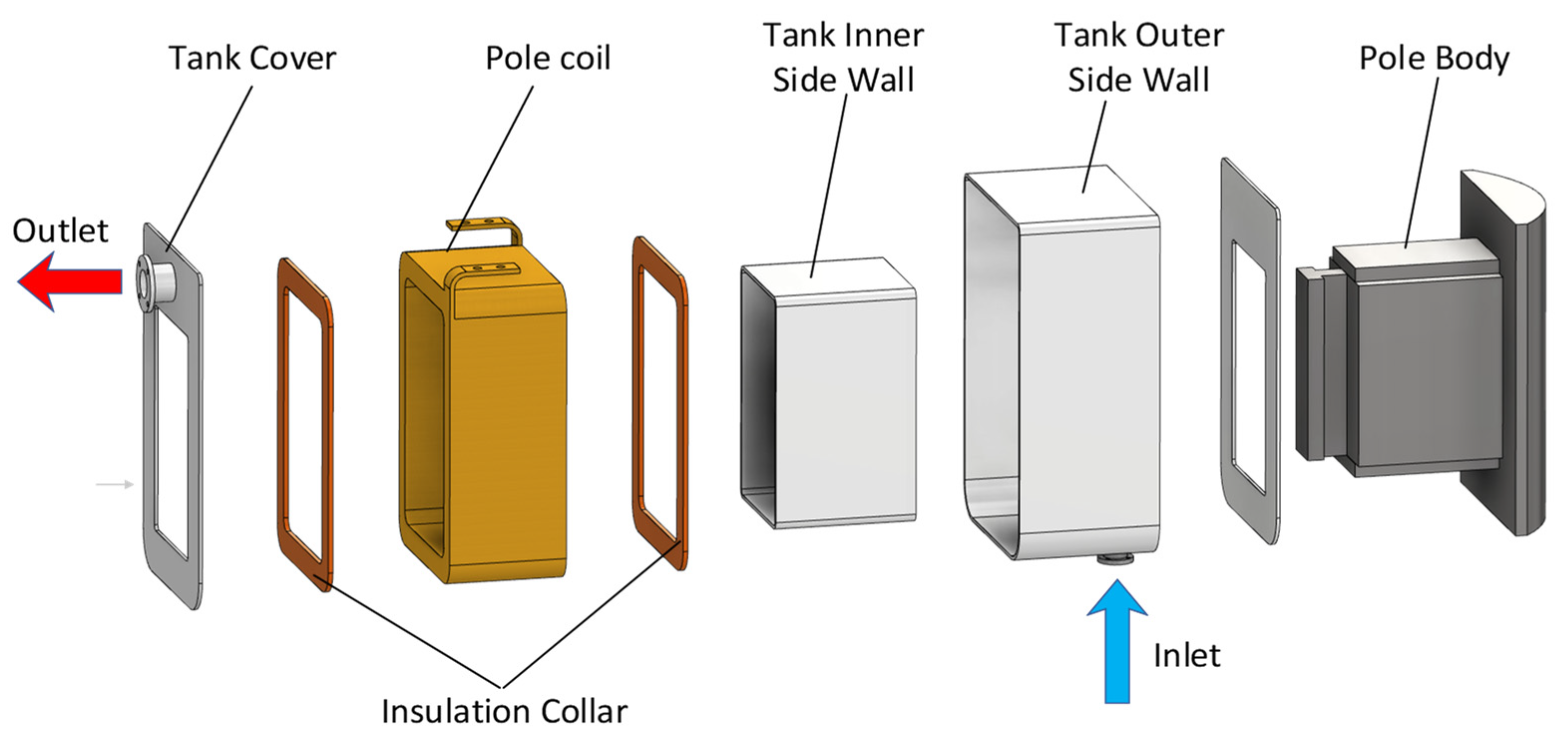
2.1. The Structural Topology

The rotor evaporative cooling system described in this paper is composed of condensers and poles with sealed tanks. Figure 1 shows the structure of the pole with evaporative cooling. The tank is filled with an insulating cooling medium with an appropriate boiling point. Once the generator starts working, the pole coils will heat up. The cooling medium absorbs heat from the coil and the temperature rises. When the temperature of the coolant reaches boiling point, it boils. Under centrifugal acceleration, the vaporized working medium leaves the pole through the outlet and enters the condenser mounted on the rotor spider or yoke. In the condenser, the coolant is condensed into liquid and then flows back to the pole through the inlet to participate in the next cycle. Pipes are used to connect the pole and the condenser. As we all know, when the pressure is constant, the boiling point of the liquid remains constant. The latent heat of phase transition is much greater than the specific heat. This means that the temperature of the cooling medium will not rise significantly, but will absorb a lot of heat. As a result, the temperature rise of the pole winding is controlled at a low level.
Figure 2 is a schematic diagram of the rotor evaporative cooling system. In order to be able to analyze the cooling system explicitly, the essential components of the rotor, such as rotor spider, are not shown. Under the centrifugal acceleration of the rotor, a considerable component of fluid buoyancy is directed towards the shaft. The two pipes connecting the condenser and the pole circulate single-phase and two-phase fluids respectively, and the average density of the fluids in the two pipes is obviously different. Like a self-circulating evaporative cooling system in a gravitational field, the difference of the fluid densities in the two pipes leads to different pressure drops, which is the fundamental driving force of the system circulation:
1-condenser outlet; 2-liquid level; 3-pole inlet; 4-evaporation point (the coolant begins to boil at this point); 5-pole outlet; 6-condenser inlet.

2.2. The Governing Equations

Taking the coolant of a certain mass as the object, the energy equation in each stage of the circulation is in the form of Equation (1):
q = u + ( p β v β p α v α ) + 1 2 ( c f β 2 c f α 2 ) + g ( l β l α ) + r α r β a c ( r ) d r + w i
a c ( r ) = ( π n r 30 ) 2 r .
In the formula, q is the heat flux on the wall, u is the internal energy, p is the pressure, v is the specific volume, c f is the velocity, g is acceleration of gravity, l is the axial position, r is the radial position, a c ( r ) is the centrifugal acceleration, n r is the revolving speed in rev/min, and w i is the work. Corner markers α and β represent the beginning and end of one stage respectively. ( p β v β p α v α ) is the change in flow work. 1 2 ( c f β 2 c f α 2 ) is the change in kinetic energy. g ( l β l α ) is the change in gravitational potential energy. r α r β a c ( r ) d r is the change in centrifugal potential energy. Since the circulation system does no work, w i = 0 .
In the pole, the coolant absorbs the excitation losses of rotor, q 35 > 0 . Part of this absorbed heat increases the enthalpy of the workin0g medium, and part is converted to kinetic and potential energy by steam expansion. In the condenser, the vapor is cooled into liquid, q 61 < 0 . The energy equation for each section is as follows:
Between   point   1   and   3 :   0 = u 13 + ( p 3 v 3 p 1 v 1 ) + 1 2 ( c f 3 2 c f 1 2 ) + g ( l 3 l 1 ) + r 1 r 3 a c ( r ) d r
Between   point   3   and   5 :   q 35 = u 35 + ( p 5 v 5 p 3 v 3 ) + 1 2 ( c f 5 2 c f 3 2 ) + g ( l 5 l 3 ) + r 3 r 5 a c ( r ) d r
Between   point   5   and   6 :   0 = u 56 + ( p 6 v 6 p 5 v 5 ) + 1 2 ( c f 6 2 c f 5 2 ) + g ( l 6 l 5 ) + r 5 r 6 a c ( r ) d r
Between   point   6   and   1 :   q 61 = u 61 + ( p 1 v 1 p 6 v 6 ) + 1 2 ( c f 1 2 c f 6 2 ) + g ( l 1 l 6 ) + r 6 r 1 a c ( r ) d r .
According to Equations (3)–(6), the potential energy of the fluid increases when it flows from the pole to the condenser. In the pipe where the fluid flows from the condenser to the pole, its potential energy decreases. The heat absorbed by the coolant in the pole changes the thermodynamic state of coolant and enables it to obtain the ability to do work, to overcome friction resistance and form a complete thermal cycle.

2.3. Evaluation of the Cooling System

The evaluation of a cooling system can be carried out from two aspects: heat dissipation efficiency and technology. In this paper, the former takes the heat transfer coefficient as the index, while the latter takes system gauge pressure as the index.
When we consider whether a cooling technique is effective, we can use the following expression:
q = h T ,
where h is the heat transfer coefficient and T is the temperature difference between the hot wall surface and the coolant. A larger heat transfer coefficient corresponds to a more efficient heat transfer process.
A major weakness of the rotor liquid cooling system is the static pressure caused by a centrifugal force. Based on this consideration, the pressure distribution of a rotor phase change cooling system must be concerned.

3. Materials and Methods

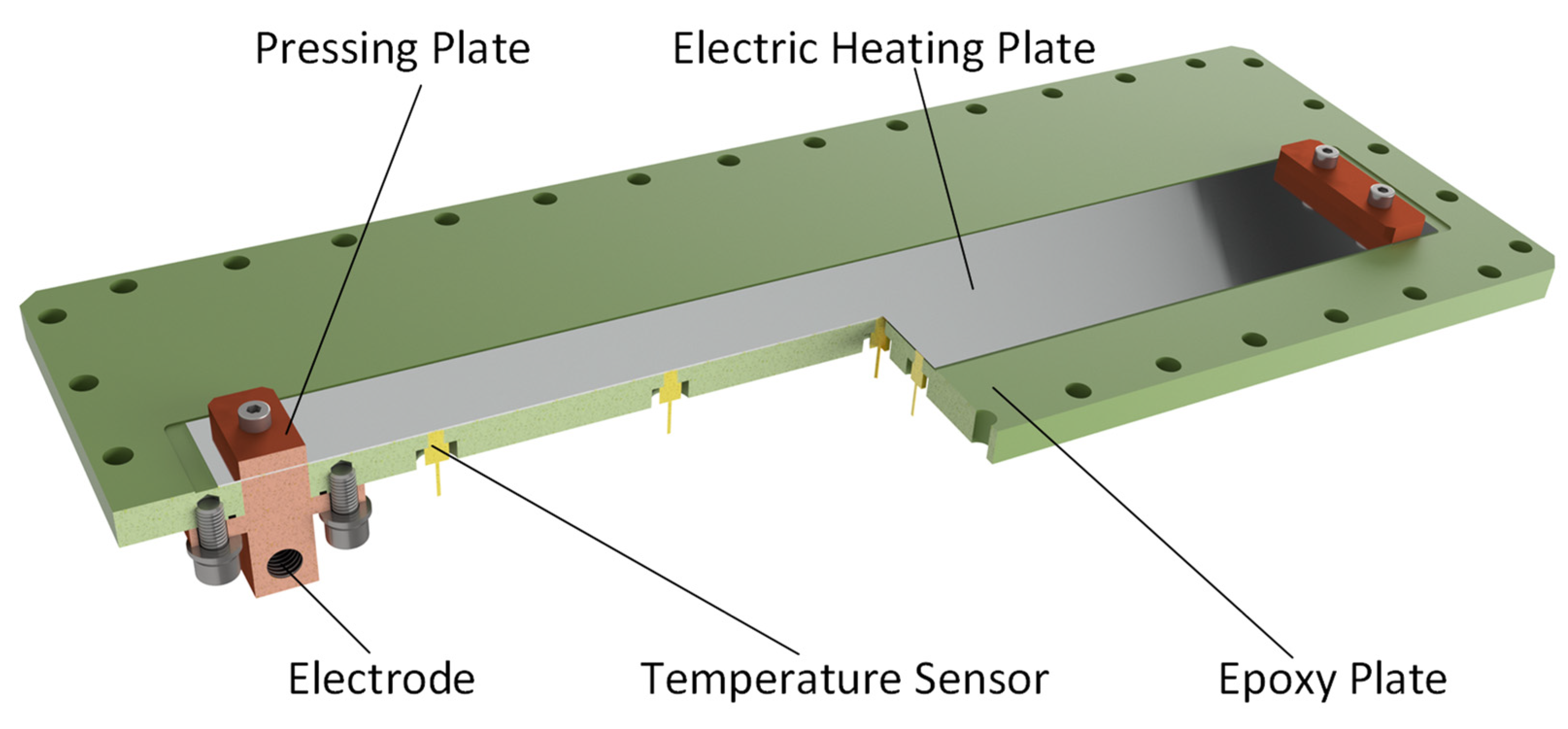
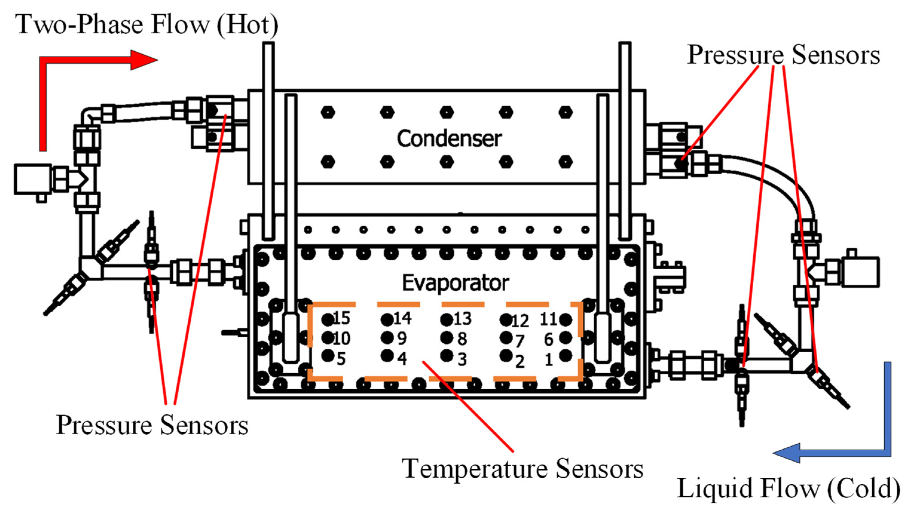
3.1. Experimental Platform Design

To verify the effectiveness of the rotor self-circulating evaporative cooling system proposed in this paper, an experiment was designed. The experimental device is shown in Figure 3. The experimental carrier was a rotor driven by a motor through belts. The rotor was divided into three sections, the middle of which was the experimental section. A slip ring for communication and a slip ring for power supply to the electric heating plate were installed above and below the experimental section, respectively. The total height of the experimental device was nearly 2.2 m. The radius of the rotation of the evaporator was about 0.4 m.
The composition of the experimental section was consistent with the topology expressed in Figure 2, except that the condenser and the evaporator used to simulate the pole had the same height and the same axial position. The evaporator was a box made up of an aluminum alloy frame and two insulating covers. As shown in Figure 4, in one of the two insulating covers, an electric heating plate was installed on the inner side as the heating wall. The electric heating plate was made of Cr20Ni80 with a thickness of 0.5 mm. Fifteen temperature sensors, which were made of Pt100, were evenly distributed on the outer side of the electric heater to measure the wall temperature. The location of temperature measurement points is shown in Figure 5. Since the metal plate was thin enough and had high thermal conductivity (15 W/mK), the temperature sensor could be considered to measure the temperature of the heat exchange wall.
Pressure monitoring is essential for the phase change cooling system. At the evaporator, the other insulating cover was fitted with pressure sensors. The positions of the pressure sensors corresponded to the temperature measurement points on the heating plate. Four pressure sensors were arranged at the inlet and outlet of the evaporator and condenser. In addition, the elbow near the inlet of the evaporator was at the lowest position of potential energy, where the static pressure was the largest. Pressure sensors were placed on the outside corner of the elbow to monitor the maximum pressure of the system.
The measuring equipment and related parameters used in the experiment are listed in Table 1.

3.2. The Experimental Process

The experiment was divided into two stages. During the air-cooling stage, the cover of the evaporator for mounting the pressure sensors was removed. When the rotor rotated, electric current was applied to the heating plate and air was blown over its surface. During the phase change cooling stage, the removed cover was added. The evaporator was filled with an evaporative cooling medium. When the experiment continued, the coolant provided heat dissipation for the heating plate.
In the air-cooling stage, the temperature between the wind and the heating plate was recorded, and the difference between the two was T in Formula (7). In the phase change cooling stage, the pressure value corresponding to the temperature measurement point was recorded. The boiling point at local pressure can be queried according to the table of physical properties of the working medium. The temperature difference between the boiling point and the heating plate was T in Formula (7). Finally, the heat transfer coefficient under different working conditions can be calculated according to the heating flux and temperature difference.
In this experiment, the maximum temperature of the heat plate was limited to 100 °C. If a higher temperature occurred, the sealing material on the back of the heating plate would denature, leading to coolant leakage during the phase change cooling stage. In the air-cooling stage, the temperature of the air is 18 °C and the humidity is about 30%. In the phase change cooling stage, R113 was chosen as the evaporative cooling medium. It boils at about 47 °C at one atmosphere. There was 18 °C cooling water in the condenser, and the water flow rate was high enough that the temperature difference between the inlet and outlet was quite small.
The three control variables during the experiment are listed in the Table 2. It can be predicted that the heat transfer coefficient of air cooling is in the order of magnitude of tens. The local temperature rise in convective heat transfer is proportional to the heat flux. Therefore, the heat flux in air-cooling stage starts from a very small amount and gradually increases to obtain the maximum value satisfying the condition of temperature rise. The phase change stage, however, requires only the maximum heat flux possible for future large machines. According to calculations, the value is between 10,000 and 40,000 W/m2. The speed setting was divided into four grades downward according to the maximum speed that the current experimental platform can achieve.

4. Results and Discussion

4.1. The Results of Air-Cooled Stage

Because the resistance of the heating plate is too small to adjust the voltage any lower, the heat flux cannot be lower than 600 W/m2. In that case, the voltage is only 0.368 V, the temperatures of 15 points are all around 80 °C. Therefore, there are only two groups of experimental data in the air-cooling stage, which are the average temperature of 80 °C and 100 °C, respectively. The air-cooling convective heat transfer coefficient of the model calculated according to the experimental results is presented in Figure 6. Since the air temperature is about 20 °C, the temperature rise of 80 °C in the figure corresponds to the limit case of the wall temperature of 100 °C. The convective heat transfer coefficient increases with the increase of rotational speed and heat flux. However, the maximum value under experimental conditions is only 32.8.
According to Figure 6, the air-cooled convection heat transfer coefficient increases significantly with the increase of rotational speed. With three times the linear velocity, the heat transfer coefficient increases more. However, the heat transfer coefficient obtained from the air-cooling experiment may be larger than that of a real machine of the same diameter and speed. This is because real rotors cannot create favorable convection conditions that are completely upwind.
Although the heat flux of the heating plate is uniform, the temperature differences are larger under higher heat flux. This shows that, even with such simplified structures, the heat transfer coefficients on the heat source surface cannot be guaranteed to be the same everywhere. For real machines, the temperature inhomogeneity will be more pronounced.

4.2. The Results of Phase Change Cooling Stage

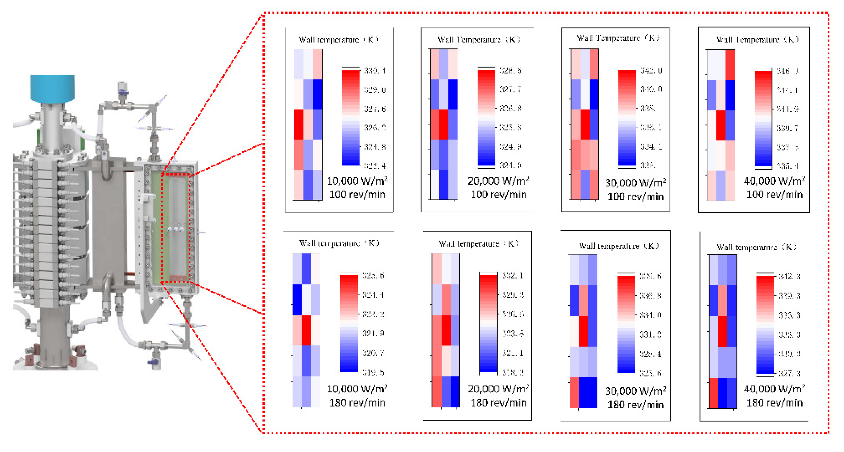
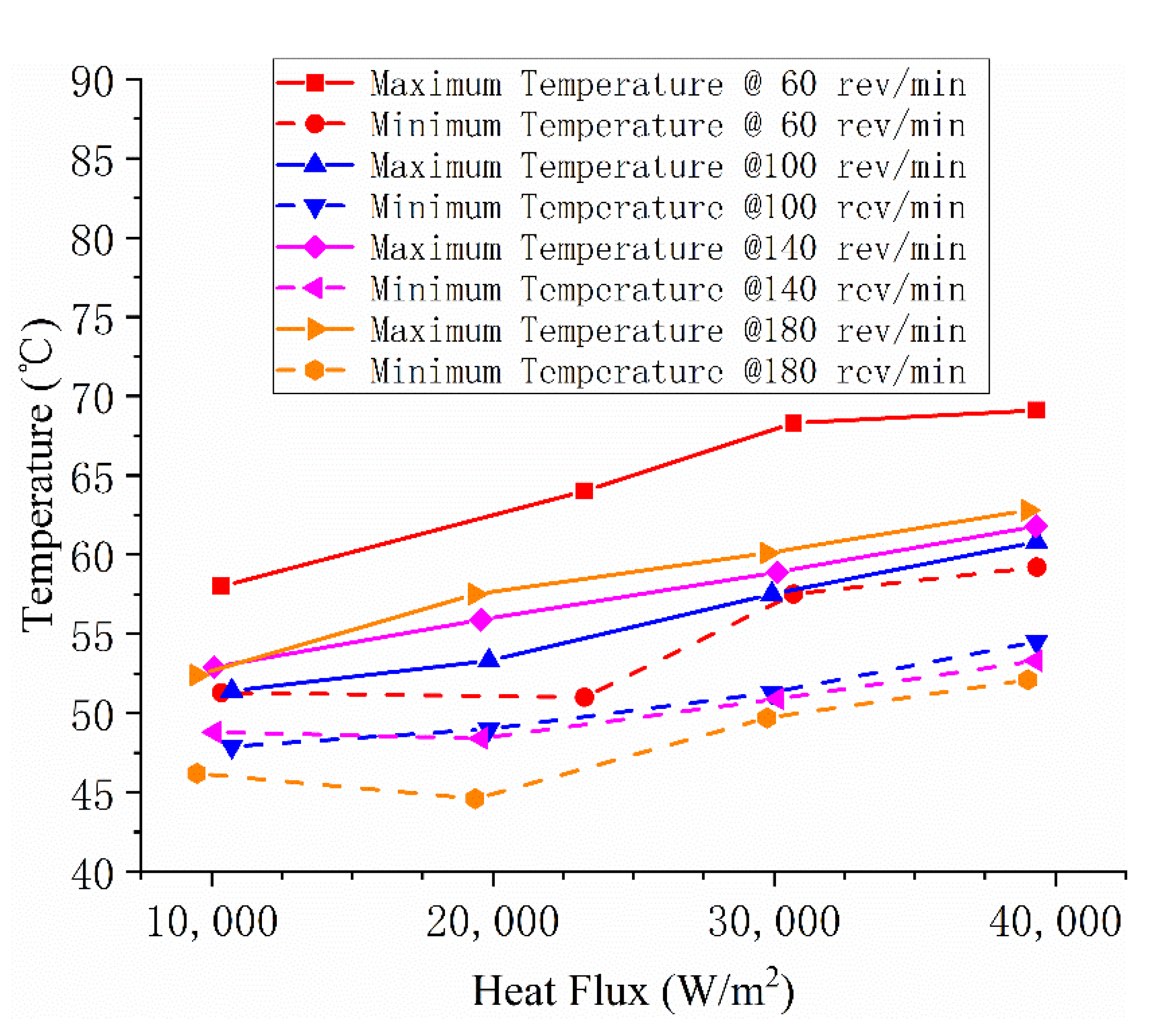
4.2.1. Characteristics of Temperature

In the phase change cooling stage, the amount of electrical power that can be dissipated is significantly improved. When the heat flux is 40,000 w/m2, the heating power reaches the experimental equipment limit, the maximum temperature of the 15 measuring points is only 69.1 °C. The temperature distribution on the heating plate at the maximum and minimum revolving speeds was plotted according to the measured values, see Figure 7. Each color block in the figure corresponds to a temperature measuring element. Starting from the bottom right is the 1# element, the top right is the 5# element, the bottom left is the 11# element and the top left is the 15# element. At the minimum speed, the effect of gravity cannot be ignored; the free liquid surface in the evaporator also maintains a tilt state, so the temperature distribution on the heating plate is not regular. At the maximum speed, the centrifugal acceleration is about 15 times the gravitational acceleration, and the radial distribution of the wall temperature is more obvious.
Figure 8 shows the curves of the maximum and minimum temperatures of the electric heating plate changing with the speed and heat flux. The wall temperature under the same heat load decreases with the increase of rotational speed.

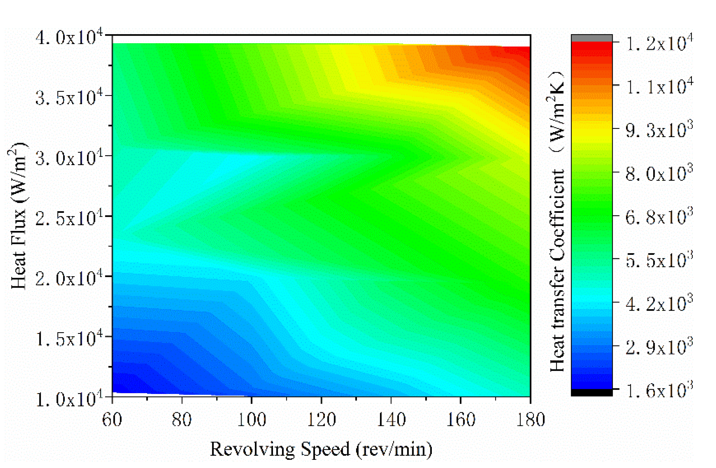
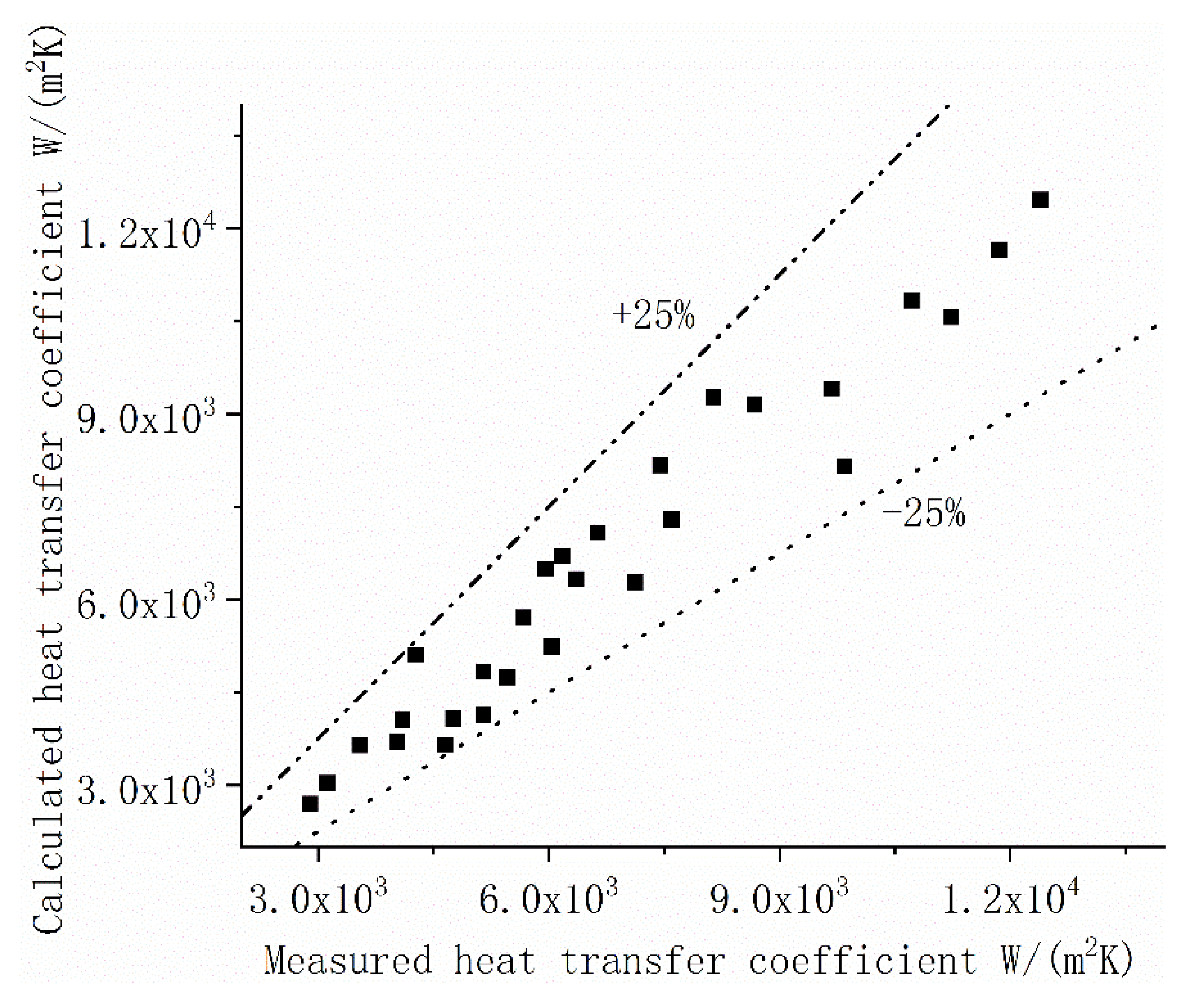
4.2.2. Calculation of Boiling Heat Transfer Coefficient

For boiling heat transfer, a superheated temperature is calculated based on saturation temperature. Two pressure sensors are arranged at point 3 and point 13 of the cover plate on the opposite side of the heating plate. Based on their measured pressure values, the saturation temperatures of these two points under different working conditions were queried. So, superheat as well as boiling heat transfer coefficient can be calculated. The contour showed in Figure 9 is the change trend of the boiling heat transfer coefficient with rotational speed and heat flux. Under the combined action of high rotational speed and high heat flux, the heat transfer coefficient can rise rapidly to 10,000 W/m2K.
The dimensionless numbers, such as Reynolds number (Re), Grashof Number (Gr), Froude number (Fr) and boiling number (Bo) as well as the density ratio between liquid and gas phases, are introduced into the calculation formula of Nusselt number (Nu), and the experimental results are used to conduct a nonlinear regression analysis of vertical wall boiling heat transfer under rotating state. The calculation formula is as follows:
Nu = 10.09445 Re 0.56342 Gr 0.56563 Pr 1.27142 Bo 0.52918 Fr 0.10526 ( ρ l ρ g ) 0.54633 .
Figure 10 shows that the boiling heat transfer coefficient calculated according to the above formula is stable with the experimental measured value, and the error is less than 25%.

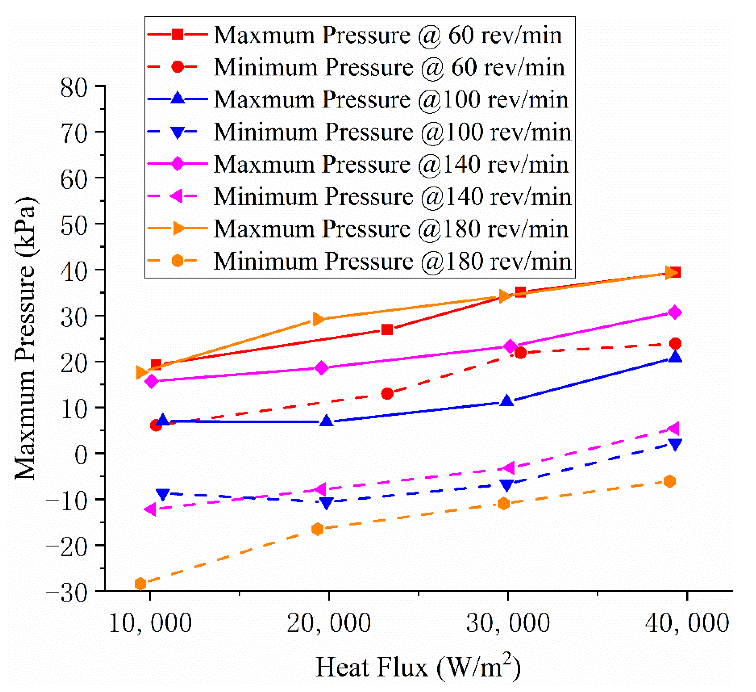
4.2.3. Characteristics of Pressure

As mentioned above, liquid cooling systems are concerned with pressure. The values of the highest and lowest pressures in the system are shown in Figure 11. Obviously, with the increase of revolving speed, the span of pressure distribution in the system becomes larger and larger. It can be seen that the higher the heat load, the higher the system pressure at the same speed; however, the maximum pressure of the same heat load does not rise synchronously with the increase of rotational speed. The reason is that the inlet pressure of condenser decreases with the increase of rotational speed when the heat load remains unchanged.

4.3. Advantages of Rotor Evaporative Cooling Systems

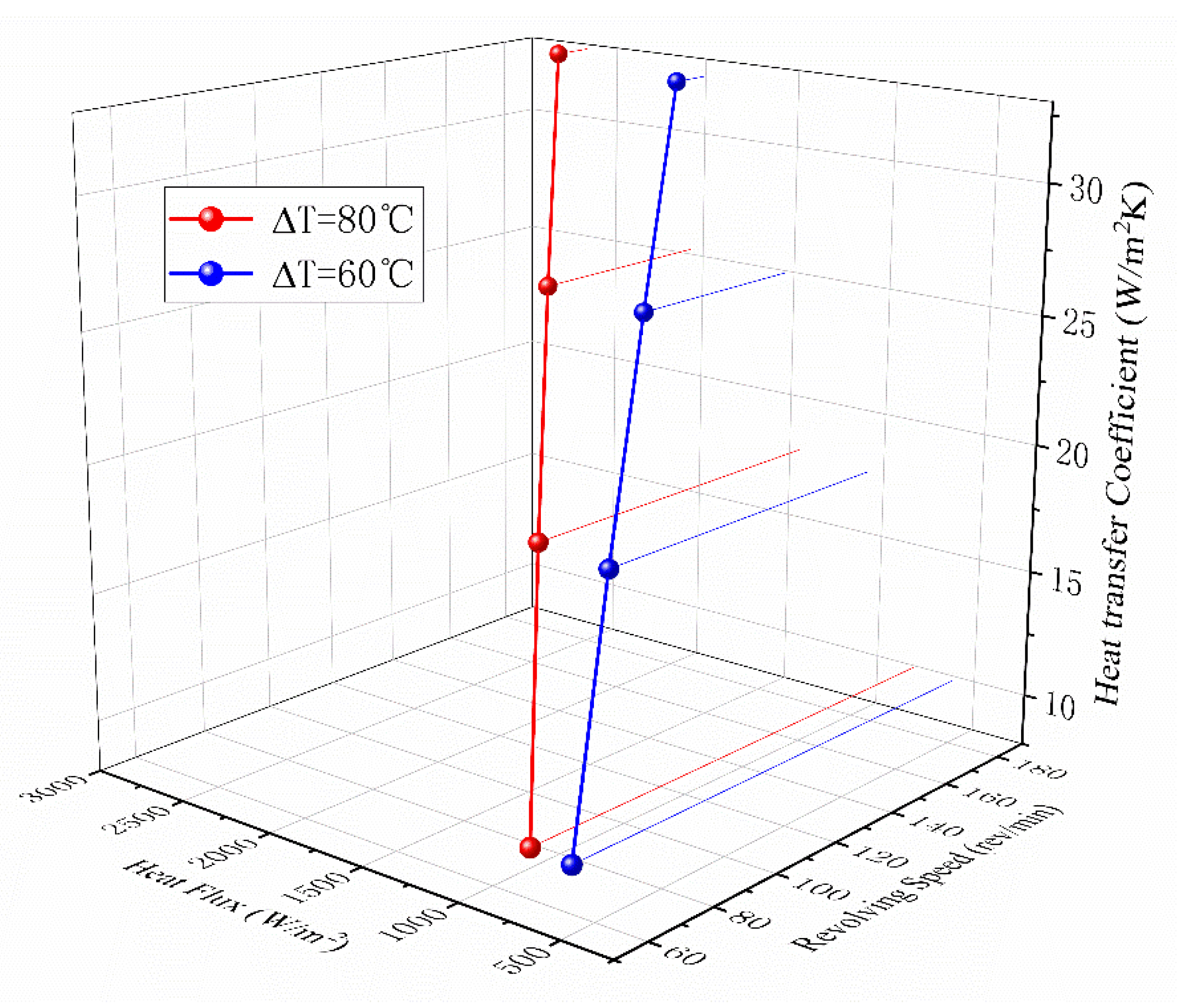
4.3.1. Large Heat Transfer Coefficient

By comparing Figure 6 with Figure 8 and Figure 9, it can be found that the temperature rise of the phase change cooling system is only one third of that of air-cooling when the heat load of the phase change cooling system is 10 times that of air-cooling. This is a huge advantage.
Only the outer surface of the magnetic pole coil is in contact with the cooling medium, such as air or the phase change cooling medium described in this paper, so its heat dissipation model can be approximated as a one-dimensional heat conduction problem with an internal heat source. The formula for calculating its surface heat flux can be obtained through simple derivation:
q = b f λ j 2 ,
in which b f is the width of the pole coil, λ is the electrical conductivity of the conductor, and j is the current density of the rotor.
Equation (9) shows that the heat flux on the pole surface is only related to the winding width and current density. The electromagnetic design and mechanical stress checking of the rotor cannot avoid the limitation of heat dissipation.
For example, the rotor flux leakage is closely related to the height of the pole body. If the stator design was not changed, the most effective way to reduce this height is to lower the pole coil. The role of the field winding is to provide a sufficient number of ampere-turns. When the number of ampere-turns remains unchanged, reducing the pole height means increasing the current density or width of winding, which results in increasing the heat flux density on the pole surface and improving the heat dissipation problem.
It can also be seen from Equation (9) that if the heat transfer coefficient between the coil and the coolant can be improved to carry more heat flux, so can the rotor current density be improved or the winding width be widened. The beneficial results are that the height of excitation winding can be reduced, the weight of the pole can be reduced and the flux leakage can be limited.
The heat transfer coefficient of the evaporative cooling system is two orders of magnitude higher than that of air-cooling, which is a good alternative.

4.3.2. Relatively Low Pressure

Consider a column of liquid. If the density and height of the liquid remain constant, the pressure at the bottom must increase as the acceleration increases. This problem is very prominent in water-cooled rotors. Additional efforts are needed to increase pipe strength and seal performance.
By observing Figure 11, again, it can be seen that the maximum pressure of the evaporative cooling system does not increase significantly with the increase of the rotational speed. In addition, under the same heat flux, the pressure in the condenser decreases with the increase of rotational speed. The reason behind these phenomena is that centrifugal force increases the driving force of the system circulation. The higher the speed, the greater the mass flow of the working medium, so that the evaporator outlet dryness decreased. The center of mass of the cooling medium in the whole circulation system then moves towards the rotating axis. This process inhibits the increase of the maximum static pressure. Based on this, the sealing difficulty of the rotor evaporative cooling system is much lower than that of the water cooling system. The tendency for pressure to decrease with revolving speed in condensers is not necessarily a good thing. Because the saturation temperature of a fluid corresponds to the pressure. The drop in condenser pressure means that the freezing point of the steam is lower. The decrease of the subcooling degree will reduce the efficiency of the condenser.

5. Conclusions

This paper presents a topology of a rotor evaporative cooling system and analyzes its principle. To verify the feasibility of the new cooling system, the research team built a rotating experimental platform. Compared with air-cooling, the following ideas were obtained:
  • A new concept for an evaporative cooling system for the rotor of the hydro generator is presented. Based on the analysis of principle, it can be used to maintain the temperature of the pole coil;
  • It is proved that the rotor evaporative cooling system can provide a much higher heat dissipation capacity. In the air-cooling test, the temperature rise of the heating plate is up to 80 °C under the heat flux of less than 2700 W/m2. In the phase change cooling test, the temperature rise is only 40–50 °C even if the heat flux increases to 40,000 W/m2;
  • A calculation formula of Nusselt number of vertical wall boiling heat transfer under a rotating state is obtained by nonlinear regression analysis. Under experimental conditions, the accuracy of the heat transfer coefficient can reach 25%;
  • The heat transfer coefficient of phase change cooling is up to 300 times that of air cooling. This has a good effect on reducing the height of the pole body, improving mechanical strength and reducing magnetic leakage;
  • The pressure of the rotor evaporative cooling system does not rise monotonously with the increase of rotational speed. This is very advantageous in terms of craftsmanship.
Limited by objective conditions, the centrifugal acceleration achieved by the experimental platform is only one tenth of that achieved by the real machine. In the future, it will be necessary to expand the research boundary through simulation analysis to study the feasibility of a rotor evaporative cooling scheme under a higher centrifugal force field.

Author Contributions

Conceptualization, Y.W.; methodology, L.R. and Y.W.; validation, L.R.; formal analysis, Y.W.; investigation, Y.W.; resources, Y.W.; data curation, Y.W.; writing—original draft preparation, Y.W.; writing—review and editing, L.R.; supervision, L.R.; project administration, L.R. All authors have read and agreed to the published version of the manuscript.

Funding

This research received no external funding.

Institutional Review Board Statement

Not applicable.

Informed Consent Statement

Not applicable.

Data Availability Statement

Not applicable.

Acknowledgments

Thanks to Li Ruiwei and Dai Honglin for their help in building the experimental platform.

Conflicts of Interest

The authors declare no conflict of interest.

Nomenclature

TTemperature difference between the hot wall surface and the coolant, °C
a c ( r ) Centrifugal acceleration, m/s2
b f Width of the pole coil
BoBoiling number
C f Velocity, m/s
FrFroude number
g Acceleration of gravity, m/s2
GrGrashof Number
h Heat transfer coefficient, W/(m2K)
jCurrent density, A/mm2
l Axial position, m
n r Revolving speed, rev/min
NuNusselt number
q Heat flux, W/m2
r Radial position, m
ReReynolds number
u Internal energy, J
v specific volume, m3/Kg
w i Work, J
α, βCorner markers used to represent the beginning and end of one stage
λ Electrical conductivity of the conductor, S/m
ρ l Liquid density, Kg/m3
ρ g Gas density, Kg/m3

References

  1. Torriano, F.; Stella, S.; Jayet, Y.; Ardaillon, T.; Charest-Fournier, J.P.; Hudon, C.; Merkhouf, A.; Guillot, E. Numerical and Experimental Study of the Ventilation in an Operating Hydrogenator. In Proceedings of the International Conference on Numerical Analysis and Applied Mathematics (ICNAAM-2018), Rhodes, Greece, 13–18 September 2018. [Google Scholar]
  2. Foster, E.N.; Parker, F.J. Hydroelectric Machines. IEE Proc. C Gener. Transm. Distrib. 1986, 133, 126–136. [Google Scholar] [CrossRef]
  3. Schafer, D. The world’s largest fully water-cooled hydro generators in the Bieudron power plant (Switzerland). In Proceedings of the IEMDC’99—IEEE International Electric Machines and Drives Conference, Seattle, WA, USA, 9–12 May 1999; pp. 827–829. [Google Scholar]
  4. Traxler-Samek, G.; Zickermann, R.; Schwery, A. Advanced Calculation of Temperature Rises in Large Air-Cooled Hydro-Generators. In Proceedings of the ICEM: 2008 International Conference on Electrical Machines, Vilamoura, Portugal, 6–9 September 2008; pp. 856–861. [Google Scholar]
  5. Zhang, Q.; Yan, J.; Wang, M.; Chen, Z. Numerical Simulation on Ventilation and Cooling of Hydro-Generator. In Proceedings of the Power and Energy Engineering Conference 2010, Wuhan, China, 11–12 September 2010; p. 277. [Google Scholar]
  6. Han, J.; Ge, B.; Tao, D.; Zhao, H.; Xiao, F.; Li, W. Calculation and analysis of complex fluid flow and thermal fields in a fully air-cooled hydrogenerator. Int. J. Therm. Sci. 2017, 116, 278–286. [Google Scholar]
  7. Li, W.; Zhang, Y.; Chen, Y. Calculation and Analysis of Heat Transfer Coefficients and Temperature Fields of Air-Cooled Large Hydro-Generator Rotor Excitation Windings. IEEE Trans. Energy Conv. 2011, 26, 946–952. [Google Scholar]
  8. Li, D.; Li, W.; Li, J.; Liu, X. Analyzing regularity of interpolar air motion and heat dissipation coefficient distribution of a salient pole synchronous generator considering rotary airflow. Int. Commun. Heat Mass Transf. 2020, 119, 104828. [Google Scholar] [CrossRef]
  9. Li, W.; Zhou, F.; Hou, Y.; Cheng, S.K. Calculation of rotor temperature field for hydro-generator as well as the analysis on relevant factors. Proc. Chin. Soc. Electr. Eng. 2002, 22, 85–90. [Google Scholar]
  10. Li, W.; Li, D.; Li, J. Analysis of hydro-generator rotor coupling field on rotor ventilation duct blocked. Electr. Mach. Control 2017, 21, 30–38. [Google Scholar]
  11. Li, W.; Chen, Y.; Huo, F.; Zhang, Y. Fluid Flow and Temperature Field Analysis between Two Poles of a Large Air-cooled Hydro-Generator Rotor in Rotation. Proc. Chin. Soc. Electr. Eng. 2012, 32, 132–139. [Google Scholar]
  12. Li, W.; Li, D.; Li, J.; Zhang, X. Influence of Rotor Radial Ventilation Ducts Number on Temperature Distribution of Rotor Excitation Winding and Fluid Flow State between Two Poles of a Fully Air-Cooled Hydro-Generator. IEEE Trans. Ind. Electron. 2017, 64, 3767–3775. [Google Scholar] [CrossRef]
  13. Cravero, C.; Leutcha, P.J.; Marsano, D. Simulation and Modeling of Ported Shroud Effects on Radial Compressor Stage Stability Limits. Energies 2022, 15, 2571. [Google Scholar] [CrossRef]
  14. Jamshidi, H.; Nilsson, H.; Chernoray, V. Experimental and numerical investigation of hydro power generator ventilation. In Proceedings of the 27th IAHR Symposium on Hydraulic Machinery and Systems (IAHR 2014), Montreal, QC, Canada, 22–26 September 2014. [Google Scholar]
  15. Majer, S.; Tukovic, Z. Numerical Study of Windage Power Loss for One Salient Pole Hydro Generator. In Proceedings of the 2020 International Conference on Electrical Machines (ICEM), Gothenburg, Sweden, 23–26 August 2020; Volume 1, pp. 2624–2630. [Google Scholar]
  16. Gu, G.B.; Ruan, L. A few questions about using the evaporative cooling method as the substitute for the water-cooling method in the three gorges’ hydro-generator. In Proceedings of the ICEMS 2005: Eighth International Conference on Electrical Machines and Systems, Nanjing, China, 27–29 September 2005; Volume 1, pp. 7–11. [Google Scholar]
  17. Gu, G.; Ruan, L. Applications and Developments of the Evaporative Cooling Technology in the Field of Hydrogenerators. Proc. Chin. Soc. Electr. Eng. 2014, 34, 5112–5119. [Google Scholar]
  18. Yuan, J.; Gu, G.; Ruan, L.; Tian, X.; Duo, L.; Zhang, T. Applied Engineering Design of Three Gorges’ 840MVA Hydro-generator with Close Loop Self Circulating Evaporative Cooling System. In Proceedings of the ICEMS 2008: 11th International Conference on Electrical Machines and Systems, Wuhan, China, 17–20 October 2008; p. 142. [Google Scholar]
  19. Ruan, L.; Gu, G.; Tian, X.; Chang, Z. Experimental research of new coolant in evaporative cooling technique of large generators. Adv. Technol. Electr. Eng. Energy 2002, 21, 21–24. [Google Scholar]
  20. Ruan, L.; Gu, G.; Tian, X. Experiment on Two-Phase Flowing Pressure Drop in the Evaporative Cooling System of Hydro-Generators. J. Tianjin Univ. 2005, 38, 27–30. [Google Scholar]
  21. Dong, H.; Ruan, L.; Guo, S. Operating Characteristics of Different Inner Evaporative Cooling Systems of Generators. In Proceedings of the 18th International Conference on Electrical Machines and Systems (ICEMS), Pattaya, Thailand, 25–28 October 2015; pp. 1097–1100. [Google Scholar]
  22. Dong, H.; Ruan, L. Research on Loop Resistance in Self-circulation Evaporative Cooling System of Stator Collector Ring of Hydro-generator. In Proceedings of the 2013 International Conference on Electrical Machines and Systems (ICEMS), Busan, Korea, 26–29 October 2013; pp. 1437–1440. [Google Scholar]
  23. Xiong, B.; Gu, G.; Ruan, L.; Li, Z.; Fu, D.; Cao, R.; Guo, S.; Gao, J. Improvement of Inner Evaporative Cooling Experiment Model for Large Turbo Generator Stator Bars. In Proceedings of the 2013 International Conference on Electrical Machines and Systems (ICEMS), Busan, Korea, 26–29 October 2013; pp. 101–104. [Google Scholar]
  24. Dong, H.; Ruan, L. Research on the Temperature Distribution of Stator Collector Ring in Evaporative Cooling Hydro-generator. Electr. Power Energy Syst. 2012, 516–517, 1622–1625. [Google Scholar] [CrossRef]
  25. Liu, F.; Ruan, L.; Li, Z.; Guo, S. The Calculation on the Coolant Temperature of the Condenser outlet in the Evaporative Cooling System of the Hydro-generator. In Proceedings of the 2013 International Conference on Electrical Machines and Systems (ICEMS), Busan, Korea, 26–29 October 2013; pp. 87–90. [Google Scholar]
  26. Ruan, L.; Gu, G. Technical feasibility research of application of evaporative cooling technique to large Three Gorges’ hydrogenerators—The selection of material and the size for the hollow conductors in the stator windings. J. Harbin Inst. Technol. 2005, 37, 401–404. [Google Scholar]
  27. Ruan, L.; Gu, G.; Tian, X.; Chang, Z.; Yuan, J. Analysis of the key techniques in hydro-generator with inner evaporative cooling. In Proceedings of the ICEMS 2003: Sixth International Conference on Electrical Machines and Systems, Beijing, China, 9–11 November 2003; Volume 1, pp. 14–16. [Google Scholar]
  28. Liu, F.; Ruan, L.; Li, Z. The Calculation on the Coolant Dryness of the Hollow Conductor Outlet in the Evaporative Cooling System of the Hydro-generator. In Proceedings of the 2013 International Conference on Electrical Machines and Systems (ICEMS), Busan, Korea, 26–29 October 2013; pp. 91–94. [Google Scholar]
  29. Ruan, L.; Chen, J.; Gu, G. Comparison and analysis of stator’s air cooling and evaporative cooling method of 1000MW hydrogenerators. Adv. Technol. Electr. Eng. Energy 2014, 33, 1–6. [Google Scholar]
  30. Gu, G.; Ruan, L.; Liu, F.; Xiong, B. Developments, Applications and Prospects of Evaporative Cooling Technology. Transa. China Electrotech. Soc. 2015, 30, 1–6. [Google Scholar]
  31. Zhi, L.; Lin, R. Design for gas-liquid-solid stator insulation system in the evaporative cooling turbogenerator. Electr. Mach. Control 2018, 22, 77–84. [Google Scholar]
  32. Zhi, L.; Lin, R. Theoretical Analysis and Experimental Verification on Mathematical and Physical Model of Gas-Liquid-Solid Insulation System. Trans. China Electrotech. Soc. 2018, 33, 2097–2104. [Google Scholar]
  33. Yao, T.; Hou, Z.; Gu, G. Application of evaporative cooling technique to large turbo generator. Trans. China Electrotech. Soc. 2008, 23, 1–6. [Google Scholar]
Figure 1. The structure of the pole with evaporative cooling.
Processes 10 00934 g001
Figure 2. The schematic of rotor evaporative cooling system.
Processes 10 00934 g002
Figure 3. The Schematic of experimental device.
Processes 10 00934 g003
Figure 4. The structure of one cover.
Processes 10 00934 g004
Figure 5. The distribution of temperature sensors.
Processes 10 00934 g005
Figure 6. The heat transfer coefficient of air-cool stage.
Processes 10 00934 g006
Figure 7. Comparison of wall temperature distribution.
Processes 10 00934 g007
Figure 8. Change of temperature extremums with revolving speed and heat flux.
Processes 10 00934 g008
Figure 9. The boiling heat transfer coefficient.
Processes 10 00934 g009
Figure 10. The calculated heat transfer coefficients agree with the measured ones.
Processes 10 00934 g010
Figure 11. Change of pressure extremums with revolving speed and heat flux.
Processes 10 00934 g011
Table 1. Summary of measurement devices.
DeviceRangeAccuracy
Speed measuring instrument0~500 rpm0.25%
AC voltage transmitter0~5 V0.5%
AC current transmitter0~200 A0.5%
RTD0~200 °CA level
Micro Pressure Sensor−50~100 kPa0.1%
Table 2. The control variables their ranges.
VariableUnitValue
Air-CoolingEvaporate-Cooling
Revolving Speedrev/min18060.0100140180
Heat FluxW/m2Adjust the value so that the wall temperature reaches the value of 100 °C10,00020,00030,00040,000
Publisher’s Note: MDPI stays neutral with regard to jurisdictional claims in published maps and institutional affiliations.

