Article

Theoretical Analysis of the Micro Annulus of an Oil-Well Cement Sheath Formed via Cooling under Acid-Fracturing Conditions

1
State Key Laboratory of Oil and Gas Reservoir Geology and Exploitation, Southwest Petroleum University, Chengdu 610500, China
2
Petroleum Engineering School, Southwest Petroleum University, Chengdu 610500, China
3
Institute of Subsurface Energy Systems, Clausthal University of Technology, 38678 Clausthal-Zellerfeld, Germany
4
School of Sciences, Southwest Petroleum University, Chengdu 610500, China
*
Authors to whom correspondence should be addressed.
Processes 2022, 10(5), 966; https://doi.org/10.3390/pr10050966
Submission received: 6 April 2022 / Revised: 5 May 2022 / Accepted: 7 May 2022 / Published: 11 May 2022
(This article belongs to the Special Issue Oil and Gas Well Engineering Measurement and Control)

Abstract

:
The plastic deformation and interface micro annulus of oil-well cement during acid fracturing are key reasons for the failure of the wellbore seal and sustained casing pressure. However, most of the existing research ignores the influence of the wellbore cooling effect during acid fracturing, owing to which, the design conditions in the theoretical analysis may be inconsistent with those of the actual wellbore, and the calculation results may be biased. In this study, a novel elastoplastic mechanical model of the cement sheath was established. This model can analyze the yield state of the cement sheath under the influence of three-dimensional principal stress and consider the effect of the differential temperature stress on the interface debonding of the cement sheath from the beginning to the end of acid fracturing. Moreover, the generation mechanism and development law of the interface micro annulus were clarified. The findings indicated that the influence of the intermediate principal stress cannot be ignored; otherwise, the elastoplastic analysis results of the cement sheath may be conservative. During acid fracturing, the casing–cement sheath interface is influenced by the differential temperature stress, and the interface is debonded; however, a micro annulus is not generated. The debonding of the cement sheath–formation interface and micro annulus occurs only when the cement sheath is completely plastic. After acid fracturing, the interface micro annulus is likely to be generated at the casing–cement sheath interface, and the presence of the differential temperature stress may increase the formation risk of the interface micro annulus. The research results can provide theoretical guidance for the prediction of oil-well cement sheath interface seals under acid-fracturing conditions.

1. Introduction

Cementing, as a key process in the construction of oil and gas wells [1], is aimed at injecting cement slurry into the annular between the casing and formation and ensuring its solidification within a specified time to form a cement sheath [2,3]. To avoid wellbore integrity issues such as wellbore sealing failure, formation fluid channeling, and casing damage, the cement sheath must maintain adequate isolation under the load induced by the wellbore construction operation [4,5,6]. Notably, the failure of cement sheath sealing during the well construction cycle has not been completely clarified [7]. For example, in an oil field in western China, the high-temperature and high-pressure gas well is often subjected to sustained casing pressure (SCP) after acid fracturing, which critically threatens the safety of the ground personnel, equipment, and environment [8,9]. Early studies highlighted that the plastic yield of the cement sheath under high pressure in a wellbore and the generation of the interface micro annulus are key causes of SCP [10,11,12].
Extensive research has been performed on the micro annulus at the cement sheath interface. Goodwin and Crook [13] considered a full-size casing and cement sheath test device to experimentally analyze the failure mode of the cement sheath. The authors reported that under steam–flood injection conditions, the cement sheath interface maybe lose its sealing and annular control of gas or water. Andrade et al. [14,15,16] applied a cyclic temperature load to the casing–cement sheath–formation combination and noted that the interface of the cement sheath is influenced by the temperature and debonded. Zeng et al. [17] established a wellbore simulation device and applied cyclic loads to the cement sheath to simulate the failure of the cement sheath under large-scale hydraulic fracturing conditions. Under cyclic loading, the cement sheath is expected to undergo cumulative plastic deformation, and an interface micro annulus is expected to be formed. Li et al. [18] conducted equivalent physical experiments based on a self-developed wellbore simulation device and observed that the cement sheath enters a plastic state under high internal casing pressure conditions, and interface debond occurs during the unloading stage, eventually leading to gas channeling.
In addition to experimental methods, several scholars have established theoretical models to predict whether the cement sheath generates a micro annulus under wellbore loads. Mueller et al. [19] used the finite element method to analyze the micro annulus of the cement sheath and noted that temperature changes lead to the bonding failure of the interface. Chu et al. [20] used the Mohr–Coulomb criterion as the yield criterion to establish an elastoplastic mechanical model of the cement sheath, and based on Jackson’s experimental parameters, evaluated the size of the micro annulus generated at the cement sheath interface during the unloading stage. Dusseault et al. [21] and Taleghani et al. [22] also highlighted that the cement sheath may produce an interface micro annulus under cycling temperature and pressure conditions. Through theoretical analysis of the failure mode of the cement sheath of gas storage wells, Zhang et al. [23] indicated that the interface debonding and micro annulus generation occurs when the interface tensile stress is greater than the bonding strength during the unloading stage. Chen et al. [24] noted that when the cement sheath completely enters the plastic state, a larger micro annulus may be generated when the internal casing pressure decreases. They recommended the limitation of the phenomenon of the wellbore cement sheath completely entering the plastic state. Zhao et al. [25] reported that the decrease in the temperature in the wellbore during fracturing influences the stress distribution of the cement sheath and may lead to tensile failure of the cement sheath.
According to the abovementioned studies, a cement sheath is expected to undergo plastic deformation under the influence of the internal casing pressure and generate a micro annulus during the unloading stage. In addition, temperature changes are expected to adversely influence the cement sheath interface bonding. In the actual wellbore operation, as shown in Figure 1, the temperature and pressure change during the acid-fracturing are the most severe. Acid-fracturing refers to the process of artificially creating fractures in the formation by pumping the acid-fracturing fluid into the formation, which can effectively improve the seepage characteristics of the formation. Due to the pumping of the acid fracturing fluid, the temperature in the wellbore will decrease continuously and the wellbore pressure will increase rapidly. At this time, the cement sheath will withstand both the wellbore cooling effect and high internal casing pressure. However, in existing research, the actual conditions of “high-pressure expansion” and “cooling contraction” of the cement sheath during acid-fracturing have been neglected; in particular, the influence of the cooling effect in the acid-fracturing process on the cement sheath interface and micro annulus. Therefore, the theoretical analysis results may deviate from the actual wellbore. Notably, the oil and gas industry lack an elastoplastic mechanical model of oil-well cement that can consider the acid-fracturing conditions and integrate the effects of the wellbore pressure loads and cooling phenomena.
Considering these aspects, this study was aimed at establishing an elastoplastic model that can describe the mechanical integrity of the cement sheath under acid-fracturing conditions. The proposed model can analyze the yield state of the cement sheath under the influence of three-dimensional principal stress and consider the effect of the differential temperature stress generated by the wellbore cooling on the cement sheath interface debonding and micro annulus generation from the beginning to the end of acid fracturing. The accuracy and effectiveness of the elastoplastic model were validated through a comparison with the elastoplastic analysis results of cement sheaths associated with Chu and Jackson [20]. In addition, based on the wellbore conditions of a high-temperature and high-pressure gas well, the generation mechanism and development law of the cement sheath micro annulus during and after the acid-fracturing process were clarified. The proposed model was expected to effectively restore the stress state of the cement sheath under acid-fracturing conditions and ensure that the analysis results of the cement sheath interface debonding and micro annulus more accurately represented the state of actual wellbores.

2. Model Establishment

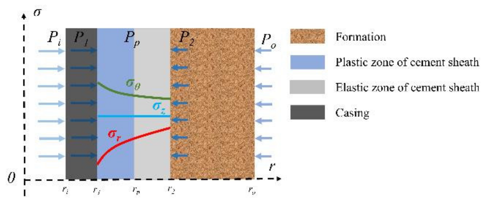
2.1. Mechanical Model of Casing–Cement Sheath-Formation

To establish the elastoplastic model of the cement sheath, the following assumptions are implemented [20]:
  • The casing and formation are elastomers, the cement sheath is an elastoplastic material, and the yield condition of the cement sheath satisfies the twin-shear unified strength theory;
  • The casing, cement sheath, and formation correspond to homogeneous and isotropic materials;
  • The casing is centered, and the cementing quality is good.
Tensile stress and compressive stress are defined as normal and negative stresses, respectively. Because the radial stress at the inner wall of the cement sheath is always greater than that at the outer wall, the inner wall of the cement sheath yields first as the internal casing pressure increases during acid fracturing. With the gradual expansion of the plastic zone of the cement sheath, the cement sheath can be divided into a plastic zone and an elastic zone. When the pressure reaches a critical value, the cement sheath enters the plastic state. The case in which the casing, formation, and cement sheath are in the elastoplastic state is illustrated in Figure 2.
where σr, σθ, and σz represent the radial, circumferential, and axial stresses (MPa), respectively. Pi, P1, Pp, P2, and Po represent the internal casing pressure, casing–plastic cement sheath interface contact pressure, plastic cement sheath–elastic cement sheath interface contact pressure, elastic cement sheath-formation interface contact pressure, and formation pressure (MPa), respectively. ri, r1, rp, r2, and ro represent the radius of the casing inner wall, plastic cement sheath inner wall (casing outer wall), plastic–elastic interface of cement sheath, elastic cement sheath outer wall (formation inner wall), and formation outer wall (mm), respectively. The 0 represents the origin of coordinates. r represents the distance from the center of the wellbore (mm). σ represents the magnitude of stress (MPa).

2.1.1. Stress and Displacement Analysis of the Plastic Cement Sheath

The cement sheath is divided into the plastic and elastic zones, and the zones are separately discussed. The plastic zone cement sheath is represented as the area pertaining to r1rrp in Figure 2. Because the cement sheath bears radial, circumferential, and axial stresses in the wellbore, the twin-shear unified strength theory considering the three-dimensional principal stress is selected to define the yield criterion for the plastic zone of the cement sheath [26]. The relevant theoretical equations are
F = 1 α σ 1 1 1 + b b σ 2 + σ 3 = σ c σ 2 σ 1 + α σ 3 1 + α F = 1 α 1 + b σ 1 + b σ 2 σ 3 = σ c σ 2 σ 1 + α σ 3 1 + α
where σ1, σ2, and σ3 represent the maximum, intermediate, and minimum principal stresses (MPa), respectively. σc represents the yield strength (MPa). α and b represent the tensile-compression strength ratio (MPa) of the material and weight coefficient used to reflect the influence of the intermediate principal stress, respectively. b can be defined as
b = 1 + α B B 1
where B denotes the tensile-shear strength ratio (MPa).
When the wellbore cement sheath bears the load from the formation and casing, radial and circumferential compressive stresses are distributed over the cement sheath (it may also be tensile stress in the circumferential direction), with the radial compressive stress being significantly larger than the circumferential stress. Because σ1σ2σ3, it can be considered that σ1 = σθ > (or <) 0, σ2 = σz = (σr + σθ)/2, and σ3 = σr <0. Moreover, the tensile-compression strength ratio of cement materials must be less than 1, so (σr + σθ)/2 = σ2 ≤ (σθ + ασr)/(1 + α), which is consistent with the first expression in Equation (1), and the yield condition can be defined as
2 + 2 b α b 2 α 1 + b σ θ b + 2 2 1 + b σ r = σ c
Furthermore, the stress components of the cement sheath in the radial and circumferential satisfy the balance equation:
d σ r d r + σ r σ θ r = 0
Considering Equations (3) and (4) and the boundary conditions r = r1 and σr = −p1, the stress distribution equations for the plastic zone of the cement sheath can be solved:
σ r = α 1 α σ c r 1 r 2 + 2 b 2 b α 2 α 2 + 2 b b α p 1 + α σ c 1 α σ θ = α 1 α σ c 2 α + b α 2 + 2 b b α r 1 r 2 + 2 b 2 b α 2 α 2 + 2 b b α p 1 + α σ c 1 α
Considering the boundary conditions r = rp and σr = −p1, the contact pressure of the elastoplastic interface of the cement sheath can be determined:
p p = r 1 r p 2 + 2 b 2 b α 2 α 2 + 2 b b α p 1 + α σ c 1 α α 1 α σ c
Neglecting the plastic cement sheath volumetric strain according to the law of volume elasticity
ε r + ε θ = 1 + v 1 2 v E σ r + σ θ
where εr and εθ represent the radial and circumferential strains, respectively. E represents the Young’s modulus (MPa). v represents the Poisson’s ratio.
According to the geometry equation,
ε r = d u d r ε θ = u r
where u represents the displacement (mm).
By substituting Equations (5) and (8) into Equation (7), the displacement of the plastic zone ucp of the cement sheath can be determined as
u c p = 1 + v c 1 2 v c E c α σ c 1 α r p 1 + α σ c 1 α r 1 2 + 2 b 2 b α 2 α 2 + 2 b b α r 2 α + b α 2 + 2 b b α + K r
where ucp denotes the displacement of the plastic cement sheath (mm). Ec represents the Young’s modulus of the cement sheath (MPa). vc represents the Poisson’s ratio of the cement sheath. K is the integral constant, which is an unknown quantity, and r corresponds to any radial position in the plastic zone (mm). The displacement at the outer boundary of the plastic zone of the cement sheath can be defined as:
u c p i = 1 + v c 1 2 v c E c p 1 r 1 + K r 1
u c p o = 1 + v c 1 2 v c E c α σ c 1 α r p p 1 + α σ c 1 α r 1 2 + 2 b 2 α b 2 α 2 + 2 b b α r p 2 α + b α 2 + 2 b b α + K r p
where ucpi and ucpo denote the displacements of the inner and outer walls of the cement sheath plastic zone (mm), respectively.

2.1.2. Stress and Displacement Analysis of the Elastic Cement Sheath

The elastic zone of the cement sheath can be evaluated considering the Lame formula [27] for elastic mechanics. The elastic zone in Figure 2 refers to the area corresponding to rprr2. The pressure of the elastic inner wall and outer wall is pp and p2, respectively. In this manner, the expressions for the radial stress σrc and circumferential stress σθc of the cement sheath can be derived:
σ r c = r 2 2 p 2 p p r 2 2 r p 2 + r p 2 p p r 2 2 p 2 r 2 2 r p 2 σ θ c = r 2 2 p p p 2 r 2 2 r p 2 + r p 2 p p r 2 2 p 2 r 2 2 r p 2
In addition, the radial stress at the boundary and elastic-–plastic interface in the elastic zone satisfies the yield criterion. Thus, the equation for the contact pressure p2 of the cement sheath-formation interface can be defined as
p 2 = 1 r 2 2 2 + 2 b α b 1 α + b α b r p 2 + 1 + α + b r 2 2 p p α 1 + b r 2 2 r p 2 σ c
The radial displacement at the inner and outer boundaries of the elastic zone of the cement sheath can be determined through the theoretical displacement formula of the thick-walled cylinder [27]:
u c e i = 1 2 ν c r p 3 + 1 + v c r p r 2 2 E c r 2 2 r p 2 p p 2 ν c r p r 2 2 E c r 2 2 r p 2 p 2
u c e o = 2 ν c r p 2 r 2 E c r 2 2 r p 2 p p 1 2 ν c r 2 3 + 1 + v c r p 2 r 2 E c r 2 2 r p 2 p 2
where ucei and uceo denote the boundary displacement of the inner and outer elastic zone (mm), respectively.

2.1.3. Continuity Condition and Model Solution

Because the casing, cement sheath, and formation are in close contact, under the action of the casing pressure and formation pressure, the displacement of the outer wall of the casing (uso) is equal to that of the inner wall of the cement sheath, and the displacement of the outer wall of the cement sheath is equal to that of the inner wall of the formation (ufi). The displacements at the elastic–plastic boundary of the cement sheath are also equal [20]. This state corresponds to the continuity condition of the casing–elastic–plastic cement sheath-formation combination, which can be characterized by the following equations:
u s o = u c p i u c p o = u c e i u c e o = u f i
where:
u s o = 1 E s r 1 2 r i 2 1 2 ν s r i 2 p i r 1 2 p 1 r 1 + 1 + ν s r i 2 r 1 2 p i p 1 1 r 1
u f i = 1 E f r o 2 r 2 2 1 2 ν f r 2 2 p 2 r o 2 p o r 2 + 1 + ν f r 2 2 r o 2 p 2 p o 1 r 2
where Es and Ef denote the Young’s modulus of the casing and the formation (MPa), respectively, and vf denotes the Poisson’s ratio of the casing and the formation, respectively.
By combining Equation (16) with Equations (6) and (13) and substituting the values of the casing, cement sheath, and formation sizes, the mechanical properties, internal casing pressure, and formation pressure, as well as the unknowns p1, pp, p2, rp, and K, can be determined. Thus, the stress and displacement at any position inside the casing–elastic–plastic cement sheath-formation combination can be determined.

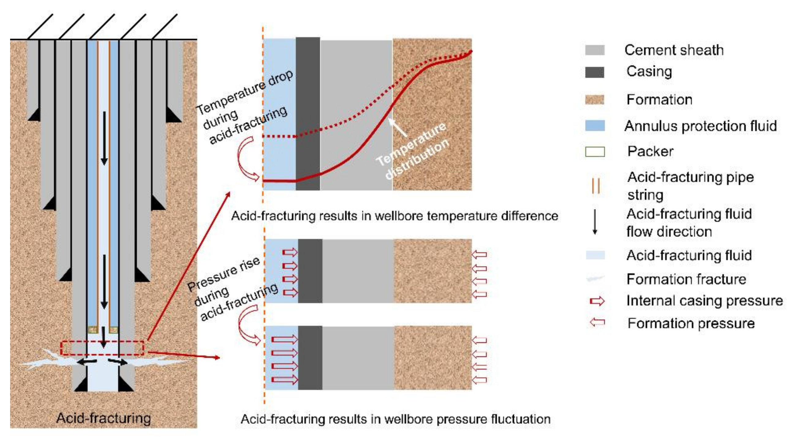
2.2. Differential Temperature Stress Model of Casing–Cement Sheath-Formation

The differential temperature stress of the casing, cement sheath, and formation can be solved using elastic mechanics [28]. The corresponding model and solution method are presented in Appendix A; in cases 1–3, the cement sheath is in the elastic state, elastic–plastic state, and plastic state, respectively.

2.3. Combined Stress Calculation Model of Casing–Cement Sheath-Formation

Under the combined influence of the wellbore temperature change and acid fracturing, the casing–cement sheath-formation combination simultaneously bears the differential temperature stress and pressure load, and the superposition of the two loads correspond to the combined stress:
σ r = σ r + σ r t σ θ = σ θ + σ θ t
where σ and σt represent the stresses caused by the wellbore pressure and the temperature difference of the wellbore (MPa), respectively. Subscript r and θ denote radial and circumferential directions, respectively.
During acid fracturing, the wellbore load is rapidly transmitted to the bottom of the well. As construction progresses, the temperature at the bottom of the well gradually decreases. Therefore, in the calculation, first, the elastic–plastic interval of the cement sheath and interface contact pressure must be analyzed according to the wellbore load. Subsequently, the differential temperature stress calculation methods must be identified according to the elastic–plastic interface position. Finally, the stress and displacement must be superimposed under the influence of the fracturing load. The combined stress and displacement of the casing–cement sheath-formation combination can thus be determined.

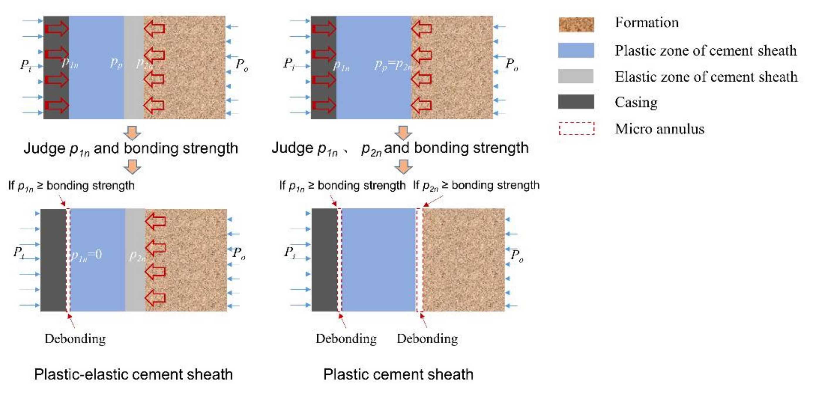
2.4. Calculation of Micro Annulus during Acid Fracturing

During acid fracturing, the cement sheath is simultaneously subjected to high pressure and cooling effects. When the temperature decreases, the cement sheath undergoes “chilling shrinkage”, which may lead to the generation of radial tensile stress at the interface. If the cement sheath is in a plastic state, a micro annulus may be generated. Therefore, a calculation method for the micro annulus in the acid-fracturing process is established, considering the casing–cement sheath interface as an example.
Considering the assumption specified in Section 2.1, the highest casing pressure is defined as pim, and the pressure values of the inner wall, elastic–plastic interface, and outer wall of the cement sheath are pp1m, ppp, and pp2m, respectively. During acid fracturing, the pressure in the casing remains constant. Changes in the size of the casing–cement sheath-formation combination and position of the elastic–plastic interface of the cement sheath under the above-mentioned wellbore load conditions are identified.
The displacement of the casing inner wall, usim, under the action of the internal casing pressure and the formation pressure can be expressed as:
u s i m = 1 + v s E s r 1 2 r i + 1 2 v s r i 3 r 1 2 r i 2 p i m 1 + v s E s 2 1 v s r 1 2 r i r 1 2 r i 2 p 1 m p
The displacements of the inner wall of the casing, inner and outer walls of the cement sheath, and the elastic–plastic boundary have been specified in Section 2.1. The displacement of the formation outer wall ufom under the acid-fracturing load is expressed as
u f o m = 1 + v f E f 2 1 v f r 2 2 r o r o 2 r 2 2 p 2 m p 1 + v f E f r 2 2 r o + 1 2 v f r o 3 r o 2 r 2 2 p o
By setting the wellbore size as the initial wellbore size, the method described in Section 2.2 is used to calculate the differential temperature stress. Before acid fracturing is initiated, the temperature in the wellbore is constant, which also represents the formation temperature. The differential temperature stress is zero. As the acid fracturing is initiated, the temperature in the wellbore gradually decreases. At the moment when the wellbore temperature is at its lowest, the temperatures of the inner and outer walls of the casing are recorded as t1m and t2m, respectively. The temperatures of the inner and outer walls of the formation are recorded as t3m and t4m, respectively, and the temperature at the elastic-plastic interface of the cement sheath is defined as tpm.
When the wellbore temperature is minimized, the cement sheath interface exhibits sufficient bonding strength. Moreover, the casing–cement sheath-formation combination is in close contact, and thus, the displacement continuity condition is satisfied. According to Appendix A, the radial stress at the inner and outer walls of the cement sheath and elastic–plastic interface can be calculated:
σ 1 m t = E c p C 1 c p 1 + v c p 1 2 v c p + E c p C 2 c p 1 + v c p r 1 2 σ p t = E c p α c p 1 v c p r p 2 r 1 r p t r d r E c p C 1 c p 1 + v c p 1 2 v c p + E c p C 2 c p 1 + v c p r p 2 σ 2 m t = E c e α c e 1 v c e r 2 2 r p r 2 t r d r E c e C 1 c e 1 + v c e 1 2 v c e + E c p C 2 c e 1 + v c e r 2 2
where σt1m and σt2m denote the stresses of the cement sheath inner and outer walls (MPa) caused by the temperature difference of the wellbore, respectively. σtp denotes the differential temperature stress at the elastic–plastic cement sheath interface (MPa).
To ensure that the cement sheath does not exhibit interface bonding failure, the combined stress at the inner and outer walls of the cement sheath must satisfy
σ 1 m t + σ 1 m p σ 1 b σ 2 m t + σ 2 m p σ 2 b
where σp1m and σp2m denote the stresses of the cement sheath inner and outer walls (MPa), respectively, with pp1m = −σp1m and pp2m = −σp2m; and σ1b and σ2b denote the bonding strength of the cement sheath inner and outer walls (MPa), respectively.
If the inner and outer walls of the cement sheath are subjected to tensile stress that is less than the interface bonding strength, the cement sheath can exhibit adequate interface sealing performance. If the tensile stress is greater than the interface bonding strength, a micro annulus may be generated.
For example, for the inner wall of the cement sheath, when the tensile stress at the interface is greater than the bonding strength of the casing and the cement sheath, the casing and cement sheath are debonded, and the contact pressure between the two entities becomes zero. At this time, the casing bears the load pim associated with the acid-fracturing and contact pressure p1m (=0), and the displacement of the casing outer wall (upsom) can be expressed as
u s o m p = 1 + v s E s 2 1 v s r i 2 r 1 r 1 2 r i 2 p i m
When the casing and the cement sheath are debonded, the inner and outer walls of the casing are free to deform. Because rapid heat transfer occurs inside the casing, it can be considered that no temperature difference exists between the inner and outer walls. Therefore, the differential temperature stress caused by the temperature difference acting on the casing disappears, and the displacement caused by the differential temperature stress is zero.
After the interface is debonded, the pressure on the cement sheath inner wall is zero. The pressure on the inner wall of the cement sheath decreases from p1m to zero. This process corresponds to elastic unloading. The radial displacement of the cement sheath inner wall under the fracturing load (upcim) is the sum of the boundary displacement in the plastic zone (upcpim) and inner wall displacement at the time of debonding:
u c i m p = u c p i m p + 1 + v c E c r 1 r 2 2 + 1 2 v c r 1 3 r 2 2 r 1 2 p 1 m p 1 + v c E c 2 1 v c r 1 r 2 2 r 2 2 r 1 2 p 2 m p p 2 m p
where p2m’ represents the contact pressure of the cement sheath outer wall when the contact pressure of the cement sheath inner wall is zero in the acid-fracturing stage (MPa).
In addition, the inner wall of the cement sheath exhibits displacement utci caused by the differential temperature stress. Owing to the interface debonding, the radial differential temperature stress at the inner wall of the cement sheath is zero. However, the outer wall of the cement sheath is still in close contact with the ground, and thus, under the temperature difference, a differential temperature stress exists inside the cement sheath.
Because the cement sheath undergoes elastic unloading, in the analysis of the differential temperature stress, the cement sheath and formation are considered a combined body. At this time, taking the displacement at the cement sheath-formation interface is equal as the continuity condition; taking the temperature difference stress between the inner wall of the cement sheath and the outer wall of the formation is zero as the boundary condition. Equation (26) is established to calculate the radial differential temperature stress at the cement sheath-formation interface:
E c α c ( 1 v c ) r 2 2 r 1 r 2 t r d r + E c C 1 1 + v c 1 2 v c E c C 2 1 + v c r 2 2 E f C 1 1 + v f 1 2 v f + E f C 2 1 + v f r 2 2 = 0 1 + v c 1 v c α c r 2 r 1 r 2 t r d r + C 1 r 2 + C 2 r 2 C 1 r 2 C 2 r 2 = 0 E c C 1 1 + v c 1 2 v c E c C 2 1 + v c r 1 2 = 0 E f α f ( 1 v f ) r o 2 r 2 r o t r d r + E f C 1 1 + v f 1 2 v f E f C 2 1 + v f r 0 2 = 0
C1′, C2′, C1″, and C2″ are solved and substituted into the displacement equations of the differential temperature stress. Subsequently, the displacement, utcim, of the cement sheath inner wall can be determined. The displacement when the cement sheath inner wall is debonded from the interface during the acid-fracturing process (ucim) is
u c i m = u c i m p + u c i m t
Therefore, the micro annulus at the inner wall of the cement sheath (dm) can be calculated using the following equation:
d m = u c i m u s o m
where usom represents the displacement when the casing outer wall is debonded from the interface during the acid-fracturing process (mm).

2.5. Calculation of Micro Annulus after Acid Fracturing

In contrast to the wellbore seal failure mechanism in which the cement sheath is affected by cooling during acid fracturing, thereby producing the micro annulus, after the acid fracturing, the temperature in the wellbore is relatively static and does not increase rapidly. However, the internal casing pressure rapidly decreases, and the contact pressure acting on the inner and outer walls of the cement sheath also decreases. The interface of the cement sheath may be affected by the pressure in the wellbore, resulting in the risk of debonding.
It is assumed that the combined stress in the acid-fracturing stage does not generate a micro annulus in the cement sheath. At the end of fracturing, the casing pressure decreases to pin, and the pressures of the inner and outer walls of the cement sheath are pp1n and pp2n, respectively. The calculation method is described in Appendix B. The differential temperature stress is solved like that described in the previous section: Under the highest internal casing pressure, the size of the casing–cement sheath-formation combination is determined, and the differential temperature stress under the temperature difference condition in the wellbore at the end of the fracturing is calculated considering this size. Assuming that the interface does not debond, the contact pressure caused by the temperature difference between the inner and outer walls of the cement sheath can be expressed as pt1n and pt2n. The solution method is described in Appendix A. The combined contact pressure of the inner and outer walls of the cement sheath is
p 1 n = p 1 n t + p 1 n p p 2 n = p 2 n t + p 2 n p
where p1n and p2n represent the combined contact pressure of the inner and outer walls of the cement sheath (MPa), respectively.
When the combined contact pressure is negative and positive, respectively, this means that the corresponding combined stress is compressive stress and tensile stress. When the tensile stress as the combined stress is greater than the interface bonding strength, the cement sheath produces a micro annulus. The schematic diagram is shown in Figure 3.
For example, if the casing and cement sheath interface debonds, the contact pressure between the cement sheath and casing is zero. The displacement of the outer wall of the casing and the inner wall of the cement sheath at the end of fracturing is calculated using the method described in Appendix B. The temperature difference and differential temperature stress of the cement sheath in the wellbore are calculated using the method described in Section 2.2. The following expression can be obtained:
u c i n = u c i n p + u c i n t
where ucin, upcin, and utcin denote the displacements (mm) of the inner wall of the cement sheath, cement sheath affected by the unloading pressure, and cement sheath affected by the differential temperature stress, at the end of fracturing, respectively.
The size of the cement sheath micro annulus (dn) at the end of fracturing can be calculated as
d n = u c i n u s o n
where uson denotes the displacement of the outer wall of the casing after acid-fracturing (mm).

3. Case Study

The twin-shear unified strength theory and the Mohr–Coulomb criterion are used as the yield criteria to compare and analyze the plastic change of cement sheath under a given pressure load. The influence of the different yield criteria on the development of the plastic zone of the cement sheath, interface contact pressure, and micro annulus is discussed. Considering the example of a high-pressure deep well, the elastic–plastic change in the cement sheath and generation of micro annulus under the combined influence of the temperature and pressure during acid fracturing are analyzed.

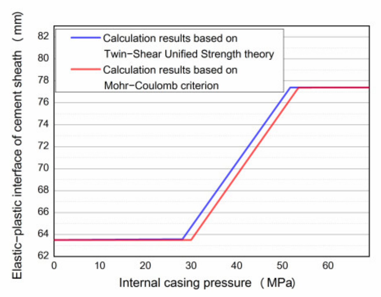
3.1. Influence of Yield Criterion on Elastic–Plastic Change and Micro Annulus of the Cement Sheath

Chu et al. [20] used the Mohr–Coulomb criterion as the yield criterion and analyzed the changes in the micro annulus of the cement sheath based on the test data reported by Jackson et al. [29]. In the experiment conducted by Jackson et al., the cement sheath was maintained between the inner and outer casings, and the gas channeling flow rate of the cement sheath was determined by applying gas channeling pressure on the end of the cement sheath and gradually increasing the internal casing pressure. The objective was to identify the damage to the cement sheath or failure of the interface seal. According to the experimental results, when the internal casing pressure increased to 69 MPa, no gas channeling flow was detected, indicating that the cement sheath was not damaged. However, gas channeling occurred during the pressure drop in the casing, likely owing to the failure of the interface seal caused by the micro annulus.
In this study, the abovementioned working conditions and parameters listed in Table 1 are used to calculate the elastic–plastic and micro annulus changes associated with the cement sheath through the Mohr–Coulomb criterion and twin-shear unified strength theory.

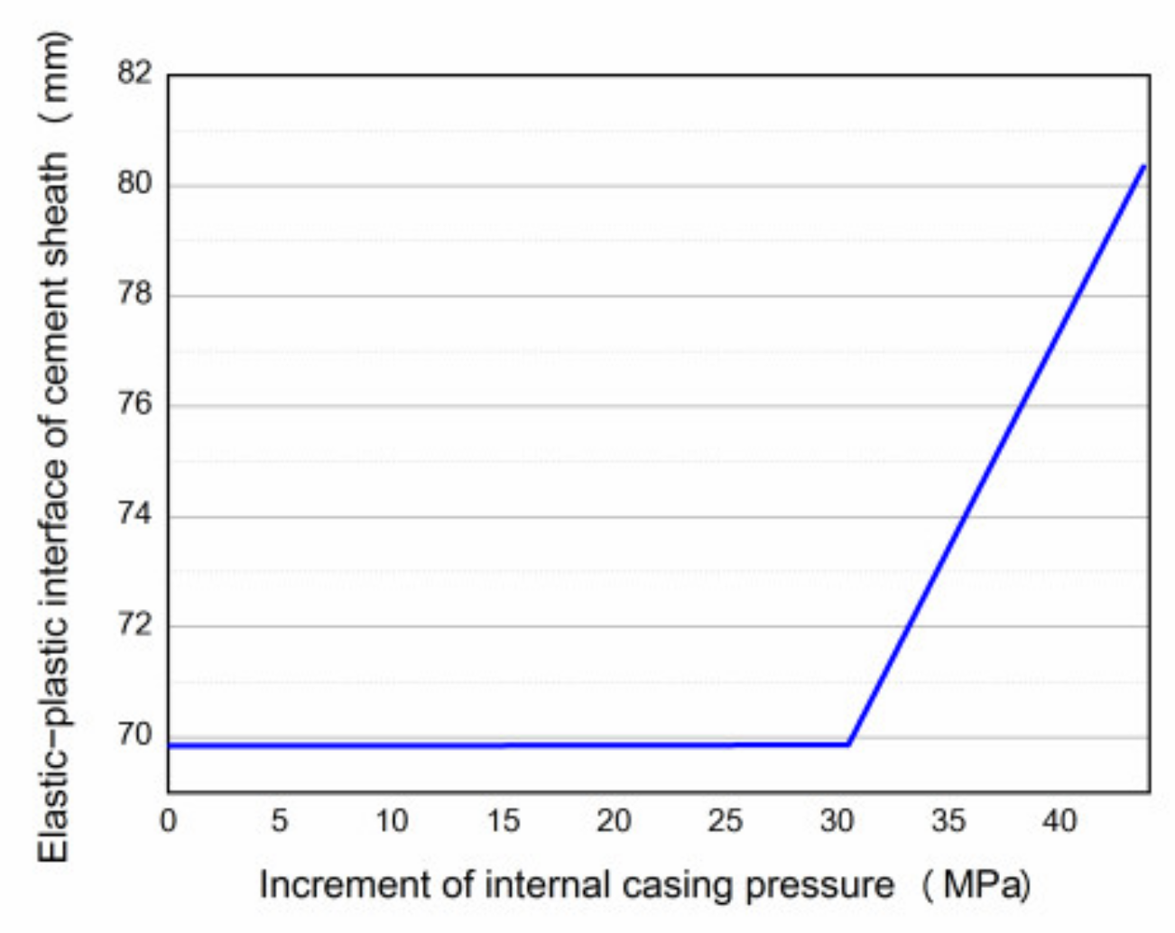
3.1.1. Development of Plastic Zone of the Cement Sheath during Loading

The change in the elastic–plastic boundary of the cement sheath when the internal casing pressure increases from 0 to 69 MPa is calculated, as shown in Figure 4.
The calculation results obtained using the Mohr–Coulomb criterion show that when the internal casing pressure increases to 30 MPa, the inner wall of the cement sheath begins to enter a critical state of plastic yield. The elastic–plastic boundary of the cement sheath gradually expands to the outer wall of the cement sheath, until 53.5 MPa, and the cement sheath enters the plastic state. The calculation results based on the twin-shear unified strength theory demonstrate that the cement sheath enters the critical state of plastic yield when the internal casing pressure is 28.1 MPa, and the cement sheath completely enters the plastic state when the internal casing pressure is 51.7 MPa.
Therefore, the elastic–plastic analysis results of the cement sheath when the Mohr–Coulomb criterion is used as the yield criterion are conservative [30]. This result occurs because the Mohr–Coulomb criterion ignores the influence of the intermediate principal stress [31].

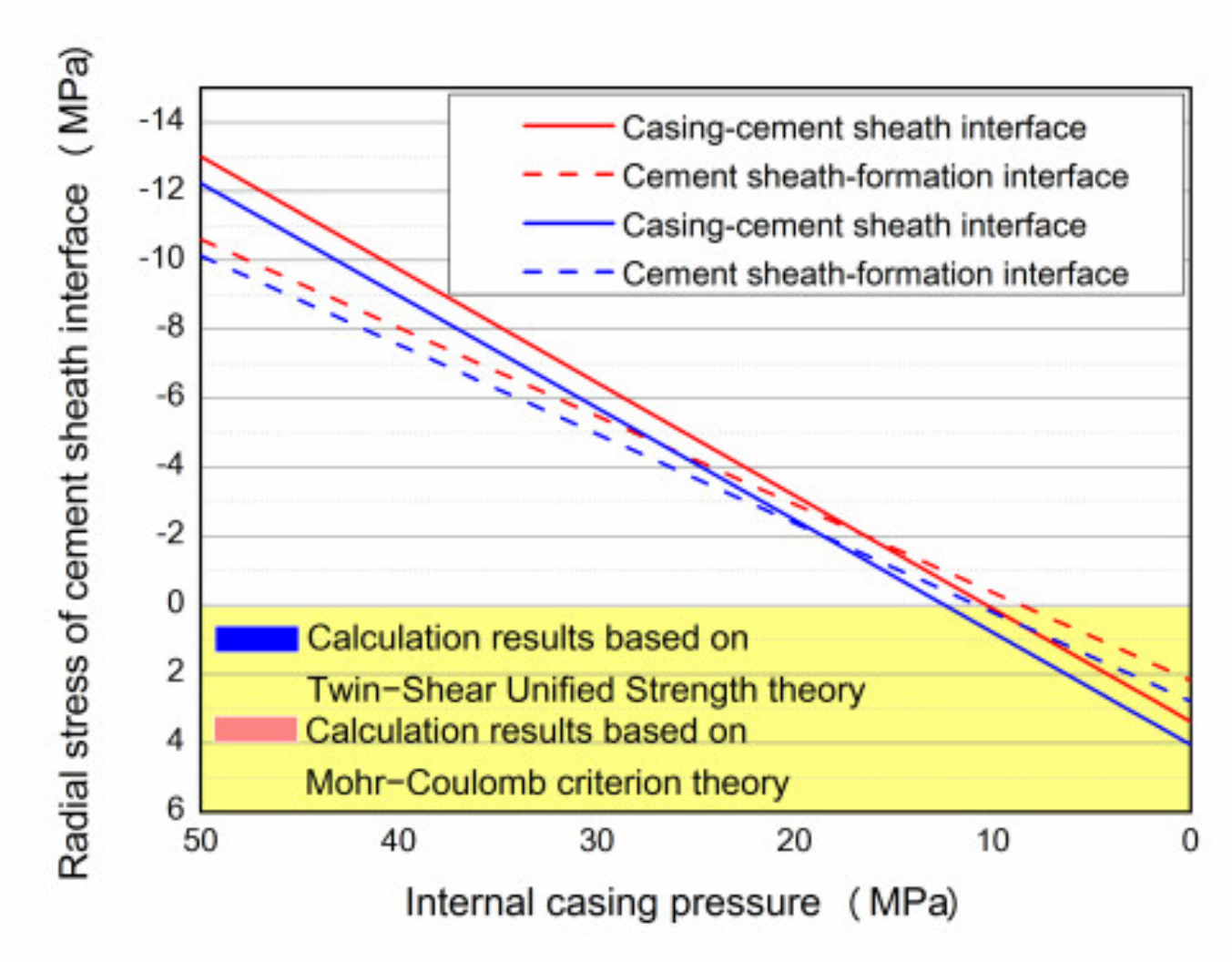
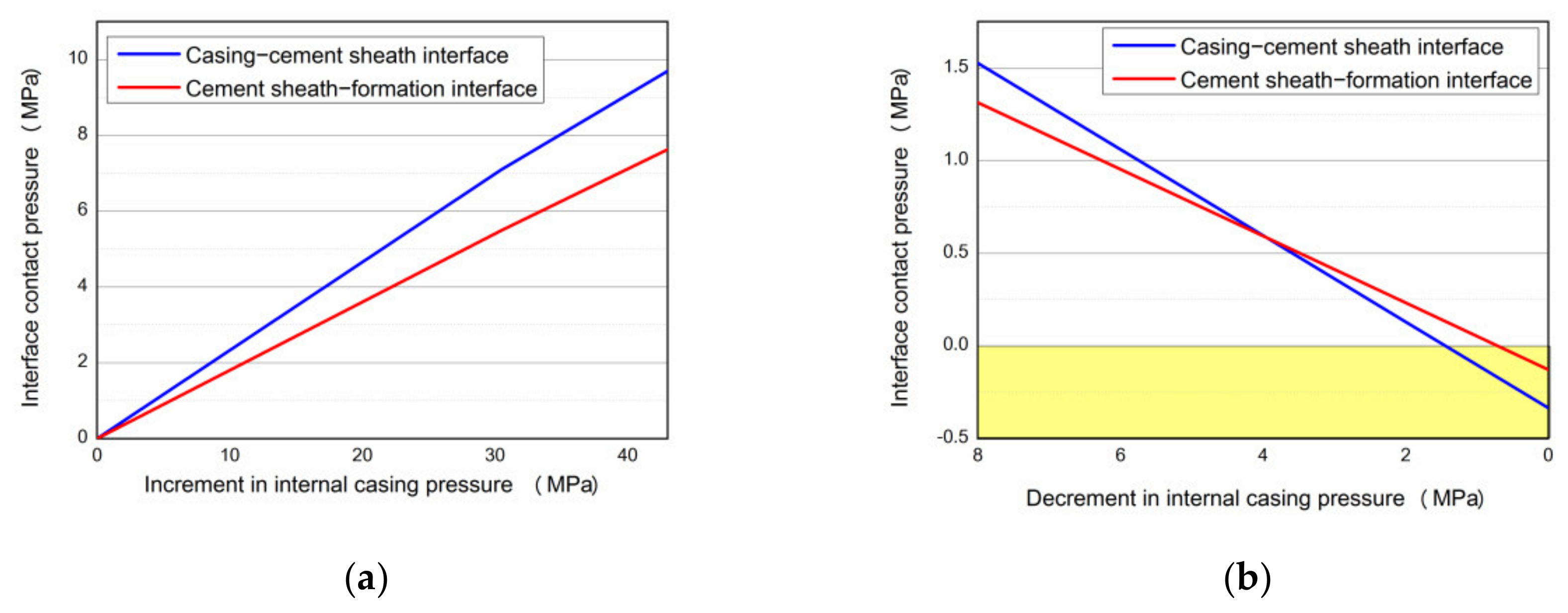
3.1.2. Contact Pressure of the Cement Sheath

As the internal casing pressure increases, the contact pressure changes at the casing-cement sheath interface and cement sheath-formation interface are calculated, as shown in Figure 5. As the pressure increases, the contact pressure of the cement sheath is always positive. Figure 6 shows the interface stress of the cement sheath when the internal casing pressure decreases from 69 MPa to zero. The compressive stress at the casing–cement sheath interface is higher than that at the cement sheath-formation interface in the initial stage of the decrease of the internal casing pressure. As the internal casing pressure decreases, the difference in the interface stress gradually decreases. As the internal casing pressure further decreases, the casing–cement sheath interface exhibits tensile stress until the pressure decreases to zero. The tensile stress at the casing–cement sheath interface is higher than that of the outer wall. Therefore, the casing–cement sheath interface is highly prone to tensile debonding.
The results obtained using the Mohr–Coulomb criterion and twin-shear unified strength theory are compared. In the unloading process, the combined stress calculated using the Mohr–Coulomb criterion is greater than that calculated using the twin-shear unified strength theory. However, the tensile stress obtained by the twin-shear unified strength theory under a low internal casing pressure is larger, indicating that the cement sheath interface calculated using this theory is more prone to bonding failure. Moreover, the results calculated using the Mohr–Coulomb criterion are conservative.

3.1.3. Micro Annulus of the Cement Sheath

When the interface bonding strength is 2 MPa, the micro annulus change at the casing-–cement sheath interface is calculated under the abovementioned conditions, as shown in Figure 7. In the initial stage, when the internal casing pressure decreases, the interface of the casing and cement sheath are not yet debonded, and the displacement of the two entities is the same. As the internal casing pressure further decreases and the casing–cement sheath interface exhibits tensile stress that is greater than the bonding strength, the casing and cement sheath debond. At this time, the inner wall of the cement sheath suddenly retracts and becomes stationary. The casing continues to retract until the internal casing pressure decreases to zero. This phenomenon occurs because the cement sheath expands under tensile stress. When the interface is debonded, the tensile stress of the cement sheath returns to zero, and the cement sheath shrinks. The casing deforms considerably and continues to deform as the internal casing pressure decreases.
In addition, when the twin-shear unified strength theory is used for calculation, the cement sheath generates the micro annulus (0.0174 mm) earlier in the unloading stage, and this micro annulus is larger than that determined using the Mohr–Coulomb criterion (0.0154 mm). The difference between the calculation results and those reported in the literature can be attributed to the different assumptions regarding the interface bonding strength.

3.2. Analysis of Plastic Deformation and Micro Annulus of Cement Sheath in HTHP Wells during Acid Fracturing

The twin-shear unified strength theory considers the influence of the intermediate principal stress, thereby avoiding the conservativeness associated with the Mohr–Coulomb criterion in the elastic–plastic analysis of the cement sheath. Therefore, the twin-shear unified strength theory is considered as the yield criterion, and a gas well in western China is considered as an example for calculation. The elastic–plastic change in the cement sheath and generation of micro annulus under changes in the acid-fracturing temperature and pressure are examined.
The well has a five-segment vertical well structure, and the cement sheath 6745 m deep in the acid-fracturing section is considered as the analysis object. The formation pressure at this depth is 115 MPa, the formation temperature is 168.2 °C, the displacement is 6 m3/min, and the acid-fracturing time is 1 h. The wellbore structure parameters are listed in Table 2.
The composition of the cement slurry: Aksu class G cement + 28% ganister sand (SiO2) + 7% micro-silicon + 1.35% channeling agent (FlOK-2) + 4.5% fluid loss agent (FS-23L) + 3% drag reducer (FS-13L) + 3% retarder (HX-13L) + 0.2% defoaming agent (DF-A) + 4.5% industrial salt + water; the density is 1.95 g/cm3. The physical parameters of the casing, cement sheath, and formation are listed in Table 3.
It should be noted that the parameters in Table 2 and Table 3 are derived from the field engineering design.

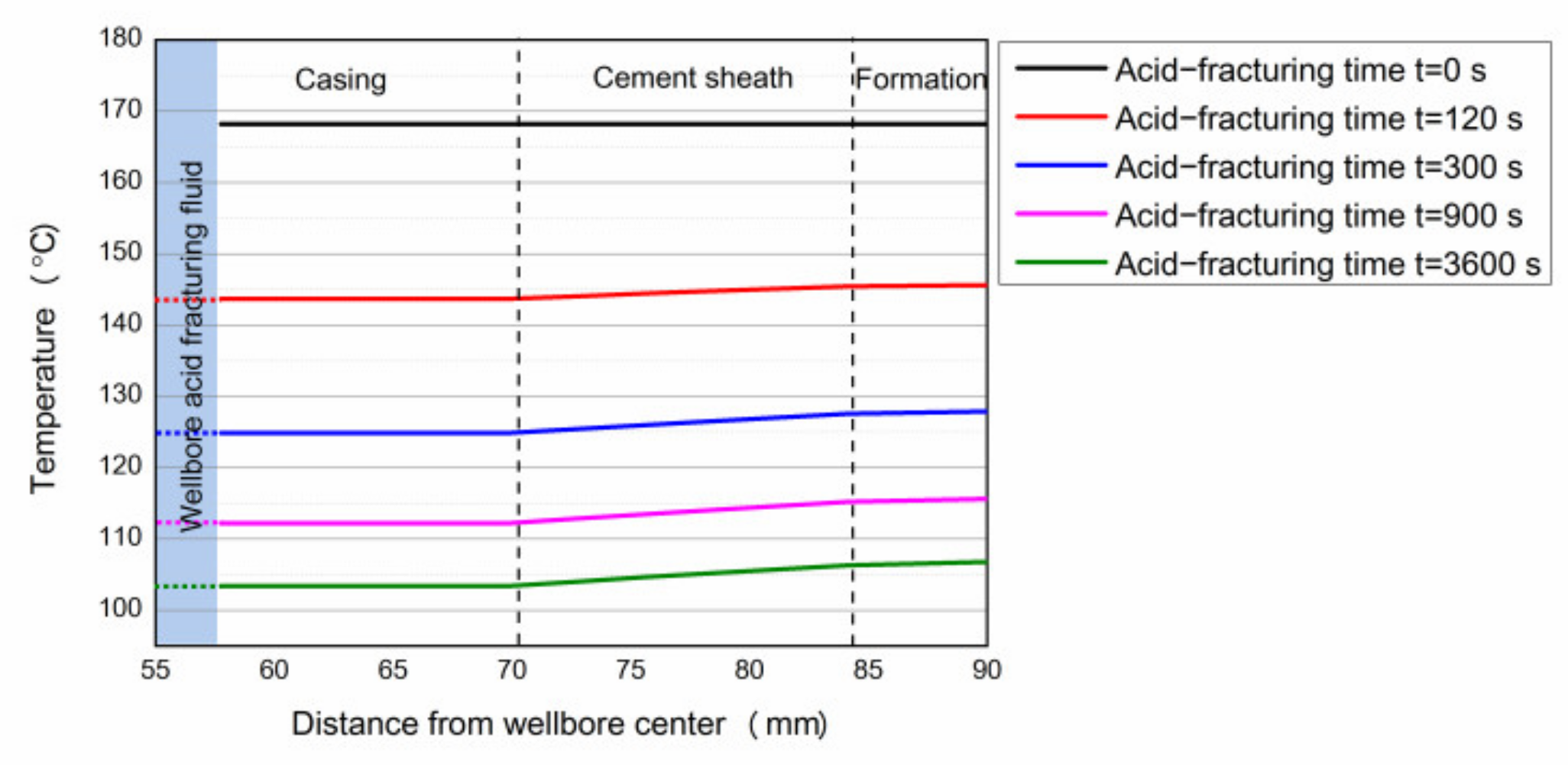
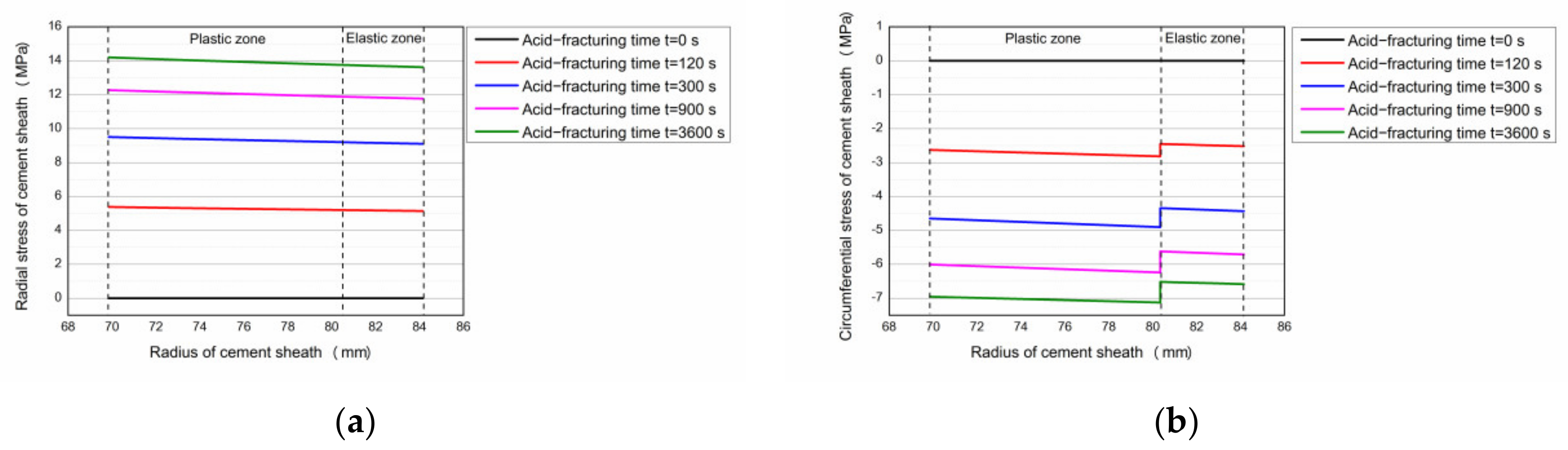
3.2.1. Combined Stress Distribution of the Cement Sheath in the Wellbore

The acid-fracturing fluid density is 1.04 g/cm3, pump pressure is approximately 150 MPa, and friction resistance is approximately 60 MPa. The stress distribution of the cement sheath at the end of the cementing is considered as the initial state, and the elastic–plastic change in the cement sheath during acid fracturing is analyzed, as shown in Figure 8. When the internal casing pressure increases by 30.5 MPa, the cement sheath begins to enter the plastic state. When the internal casing pressure increases to the highest, the radius of the elastic–plastic boundary of the cement sheath is 80.34 mm.
The stresses of the elastic–plastic cement sheath associated with the acid-fracturing load and differential temperature stress are added to determine the combined stress distribution of the cement sheath. Considering the temperature of the wellbore in a static state as the initial condition, the Hasan formula [32,33] is used to calculate the temperature change in the wellbore and temperature distribution of the cement sheath at 6745 m under acid-fracturing conditions. The calculation results are shown in Figure 9. During acid fracturing, the temperature of the wellbore continues to decrease. After 1 h, the wellbore temperature decreases to approximately 64.8 °C, and the temperature of the cement sheath gradually decreased owing to acid fracturing. However, the temperature difference between the inner and outer interfaces of the cement sheath is relatively small (~3 °C).
After determining the temperature distribution of the wellbore, the differential temperature stress of the cement sheath is calculated considering the temperature difference between the casing–cement sheath-formation combination and elastic–plastic state of the cement sheath (Case 2 in Appendix A), as shown in Figure 10. The radial differential temperature stress of the cement sheath corresponds to continuous tensile stress. As the construction time increases, the tensile stress gradually increases. The differential temperature stress in the circumferential direction of the cement sheath is dominated by compressive stress. The circumferential differential temperature stress between the plastic and elastic zones of the cement sheath is discontinuous, and the compressive stress in the plastic zone is greater than that in the elastic zone.
Equation (19) can be used to determine the combined stress distribution of the cement sheath, as shown in Figure 11. The radial combined stress of the cement sheath is continuous, and the circumferential combined stress is discontinuous. In the initial stage of acid fracturing, the cement sheath exhibits compressive combined stress in the radial direction and tensile combined stress in the circumferential direction. At this time, if the tensile combined stress in the circumferential direction of the cement sheath exceeds the tensile strength of the cement sheath, the cement sheath may undergo tensile failure, failing the wellbore seal. As the acid fracturing progresses, the circumferential stress of the cement sheath is affected by the differential temperature stress, which gradually transforms into compressive stress, and the risk of tensile failure of the cement sheath decreases. However, the combined stress in the radial direction of the cement sheath is transformed into tensile stress. When the tensile combined stress at the interface of the cement sheath in the plastic zone is greater than the bonding strength, the interface micro annulus may be generated during acid fracturing.

3.2.2. Micro Annulus of Cement Sheath during Acid Fracturing

The method described in Section 2.4 is used to analyze the influence of the cooling effect on the cement sheath micro annulus during acid fracturing. As can be seen from Figure 8, the cement sheath does not completely enter the plastic state, and thus, although the tensile stress at the outer wall of the cement sheath is higher, the cement sheath-formation interface does not debond.
Analysis of the casing–cement sheath interface indicates that the cement sheath undergoes plastic deformation, and the interface is influenced by the combined effect of the wellbore load and temperature difference, which generates tensile stress. Considering the combined stress at the acid-fracturing time of 3600 s, the casing–cement sheath interface displacement before the interface debonding is calculated, and the results find that the interface displacement is −0.015 mm (the displacement to the center of the wellbore is defined as negative), indicating that the cement sheath “shrinks” in the wellbore under the influence of acid-fracturing load and temperature. Moreover, the tensile combined stress at the interface exceeds the bonding strength, and the risk of debonding at the interface exists.
Continue to calculate the displacement of the casing and cement sheath after debonding, at this time, the contact stress at the casing–cement sheath interface can be considered zero. The calculation results show that owing to the high internal casing pressure, the casing is displaced (0.05 mm) in the direction of the formation. The cement sheath is affected by the formation pressure and differential temperature stress, and its inner wall is displaced (0.002 mm) in the direction of the formation. Because the displacement of the outer wall of the casing is considerably greater than that of the inner wall of the cement sheath, the casing and cement sheath remain in close contact. However, because the stress at the interface satisfies the debonding conditions, the casing–cement sheath interface is considered to debond. Meanwhile, the debonded casing is influenced by the internal pressure and expands, resulting in close contact between the casing and cement sheath.
In addition, the tensile combined stress of the cement sheath-formation interface is higher than that of the casing–cement sheath interface. To analyze whether the cement sheath-formation interface debonds and produces a micro annulus during acid fracturing, we assume that the cement sheath has a lower yield strength and a higher temperature difference between the inner and outer walls. In this scenario, the cement sheath can fully enter the plastic state, which increases the risk of micro annulus generation.
The calculation finds that the displacement of the cement sheath-formation interface before debonding under the assumed conditions is −0.032 mm, indicating that the cement sheath is in a compressed state. Under the effect of the differential temperature stress, the cement sheath-formation interface is subjected to tensile stress, the interface debonds, and a 0.004 mm micro annulus is generated between the outer wall of the cement sheath and formation.
Overall, during acid fracturing, the cement sheath is expected to undergo plastic deformation, and a radial tensile combined stress is expected to be distributed. The tensile stress at the cement sheath-formation interface is greater than that at the casing–cement sheath interface. According to the calculations based on wellbore conditions, although interface debonding occurs at the casing–cement sheath interface, the micro annulus is not generated under the influence of the internal casing pressure. When the cement sheath completely enters the plastic state, interface debonding may occur at the cement sheath-formation interface, and the interface micro annulus may be generated, owing to the temperature difference of the wellbore.

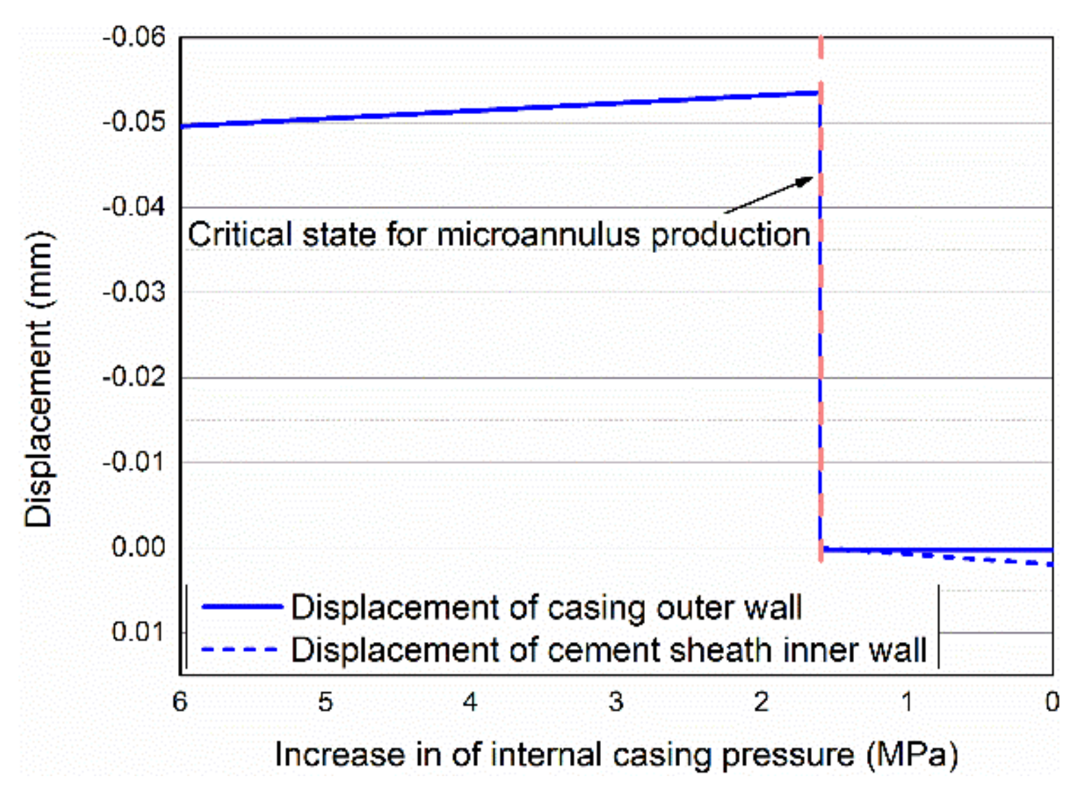
3.2.3. Micro Annulus of Cement Sheath after Acid Fracturing

The method described in Section 2.5 is used to analyze the generation of the cement sheath micro annulus after acid fracturing, based on the original wellbore working conditions. According to existing research, the casing–cement sheath interface undergoes debonding during acid fracturing; however, because of the internal casing pressure, the casing and cement sheath remain in close contact. As described in this section, the micro-annulus size of the cement sheath interface can be obtained by calculating the internal casing pressure under the condition of interface debonding, and the displacement of the outer wall of the casing is less than that of the inner wall of the cement sheath. In the calculation, it is considered that the rate of decrease in the internal casing pressure is considerably greater than the rate of increase in the wellbore temperature. Therefore, the influence of wellbore temperature changes on the differential temperature stress is ignored (the differential temperature stress remains constant).
Figure 12 shows the displacement of the casing–cement sheath interface and changes in the size of the micro annulus after acid fracturing. The casing–cement sheath interface first shrinks into the wellbore as the internal casing pressure decreases. Next, when the displacement of the outer wall of the casing is equal to that of the inner wall, the casing-cement sheath interface enters a critical state in which the micro annulus is generated. As the internal casing pressure decreases, the displacement of the outer wall of the casing returns to the initial state, and the contact pressure between the casing and the cement sheath is zero. However, the cement sheath-formation combination is influenced by the differential temperature stress and produces displacement along the direction of the wellbore with the formation of a micro annulus sized 0.00196 mm.
To compare the influence of the differential temperature stress on the cement sheath micro annulus, the cement sheath interfaces contact pressure during acid fracturing was calculated based on the same wellbore working conditions while ignoring the differential temperature stress. As shown in Figure 13, when the differential temperature stress is ignored, the contact pressure of the cement sheath interface during acid fracturing corresponds to compressive stress. After the acid fracturing, when the internal casing pressure decreases, the contact pressure of the cement sheath interface transformed to tensile stress that is less than the interface bonding strength. Therefore, the cement sheath interface will not debond.
Therefore, in the analysis of the cement sheath interface debonding and micro annulus formation, it is necessary to consider the effect of the differential temperature stress; otherwise, the analysis results would be conservative, and the risk associated with the interface debonding and micro annulus formation may not be captured.

4. Discussion

In this study, the micro annulus caused by the wellbore cooling effect was analyzed; the study found that the debonding of the cement sheath interface will occur due to the differential temperature stress during acid-fracturing. Meanwhile, after acid fracturing, the cement sheath will also be affected by the comprehensive stress, and there was a risk of micro annulus formation. Among them, it should be noted that, under the wellbore parameters and conditions in the study, it was found that the elastic–plastic cement sheath will only cause interface debonding, but will not generate micro annulus in the acid fracturing stage. This did not mean that there was no risk of cement sheath interface sealing failure in the actual wellbore acid-fracturing process. The reason was that the debonded cement sheath interface may break into the acid fracturing fluid, causing cracks (or micro annulus) to propagate along the interface. The fluid load applied to the debonding interface of the cement sheath was ignored in our study and this is an aspect that remains to be studied.

5. Conclusions

To address the interface debonding problem of the cement sheath of high-temperature and high-pressure wells under acid fracturing, the cement sheath yield and micro annulus are examined. The plastic deformation of the cement sheath from the beginning to the end of acid fracturing and the mechanism of micro annulus generation are analyzed. The influence of the physical parameters of the cement sheath is discussed, and the following conclusions are derived:
(1) The elastic–plastic mechanical model of cement sheath is established based on the twin-shear unified strength theory. According to the comparative analysis of the theoretical and experimental results reported by Chu et al. and Jackson et al., the proposed model can consider the influence of the intermediate principal stress on the yield state of the cement sheath, and avoid the conservativeness of the plastic analysis results of the cement sheath based on the Mohr-Coulomb criterion.
(2) Considering the wellbore load and temperature difference during acid fracturing, calculation models of the combined stress of the casing–cement sheath-formation combination and interface micro annulus during and after acid fracturing are established. The models are used to determine the combined stress and displacement of the cement sheath from the beginning to the end of acid fracturing. The mechanism and development law of the micro annulus between the casing–cement sheath interface and cement sheath-formation interface are analyzed.
(3) During acid fracturing, if the cement sheath is not fully yielded, the casing–cement sheath interface is influenced by the differential temperature stress, and the interface debonds. However, under the influence of the internal casing pressure, the casing–cement sheath interface remains in close contact, and no micro annulus is generated. If the cement sheath completely enters the plastic state, the cement sheath-formation interface is more susceptible to differential temperature stress, and interface debonding and micro annulus occurs.
(4) After acid fracturing, the micro annulus is more likely to be formed at the casing-cement sheath interface, owing to the decrease in the internal casing pressure. In this stage, the influence of the temperature difference of the cement sheath must be considered; otherwise, the analysis results would be conservative, and the risks associated with interface debonding and micro annulus formation may not be captured.

Author Contributions

Methodology, modeling and validation: D.S., X.W. and S.H.; investigation: J.L. and G.Z.; formal analysis: D.S. and J.S.; resources, supervision: Z.L.; writing—original draft preparation: D.S.; writing—review and editing: X.W. All authors have read and agreed to the published version of the manuscript.

Funding

The authors gratefully acknowledge the financial support provided by the Science and Technology Cooperation Project of the CNPC-SWPU Innovation Alliance (No. 2020CX040000); the National Natural Science Foundation of China (No. 52004231); Sichuan Science and Technology Program (No. 2020JDTD0019).

Institutional Review Board Statement

Not applicable.

Informed Consent Statement

Not applicable.

Data Availability Statement

The data that support the findings of this study are available from the corresponding author upon reasonable request.

Conflicts of Interest

The authors declare no conflict of interest.

Appendix A. Differential Temperature Stress Model of Casing-–Cement Sheath-Format during Acid Fracturing

The differential temperature stress and displacement equations of the thick-walled cylinder can be expressed as [28]:
σ r t = E α 1 v r 2 R i r t r d r + C 3 C 4 r 2 σ θ t = E α 1 v r 2 R i r t r d r + C 3 + C 4 r 2 σ z t = E α t 1 v + 2 v C 3 ,
u t = 1 + v 1 v α r R i r t r d r + C 1 r + C 2 r ,
where α denotes the coefficient of linear expansion (1/°C), t represents the temperature difference (°C), and σtr, σtθ, and σtz represent the radial, circumferential, and axial stresses caused by the temperature difference (MPa), respectively. E represents the Young’s modulus (MPa). v represents the Poisson’s ratio. r represents radius of any point in the thick-walled cylinder (mm). Ri represents the inner wall radius of the thick-walled cylinder (mm). Furthermore, ut denotes the displacement caused by the differential temperature stress (mm) and C1, C2, C3, and C4 are defined as
C 3 = E C 1 ( 1 + ν ) ( 1 2 ν )   ;   C 4 = E C 2 1 + ν .
Case 1: The cement sheath is in the elastic state
The differential temperature stress for the casing, cement sheath, and formation is described in Appendix B of the existing study [34].
Case 2: The cement sheath is in the elastic–plastic state
In this state, based on the boundary conditions and continuity conditions in Case 1, we re-assume that the casing–elastic cement sheath-formation combination is the casing-plastic cement sheath–elastic cement sheath-formation combination. The interface of the plastic and elastic cement sheath satisfies the continuous radial stress and displacement, as shown in Equation (A4):
σ r c p t r = r p = σ r c e t r = r p   ;   u c p t r = r p = u c e t r = r p ,
where σtrcp|r = rp and σtrce|r = rp denote the radial differential temperature stress of elastic and plastic cement sheaths at the elastic-–plastic interface (MPa), respectively. utcp|r = rp and utce|r = rp denote the displacement of the elastic and plastic cement sheaths at the elastic–plastic interface, caused by the temperature difference (mm), respectively.
The differential temperature stress can be solved by the following equations:
E s α s ( 1 v s ) r 1 2 r i r 1 t r d r + E s C 1 1 + v s 1 2 v s E s C 2 1 + v s r 1 2 E c p C 1 cp 1 + v c p 1 2 v c p + E c p C 2 cp 1 + v c p r 1 2 = 0 E c p α c p ( 1 v c p ) r p 2 r 1 r p t r d r + E c p C 1 cp 1 + v c p 1 2 v c p E c p C 2 cp 1 + v c p r p 2 E c e C 1 ce 1 + v c e 1 2 v c e + E c e C 2 ce 1 + v c e r p 2 = 0 E c e α c e ( 1 v c e ) r 2 2 r p r 2 t r d r + E c e C 1 ce 1 + v c e 1 2 v c e E c e C 2 ce 1 + v c e r 2 2 E f C 1 1 + v f 1 2 v f + E f C 2 1 + v f r 2 2 = 0 E s C 1 1 + v s 1 2 v s E s C 2 1 + v s r i 2 = 0 E f α f ( 1 v f ) r o 2 r 2 r o t r d r + C 3 E f C 1 1 + v f 1 2 v f E f C 2 1 + v f r o 2 = 0 1 + v s 1 v s α s r 1 r i r 1 t r d r + C 1 r 1 + C 2 r 1 C 1 cp r 1 C 2 cp r 1 = 0 1 + v c p 1 v c p α c p r p r 1 r p t r d r + C 1 cp r p + C 2 cp r p C 1 ce r p C 2 ce r p = 0 1 + v c e 1 v c e α c e r 2 r p r 2 t r d r + C 1 ce r 2 + C 2 ce r 2 C 1 r 2 C 2 r 2 = 0
where Ecp and Ece denote Young’s modulus of the cement sheath in the plastic and elastic zones (MPa), respectively; vcp and vce denote Poisson’s ratio of the cement sheath in plastic and elastic zones, respectively; αs, αf, αcp, and αce denote thermal expansivity of the casing, the formation, and the cement sheath in plastic and elastic zones (1/°C); C1cp’, C2cp’, C1ce’, and C2ce’ are the intermediate parameters.
In this study, it is considered that Young’s modulus and Poisson’s ratio of the cement sheath in the plastic zone are the same as those in the elastic zone.
Case 3: The cement sheath is in the plastic state
The method for solving the differential temperature stress and displacement of the casing-–cement sheath-formation combination is the same as that in Case 1. The difference is that the sizes and mechanical parameters of the plastic cement sheath must be appropriately substituted for calculations.

Appendix B. Displacement and Contact Pressure of Cement Sheath Associated with Wellbore Unloading

In the wellbore unloading stage, the micro annulus of the cement sheath can be obtained by calculating the difference between the casing–cement sheath interface displacement (or cement sheath-formation interface) after debonding, specifically [20]:
The radial displacement at the outer wall of the casing can be characterized by the following equation:
u s o n P = ( 2 v s ) r i 2 r 1 E s ( r 1 2 r i 2 ) p i n ( 1 2 v s ) r 1 3 + ( 1 + v s ) r i 2 r 1 E s ( r 1 2 r i 2 ) p 1 n P ,
where u s o n P represents the displacement of the outer wall of the casing caused by the internal casing pressure (mm). p i n represents the internal casing pressure during unloading (MPa). p 1 n P represents the contact pressure at the casing-–cement sheath interface during unloading (MPa).
which can be rewritten as
u s o n P = f 1 p i n f 2 p 1 n P .
Similarly, the radial displacement of the inner wall of the formation is:
u f i n P = ( 1 2 v f ) r 2 3 + ( 1 + v f ) r 2 r o 2 E f ( r o 2 r 2 2 ) p 2 n p ( 2 v f ) r 2 r o 2 E f ( r o 2 r 2 2 ) p o ,
where u f i n P represents the displacement of the inner wall of the formation (mm). p 2 n P represents the contact pressure at the cement sheath-formation interface during unloading (MPa).
which can be rewritten as
u f i n p = f 7 p 2 n p f 8 p o .
In the unloading stage, the radial displacement of the cement sheath inner wall is the sum of the displacement of the cement sheath inner wall during loading and radial displacement of the inner wall when the internal casing pressure decrease. The corresponding equations are
u c i n p = u c p i m p + u c i r p
u c i n p = u c p i m p + ( 1 2 v c ) r 1 3 + ( 1 + v ) r 1 r 2 2 E c ( r 2 2 r 1 2 ) ( p 1 n p p 1 m p ) ( 2 v c ) r 1 r 2 2 E c ( r 2 2 r 1 2 ) ( p 2 n p p 2 m p ) ,
where u c i n P , u c p i m P , and u c i r P denoted the radial displacements of the inner wall of the cement sheath during unloading and loading and when the internal casing pressure decreased (mm), respectively.
The following expression can be obtained:
u c i n p = u c p i m p + f 3 ( p 1 n p p 1 m p ) f 4 ( p 2 n p p 2 m p ) .
Similarly, the radial displacement of the outer wall of the cement sheath during unloading can be expressed as
u c o n p = u c e o m p + ( 2 v c ) r 1 2 r 2 E c ( r 2 2 r 1 2 ) ( p 1 n p p 1 m p ) ( 1 2 v c ) r 2 3 + ( 1 v c ) r 1 2 r 2 E c ( r 2 2 r 1 2 ) ( p 2 n p p 2 m p ) ,
where u c o n P and u c e o m P denote the radial displacements of the outer wall of the cement sheath during unloading and loading (mm), respectively.
The following expression can be obtained:
u c o n p = u c e o m p + f 5 ( p 1 n p p 1 m p ) f 6 ( p 2 n p p 2 m p ) .
It is assumed that in the unloading process, the inner wall of the casing and cement sheath have adequate bonding strength to prevent the interface from being debonded. In this case, the casing–cement sheath-formation combination satisfies the continuity condition of radial displacement:
u s o n p = u c i n p u c o n p = u f i n p .
By substituting Equations (A11), (A12), (A13), and (A14) into Equation (A15), the contact pressure of the inner and outer walls of the cement sheath before the interface bonding can be calculated:
p 1 n p = f 1 ( f 6 + f 7 ) p i n + f 4 f 8 p o ( f 6 + f 7 ) u c p i + f 4 u c e o ( f 2 + f 3 ) ( f 6 + f 7 ) f 4 f 5 ,
p 2 n p = f 1 f 5 p i n + f 8 ( f 2 + f 3 ) p o f 5 u c p i + ( f 2 + f 3 ) u c e o ( f 2 + f 3 ) ( f 6 + f 7 ) f 4 f 5 ,
where
u c p i = u c p i m p f 3 p 1 m p + f 4 p 2 m p u c e o = u c e o m p f 5 p 1 m p + f 6 p 2 m p
For example, in the case of the casing–cement sheath interface, the casing after the interface debonding bears only the internal casing pressure, and the radial displacement of the casing outer wall is
u s o n p = ( 2 v s ) r i 2 r o E s ( r 1 2 r i 2 ) p i n .
After the interface is debonded, the contact pressure of the inner wall of the cement sheath is zero. The radial displacement of the inner wall of the cement sheath during unloading can be expressed as follows:
u c i n p = u c p i m p + ( 1 2 v c ) r 1 3 + ( 1 v c ) r 1 r 2 2 E c ( r 2 2 r 1 2 ) ( p 1 m p ) ( 2 v c ) r 1 r 2 2 E c ( r 2 2 r 1 2 ) ( p 2 n p p 2 m p ) .

References

  1. Zhang, C.; Cai, J.; Xu, H.; Cheng, X.; Guo, X. Mechanical properties and mechanism of wollastonite fibers reinforced oil well cement. Constr. Build. Mater. 2020, 260, 120461. [Google Scholar] [CrossRef]
  2. Cheng, X.; Chen, Z.; Gu, T.; Zeng, L.; Yao, L.; Chen, Z.; Huang, K.; Zhang, Z.; Zhang, C.; Liu, K.; et al. Study on the dynamic and static mechanical properties of microsphere rubber powder reinforced oil well cement composites. Constr. Build. Mater. 2021, 309, 125145. [Google Scholar] [CrossRef]
  3. Zhang, C.; Li, Y.; Cheng, X.; Liang, S.; Guo, X.; Zhao, H.; Song, Y. Effects of plasma-treated rock asphalt on the mechanical properties and microstructure of oil-well cement. Constr. Build. Mater. 2018, 186, 163–173. [Google Scholar] [CrossRef]
  4. Xiang, H.; Han, G.; Ma, G.; Zhu, Z.; Zhu, L.; Peng, L. Pressure Transient Analysis and Transient Inflow Performance Relationship of Multiple-Fractured Horizontal Wells in Naturally Fractured Reservoirs by a Trilinear Flow Model. ACS Omega 2021, 6, 19222–19232. [Google Scholar] [CrossRef] [PubMed]
  5. Xu, H.; Ma, T.; Peng, N.; Yang, B. Influences of fracturing fluid injection on mechanical integrity of cement sheath under four failure modes. Energies 2018, 11, 3534. [Google Scholar] [CrossRef] [Green Version]
  6. Zhang, X.; Bi, Z.; Wang, L.; Guo, Y.; Yang, C.; Yang, G. Shakedown analysis on the integrity of cement sheath under deep and large-scale multi-section hydraulic fracturing. J. Pet. Sci. Eng. 2022, 208, 109619. [Google Scholar] [CrossRef]
  7. Chen, Y.; Peng, X.; Yu, H. Mechanical performance experiments on rock and cement, casing residual stress evaluation in the thermal recovery well based on thermal-structure coupling. Energy Explor. Exploit. 2017, 35, 591–608. [Google Scholar] [CrossRef]
  8. Guo, H.; Wang, G.; Wang, Z. New Practices for Cement Integrity Evaluation in the Complex Environment of Xinjiang Oil Field. In Proceedings of the SPE Asia Pacific Oil and Gas Conference and Exhibition, Perth, Australia, 22–24 October 2012; Society of Petroleum Engineers: Richardson, TX, USA, 2012. [Google Scholar]
  9. Liu, H.; Cao, L.; Xie, J.; Yang, X.; Zeng, N.; Zhang, X.; Chen, F. Research and practice of full life cycle well integrity in HTHP well. In Proceedings of the Tarim Oilfield, International Petroleum Technology Conference, Beijing, China, 26–28 March 2019; Society of Petroleum Engineers: Richardson, TX, USA, 2019. [Google Scholar]
  10. Davies, R.J.; Almond, S.; Ward, R.S.; Jackson, R.B.; Adams, C.; Worrall, F.; Herringshaw, L.G.; Gluyas, J.G.; Whitehead, M.A. Oil and gas wells and their integrity: Implications for shale and unconventional resource exploitation. Mar. Pet. Geol. 2014, 56, 239–254. [Google Scholar] [CrossRef] [Green Version]
  11. Guo, Y.; Li, X.; Feng, S.; Zhang, C.; Liu, R.; Zhang, Z.; Li, T.; Guo, P.; Wang, R.; Taoutaou, S.; et al. Cementing practices to solve well integrity challenges of ultra deep high temperature wells in western China. In Proceedings of the Abu Dhabi International Petroleum Exhibition & Conference, Abu Dhabi, United Arab Emirates, 7–10 November 2016; Society of Petroleum Engineers: Richardson, TX, USA, 2016. [Google Scholar]
  12. Oyarhossein, M.; Dusseault, M.B. Wellbore Stress Changes and Microannulus Development Because of Cement Shrinkage. In Proceedings of the 49th US Rock Mechanics/Geomechanics Symposium, San Francisco, CA, USA, 29 June–1 July 2015; American Rock Mechanics Association: Alexandria, VA, USA, 2015. [Google Scholar]
  13. Goodwin K., J.; Crook R., J. Cement Sheath Stress Failure. In Proceedings of the SPE Annual Technical Conference and Exhibition, New Orleans, USA, 23–26 September 1993; Society of Petroleum Engineers: Richardson, TX, USA, 1993. [Google Scholar]
  14. Albawi, A.; De Andrade, J. Experimental set-up for testing cement sheath integrity in Arctic wells. In Proceedings of the Offshore Technology Conference, Houston, TX, USA, 5–8 May 2014. [Google Scholar]
  15. De Andrade, J.; Torsaeter, M.; Todorovic, J.; Opedal, N.; Stroisz, A.; Vrålstad, T. Influence of casing centralization on cement sheath integrity during thermal cycling. In Proceedings of the IADC/SPE Drilling Conference and Exhibition, Fort Worth, TX, USA, 4 March 2014; Society of Petroleum Engineers: Richardson, TX, USA, 2014; p. 10. [Google Scholar]
  16. Shadravan, A.; Schuber, J.; Amani, M.; Teodori, C. HPHT cement sheath integrity evaluation method for unconventional wells. In Proceedings of the SPE International Conference on Health, Safety, and Environment, Long Beach, CA, USA, 17–19 March 2014. [Google Scholar]
  17. Zeng, Y.; Liu, R.; Li, X.; Zhou, S.; Tao, Q.; Lu, P. Cement sheath sealing integrity evaluation under cyclic loading using large-scale sealing evaluation equipment for complex subsurface settings. J. Pet. Sci. Eng. 2019, 176, 811–820. [Google Scholar] [CrossRef]
  18. Li, Z.; Zhang, K.; Guo, X.; Liu, J.; Cheng, X.; Du, J. Study of the failure mechanisms of a cement sheath based on an equivalent physical experiment. J. Nat. Gas Sci. Eng. 2016, 31, 331–339. [Google Scholar] [CrossRef]
  19. Mueller, D.T.; GoBoncan, V.; Dillenbeck, R.L.; Heinold, T. characterizing casing-cement-formation interactions under stress conditions: Impact on long-term zonal isolation. In Proceedings of the SPE Annual Technical Conference and Exhibition, Houston, TX, USA, 26–29 September 2004. [Google Scholar]
  20. Chu, W.; Shen, J.; Yang, Y.; Li, Y.; Gao, D. Calculation of micro-annulus size in casing-cement sheath-formation system under continuous internal casing pressure change. Pet. Explor. Dev. 2015, 42, 414–421. [Google Scholar] [CrossRef]
  21. Dusseault, M.B.; Gray, M.N.; Nawrocki, P.A. Why oilwells leak: Cement behavior and long-term consequences. In Proceedings of the SPE International Oil and Gas Conference and Exhibition, Beijing, China, 7–10 November 2000; Society of Petroleum Engineers: Richardson, TX, USA, 2000. [Google Scholar]
  22. Taleghani, A.D.; Klimenko, D. An Analytical Solution for Microannulus Cracks Developed Around a Wellbore. J. Energy Resour. Technol. 2015, 137, 062901. [Google Scholar] [CrossRef]
  23. Zhang, H.; Shen, R.; Yuan, G.; Ba, Z.; Hu, Y. Cement sheath integrity analysis of underground gas storage well based on elastoplastic theory. J. Petrol. Sci. Eng. 2017, 159, 818–829. [Google Scholar] [CrossRef]
  24. Chen, Z.; Dai, C.; Liao, M. Analyses of Mechanical Conditions and Affecting Factors for Forming Micro-Annuli in a Casing-Cement-Formation System. In Proceedings of the 52nd U.S. Rock Mechanics/Geomechanics Symposium, Seattle, WA, USA, 17–20 June 2018; American Rock Mechanics Association: Alexandria, VA, USA, 2018. [Google Scholar]
  25. Zhao, C.; Li, J.; Liu, G.; Zhang, X. Analysis of the influence of cement sheath failure on sustained casing pressure in shale gas wells. J. Nat. Gas Sci. Eng. 2019, 66, 244–254. [Google Scholar] [CrossRef]
  26. Yu, M.-H.; Kolupaev, V.; Li, Y.-M.; Li, J.-C. Advances in Unified Strength Theory and its Generalization. Procedia Eng. 2011, 10, 2508–2513. [Google Scholar] [CrossRef] [Green Version]
  27. Amenzade, Y.A. Theory of Elasticity; Mir Publishers: Moscow, Russia, 1979. [Google Scholar]
  28. Boles, M.A. Thermodynamics: An Engineering Approach; McGraw-Hill Higher Education: New York, USA, 2008. [Google Scholar]
  29. Jackson, P.B.; Murphey, C.E. Effect of casing pressure on gas flow through a sheath of set cement. In Proceedings of the SPE/IADC Drilling Conference, Amsterdam, The Netherlands, 22 February 1993; Society of Petroleum Engineers: Richardson, TX, USA, 1993. [Google Scholar]
  30. Huang, J.; Zhao, M.; Du, X.; Dai, F.; Ma, C.; Liu, J. An Elasto-Plastic Damage Model for Rocks Based on a New Nonlinear Strength Criterion. Rock Mech. Rock Eng. 2018, 51, 1413–1429. [Google Scholar] [CrossRef]
  31. Chen, S.; Bao, W.; Jin, S. Twin τ2 Strength Theory and Its Application to Concrete Material. J. Univ. Hydraul. Electr. Eng./Yichang 2003, 25, 504–506. [Google Scholar]
  32. Hasan, A.R.; Kabir, C.S.; Wang, X. A Robust Steady-State Model for Flowing-Fluid Temperature in Complex Wells. SPE Prod. Oper. 2009, 24, 269–276. [Google Scholar] [CrossRef]
  33. Hasan, A.R.; Kabir, C.S.; Wang, X. Wellbore Two-Phase Flow and Heat Transfer During Transient Testing. SPE J. 1998, 3, 174–180. [Google Scholar] [CrossRef]
  34. Su, D.; Li, Z.; Huang, S.; Wu, X.; Li, J.; Xue, Y. Experiment and failure mechanism of cement sheath integrity under development and production conditions based on a mechanical equivalent theory. Energy Sci. Eng. 2021, 9, 2400–2422. [Google Scholar] [CrossRef]
Figure 1. Schematic diagram of acid-fracturing and the change rule of the temperature and pressure during acid-fracturing.
Processes 10 00966 g001
Figure 2. Schematic of casing–elastoplastic cement sheath-formation combination.
Processes 10 00966 g002
Figure 3. Schematic diagram of the micro annulus generation.
Processes 10 00966 g003
Figure 4. Development of elastic–plastic boundary of cement sheath under different yield criteria.
Processes 10 00966 g004
Figure 5. Change in the contact pressure at the cement sheath interface during loading.
Processes 10 00966 g005
Figure 6. Interface stress change in the cement sheath during unloading.
Processes 10 00966 g006
Figure 7. Change in the cement sheath micro annulus in the unloading stage.
Processes 10 00966 g007
Figure 8. Elastic–plastic interface of the cement sheath during acid fracturing.
Processes 10 00966 g008
Figure 9. Wellbore temperature and temperature distribution of the cement sheath.
Processes 10 00966 g009
Figure 10. Differential temperature stress of cement sheath during acid fracturing. (a) Radial differential stress; (b) Circumferential differential stress.
Processes 10 00966 g010
Figure 11. Combined stress of cement sheath during acid fracturing. (a) Radial combined stress; (b) Circumferential combined stress.
Processes 10 00966 g011
Figure 12. Displacement and micro annulus of casing–cement sheath interface.
Processes 10 00966 g012
Figure 13. Contact pressure of wellbore cement sheath interface determined without considering the differential temperature stress. (a) Acid fracturing stage; (b) End of acid fracturing (unloading stage).
Processes 10 00966 g013
Table 1. Parameters in Jackson et al.’s experiment and Chu et al.’s theoretical calculation [20,29].
Inner radius of inner casing (mm)54.3Outer radius of inner casing (mm)63.5
Inner radius of outer casing (mm)77.39Outer radius of outer casing (mm)88.9
Casing internal pressure (MPa)69Casing external pressure (MPa)0
Young’s modulus of casing (GPa)210Poisson’s ratio of casing0.3
Young’s modulus of cement sheath (GPa)13.8Poisson’s ratio of cement sheath0.25
Internal friction angle of cement sheath (°)30Cement sheath cohesion (MPa)5.77
Table 2. Wellbore structure parameters of the high-pressure gas well.
SegmentDrill Size (mm)Casing Size (mm)Casing Thickness (mm)Casing Shoe Position (m)Cement Slurry Back to High (m)
1660.450812.702000
2444.5365.1313.8843400
3333.4273.0513.8464660
4241.3201.715.1262506700
5168.3139.712.0970406700
Table 3. Physical parameters of the casing, cement sheath, and formation.
ParametersValueParametersValue
Thermal expansion coefficient of casing1.3 × 10−5 1/°CThermal expansion coefficient of cement sheath1.5 × 10−5 1/°C
Thermal expansion coefficient of formation7 × 10−5 1/°CYoung’s modulus of casing210,000 MPa
Poisson’s ratio of casing0.3Young’s modulus of cement sheath13,800 MPa
Poisson’s ratio of cement sheath0.25Young’s modulus of formation29,500 MPa
Poisson’s ratio of formation0.33Cement sheath bond strength4 MPa
Publisher’s Note: MDPI stays neutral with regard to jurisdictional claims in published maps and institutional affiliations.

