1. Introduction
The main systems for generating electricity in the leading economically-developed countries are large-block electric and thermal power plants. Despite the obvious advantages of centralized electricity generation, such as good economic indicators, this system has a number of significant disadvantages:
- -
the distance from consumers makes it necessary to bear large energy losses in the transmission networks;
- -
the failure of a large generation source leads to a critical situation for all consumers of the centralized network. The accidents at the Chernobyl nuclear power plant, the Sayano–Shushenskaya hydro power plant, and the Fukushima nuclear power plant have confirmed this factor in practice.
One of the ways to improve the efficiency and reliability of power supply is the development of distributed generation. Distributed energy is the production of electric and thermal energy by a multitude of small, networked generating devices connected to a central power supply network or operating independently. A distributed power system is similar to the internet, where the failure of one or more sources does not lead to a significant disruption of the operability of the entire network.
Small- and medium-power distributed generation power plants based on high-speed gas turbines are widely used in Russia and abroad. The main foreign manufacturers are: Bowman Power Systems (Southampton, UK, 25, 35, 80, 100 kW), Capstone Turbine Corporation (Van Nuys, CA, USA, 30 kW, 65 kW, 200 kW, 600 kW, 800 kW, 1 MW), Calnetix Power Solutions (Cerritos, CA, USA, 100 kW), Honeywell Power Systems (Charlotte, NC, USA, 75 kW), Ingersoll Rand Energy Systems (Dublin, Ireland, 70 and 250 kW), Toyota (Tokyo, Japan, 30, 50, 300, 375 kW), and Turbec S. p.A. (Via F Lli Bandiera 1 Cento, Italy, 100 kW). The leader in this industry is the company Capstone USA (Broomfield, CO, USA) [
1,
2,
3,
4,
5,
6,
7,
8,
9].
Mini-gas turbine power units up to 100 kW for use in civil industries are produced by KADVI (Kaluga, Russia) and SKB Turbina (Chelyabinsk, Russia) in Russia.
High specific indicators of gas turbine power units are achieved due to the high speeds of rotation of the gas turbine itself and the gearless generator connected directly to the turbine. All generators of the listed manufacturers are synchronous machines with excitation from high-coercive permanent magnets. The generator rotor has a radial design. It is a cylinder that has horseshoe-shaped permanent magnets attached to the outside with a bandage [
1,
2,
3,
4,
5,
6,
7,
8,
9]. High-strength carbon fiber is chosen as the material for the bandage. The design of a high-speed gearless radial generator is shown in
Figure 1.
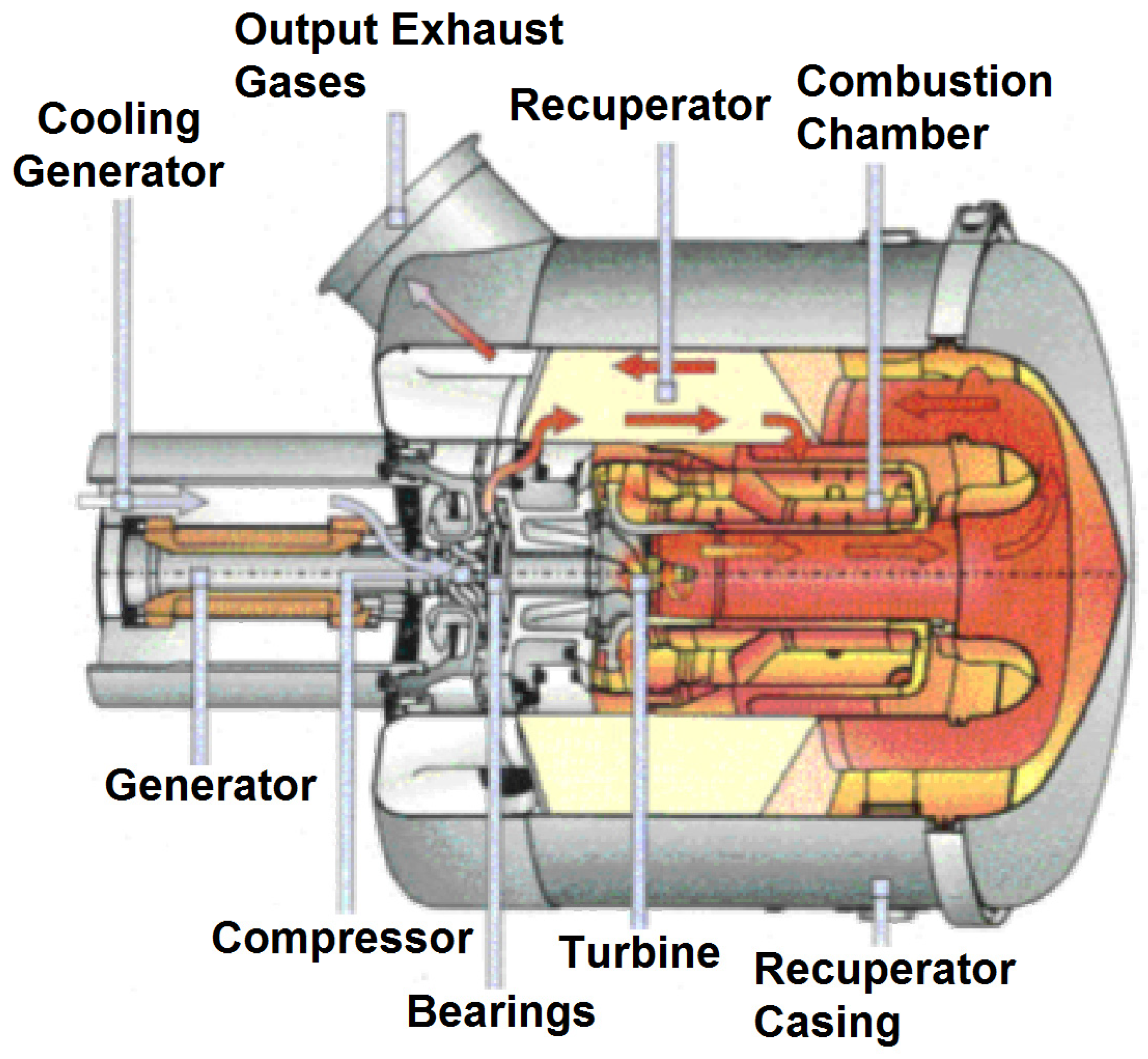
Figure 2 shows the power unit of a gas turbine unit with a built-in radial generator.
The main disadvantage of the radial generator is the large losses in steel due to the high frequency of remagnetization. With a two-pole design and a rotation speed of 96,000 rpm, the frequency of remagnetization is 1.6 kHz. It is known from the literature that magnetic losses are proportional to the frequency of remagnetization to a factor of 1.3–1.4.
Table 1 shows the electrical efficiency of Capstone generators.
The low efficiency value of 27–34% is mainly due to magnetic losses. Large heat losses have to be removed from the small volume of the generator, which complicates the design. Overheating can destroy the insulation of the stator winding and demagnetization of permanent magnets.
The second significant disadvantage of this design is the presence of resonant speeds at which the amplitude of the rotor oscillation can lead to the failure of the supports and friction of the rotating rotor against the stator, which creates a state of emergency. This effect is due to the following: the rotor has a small diameter that is limited by centrifugal forces and the strength of the bandage. For this reason, it is possible to increase the power of the generator only by increasing the axial length of the rotor. The thin and long rotor has a low stiffness, which determines the presence of critical speeds during acceleration.
The system uses gas-dynamic bearings, the principle of operation of which is based on the ascent of the rotor shaft in a thin air layer. However, this effect manifests itself only at high speeds of rotation to which the rotor must be accelerated. At low speeds, there is a dry friction of metal against metal, which dramatically reduces the reliability of the support and puts it out of action during a prolonged startup. Elastic petal supports do not solve the problem. After acceleration, they continue to wear out due to friction at high speeds.
The listed harmful factors cannot be excluded from the radial design of the generator. They can only be reduced due to design solutions and the selection of special materials. For this reason, it was decided to abandon the radial design of the generator and switch to a design that would eliminate magnetic losses and critical speeds during acceleration.
A multi-section gate generator with an axial magnetic flux and a diamagnetic anchor was chosen as the basic design for further research [
10,
11,
12,
13,
14].
Since the power of the axial generator is limited by the diameter of the rotating parts under the influence of centrifugal forces, the power required by the technical specification of the entire generator is recruited from several sections (
Figure 3). The proposed design has the following main advantages that distinguish it from the radial design:
- -
the diamagnetic armature does not contain ferro-magnetic parts, so there are no losses from demagnetization. This allows for an increase in electrical efficiency of the generator and a simplification of the design for removing heat losses;
- -
the generator rotor is a set of cylindrical sections containing permanent magnets. The surface of these sections can be used to create gas-dynamic bearings. The number of such supports can be equal to the number of generator sections. This makes it possible to multiply the rigidity of the structure and eliminate resonant frequencies, which the radial design does not allow.
The innovative design, which differs significantly from the classic radial design, requires new technical solutions for both the generator and its supports. This article is devoted to the development of a complex of supports for which a combined magnetic and gas-dynamic suspension is proposed.
2. The Principle of the Organization of Supports for the Axial Design of the Generator
The operating conditions of a micro-gas turbine installation at high rotational speeds for a long duration clearly determine the need to use non-contact bearings that do not require lubrication as supports for rotating rotors. One type of such bearings are gas-dynamic bearings. Gas-dynamic bearings are widely used in gas turbine technology and high-speed pneumatic turbomachines. The main advantages are as follows: durability in severe conditions without the need for lubrication, resistance to temperature influences, no vibrations, and almost unlimited rotation speed. Gas-dynamic supports have good rigidity, which is very important for eliminating critical frequencies, but they show their properties at high speeds sufficient for the rotor to ascend in a viscous layer of the air layer. Up to these speeds, dry friction of steel surfaces occurs, since liquid lubrication is excluded from the structure. The spraying of special heat-resistant hard alloys on these surfaces and the use of so-called petal suspensions somewhat weaken the problem, but do not solve it.
Another variant of contactless support is electromagnetic bearings, which are controlled electromechanical devices in which the stabilization of the rotor position is carried out by magnetic attraction forces acting on the rotor from the electromagnets, the current in which is regulated by an automatic control system based on the signals of the rotor movement sensors. Electromagnetic bearings are currently widely used as supports for rotating rotors, in particular, in high-speed spindles of metalworking machines, in turbocharger units, and pumps. The force developed by the magnetic bearing does not depend on the speed of rotation. The magnetic bearing works reliably even when the rotor is stationary; however, it has less rigidity and requires energy consumption when using an active bearing.
It seemed advisable to make the support combined, using the advantages from these two types of suspension and eliminating their disadvantages. At the time of startup until the rated speed is reached, an electromagnetic bearing was used. At rotational speeds from 25,000 rpm, the gas-dynamic bearing began to work. After the electric machine reached the nominal point, the electromagnetic bearing was switched off, as the generator works only on gas-dynamic bearings. These design decisions were made due to the imperfection of the gas-dynamic bearing. At low speeds, it has a high coefficient of friction, which leads to wear of the bearing. In this regard, the machine has a limited number of starts and stops. Using an electromagnetic bearing at the time of start-up, we suspended the rotor of an electric machine in a stationary state, started it up and thereby get rid of the lack of a gas-dynamic bearing. This technical solution is innovative and has not yet been used in practice for micro-gas turbine power plants.
3. Determination of the Diameter of the Rotating Parts of the Rotor Based on the Calculation of the Strength Limit from the Influence of Centrifugal Forces
Determining the maximum possible diameter of the rotor was one of the main design tasks. This is due to the fact that the electromagnetic power of a brushless machine with an axial magnetic flux is determined by the following equation [
14]:
where:
A_sr—the value of the linear load on the average diameter of the active part of the rotor containing permanent magnets;
B_sr—the value of induction on the average diameter of the active part of the rotor;
n—the rated speed of the rotor;
D_sr—the average diameter of the active part of the rotor;
L_k—the thickness of the ring of the active part of the rotor;
K_ (mod2 (180−180/m))—a dimensionless coefficient for a structure with a diamagnetic anchor and segment magnets;
K_ (eff (180−180/m))—dimensionless coefficient for switching with one disconnected phase for a multiphase armature winding;
and m—the number of phases for a multiphase armature winding.
It follows from the equation that the electromagnetic power is proportional to the diameter of the active part of the rotor squared and the thickness of the ring, which also depends on this diameter. Thus, the diameter of the rotor should be chosen very particularly to obtain the highest power of the generator section; however, it is limited by the strength of the bandage ring, which is affected by centrifugal forces.
When calculating the strength of the bandage, we will make the following assumption: we will neglect the forces of attraction of permanent magnets to the steel of the magnetic circuit and take into account only the centrifugal forces acting on the magnet. This assumption will give a pessimistic assessment of the strength of the bandage.
To determine the equations of equivalent stresses in the rotor bandage, consider the working scheme of loading the bandage (
Figure 4).
Figure 4 shows the loads acting on the bandage. From the inside, a bursting centrifugal force from the held magnets (Ftsb_magnet) acts on the bandage. Additionally, the bandage has its own centrifugal load (Ftsb_bandage).
Consider an element of an infinitesimal bandage with an indication of the stresses and forces applied to its faces.
Figure 5 shows the following parameters:
σr,
(σr + dσr),
dPy and
dPy’ are stresses and equivalent forces acting on the element in the radial direction;
σt and
dPt are stresses and equivalent forces acting on the element in the tangential direction;
dFc is the centripetal force acting on the represented element of infinitesimal magnitude;
u, and
(u + du) are deformations of the element from applied loads;
r is the radius of the element location; and
dr and
dφ are the dimensions of the element.
The centrifugal force acting on the element can be written as follows:
where:
dm—the mass of an element of infinitesimal magnitude;
ω—the angular velocity of rotation of the rotor;
p—the density of the material;
and l—the axial length of the bandage.
Equivalent force on the inner cylindrical surface:
Equivalent force on the outer cylindrical surface:
Equivalent forces on the side surfaces:
The equation of the equilibrium of forces acting on the selected element:
Considering that at small angles sin (x) = x, the equation of equilibrium in stresses takes the form:
Since the proposed expression contains two unknowns, additional equations should be written. We connect the stresses in the considered planes through deformations according to Hooke’s law:
where
and
are the relative elongations in the radial and tangential directions,
µ is the Poisson’s ratio, and
E is the elastic modulus.
On the other hand, the equations for the relative elongations through the deformations indicated in the sketch should be written from the geometry as:
Having differentiated the second equation by the radius, the equation of tangential elongations is written as:
Thus, it is possible to write an expression linking the relative elongations in the accepted directions:
Using the expression of the relationship of relative elongations and stresses, as well as the expression of the relationship of relative elongations in two directions with respect to each other, an additional equation connecting the stresses in the directions will be written as:
The solution of the system of differential equations will give expressions for stresses in the radial and tangential directions:
where the coefficients
A and
B are determined based on the boundary conditions.
For the case under consideration, the radial stresses on the inner diameter are equal to the pressure voltage from the magnets, and the radial stresses on the outer diameter are zero. The stresses on the inner diameter of the bandage created by the inertia forces of the magnets are determined by the expression:
where
r2 is the outer diameter of the magnet and
r1 is the inner diameter of the magnet.
Based on the boundary conditions, the coefficients
A and
B can be determined by the following expressions:
The obtained expressions of the coefficients allow us to obtain the equations of radial and tangential stresses. Based on the preliminary electromagnetic calculation of the axial generator, the numerical values of the dimensions of the generator rotor section are determined:
Based on the numerical solution of the obtained equations, it is possible to determine the distribution of radial and tangential stresses along the radius of the bandage at a rotational speed of the generator shaft of 70,000 rpm (
Figure 6).
The graph shows that the inner diameter of the bandage is crumpled, due to the radially directed force from the magnets. At the outer diameter, the radial stresses turn to zero. The largest of the two stresses is the tangential stress. To select a material of appropriate strength, equivalent stresses should be operated, which can be calculated using the Mises equation:
where σ
1, σ
2, σ
3 are the main stresses, determined in descending order, taking into account the sign. Thus, for the case under consideration:
The maximum equivalent voltage will be observed on the inner diameter of the bandage and will be 1379 MPa in this case.
The calculation was also verified using the Ansys structural software (
Figure 7).
For the bandage material, high-strength martensitic steel of 03N12K15M10 grade is recommended (the alloy contains components of Ni 12%, Ko 15%, and Mo 10%), which has a strength limit of 2500 MPa at a yield strength of 2400 MPa [
15]. The use of this steel ensures the strength of the structure, taking into account dynamic loads with a double margin.
4. Calculation of the Magnetic Bearing
Preliminary analysis shows that the magnetic bearing must suspend a mass of at least 30 kg. Taking into account the dynamic loads, it should be designed for a force of about 100 kg.
Since the force created by the electromagnet is proportional to the area of the interacting surfaces, the largest possible diameter of the rotating ring should be chosen for the developed cylindrical surface. Thus, it is necessary to perform a mechanical calculation of the inner ring of the proposed magnetic bearing.
To ensure a sufficient margin factor, taking into account the yield strength of electrical steel at the level of 300 MPa, the outer diameter of the inner ring of the active suspension is selected 40mm. The mechanical calculation is verified in Ansys structural software (
Figure 8).
A three-dimensional model and a sketch of a magnetic bearing are shown in
Figure 9.
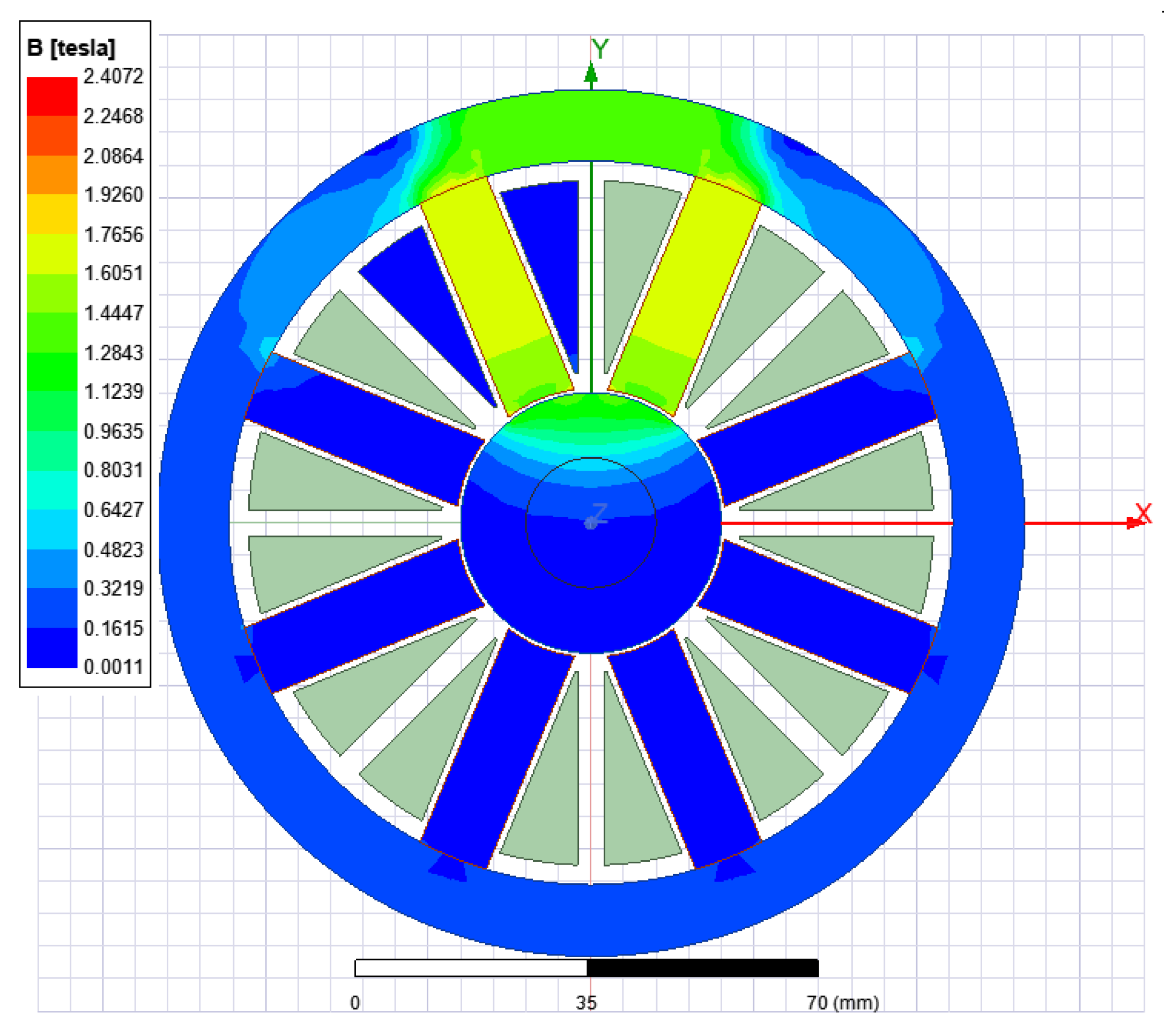
Since the analytical methods for calculating electromagnetic forces for complex magnetic systems give a large error, the finite element method was used to analyze the magnetic bearing using the Ansys desktop software package. The result of the electromagnetic calculation is shown in
Figure 10. Two operating modes are the most difficult for an active magnetic suspension. First is the switching mode, when the electromagnet must overcome twice the nominal gap between the inner ring and the stator. Second is the nominal operating mode, with the coaxial position of the inner ring with the stator and the rated current. When calculating, it should be made sure that when starting, the force developed by the electromagnet will be sufficient to lift the rotating structural elements to the coaxial position. In the second mode of operation, it is necessary to make sure that the speed of the electromagnetic suspension is maintained, in order to ensure the processing of vibrations that occur in the system. Increasing the working gap, on one hand, allows you to ensure a minimum inductance of the windings, thereby increasing the speed of the suspension. On the other hand, an increase in the working gap may make it impossible to ensure the suspension of the rotating parts of the generator when starting the suspension with a double gap (when the suspension rotor lies on the inner diameter of the stator).
As seen in
Figure 11 below, the dependence of the bearing capacity of a magnetic bearing on the displacement is not linear. It is necessary information to development of control system for proposed magnetic bearing. It is worth to mention that dependence of the bearing capacity of a magnetic bearing on the current is non-linear too. This is shown at
Figure 12. All of this will be used to design control system.
The calculation of the magnetic bearing shows that the holding force of one magnetic support can reach 500–1300 N, which is quite enough to hold a rotor weighing 30 kg.
5. Calculation of the Aerodynamic Bearing
The use of gas-dynamic bearings for micro-gas turbine installations is a well-known technical solution [
16,
17,
18,
19]. This is due to the following advantages of these supports:
- -
low gas viscosity provides relatively low friction losses, increased service life and increased energy efficiency;
- -
the temperature stability of the gas properties ensures the performance of the bearing at high temperatures.
According to the principle of operation, gas-dynamic bearings can be divided into three categories: gas-static with external supercharging, gas-dynamic without external supercharging, and hybrid. For the installation under consideration, we will choose gas-dynamic bearings without external supercharging.
It should be noted that the method of calculating gas-dynamic forces in a bearing is quite complex and is described by the system of Navier–Stokes equations [
15]:
where
t is the time;
u is the velocity vector of the gas;
p,
p,
T, and μ are its pressure, density, absolute temperature and viscosity, respectively; and
R is the universal gas constant.
For the exact solution of these equations, taking into account the geometry and small working gaps, complex software implementing the finite element method and large computing resources of computer equipment are needed. At this stage, to determine the overall dimensions and evaluate the efforts of the supports, we will use an engineering technique that has confirmed its efficiency in practice [
16]. It is developed under the following assumptions:
- -
dynamic viscosity does not depend on pressure;
- -
the flow in the gas layer is laminar;
- -
isothermal current;
- -
the inertial and gravitational forces are negligible compared to the viscosity forces.
The results of the calculation after selecting the design parameters of the bearing (length, diameter) are to determine the dependence of its bearing capacity and stiffness on the operating modes.
The diagrams of the total pressure in the gas-dynamic layer
, the bearing capacity
, and the stiffness are defined as functions of dimensionless parameters χ, σ, and ε.
The dimensionless parameters used are equal to:
where:
is the dynamic viscosity,
is the angular speed of rotation,
is the radius of the shaft,
is the static pressure,
is the gap, and
is the length of the bearing.
The calculation method was tested on the example of a turbo cooler [
16].
The bearing calculated for a turbo cooler according to the above method has the following parameters and dimensions: the rotor diameter is 74 mm, the trunnion length is 70 mm, the operating speed is 52,000 rpm, and the static load-bearing capacity is 127 N.
With regard to the proposed gas-dynamic supports having a rotor diameter of 70 mm, a length of one support of 20 mm, an operating speed of 70 thousand rpm and 9 support surfaces, the bearing capacity will be 432 N, which will ensure the ascent of the rotor with a margin of radial force. At the same time, the critical frequencies will be more than 500,000 rpm, which goes beyond the range of operating speeds.
6. Discussion
The development of an unconventional design of a high-speed multi-section axial generator is a separate study and is described in sufficient detail in other articles [
20,
21,
22,
23,
24,
25].
One of the variants of the structural design of the generator with combined supports will have the following form (
Figure 13).
Preliminary calculations for the selected geometry confirm the efficiency of the generator and the satisfaction of the main requirements of the technical specification: a nominal electric power of 100 kW at a nominal speed of 70 thousand rpm and a nominal rectified voltage of 600 V. The calculated efficiency of the generator was 96.3% in the absence of magnetic losses and electrical losses in the armature winding of 3.7 kW.
The main advantages of an axial machine compared to a radial one are as follows:
- -
no losses in steel, high efficiency, low heating losses;
- -
improvement of the layout of the turbine units;
- -
simplification of the design of an electric car;
- -
partitioning, which allows the separation of the phases in the winding;
- -
the ability to perform multiphase windings;
- -
simplification of tests by testing a single section;
- -
unification according to the line of capacities.
The disadvantages of the axial machine include the presence of a large non-magnetic gap, which requires the use of powerful permanent magnets.
We will show the advantages of an axial generator compared to a radial generator in numbers. A quantitative comparative analysis of generators of the same power of 100 kW and a rotation speed of 70,000 rpm is presented in
Table 2.
From the above table, we can conclude that the axial design has an advantage in terms of the set of positive properties and it should be recommended for mass production.
7. Conclusions
Distributed power generation sources built on the basis of high-speed gas turbine engines of small and medium power are a dynamically developing sector of the domestic and global market. At the same time, the existing mass-produced units using the radial design of the generator have reached the limit of their development; The specific energy indicators practically do not improve, the efficiency cannot be increased due to high magnetic losses, and the design requires expensive materials and complex manufacturing technology.
It is almost impossible to resolve the technical contradictions in this design. A fundamentally new design concept of this unit is needed. A micro-gas turbine installation based on a valve axial generator with combined magnetic and gas-dynamic supports is such an alternative option. It is structurally simple, technologically advanced, and has the best specific energy indicators. The complexity of implementing this innovative technology is due to insufficient scientific study of the main components, not the manufacturing technology and the use of expensive materials. It is necessary to work out the issues of optimizing the geometry, determining the optimal modes of joint operation of the magnetic and gas-dynamic bearing, the electronic control system of the entire complex, and the diagnostics of emergency modes. By solving a number of these issues, this product will be a competitor to modern analogues. The presented study is based on a gas turbine installation of 100 kW and 70,000 rpm and shows the prospects of development further in this direction.
The future of this research will be aimed at creating a software package for the development of generators of this type.


