Article

Analysis and Research on the Automatic Control Systems of Oil–Water Baffles in Horizontal Three-Phase Separators

1
State Key Laboratory of Oil and Gas Reservoir Geology and Exploitation, School of Petroleum and Natural Gas Engineering, Southwest Petroleum University, Chengdu 610500, China
2
Institute of Photovoltaic, School of Petroleum and Natural Gas Engineering, Southwest Petroleum University, Chengdu 610500, China
*
Authors to whom correspondence should be addressed.
Processes 2022, 10(6), 1102; https://doi.org/10.3390/pr10061102
Submission received: 21 March 2022 / Revised: 22 May 2022 / Accepted: 29 May 2022 / Published: 1 June 2022

Abstract

:
The three-phase separator is one of the most important pieces of equipment in the combined station of the oilfield. The control level of the oil–water interface directly affects the energy consumption of the subsequent production of the combined station and the effect of oil, gas and water separation. In order to avoid these situations, the Siemens PLC control system, configuration software WinCC and MATLAB were used. The OPC technology is used to connect communication between WinCC and MATLAB, and the genetic algorithm in MATLAB is used to obtain the optimal separation height of the oil–water interface under the produced liquid in different periods. Subsequently, through the Siemens PLC system and WinCC configuration software, the automatic control of the three-phase separator is achieved, and finally the water content of crude oil is significantly reduced. The system provides a visual interface function. In the future, it will also provide an effective simulation platform for the theoretical research and design of an automatic control system of an oilfield combined station.

1. Introduction

The three-phase separator is a widely used piece of dehydration equipment in oilfield combined stations, and its dehydration effect directly affects the heat load and product quality of the cooling heat exchangers in the station. In the later stages of oilfield development, the crude oil dehydration process becomes more and more difficult. The main reasons is that the water content of the produced fluid is as high as 90%, with which the processing capacity also increases. This causes serious economic problems, increases the load of the crude oil surface technology system and equipment, and decreases efficiency. Therefore, improving the separation technology of today’s three-phase separators is a problem that most oilfields need to overcome.
Since the three-phase separator was put into use, the control methods have been fixed value controls based on experience, which has great limitations, such as: (1) Poor self-adaptability when the production medium has physical and chemical properties and recovery fluid changes causes the production process parameters to deviate from the optimal working conditions, preventing the control target from being automatically corrected, which may cause a certain technical index to fail to meet the standard; (2) The oil–water interface control effect is poor, and failures cannot be found in time, resulting in the subsequent equipment load increases, and the efficiency of the entire oilfield system is low; (3) The level of automatic control is low, and in the case of the entire oil–water gathering and transportation system, the operating parameters lack overall optimal control. In order to save energy and reduce consumption, the water content of the oil in the three-phase separator must be reduced, and under the premise of a certain amount of oil, the power consumption of subsequent equipment must be reduced and the stability of production and the separation efficiency of the separator must be improved. In the existing control system, the automatic control system of the three-phase separator is designed to improve the applicability of the three-phase separator in the future and the economic benefit of the combined station [1].

2. Overview of the Three-Phase Separator

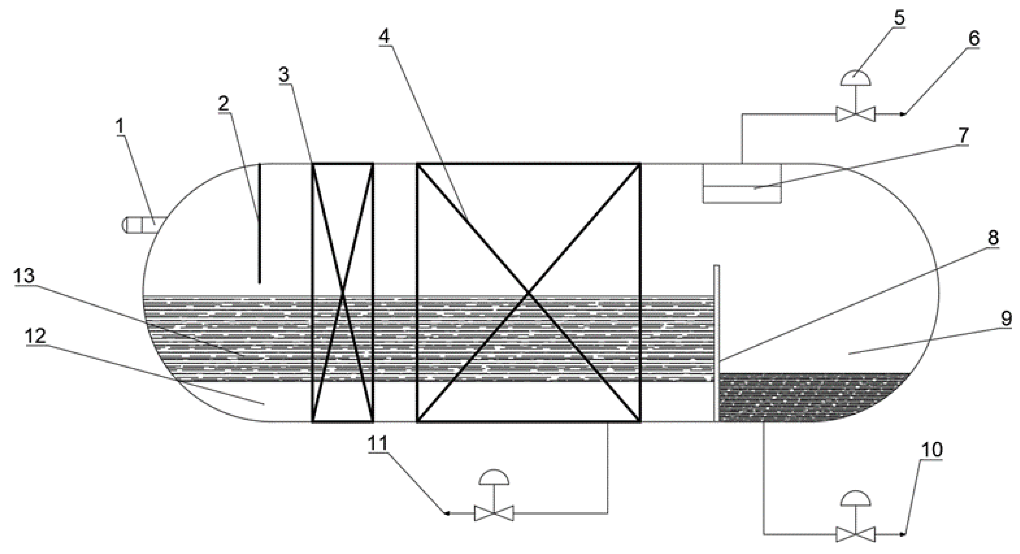
2.1. The Working Principle of the Three-Phase Separator

The main working area of the oil–gas–water three-phase separator can be divided into four parts: the inlet diversion area, the liquid collection area, the mist catcher area and the settling area [2]. Since the three phases of oil, gas and water have different physical and chemical properties (density, viscosity, particle size, etc.), in order to separate the oil, gas and water, a variety of auxiliary separation components are used in the internal design of the three-phase separator to achieve the best effect after separation in the oilfield produced fluid.
At the internal inlet of the three-phase separator, different inlet separation components, such as centrifugal and cyclone, are used to make the initial gas–liquid separation of the incoming liquid. The gas phase is separated at the inlet through the rectifier, mist trap and discharged from the gas phase port. The liquid phase undergoes collision water washing action and intensive emulsion breaking inside the three-phase separator, followed by the breakage of the emulsion interface film and the rapid floating of oil droplets to the oil phase due to the density difference. The oil–water phase fluid in the sedimentation chamber passes through the rectifier plate to the separation chamber, and a sufficient volume of free water in the separation chamber settles to the bottom to form a water layer. Strictly speaking, the upper layer is the emulsion layer formed by the emulsion that has not been demulsified. Moreover, when the crude oil is located at the upper part of the emulsion layer, the crude oil and emulsion overflow from the oil–water baffle (other separators have an intermediate layer discharge port in the separation chamber to discharge the emulsion layer) into the oil chamber and flow out of the oil phase outlet, while the sewage is discharged from the bottom pipeline [3].

2.2. Classification of Three-Phase Separators

The types of separators usually used in oilfield joint stations are horizontal, vertical and spherical separators, among which spherical separators are less used in oilfield joint stations due to the unsatisfactory separation effect, complex design structure and difficult processing. The vertical three-phase separator is suitable for separating extracted liquids containing more solids, particles and impurities, because the vertical three-phase separator is equipped with an impurities discharge port, which is generally located at the bottom of the separator for easy maintenance and cleaning. However, there are also disadvantages, as it is not suitable for processing oilfield output liquids with a high gas–liquid ratio (the gas–liquid interface space of the vertical three-phase separator is small, the agglomeration and settlement of tiny oil droplets in the gas phase will be obstructed, and the liquid content rate of the gas will rise). The key to the comparison between the horizontal three-phase separator and the vertical three-phase separator is that in the process of gas–liquid separation, the settling direction of oil-containing droplets in the gas phase is perpendicular to the flow direction of the gas phase, so that the structure of the separator allows sufficient time for the tiny droplets in the gas phase to settle into the liquid phase. In addition, the dissolved gas contained in the liquid phase can rise more fully into the gas phase space. Therefore, only the horizontal three-phase separator has been widely used in major oilfield situations because of its strong adaptability, and mature design theory and experience [4]. Figure 1 shows the structure of the horizontal three-phase separator.

3. Analysis of Motion Process of Oil–Water Separation

In the oil–water separation process of the horizontal three-phase separator, the oil–water mixture is initially separated by the separation chamber, and then enters the sedimentation chamber to form an oil–water layer. The oil layer contains tiny water droplets, and the water layer contains tiny oil droplets. The force analysis of the droplet in the oil–water layer is carried out. In the vertical direction, it is subject to its own gravity, buoyancy and motion resistance; in the horizontal direction, the inlet flow is stable, and the droplet moves at a uniform speed under the horizontal thrust. It is assumed that the droplets of the oil–water mixture entering the settling chamber of the separator are evenly distributed, also the liquid phase velocity in the horizontal direction is uniform and equal. Then, during the movement of droplets, the movements in the horizontal and vertical directions are independent of each other. Furthermore, the internal components of the separator have no effect on the movement of droplets. Therefore, the oil–water separation and sedimentation process of the separator can be understood as the addition of the vertical suspension and sedimentation motion of oil–water droplets and the uniform motion in the horizontal direction [5].

3.1. Calculation of Water Drop Settlement Height in Oil Layer

Assuming that the water droplets in the oil layer are spherical and that their initial velocity is zero, in this process, the differential equation is obtained by taking into account the water droplet’s own gravity and the resistance in the moving process, according to Newton’s second law and fluid mechanics [6]:
π 6 δ 1 3 ( ρ w ρ o ) g C D π δ 1 2 4 ρ o v 2 2 = ρ w π δ 1 2 6 d v d t
Substitute the Reynolds number formula into the calculation of Equation (1):
Re = ρ o v δ 1 μ o
When the Reynolds number Re < 2000, the sedimentation process of the droplet conforms to the Stokes sedimentation theory, and the initial boundary condition v = 0 , t = 0 is substituted into Equation (1), and simplified as:
y = g ( ρ w ρ o ) δ 1 2 18 μ o { t ρ w δ 1 18 μ o [ exp ( 18 μ o t ρ w δ 1 ) 1 ] }

3.2. Calculation of Suspended Height of Oil Droplets in Water Layer

The floating mechanism of oil droplets in the water layer is the same as the sedimentation mechanism of water droplets in the oil layer. Therefore, the calculation formula for the floating of oil droplets is:
y = g ( ρ w ρ o ) δ 2 2 18 μ w { t ρ o δ 2 18 μ w [ exp ( 18 μ w t ρ o δ 2 ) 1 ] }

3.3. Calculation of Droplet Horizontal Motion Distance

In the horizontal direction, the oil–water two-phase fluid enters the separator and the gravitational settlement zone through the fairing plate. Therefore, oil and water droplets can perform horizontal uniform speed movement with the fluid, and the calculation formula for the movement distance is:
x = w t = Q i n t / A

4. Establishment of Mathematical Model of Optimum Oil–Water Interface Height of Separator

4.1. Mathematical Modeling Idea of Optimal Oil–Water Interface Height

In the crude oil dehydration process, the separator is mainly used for the removal of a section of free water. During the operation of the separator, in addition to the separation requirements and operating conditions of the separator, the removal efficiency of the free water from the separator by the oil–water interface appears to be very important. The dehydration efficiency of the separator is related to the water phase outlet flow and the oil phase outlet flow, and the height of the oil–water interface is controlled by the water-phase outlet flow of the separator. Therefore, in order to establish the relationship between the separation efficiency of the separator and the height of the oil–water interface, it is necessary to establish the relationship between the outlet flow of the oil and water and the height of the oil–water interface. In summary, the following is a mathematical function of the relationship between the dehydration efficiency of the separator and the height of the oil–water interface:
η ( H w ) = Q w o u t ( H w ) Q L o u t ( H w ) = Q w o u t ( H w ) Q w o u t ( H w ) + Q o o u t ( H w )

4.2. Basic Assumptions

a. In the oil–water separation process, the droplet diameter of the dispersed phase is larger than the critical particle size to achieve all sedimentation separation.
b. During the oil–water separation process, the longitudinal sedimentation of the dispersed phase droplets conforms to the Stokes sedimentation theory.
c. The flow inside the separator is in a laminar flow state, the equipment has good flow characteristics, and the flow field is uniform and stable.
d. Ignore the influence of the internal components of the horizontal three-phase separator and the water washing technology on the axial flow of oil and water.
e. The schematic diagram of the axial interface of the horizontal three-phase separator is shown in Figure 2.

4.3. Establishment of Mathematical Model

4.3.1. Calculation of Water Phase Outlet Flow

The time required for the critical oil droplet d 0 to float from the bottom of the separator to the oil–water interface H w is t w . In order to make the oil droplets, achieve the necessary conditional formula: t w should be less than or equal to the time required for horizontal flow through the separator t , that is, t w t . The flow of the water phase in the sedimentation chamber of the separator is laminar, that is, the flow velocity of the water in the water-passing area is the same, and the movement of the oil droplets in the water layer in the vertical direction follows the Stokes law. In summary, the necessary conditions for the separator to separate oil droplets:
H w v o L e v 1     o r     v 1 v o L e D h D
h D = H w / D
The calculation formula of the sewage outlet flow of the separator is:
Q w o u t = A w v 1 = m A v 1 = m A L e D h D × g d o ( ρ w ρ o ) 18 μ w = m π D L e g d o 2 ( ρ w ρ o ) 72 h D μ w
m = 1 2 + 4 π ( h D 1 2 ) ( h D h D 2 ) 0.5 + 1 π sin 1 ( 2 h D 1 )
Figure 3 is a schematic diagram of the relationship between m and the dimensionless oil–water interface h D [7].
From the analysis of Figure 3, it can be seen that the value of m / h D is increased first and then decreased with the increase of the dimensionless oil–water interface, so there is a maximum value, which is calculated in the literature [7] to reach the maximum at the position of h D = 0.769 . The value of m also increases gradually with the increase of h D , but is not linear. Therefore, the final formula for calculating the egress flow is:
Q w o u t = [ 1 2 + 4 π ( H w D 1 2 ) ( H w D H w 2 D 2 ) 0.5 + 1 π sin 1 ( 2 H w D 1 ) ] π L e D 2 g d o 2 ( ρ w ρ o ) 72 H w μ w
From the analysis of Equation (10), it can be seen that the size of the sewage outlet is proportional to the difference in oil–water density, the quadratic of the oil droplet diameter, the effective length of the separator and the cross-sectional area of the separator, and is inversely proportional to the viscosity of the water, and also has a complex nonlinear relationship with the ratio of the oil–water interface height to the diameter of the separator.

4.3.2. Calculation of Oil Phase Outlet Flow

The time for the critical water droplet d w to settle from the top of the liquid phase of the separator to the oil–water interface ( H H w ) under the action of gravity is t 0 . The conditional formula for the separation of water droplets in the oil phase: the size of t 0 should be less than or equal to the time required for horizontal flow through the separator t , namely: t 0 t . Therefore, to satisfy the condition:
H H w v w L e v 2     o r     v 2 v w L e H H w
Q o o u t = A o v 2 = ( A m A A g ) v 2 = [ A ( 1 m ) A g ] L e g d w 2 ( ρ w ρ o ) 18 ( H H w ) μ o
Combining Equations (11) and (12), we get:
Q o o u t = { A [ 1 2 4 π ( H w D 1 2 ) ( H w D H w 2 D 2 ) 0.5 1 π sin 1 ( 2 H w D 1 ) ] A g } L e g d w 2 ( ρ w ρ o ) 18 ( H H w ) μ o
From the analysis of Equation (13), it can be seen that the size of the oil phase outlet is proportional to the difference in oil–water density, the quadratic of the droplet diameter and the effective length of the separator, and is inversely proportional to the viscosity of crude oil and the thickness of the oil layer ( H H w ), and also has a complex nonlinear relationship with the height of the oil–water interface and the ratio of the diameter of the separator.

4.3.3. Calculation of the Cross-Sectional Area of the Gas Phase Space

According to Figure 3, it can be concluded that the height of the gas phase space is:
H g = D H
The formula for calculating the cross-sectional area of the gas phase space is:
A g = r 2 [ π 2 arcsin ( 1 H g r ) 1 2 sin ( 2 arcsin ( 1 H g r ) ) ]
Setting the initial condition D = 2 r , and substituting Formula (14) into Formula (15), it can be calculated as follows:
A g = D 2 4 [ π 2 arcsin ( 2 H D 1 ) 1 2 sin ( 2 arcsin ( 2 H D 1 ) ) ]
To sum up: by specifying the diameter of the separator D , the effective length of the separator L e , the height of the gas-liquid interface H , the density of the oil and water phases ρ o , ρ w , the viscosity of oil phase is μ o , the viscosity of water phase is μ w , the critical water droplet size is d w , and the critical oil droplet size is d o , which can calculate the outlet flow of oil and water and the size of gas phase space.

4.3.4. Mathematical Model

Substitute Equations (10) and (13) into Equation (6) to obtain the optimal calculation formula of oil–water interface height and dehydration efficiency as shown in Formula (17):
{ max η = π m D 2 d o 2 ( H H w ) μ o H w μ w [ π D 2 ( 1 m ) 4 A g ] d w 2 + m π D 2 d o 2 ( H H w ) μ o A m o g : A g = D 2 4 [ π 2 arcsin [ 2 H D 1 ] 1 2 sin ( 2 arcsin ( 2 H D 1 ) ) ] m = 1 2 + 4 π ( H w D 1 2 ) [ H w D H w 2 D 2 ] 1 2 + 1 π sin 1 [ 2 H w D 1 ]

4.4. Setting of Constraints

The setting of the constraint conditions can not only ensure the rationality of the mathematical model calculation but also optimize the key to optimizing the dehydration efficiency of the separator, which mainly comes from the operating conditions of the horizontal three-phase separator and the physical properties of crude oil.
(1) During the operation, it is necessary to ensure that the density of the separator inlet liquid, the fluid temperature, and the like are always constant.
(2) In order to avoid the separation requirements of the oil–water separated from the horizontal three-phase separator, the range of the height of the oil and water interface is controlled around 0.1 m.
(3) The internal pressure of the horizontal three-phase separator is 0.3 MPa and the internal temperature remains at 50 °C, thereby ensuring that the effect of crude oil viscosity on the water phase flow can remain stable.

5. Design of Automatic Control of Three-Phase Separator

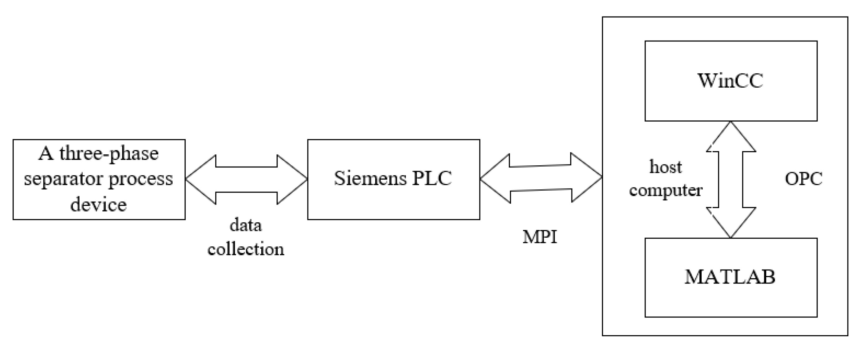
5.1. Composition of the Control System

The controlled objects of the three-phase separator automatic control system generally include the height of the oil–water baffle and the liquid level of the oil chamber. The purpose of the control is to accurately control the height of the oil–water interface at a given value, thereby achieving the optimal separation efficiency [8,9,10]. Its control system structure is shown in Figure 4.

5.2. PLC System Hardware

As the hardware basis of the control system, it is particularly important to select the appropriate PLC as the controller. According to the actual requirements of the system, the three-phase separator in the station adopts the Siemens PLC system to realize communication through an Ethernet network and WinCC configuration software. The Siemens PLC system mainly realizes the data acquisition, communication, control and other functions of field sensors. [11]. When communicating with the host computer software MATLAB, since MATLAB does not support Siemens’ communication protocol, it is necessary to install SIMATIC NET software on the host computer and set up a connection between the host computer and the PLC, with the PLC as the server and MATLAB as the client. Simulink builds the controlled object and completes the PID control algorithm between the two through the OPC communication protocol, and the host computer WinCC can read the data and display the control process [11,12].

5.3. Configuration Software

The host unit state monitoring software selects the Window Control Center (SIMATIC WinCC). The main functions include process monitoring, communication with the PLC, standard interface, programming interface, report design, variable recording and alarm archiving. Connect the Siemens PLC system via Ethernet. It is an HMI component in the SIMATIC PCS 7 process control system and other Siemen control systems. All built-in operation and management functions can be configured simply and efficiently, and can be continuously extended based on the web, adopting open standards and easy integration.

5.4. Fuzzy Optimization Control Software

In order to improve the oil–water separation efficiency and optimize the control of the horizontal three-phase separator, the OPC toolbox module sub-library (including OPC read block, OPC write block, OPC configuration and OPC quality parts) is inherited by using the OPC toolbox in MATLAB software and Simulink. MATLAB is a powerful client to achieve control system analysis and algorithm writing. With this function, it can automatically read the data of the configuration software, establish the mathematical models such as the height of the oil–water interface, the outlet flow and the cross-sectional area of the gas phase space in the horizontal three-phase separator, establish the fuzzy control rules for adjusting the water output according to the changes of the oil–water interface and the liquid inlet in a short time, and make use of the data of the physical size, oil output flow and water output flow of the horizontal three-phase separator. It can also calculate the optimal height of the oil–water interface for a certain period of time, and then control the height of the oil–water baffle according to the fuzzy control rules, thereby improving the oil–water separation efficiency of the three-phase separator [13]. Figure 5 shows the functional design of the optimization control software.

5.4.1. OPC Communication

In MATLAB, you can write code in M language to complete the setting of OPC client, set the interface through OPC tool, and build an OPC function module in Simulink to realize the function [14].

5.4.2. Mathematical Algorithm

In Equation (17) of the established mathematical model, the dehydration efficiency is a univariate function of the height of the oil–water interface, but there is a copied nested relationship in the mathematical model, and the formula after derivation and calculation by analytical method is still a complex nested relationship formula. Therefore, the mathematical model of dehydration efficiency is solved by genetic algorithm.
In a genetic algorithm, the initial population is formed after compilation, and then the genetic operations are carried out. The main task of genetic operation is to select, crossover and mutate the individuals of the population according to their environmental fitness to realize the evolution of the survival of the fittest. This process can make the solution of the objective function optimized from generation to generation until the optimal solution is found.
The programming process of genetic algorithm is as follows:
(1) The parameter population size, number of variables, crossover probability, mutation probability and the termination evolution algebra of genetic operation of genetic algorithm are assigned.
(2) The control range of constraints and variables are set.
(3) Within the set variable range, the residual initial population is substituted into the fitness function and the fitness is calculated.
(4) The proportional selection operator is executed, crossover operator and mutation operator for selection, crossover and mutation operations.
(5) After the fourth step, the fitness value of each individual in the local optimal solution is obtained, and the optimal individual is saved.
(6) Then, it is judged on whether or not it meets the termination evolution algebra of a genetic algorithm. If not, return to the fourth step and recalculate until the optimal solution is obtained.

6. Discussion

6.1. Basic Data

The schematic diagram of the horizontal three-phase separator based on the Liuzan Union Station is shown in Figure 1, and the structural data and physical properties parameters of the separator are shown in the following Table 1 [15,16]:
Table 2 shows the daily operation data recorded under the stable operation of the three-phase separator of the Liuzan Union Station on a certain 15th day of the month.

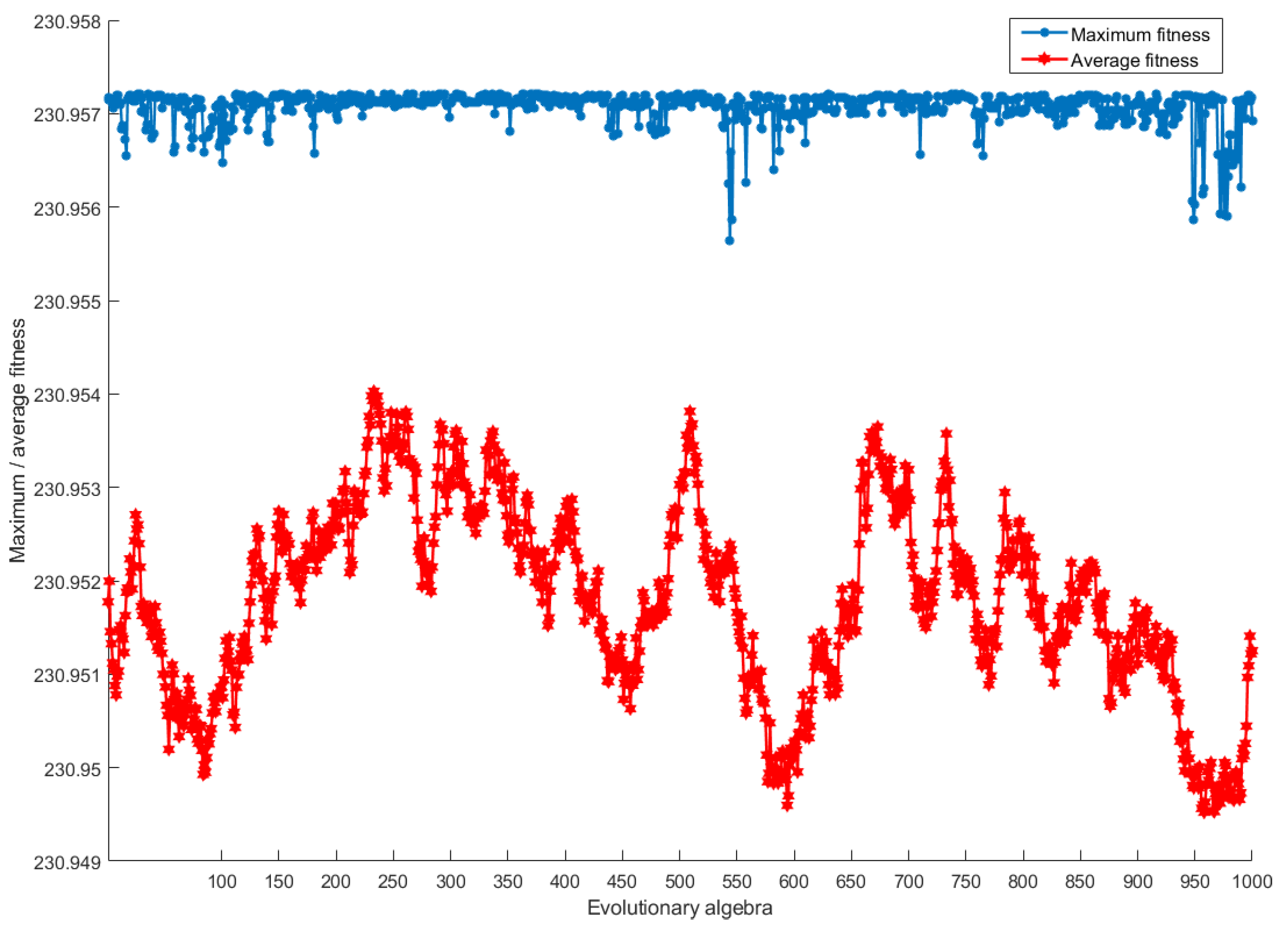
6.2. Result Analysis

The program sets the initial population size as 200, the maximum evolutionary algebra as 1000 steps, the crossover probability as 0.9, and the mutation probability as 0.09. Then the digital model is substituted into MATLAB, by setting the initial population size to 200 and the maximum algebra to 1000. Finally, the basic data in Table 1 and the operation data in Table 2 are substituted into the genetic algorithm, and the final optimization parameters, such as separation efficiency and the fitness curve of the fitness function in the iteration of the genetic algorithm, are obtained through the fitness function Equation (17), as shown in Figure 6.
According to Figure 6 of the fitness curve, obtained after the operation of genetic algorithm, we can conclude that: generally, if the average fitness and maximum fitness of the population in the evolution process converge on the curve, it means that the convergence of the algorithm is very smooth and there is no oscillation. On this premise, the maximum fitness individual has not evolved for several consecutive generations, indicating that the population is mature [17,18].
The genetic algorithm is used to calculate that when the height of the oil–water interface is controlled at 2.0691 m, it is located at 0.65 times the diameter of the separator. At this time, the dehydration efficiency of the separator is 95.71%. The comparative analysis of the operation effect of the separator before and after optimization is shown in Table 3. The data before optimization is the average value of stable operation for 15 days.
According to the analysis in Table 3, when the operating conditions of the separator remain unchanged, the height of the oil–water interface is reduced from 2.2 m before optimization to 2.069 m, and the dehydration efficiency of the three-phase separator is increased to 95.71%. After optimization, the instantaneous sewage outlet flow is increased by 0.09121 m3/s, and the average daily dewatering of the separator is increased when the inlet flow of the separator is unchanged. After optimization, the change of sewage outlet flow is due to the reduction of water phase space due to the low oil–water interface, the residence time of water phase in the sedimentation chamber becomes smaller, and the oil content of sewage after preliminary oil–water separation in the sedimentation chamber is significantly reduced, the viscosity of water is small and the flow characteristics are good, so the sewage outlet flow will become larger. However, there is no obvious change before and after the optimization of oil phase flow. The reason is that the water content of crude oil is reduced after chemical demulsifier, water washing and coalescence sedimentation, and the viscosity of crude oil is high, so the flow of crude oil will not have an obvious impact with the small change of the oil–water interface of the separator, this view is also discussed in reference [19].

7. Conclusions

Because the three-phase separator of the station was put into operation too early, its separation efficiency was much lower than that of the source. In order to improve the separation efficiency of the three-phase separator, the automatic control system is added to improve the operation mode of the whole oil, gas and water separation. The improvement results show that the dehydration efficiency is greatly improved, and the oil content of sewage is significantly reduced. This reflects the characteristics of low investment and convenient adjustment. This method does not need strict and accurate oil–water level measurement data, and does not need the professional knowledge and skills of operators. It also has strong anti-interference ability. Compared with the traditional system, this system has the following innovation points: (1) Through the genetic algorithm in MATLAB, the optimal oil–water interface separation point of the oil–water mixture in different states is automatically calculated, so that it can be accurately separated and will not cause waste of resources in the later stage. (2) Using the Siemens PLC to achieve communication through the Ethernet network and WinCC configuration software, the Siemens PLC system mainly realizes the data acquisition, communication, control and other functions of on-site sensors. And through the host computer WinCC configuration software, to achieve process monitoring, communication with PLC, standard interface, programming interface, report design, variable recording and alarm archiving. If the system can operate normally, it will improve the separation efficiency of the three-phase separator in the joint station, which has extensive project research significance, realizes the process automation of the oilfield station, and has good application prospects.

Author Contributions

Conceptualization, F.W.; methodology, F.W.; software, F.W.; validation, F.W.; formal analysis, F.W.; investigation, C.H.; resources, K.H.; data curation, K.H.; writing—original draft preparation, F.W.; writing—review and editing, K.H.; visualization, H.L. All authors have read and agreed to the published version of the manuscript.

Funding

This research received no external funding.

Institutional Review Board Statement

Not applicable.

Informed Consent Statement

Not applicable.

Data Availability Statement

The data presented in this study are available on request from the corresponding author.

Acknowledgments

Thanks to Huang Kun for his careful guidance and advice in the writing of the thesis.

Conflicts of Interest

The authors declare no conflict of interest.

Nomenclature

δ 1 Diameter of settled water droplet
δ 2 The floating diameter of oil droplets in the water layer
μ w Viscosity of water phase
μ o The viscosity of the crude oil
ρ w Water phase density
ρ o Oil phase density
A Axial area of separator
A g Gas phase space cross-sectional area
A w Liquid phase cross-sectional area of separator
C D Drag coefficient of droplet movement, dimensionless
D Inner diameter of separator
d o Critical diameter of oil droplet
d w Critical particle size of water droplets
H Liquid phase height of separator
H g Gas phase sectional area height of separator
H o Sectional area and height of separator oil phase
H w Oil water interface height of separator
h D The height of dimensionless oil–water interface
L e The effective length of the separator
m Infinite area of water passage
MATLABMatrix Laboratory
OPCObject Linking and Embedding(OLE) for Process Control
PIDProportion Integration Differentiation
PLCProgrammable Logic Controller
Q i n Inlet flow
Q L o u t ( H w ) Functional relationship between total liquid flow at outlet and H w
Q o o u t ( H w ) Functional relationship between oil phase outlet flow and H w
Q w o u t ( H w ) Functional relationship between water phase outlet flow and H w
Q w o u t The sewage treatment capacity of the separator
t Oil, water droplet horizontal movement time
v Water droplet settling velocity
v o The floating velocity of oil droplets
v 1 The horizontal flow velocity of the water phase
v 2 Horizontal velocity of oil droplets
v w Floating speed of oil droplets
w Oil, water droplet horizontal flow rate
WinCCWindows Control Center

References

  1. Qi, G. Design and development of optimal control system for three-phase separator. Foreign Electron. Meas. Technol. 2021, 40, 78–81. [Google Scholar]
  2. Bai, Y.; Zhang, R. Application of oil gas water three-phase separator in Oilfield. Chem. Manag. 2020, 12, 215–216. [Google Scholar]
  3. Guo, S.; Wu, J.; Yu, Y.; Dong, L. Research progress of oil gas water three-phase separator. Pet. Mach. 2016, 44, 104–108. [Google Scholar]
  4. Zhang, Y.; Yang, J.; Lei, K.; Ma, L. Theoretical analysis and interface height control of three-phase oil-water separator. Chem. Manag. 2022, 1, 136–139. [Google Scholar]
  5. Xiao, R.; Wang, Q. Understanding and practice of oil gas water three-phase separator. Oilfield Surf. Eng. 1993, 7, 23–27. [Google Scholar]
  6. Lv, Y.; He, L.; Ding, S.; Guo, X.; Cheng, H. Study on droplet size and pressure drop in crude oil water dispersion. J. Eng. Thermophys. 2013, 34, 472–475. [Google Scholar]
  7. Powers, M.L. Analysis of Gravity Separation in Freewater Knockouts. Spe Prod. Eng. 1990, 5, 52–58. [Google Scholar] [CrossRef]
  8. Lu, D.; Ji, X. Automatic Control Principle and Design; Shanghai Science and Technology Press: Shanghai, China, 1978. [Google Scholar]
  9. Gao, R. Development of Dynamic Simulation System for Oil Field Combined Station; China University of Petroleum: Beijing, China, 2011. [Google Scholar]
  10. Jiao, B. Research on Control System of Horizontal Three-Phase Separator for Oil, Gas and Water; Jilin University: Changchun, China, 2012. [Google Scholar]
  11. Wang, Z.; Zhou, B.; Wang, W. Design of intelligent measurement and control system of fire tube furnace based on PLC. Electron. Meas. Technol. 2020, 43, 119–125. [Google Scholar]
  12. Fu, J.; Xu, M. Design of vertical stable carrying platform based on PLC. Foreign Electron. Meas. Technol. 2020, 39, 113–116. [Google Scholar]
  13. Zhu, J. Design of water level fuzzy control system based on WinCC and MATLAB. Mech. Eng. Autom. 2015, 4, 183–184. [Google Scholar]
  14. Fu, P. Design of control system based on OPC MATLAB and Siemens 1215c PLC. Shandong Ind. Technol. 2014, 24, 147. [Google Scholar]
  15. Chen, G.; Xie, H.; Lu, X. Application of Matlab genetic algorithm toolbox in nonlinear optimization. Comput. Technol. Dev. 2008, 18, 246–248. [Google Scholar]
  16. Li, M. Explain in Detail the Application of MATLAB in Optimization Calculation; Electronic Industry Press: Beijing, China, 2011. [Google Scholar]
  17. Wang, J. Research on Fuzzy Optimization Technology of Production and Operation Parameters of Oil and Gas Gathering and Transportation System; Northeast Petroleum University: Daqing, China, 2017; pp. 7–12. [Google Scholar]
  18. Hong, X.; Shen, S. Application and theoretical basis of PID control. Control. Eng. 2003, 10, 37–42. [Google Scholar]
  19. Backi, C.J.; Skogestad, S. A simple dynamic gravity separator model for separation efficiency evaluation incorporating level and pressure control. In Proceedings of the American Control Conference(ACC), Seattle, WA, USA, 24–26 May 2017; pp. 2823–2828. [Google Scholar]
Figure 1. Structural diagram of horizontal three-phase separator. 1—oil and gas water mixture inlet; 2—inlet member; 3—rectifying member; 4—coalescence member; 5—pressure control valve; 6—gas phase outlet; 7—capping; 8—oil baffle; 9—oil room; 10—oil phase exit; 11—aqueous outlet; 12—water; 13—oil and emulsion.
Processes 10 01102 g001
Figure 2. Schematic diagram of the axial interface of the horizontal three-phase separator.
Processes 10 01102 g002
Figure 3. The relationship between h D and m , m / h D .
Processes 10 01102 g003
Figure 4. Control system structure.
Processes 10 01102 g004
Figure 5. Optimize the function design of control software.
Processes 10 01102 g005
Figure 6. Schematic diagram of maximum/average fitness curve law.
Processes 10 01102 g006
Table 1. Separator and physical parameters of crude oil.
ItemDataItemData
Separator Size (mm)3200 × 14,000Design Capacity (m3/d)10,000
Liquid Phase Section Height (m)2.73Crude Oil Density (kg/m3)853.6
Operating Pressure (MPa)0.3Water Phase Density (kg/m3)1000
Operating Temperature (℃)50Water Phase Residence Time (min)24
Crude Oil Viscosity (mPa·s)6.59Oil Phase Residence Time (min)100
Water Phase Viscosity (mPa·s)0.6
Table 2. Liuzan Union Station three-phase separator 15th operation data record table.
DateTemperature
(℃)
Pressure
(MPa)
Oil Output
(m3)
Water Output (m3)Liquid Inlet
(m3)
6.16500.376076498409
6.17500.372876368364
6.18500.366976568325
6.19500.386577248589
6.20500.364475968240
6.21500.385776588515
6.22500.382276678489
6.23500.359976118210
6.24500.345475818035
6.25500.382076158435
6.26500.373676738409
6.27500.365576058260
6.28500.359575498144
6.29500.361875738191
6.30500.363677678403
Average value500.3697.27637.38334.5
Table 3. Comparative analysis of separator before and after optimization.
Operating Temperature
(℃)
Operating Pressure
(MPa)
Oil–Water Baffle Height
(m)
Sewage Outlet Flow
(m3/s)
Oil Phase Outlet Flow
(m3/s)
Dehydration Efficiency
(%)
Before optimization500.32.20.88380.0080791.63
After optimization500.32.06910.179590.0080595.71
Publisher’s Note: MDPI stays neutral with regard to jurisdictional claims in published maps and institutional affiliations.

