Review

Novel Approaches Concerning the Numerical Modeling of Particle and Cell Separation in Microchannels: A Review

by
Ioannis H. Karampelas
1 and
Jenifer Gómez-Pastora
2,*
1
Nemak USA, Inc., 3101 S Taylor Dr., Sheboygan, WI 53081, USA
2
Department of Chemical Engineering, Texas Tech University, 807 Canton Ave, Lubbock, TX 79409, USA
*
Author to whom correspondence should be addressed.
Processes 2022, 10(6), 1226; https://doi.org/10.3390/pr10061226
Submission received: 30 May 2022 / Revised: 12 June 2022 / Accepted: 13 June 2022 / Published: 20 June 2022
(This article belongs to the Section Biological Processes and Systems)

Abstract

:
The demand for precise separation of particles, cells, and other biological matter has significantly increased in recent years, leading to heightened scientific interest in this topic. More recently, due to advances in computational techniques and hardware, numerical simulations have been used to guide the design of separation devices. In this article, we establish the theoretical basis governing fluid flow and particle separation and then summarize the computational work performed in the field of particle and cell separation in the last five years with an emphasis on magnetic, dielectric, and acoustic methods. Nearly 70 articles are being reviewed and categorized depending on the type of material separated, fluid medium, software used, and experimental validation, with a brief description of some of the most notable results. Finally, further conclusions, future guidelines, and suggestions for potential improvement are highlighted.

1. Introduction

The capacity to precisely separate and manipulate suspended particles, cells, or other biological matter is a critical process in many applications of biology and medicine for disease diagnosis, genetic analysis, drug screening and delivery, tissue engineering, and therapeutics [1,2,3,4]. Recent research has been devoted to the manipulation, concentration, focusing, separation, isolation, and fractionation of particulate material such as micro- and nanoparticles, cells, liposomes, microvesicles, viruses, etc., using microfluidic devices, i.e., the so-called lab on chip devices [5,6,7]. Microfluidics-based cell/particle manipulation technologies have shown great potential due to the low sample and reagent volume consumption, low waste generation, high product purity, high sensitivity and selectivity, ease of use, and short isolation time, in addition to being able to perform particle/cell analysis at the single-cell level [8,9,10,11,12,13]. Moreover, downscaling of sorting systems enables less laboratory space, and the integration of multiple tasks and operations within the same device is possible, which not only increases the precision of the analysis but also improves the accuracy, reliability, and reproducibility of sample preparation procedures [14,15]. Thus, controlling the motion and position of these materials within fluids in microchannels possesses great importance in the previous fields, especially for the development of low-cost and portable diagnostic tools that can be used at the point of need [16,17,18].
Among the different approaches developed to separate and manipulate particles and cells, the use of active forces (i.e., magnetophoresis, dielectrophoresis, or acoustophoresis) presents several advantages over passive techniques. Passive techniques are usually restricted to separating the material based on size or compressibility, which may cause cell damage or channel obstruction; they require complex microchannels that lack reconfigurability to suit various target entities, large device footprints, long operation times, and low accuracy [14,19,20]. Due to these limitations, active sorting techniques are widely investigated as potential alternatives. Active sorting methods utilize an external field to manipulate the particles; the target material is selectively trapped (or displaced laterally) based on a field-dependent physical property inside the channel (or collected at the target outlet) [14,21]. These techniques pose many benefits. On the one hand, they are relatively fast and accurate, able to manipulate particles and cells within simple and low-cost microchannels, and at the same time, they are non-invasive (contactless), label-free (as in most cases it is not needed to use antibodies or beads), and exhibit high biocompatibility such that the integrity, functionality, and viability of cells and biological compounds can be kept preserved during the process [14,16,19]. The main disadvantage of active systems is that they require, in some cases, power and control [8]. Nevertheless, active forces generated by creating electrical, magnetic, and acoustic fields within the microdevice have been employed in various medical, biological, and environmental applications [4,21,22,23].
However, in contrast to the progress in experimental active force-based microfluidic approaches, the underlying theoretical aspects need further investigation. There are still limitations to the microfluidic particle separation technology, although promising progress has been made over the past several decades [24]. To achieve these breakthroughs, a deeper understanding of how the various key parameters involved in the process influence the separation performance is required. Indeed, the investigation should be focused on understanding the separation and manipulation mechanisms that allow the use of Computational Fluid Dynamics (CFD) software to predict the device performance before fabrication [25]. Using numerical models should be considered a favorable first step for designing a chip as it saves both time and cost [8,26]. Numerical simulations allow researchers to define how design parameters would improve the device functionality, thus minimizing costly prototyping iterations [27]. These models can also be used for the interpretation of experimentally observed phenomena or for optimizing their performance. Most of the previous works focused on experimental designing and testing were solely based on trial-and-error processes. There is a need to develop efficient models capable of optimizing the preliminary design factors of chips so that precise particle/cell manipulation and separation can be achieved [8]. Owing to this, an impressive growing number of works dealing with the numerical modeling of the process have been reported in the last decade.
This work reviews the recent advances in numerical modeling of microfluidic particle and cell separation using active separation methods (those that utilize external fields to drive particle and cell separation). A bibliographic survey [28] using the keywords ‘‘simulation”, ‘‘particle separation”, “cell separation”, and ‘‘microfluidics” was carried out. As depicted in Figure 1, more than 600 papers have been published since 2003, most of them reported in the last 5 years. To provide a global overview of the state of the art, nearly one hundred scientific publications published in the last 5 years (from 2017 to 2021) and employing novel models for the description of acoustophoresis, magnetophoresis, and dielectrophoresis (the most common active techniques for the separation of cells and particles) have been reviewed [1,2,3,5,8,9,11,14,15,16,19,20,24,26,27,29,30,31,32,33,34,35,36,37,38,39,40,41,42,43,44,45,46,47,48,49,50,51,52,53,54,55,56,57,58,59,60,61,62,63,64,65,66,67,68,69,70,71,72,73,74,75,76].

2. Principles and Numerical Modeling of the Active Microfluidic Particle Separation

In this section, the underlying mechanisms behind active particle and cell separation are established. First, we briefly describe the different approaches used to model the process. Second, the main forces acting on the material during separation are introduced. Finally, the numerical methods most widely applied are briefly described. It should be noted that the theoretical models described in this section can be implemented into different commercial and custom solvers that describe the particle and cell motion as a function of multiple variables and parameters. Thus, they enable the design and optimization of the separation process.

2.1. Approaches to Model the Microfluidic Separation of Suspended Particles/Cells

It should be noted that there are mainly two approaches to model the separation of particles and cells in microfluidics. First is the Lagrange method, the most widely used approach to model the active separation of particles and cells in microfluidics. This approach neglects Brownian motion and solves the Newtonian equation of motion of single particles [77]. The second approach involves using an Eulerian approach in which particles are modeled collectively in terms of a time-dependent spatially varying concentration, which is calculated by a partial differential equation that accounts for the drift force and the Brownian diffusivity of the particles [78]. The Euler approach is generally used for nanoscale particle separation, where the effects of Brownian motion are significant. Due to the size of the particles employed in most studies dealing with microfluidic separation, which in most cases is hundreds of nanometers, the Brownian forces are negligible [61]. Thus, in this work, we only consider the Lagrangian approach, where particles are modeled as discrete units, and the trajectory of each particle is estimated by applying the classical Newtonian dynamics [26,52,71,79]:
m p dv p dt = F d + F g + F separation
where mp and vp denote the mass and velocity of the cell/particle and Fd, Fg and Fseparation represent the drag force, gravity force, and the force driving the separation, i.e., the active force. It is to be mentioned that since the characteristic timescale of the acceleration phase of the microparticles’ and cell’s motion is much smaller than the time scale of the variation of the external forces, the particle always moves at a terminal velocity which can be obtained from the balance of gravity, drag, and separation forces [61]. Depending on the specific application and working conditions, other forces might need to be included (such as particle-fluid or particle-particle interactions), although in most scenarios, including the drag and separation forces will suffice to estimate the separation efficiency of the device. It is widely adopted that when the volume fraction of the dispersed particles is lower than 10%, the particle-particle interaction can be neglected [27]. More specifically, particle-particle and particle-fluid interaction can be ignored for particle suspensions with a small particle volume concentration of less than 5%, which is the case in most applications [31]. Equations to develop these forces are in the following.

2.2. Forces Acting on the Material

2.2.1. Fluid and Gravity Forces

The forces driving the particle and cell separation inside the microchannel are balanced with the drag force on the particle in the fluid. For a spherical particle in a laminar flow regime, the Stokes drag force is [19,52,80]:
F d = 6 π η rv
where η is the fluid viscosity, r is the particle’s radius, and v is the velocity vector for the particle relative to the fluid.
To compute the drag force, the fluid velocity field within the device needs to be calculated. The commercial simulation software packages used to simulate the process solve the Navier-Stokes and continuity equations using an Eulerian approach [27,79]:
v f = 0
ρ f ( v f t + v f v f ) = P + ( η v f )
where vf and ρf represent the fluid velocity and density, and P is pressure.
A more sophisticated Lagrangian tracking of the particles and cells can be achieved by coupling the particles with the Eulerian solution of the Navier-Stokes equations for the carrier fluid by accounting for the particle-fluid momentum exchange between phases [27,33]. The resulting model, involving the simultaneous solutions for the Eulerian fluid flow and the Lagrangian tracking of dispersed particles, is usually referred to as the Discrete Particle Model (DPM). For Lagrangian-Eulerian models, the discrete and continuous phases are simulated using different numerical discretization and gridding schemes [27]. With that, the iterative exchange of variables between phases can only be achieved using approximated Lagrangian-Eulerian transformations and, therefore, adds for numerical errors [27].
Finally, and although it is neglected in most of the studies, the gravity force, including buoyancy, can be computed as the difference between the weight of an immersed particle and an upward buoyancy force exerted by fluid, given by [31]:
F g =   V p ( ρ p ρ f ) g
where Vp represents the particle volume, ρp is the particle density, and g is the acceleration due to gravity.

2.2.2. Separation Forces

Different separation forces can be applied to manipulate or separate solid particles and cells from fluids. Among the most common active separation techniques are those that employ magnetic, electric, and acoustic fields. These forces are presented below.

Magnetic Forces

Magnetophoresis is one of the most promising approaches to separating particles and cells within microfluidics [81]. It can be defined as the migration of a material in the presence of a nonuniform magnetic field. The magnetic force acting on unsaturated particles or paramagnetic cells can be expressed as [27]:
F mag = 1 2 V p μ 0 χ H 2
where Δχ is the difference between the medium and the particle/cell magnetic susceptibility, µ0 is the magnetic permeability of the space, and H represents the intensity of the applied magnetic field. If the magnetic susceptibility of the particle is greater than that of the carrier liquid, Δχ > 0, and positive magnetophoresis occurs, i.e., the magnetic particle is attracted towards the high magnetic field potential. On the contrary, in negative magnetophoresis, the migration of non-magnetic (diamagnetic) particles in a magnetic fluid is carried out, and Δχ < 0 [38]. Negative magnetophoresis can separate diamagnetic particles such as polymer beads and biological material, including cells in a paramagnetic medium such as a ferrofluid solution, without the need for magnetic labels.
It should be noted that in the majority of studies, positive magnetophoresis is employed, and thus, superparamagnetic beads are commonly the material that needs to be separated. Superparamagnetic beads are soft-magnetic materials that do not retain their magnetic moment after the applied magnetic field is removed [31,79]. The magnetization of the bead is a function of the applied magnetic field. It is a linear function of the field (χH) up to a magnetic flux of approximately 0.1–0.5 T [31,82], after which it remains nearly constant, with a saturation magnetization of Msat that is independent of the applied magnetic field [31]. In the saturation region, Equation (6) needs to be replaced by the following equation [82]:
F mag = μ 0 V p M sat H
It should be noted that magnetic cell separation devices are not sensitive to factors such as ionic concentration, pH, and surface charge, allowing operation in a wide range of these parameters [31,79]. However, in most cases, separating biomaterials and cells requires the prior labeling of the material using magnetic beads. This is because biological materials (except for red blood cells (RBCs) and iron proteins or magnetostatic bacteria) usually exhibit diamagnetic properties and are not greatly affected by the applied magnetic field (unless suspended in a paramagnetic medium or ferrofluid) [31]. In these cases, the magnetic beads are specifically designed to target the cell or biomolecule that needs to be separated. Magnetic beads with diameters of 50–2500 nm, made of superparamagnetic iron oxide nanoparticles (SPIONs) embedded in a polymer matrix (e.g., polystyrene), with a net magnetic volume fraction typically less than 20% vol., are commercially available and purchased in most of the recently published research works from manufacturers [29]. Before the magnetic separation, these beads are incubated with the biological material of interest. The resulting biological material–bead complex is not spherical, making it difficult to calculate some forces, such as the drag force. However, depending on the sizes of the materials under consideration, simple approaches can be used to estimate the forces acting on the complex without introducing a significant error [31].
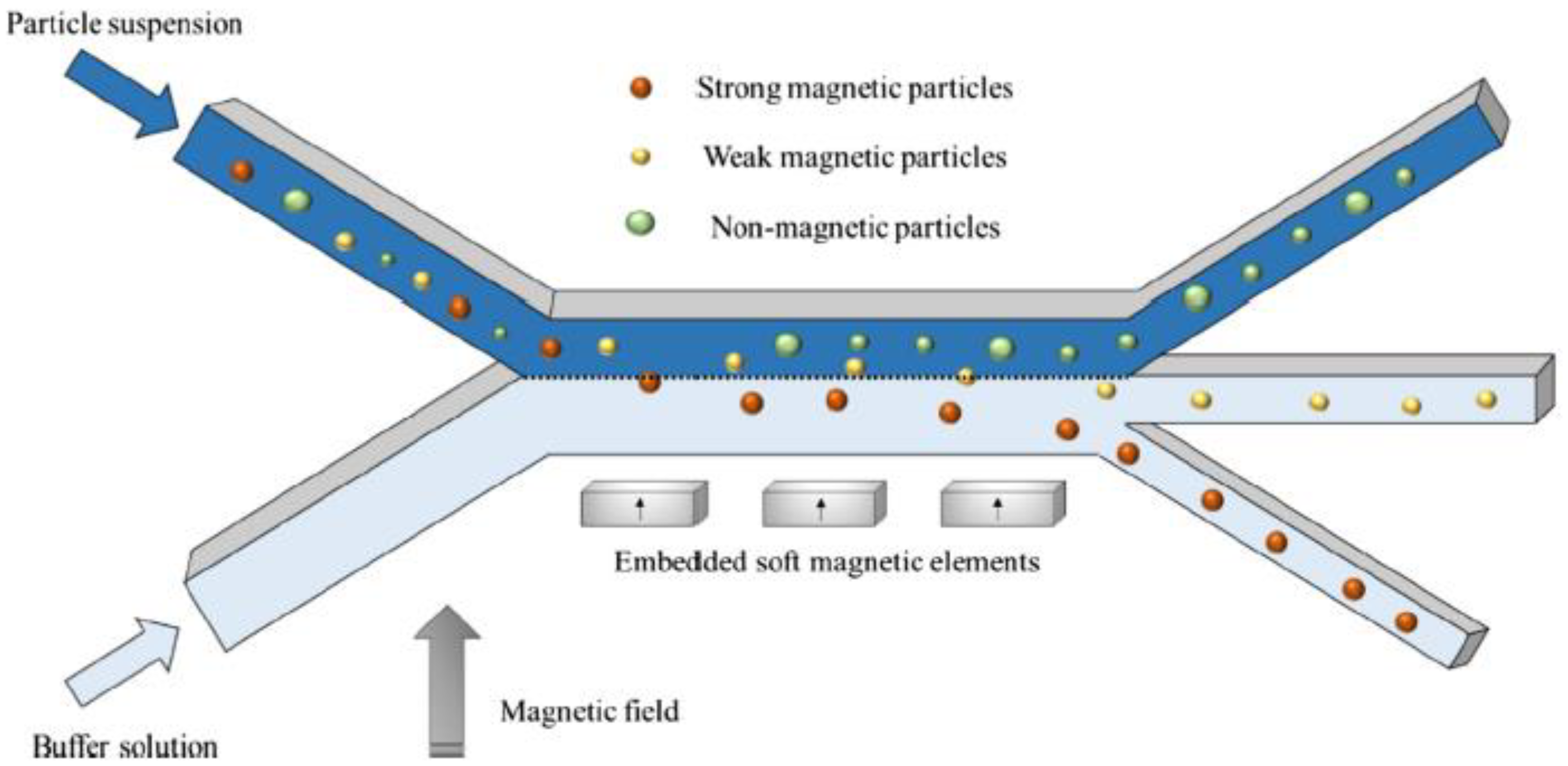
Finally, implementing magnetic functionality into the microfluidic devices can be done by several means. The most common approach is to place magnetic elements in the vicinity of the microchannel [79]. Such elements produce a magnetic field gradient inside the channel, which exerts an attraction force on the labeled biomaterials or the magnetic beads as they flow through the channel (Figure 2). Microfluidic devices engineered with permanent magnets enable on-chip manipulation of magnetically labeled biomaterials which requires no power consumption [31]. Other approaches using electromagnets have been developed as well, but their disadvantages are the required circuitry and the possible temperature raise due to the Joule heating, which may pose concerns if the biological material is temperature sensitive [79].

Electric Forces

Electric fields can separate particles via electrophoresis (EP) and dielectrophoresis (DEP). EP is not covered in this work, as it is not generally applied for separating particles and cells since it relies on the separation of charged materials under the influence of an electric field [45]. DEP is the most common technique used to separate particles and cells because it does not require the material to be electrically charged [45]. Thus, we will review only the simulation studies that describe particle and cell DEP.
Analogously to magnetophoresis, DEP induces a cell/particle movement in a nonuniform electric field based on the dielectric properties (electrical conductivity and permittivity) of the cell and the surrounding medium [45]. The exerted force from the nonuniform electric field on a dielectric material (with zero net charge) polarizes the particles to generate corresponding induced charges on the surface (Figure 3), which generates, in turn, dipole moments, and due to the force, the ends of the positive and negative charges are uneven [50]. This induced dipole in a nonuniform electric field causes the particle to be pulled electrostatically along the electric field gradient when it approaches the gap between the electrodes [26,45].
More specifically, at material interfaces, this polarization is revealed by the formation of macroscopic multipoles. If the excitatory field is inhomogeneous, the Coulomb forces acting on each half of the particles are unequal, which causes a net dielectrophoretic force acting on the particle, as seen in Figure 3 [61]. The magnitude and direction of the DEP force can be obtained by computing the cell’s or particle’s effective dipole moment [44]. The DEP force acting on the imposed electric field of an induced dipole is given by [9,44,47,80]:
F DEP = 2 π ε m r 3 Re [ K ( ω ) ] E 2
where
K ( ω ) = [ p * m * p * + 2 m * ]
where εm is the permittivity of the medium, K(ω) is the Clausius–Mossotti factor that depends on the angular frequency of the applied field ω, E is the electric field, and p * and m * are the complex permittivities of the particle/cell and the medium, which are a function of the permittivity and conductivity of the material and the angular frequency of the applied electric field ω [15,80]. Either Direct or Alternating Current (DC or AC, respectively) sources can be employed to create a nonuniform electric field [46], but AC is chosen in most of the studies due to the low input voltage requirements, which avoids Joule heating effects and cell/particle damage [47,54].
The value of Re[K(ω)] varies in a range from −0.5 to 1 [26]. According to it, DEP is frequently classified into positive DEP (pDEP) if Re[K(ω)] > 0 and negative DEP (nDEP) if Re[K(ω)] < 0. As a result, the particles forced by pDEP response are guided toward the location of the high electric field strength (around the edges of the electrodes). In contrast, the particles forced by nDEP response are moved to the low electric gradients (away from the electrodes). In other words, if the polarizability of the particle is greater than that of the liquid, it makes the particle move towards the region with the highest electric field gradient [45]. For many materials, the real part of K(ω) is negative over a wider range of low to very high frequencies, and it is positive at very low frequencies. The frequency at which the material experiences neither p-DEP nor n-DEP is the crossover frequency [47]. This is a specific frequency at which the intrinsic properties of particles and cells can be defined [15]. For the separation or isolation of cells and biological material, it is desirable to employ nDEP so that the material is directed towards the low electric field region to minimize unwanted transfection and disruption of cell structure/membrane [11]. It should also be noted that while the electric field induces DEP forces on the particles, it also induces an electro-osmotic and electrothermal flow that might affect the separation [45].
The DEP devices consist of two main parts integrated into a substrate: the electrodes, which can be of different types and generate the nonuniform electric field inside the microchannel, and the microchannel itself, which contains the particle/cell suspension. Planar and three-dimensional (3D) electrode structures are commonly used for these applications. 3D electrodes are fabricated on the top and bottom, or sidewalls of microfluidic channels, whereas planar electrodes are commonly embedded on the bottom of microfluidic channels [15].
Usually, the separation of particles can be easily modeled once their properties are characterized. On the contrary, cells generally have a relatively complex internal structure that can affect their dielectric properties, and equivalent cells of different structures produce different results. Some can be directly equivalent to a solid sphere, and some need to establish an equivalent model for biological particles. Among them, the concentric spherical model is more common [9,15,50]. With this model, the cells are assumed to possess two concentric layers of various electric and dielectric properties [15]. In any case, the electric fields can be effectively used to analyze and separate particles and cells based on their electric properties. Indeed, DE properties of cells have been linked to changes in plasma membrane capacitance, permeability, and change in Ca+ and K+ ion levels in the cytoplasm, which can be related to their response to different drugs, infection, even cancer cell aggressiveness, etc.; these result in plasma membrane and cytoplasm electrical conductivity changes [44,80].

Acoustic Forces

Acoustic forces originate from the scattering of imposed ultrasound waves from objects or particles suspended in a fluid. The scattering of waves occurs in a fluid when particles suspended in it are exposed to an acoustic field. Due to this scattering, second-order forces arise, known as acoustic radiation forces. The radiation forces are time-averaged forces that can effectively transport the suspended particles. The direction of such motion of a particle depends upon its properties and the surrounding fluid medium (density and compressibility) [14,16]. When such force on particles overcomes the viscous drag, gravity, and other forces, particles may exhibit acoustophoretic motion irrespective of their inherent electrical or magnetic properties [16]. Particles with varying sizes or physical parameters resulting in different acoustic properties will be exposed to different acoustic radiation pressures. They will move to specific regions of the channel (pressure nodes or antinodes) at different intervals, resulting in distinct identifiers for separation and diagnosis [2,71].
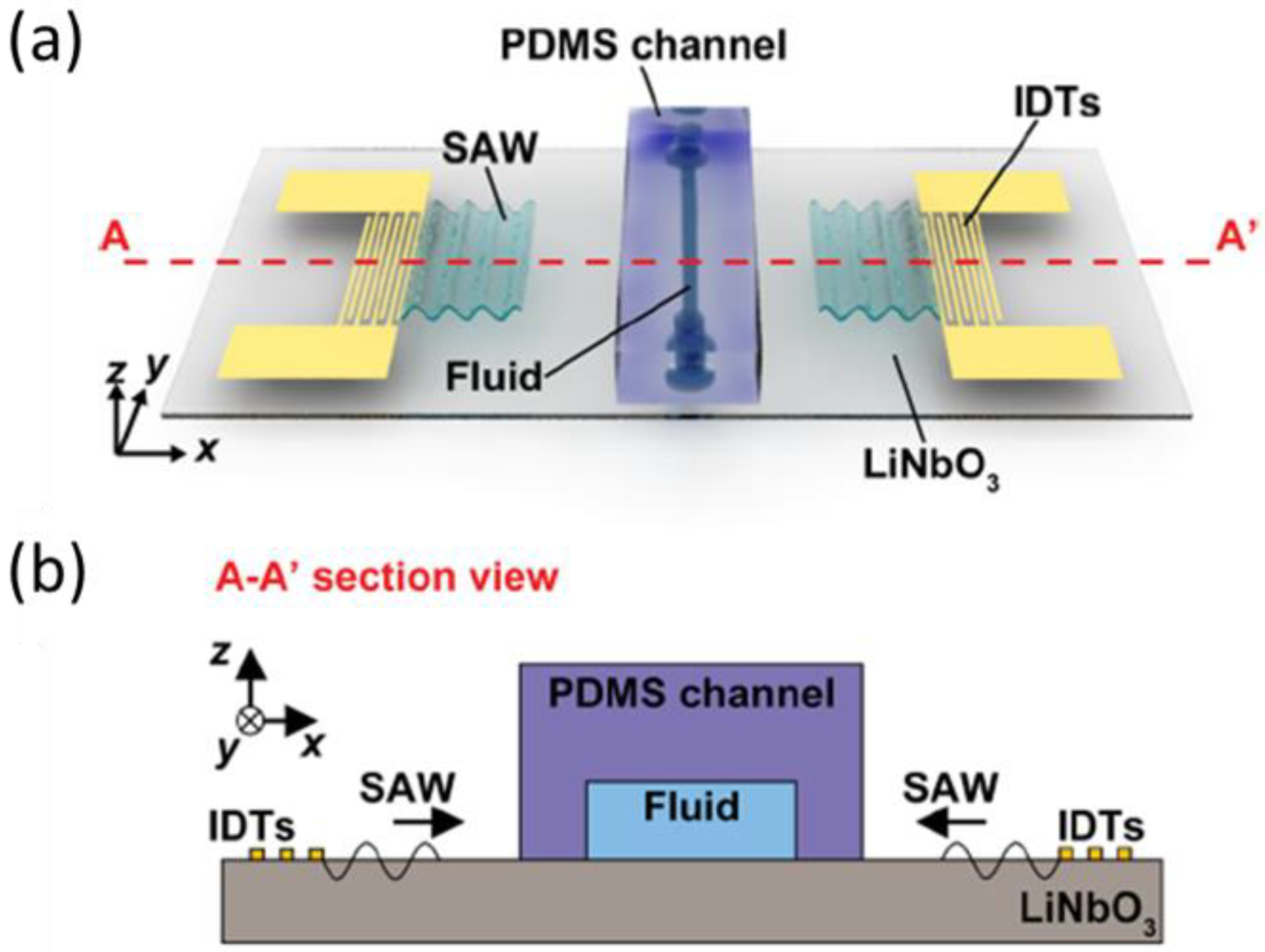
An acoustic cell sorter consists of a piezoelectric substrate with interdigital transducers (IDTs) to generate surface acoustic waves (SAWs) and a microfluidic channel bonded to the substrate, as seen in Figure 4. SAWs are mechanical waves that primarily propagate upon the surface of an elastic material. These waves consist of a longitudinal compression motion coupled with a transversal shear motion [8]. It should be noted that bulk acoustic wave devices generated by substrate-bonded bulk transducers are outside the scope of this work due to their unsuitability for microfluidic devices and high operating frequency and energy requirements [8,19,75].
When a surface standing acoustic wave (SSAW) is applied between the opposite walls of the channel (which act as reflectors) by exciting the piezoelectric elements, a harmonic standing pressure field is formed in the fluid. In most cases, a half-wavelength standing wave is usually generated in the lateral direction of the fluid channel (i.e., perpendicular to the continuous flow direction) with a pressure node in the channel center and pressure antinodes located at the channel walls [24]. Besides SSAW techniques, there exist also traveling surface acoustic waves (TSAW) sorting approaches, which change the pressure of the fluid and drive the particles to move to the other side. However, TSAW devices are not as common as SSAW devices. More specifically, TSAWs are waves that propagate in one direction and push the dispersed particles/cells in the direction of propagation. In contrast, SSAWs are formed in the volume of the microchannel as a result of the superposition of two traveling waves, which move towards each other and have some phase shift [75]. The design and electrical signal applied to IDTs completely defines the frequency, amplitude, and orientation of the generated acoustic waves; however, the microchannel dimensions and layout, together with its material and liquid phase composition, will affect the acoustic wave propagation and fluid-particle interaction [75].
The acoustic radiation force Frad exerted on compressible particles/cells suspended in an inviscid fluid arising from an acoustic field can be calculated using the Gorkov’s potential approach as [5,14,16]:
F rad = U rad
where
U rad = V p [ f 1 1 2 k f p in 2 f 2 3 4 ρ f v in 2 ] ,  
f 1 = 1 k p k f ,  
f 2 = 2 ( ρ p ρ f 1 ) ( 2 ρ p ρ f + 1 )
where Urad is the potential in the acoustic domain, pin and vin are the first-order pressure and velocity of the incoming acoustic waves. The density and compressibility of the fluid and the particles are denoted by ρf, ρp, kf, and kp, respectively, and the factors f1 and f2 are the dimensionless scattering coefficients [5,16]. In general, for most applications, compared to smaller and less dense particles, larger and denser particles move faster towards the pressure nodes for higher acoustic radiation forces. Thus microparticles of different physical properties will end up in different lateral positions and be separated into different outlets at the end of the acoustic separation channel [24].
This formulation is valid when inviscid fluids and spherical particles (smaller than the acoustic field wavelength λ) are considered. In most cases, inviscid fluids are assumed even though viscous fluids are employed [1]. For cases where this assumption cannot be adopted, a corrected expression for f2 must be considered (see Ref. [16]).
Regarding the particle or cell movement, the acoustophoretic contrast factor is calculated to determine the direction of the force. This is given as:
ϕ ( k , ρ ) = [ f 1 3 + f 2 2 ] = 1 3 [ 5 ρ p ρ f 2 2 ρ p ρ f + 1 k p k f ]
If the material has a ϕ value higher than 0, the direction of the force is towards the nodes of the standing pressure wave (minima Urad), whereas a negative ϕ implies that the force acts towards the pressure antinodes.

2.3. Numerical Methods

Different methods can be used to solve the partial differential equations, such as the force equations and particle/cell migration equation within the device. In this section, the Finite Element Method (FEM) and Finite Volume Method (FVM) are introduced since they are the most common methods and the ones integrated into commercial simulation software. The exact details of how the constituent equations are solved for each method are beyond the scope of this article. Still, a general overview is provided, along with the advantages and disadvantages of each method.

2.3.1. Finite Element Method

For the FEM, the computational domain is subdivided into smaller sections, i.e., elements usually in the shape of a triangle or tetrahedron. The unknown variable/parameter is then solved for each element so that the differential equation is satisfied at each boundary. Some of the core advantages of the FEM method are its ability to handle domains that include complex geometrical features, due to the use of body-fitted meshing, and its accuracy since higher-order approximations are used [83]. The FEM method is applied in various commercially available computational software packages. For example, COMSOL Multiphysics (www.comsol.com accessed on 1 June 2022) is a simulation platform that provides fully coupled multiphysics and single-physics modeling capabilities, which is based on the FEM to realize the simulation of real physical phenomena by solving partial differential equations (groups) [50]. It is applied to the research and engineering calculation of various disciplines, simulating the physical processes of science and engineering. It represents one of the most common numerical analysis software packages employed in optimizing particle and cell separation in microchannels.

2.3.2. Finite Volume Method

The FVM is a subsection of the finite differences method (FDM) commonly used in many commercial CFD software packages. In FVM, the domain is split into rectangular volumes, i.e., cells with their edges aligned to the coordinate system used. The solved quantities are stored in the center of each volume for non-vectors (e.g., temperature) and at the edges of each volume for vectors (e.g., velocity). Some of the advantages of the FVM are its computational simplicity which makes it computationally possible to solve for large domains and ease of implementation [83]. There are a plethora of commercially available software packages that are based on the FVM, such as PHOENICS (www.cham.co.uk accessed on 1 June 2022), ANSYS Fluent (www.ansys.com accessed on 1 June 2022), FLOW-3D (www.flow3d.com accessed on 1 June 2022), and STAR-CCM+ (https://www.plm.automation.siemens.com/global/en/products/simcenter/STAR-CCM.html accessed on 1 June 2022). Most notably, OpenFOAM, an open-source software, uses the FVM to solve partial differential equations [58]. The software packages mentioned above have also been used to model particle separation in microfluidics.

2.3.3. Mesh Dependency Analysis

Independent of the software employed, it is required to assess the accuracy of the numerical results by performing a mesh dependency study. That, in principle, consists of running a given problem with a progressively refined mesh, i.e., gradually increasing the number of elements or cells until the difference between the results of the mesh independent domain and the immediately finer domain is less than a given value. Usually, errors below 5% are considered, but some applications might require more accurate simulations, and finer meshes are employed to ensure that the error stays below 1% [70]. The mesh dependency study must be performed as the last step of problem setup before proceeding to the parametric analysis.

3. Recent Simulation Studies

This section reviews the most recent simulation studies on the active separation of particles and cells inside microchannels. We start with magnetophoresis studies, followed by dielectrophoresis, and end with acoustophoresis.

3.1. Magnetic Separation

Table 1 presents the main simulation studies performed in the last 5 years on the microfluidic separation of particles and cells using magnetic means. Most of these works used a Lagrangian-Eulerian (particle-based) model, but other approaches have been explored, too [27], and COMSOL Multiphysics is the preferred platform to simulate the process. As seen in the table, one of the main challenges of magnetophoretic microfluidic devices is their typically small volume capacity, which implies the use of relatively low flow rates. Nevertheless, numerical methods can be employed to estimate the device performance and optimize the working conditions in advance of fabrication so that high magnetic field gradients and flow rates are achieved. For example, Castillo-Torres et al. [29], using a combination of modeling and experimental techniques, designed a microfluidic device able to separate bacteria magnetically conjugated to magnetic disks at flow rates higher than 100 µL/s using a magnet array. They achieved around 94% efficiency in the bacterial detection/separation, analyzing 100 mL of water samples in less than 15 min. Moreover, Golozar et al. modeled and optimized a magnetophoretic chip to isolate cells conjugated to magnetic beads [31]. Their design consisted of a continuous-flow microfluidic platform that contained locally engineered magnetic field gradients able to separate different cells previously conjugated to magnetic beads at flow rates up to 200 mL/h. The simulations were used to predict the trajectory and capturing region of the cells and to analyze the effect of the magnetic bead size, cell size, number of beads per cell, and flow rate on the separation performance.
On the other hand, Civelekoglu et al. [36], with the aid of numerical simulations, introduced a cytometry technique that computed the surface expression of immunomagnetically labeled cells by electrically tracking their trajectory under a magnetic field gradient on a microfluidic chip with a throughput of >500 cells/min. More specifically, immunomagnetically labeled cells were deflected under a magnetic field gradient according to their magnetic load (or surface expression) and detected at the different outlets of the device (Figure 5). Their device allowed direct expression profiling of target subpopulations from non-purified samples. It was demonstrated via application to measure epithelial cell adhesion molecule (EpCAM) expression on human breast cancer cells.
The separation of magnetic particles from fluids within microchannels has also been addressed for its implementation within nanoparticle synthesis procedures. The cleaning process of synthesized nanoparticles is usually performed by multi-step procedures involving filtrations, centrifugations, or manually washing with the help of a powerful magnet; these procedures are not only time-consuming but also inefficient as a large number of nanoparticles are often lost, and traces of solvents, surfactants, or byproducts remain after the process [37]. To overcome these limitations, Cardoso et al. [37] used a microfluidic device for the automated and continuous cleaning and separation of the material. Using numerical simulation and experimental testing, their microfluidic device cleaned and recovered more than 99% of iron oxide nanoparticles, obtaining a higher recovery than manual procedures (94%). Other studies have also focused on the sorting of the nanoparticles after synthesis to obtain fractions uniform in size [43]. Moreover, numerical simulation has also been employed to optimize devices where negative magnetophoresis occurs. Indeed, Munaz et al. [38] designed a device where different diamagnetic particles suspended in a ferrofluid are separated via negative magnetophoresis, as seen in Table 1. The authors used a numerical model to optimize the magnet array configuration and the effect of flow rate ratios, and the concentration distribution of ferrofluid in the device.
It should be noted that numerical models have also been applied to optimize the separation of cells/biomolecules based on their intrinsic magnetization (without using magnetic beads as labels). The separation of intrinsically magnetic (paramagnetic) cells or biomaterial is more challenging because of the orders of magnitude weaker magnetizations observed in these materials (much weaker than what can typically be achieved in immunomagnetically labeled cells) [34,84]. For example, Sun et al. [34] employed a separation system called magnetic deposition microscopy (MDM) to not only separate cells, but to deposit cells in specific locations on slides for further microscopic analysis based on their intrinsic magnetizations. These authors characterized the MDM system using finite element and computational fluid mechanics software and predicted the separation performance of magnetic spores (Bacillus spores). Analogously, Kasetsirikul et al. [41] designed a device to separate malaria-infected RBCs, which show paramagnetism and suffer positive magnetophoresis when exposed to magnetic fields. Their numerical simulations suggest that the infected RBCs could be separated from healthy RBCs in a continuous flow using magnet arrays.
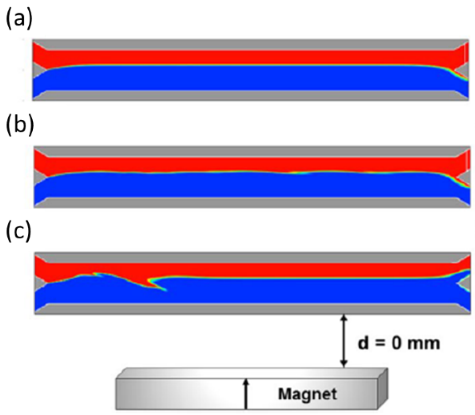
Numerical models have also been used to analyze the mixing of co-flowing fluids while magnetophoresis takes place. Gomez-Pastora et al. [32] employed a Lagrangian computational model for designing continuous-flow magnetophoretic microsystems for blood detoxification, assuring complete particle/biomaterial capture without compromising the quality of the blood (avoiding diffusion or loss of blood). The model was used to study the particle trajectory, the flow pattern and mass transfer between streams, and the analysis of multiple variables and parameters (flow rates, beads and magnets dimensions, fluid viscosities, etc.) was numerically and experimentally performed. In a later study [33], these authors provided a detailed analysis of the bead motion and its effect on fluid flow while magnetophoresis takes place (Figure 6). Different scenarios were modeled and compared: (i) one-way coupling wherein momentum is transferred from the fluid to the beads, which are treated as point particles, (ii) two-way coupling wherein the beads are treated as point particles, and momentum is transferred from the bead to the fluid and vice versa, and (iii) two-way coupling taking into account the effects of bead volume in the fluid displacement. It was demonstrated that although there is little difference in the bead trajectories for the three scenarios, there is significant variation in the flow fields, especially when high magnetic forces are applied to the beads. Therefore, employing an accurate full flow-focused model that considers the effects of the bead motion and volume on the flow field when high magnetic forces are employed is recommended; however, when the beads are subjected to medium or low magnetic forces, computationally inexpensive models can be safely employed. Even though the experimental validation was not performed, similar studies proved that the fluid flow is perturbated under high magnetic fields and gradients when performing the continuous-flow magnetophoresis of ferrofluid droplets [85].

3.2. Dielectrophoretic Separation

The use of dielectrophoretic forces is very popular and one of the most widely used in the microfluidic separation of micron-sized materials. Table 2 presents the numerical studies published in the last 5 years dealing with the modeling and optimization of DEP in microdevices. As can be seen from the table, COMSOL Multiphysics is the preferred software to perform these studies. This software combines different modules (the laminar flow module, AC/DC module, and particle trajectory tracking module) valid to simulate the separation process [50,52]. More specifically, the laminar flow module is used to calculate the distribution of the flow field in the main channel; the AC/DC module is used to calculate the distribution of the electric field in the main channel; the particle trajectory tracking module coupling the influence of the flow field and electric field on the particle trajectory is used to calculate the trajectory of the particles in the channel [50]. These models have been experimentally validated in most of the studies, and good agreement between experiments and simulations has been achieved [49].
The reported simulation studies have optimized the electrode configuration, applied electric frequency, voltage amplitude, fluid flow rate, conductivity, etc. [9,26,45,46]. It can be seen in Table 2 that most of the studies involving the separation of cells deal with blood separation and are performed using nDEP. For example, Nguyen et al. [26] carried out theoretical calculations and simulations to define the favorable parameters in the electric field operation of the microchip before its application to separate circulating tumor cells (CTCs) from RBCs, which is one of the most crucial procedures for subsequent detection and treatment of cancer.
Similarly, Zhang and Chen performed a numerical study to find the optimum conditions (medium parameters, voltage, and frequency) for the DEP separation of blood cells [9]. In a different study [54], CTCs were separated from RBCs via DEP using microchannels with flow obstacles. A finite element simulation was conducted to predict the cell trajectories and revealed that the device with rectangular obstacles showed the best performance, achieving 100% separation efficiency and purity for cancerous cells in the specific outlets [54]. On the other hand, the optimization of electrode location and operating voltages were numerically performed by Kumar et al. [46]. These authors simulated several conditions and voltages for the separation of bacteria from blood cells and achieved effective separation of cells smaller than 1 µm using voltages below 20 V. It should be noted that high voltages are required to separate small particles via DEP. However, operating at higher voltages could lead to localized Joule heating, which may induce changes in conductivity and permittivity of the particles near the electrodes, and may create turbulence due to electrothermal fluid flow [46]. Furthermore, PDMS and polymethyl methacrylate (PMMA), such as deformable substrates used for microchannel manufacturing, may be affected by the induced heating at high voltages [46]. Thus, to overcome such electro thermal problems, optimization of electrode location and operating voltages need to be performed, and numerical models are powerful techniques to carry out such studies in advance of fabrication.
DEP has also been studied for the separation of particles [3,49,52]. Tirapu-Azpiroz et al. [49], using a FEM solver, simulated the dielectrophoretic separation of polystyrene (PE) beads using a capillary-driven microdevice. More specifically, the model was used to optimize the electrode layout and voltage configuration. These authors demonstrated the separation of 10 μm and 5 μm beads experimentally, with ~98% efficiency. Chen et al. [52] employed three-dimensional (3D) electrodes composed of Ag powder (particle size of 10 nm) and PDMS for the separation of PE particles via DEP. Through theoretical calculations, numerical simulations, and experimental verification, the role of their new composite 3D microelectrodes was tested for the separation of 5, 10, and 20 µm PE beads.
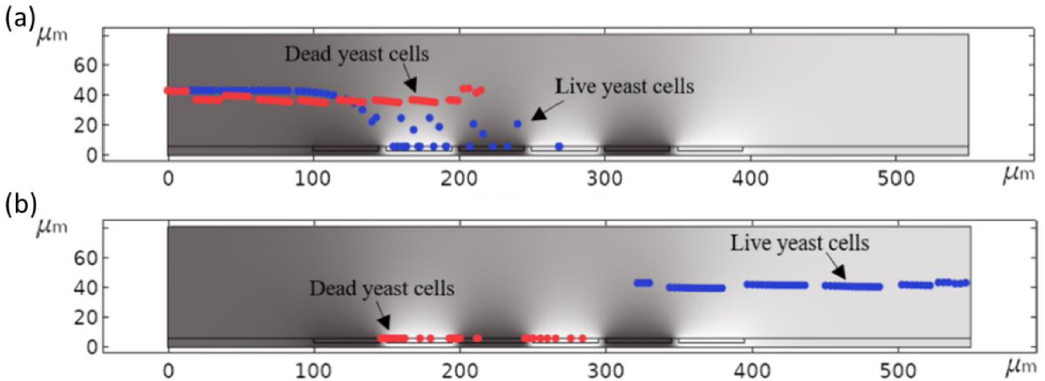
Moreover, electric fields have been used to analyze different particles and cells according to their dielectric signatures. Differences in DEP responses of individual cells are based on differences in their structural and dielectric properties that might be linked to different intracellular processes. Fikar et al. [44] simulated and experimentally employed a novel method called distributed dielectrophoretic cytometry (2DEP cytometry) to measure dielectrophoresis forces acting on live cells in a microfluidic device. This method was employed to quantify the DE signatures of immortalized myelogenous leukemia cell lines. Analogously, Ettehad et al. [15] developed a microfluidic device that enabled the manipulation and characterization of live and dead yeast cells using dielectrophoretic forces. This is possible because of the different size and dielectric properties between live and dead cells. These authors, using FEM modeling, optimized the electrode configuration of the devices and selected the optimum operating conditions. The final device and their experimental approach successfully demonstrated the feasibility of the technology to trap live yeast cells inside the device and purify them from dead cells (Figure 7).
Finally, it should be noted that the nonuniform electric field can be generated using an array of electrodes or an array of insulating posts. Traditionally, DEP studies employed different microelectrode configurations, causing a nonuniform electrical field distribution inside the microchip. Advantages include a low voltage application for operating, but disadvantages exist, such as the need for complex microfabrication techniques and loss of functionality due to fouling [61]. The use of insulator-based DEP can overcome some of these disadvantages and has been the subject of numerical studies. For example, Aghaamoo et al. [61] used a numerical model to investigate the performance of different design aspects of insulating posts (pots geometry, electrode setups) and optimized the working conditions for the separation of CTCs from white blood cells (WBCs).

3.3. Acoustophoretic Separation

Different studies have addressed the simulation of particle and cell acoustophoretic separation with high accuracy. Table 3 presents the numerical studies that have been performed in the last 5 years to optimize the particle and cell acoustophoretic separation. As occurred with DEP, COMSOL Multiphysics is the software preferred since it integrates several modules that allow the accurate simulation of the process (pressure acoustics, laminar flow, particle tracing, etc.) [1,8,76]. More specifically, FEM codes have been used to optimize several variables and parameters that affect the process, such as the applied voltage or the effect of the IDTs location (distance from the channel and angle), number of IDT fingers, microchannel’s height, the main flow velocity, and flow rate, etc. [8,19,71,74]. As seen in Table 3, the separation of cells via acoustophoresis, mostly blood cells, has been successfully modeled and optimized using numerical models.
Moreover, acoustophoresis has been used not only to manipulate cells within microchannels but also to capture them in specific regions covered by antibodies. For example, Gupta et al. [16] placed antibody-coated polystyrene layers in the nodal regions of an acoustic field to capture infected RBCs with malaria parasites from plasma (the fluid condition was considered stationary to avoid cell lysis or cell-antibody bonds rupture due to shear stress). These layers have acoustic properties quite similar to the fluids involved (i.e., they are “acoustically transparent” as they do not impede wave propagation) and are biocompatible. Their device allowed bidirectional migration of the suspended cells to the biofunctionalized surfaces. Thus, simultaneously capturing infected erythrocytes on both layers could be feasible. The authors made use of FEM to model the pressure field as well as the motion of erythrocytes under the influence of acoustic radiation, drag, and gravitational forces. Based on the simulations and the trajectories of the erythrocytes, the location of the functionalized surface could be calculated before the fabrication of the device.
Furthermore, numerical models can also be implemented to account for the effect of channel elements (materials and orientations) in the SAW path. The total internal reflection (TIR) at the channel–fluid interface affects the entire fluid domain, where diffractive interference patterns arise from the imposition of a channel-bounded traveling SAW. TIR occurs when a wavefront propagates between domains with different sound speeds. It can cause undesired particle aggregation at channel walls and might require a complex design of channel or addition of sheath flows if not taken into account [72]. Since the walls are an essential component of these devices, it is important to couple particle actuation to the channel geometry/material rather than just the underlying SAW, allowing for highly localized patterning and focusing activities that can be incorporated by shaping the channel features [1,5]. For example, Richard et al. [1] used a numerical FEM model to study the effect of the wall material on the process (in this case, SU-8, which has a higher acoustic impedance than that of water, and this results in a more complex acoustic behavior than regular PDMS channels due to increased reflections at the fluid-solid interface). After obtaining the numerical solution for the pressure field, the authors optimized the separation of RBCs from platelets in such a device (Figure 8).
Baek et al. performed a series of simulations accounting not only for the particle properties but also its surrounding component parameters [72]. To this end, they investigated the role played by the sound speed mismatch between the fluid and the channel in an SSAW device. More specifically, they determined the positions of patterned particles by analyzing the effects of the acoustic properties of the channel and the fluid on the pressure field, acoustic streaming field, and particle destination through both computational and experimental techniques [72]. On the other hand, Collins et al. [5] demonstrated (using an analytical model though) how curved and straight PDMS channel interfaces affect particle separation and tried to develop a comprehensive theory of channel wall interactions to examine the full range of channel wall orientations.
Finally, it should be noted that most theoretical/numerical studies on the acoustophoretic motion of a particle caused by acoustophoresis assume forces applied on small rigid particles (particle size <<< acoustic wavelength) suspended within an ideal fluid [70]. A few works have addressed the compressibility of the particle and used formulations beyond the ideal fluid assumption [70]. Studies dealing with the simulation of bigger particles (particle size ≈ wavelength) are scarce. For example, Samandari et al. [70] used a FEM simulation approach to simulate with high resolution the acoustophoresis of particles at high frequencies in a microchannel. More specifically, they used a FEM model to amend analytical calculations of the acoustic radiation force arising from an imposed standing ultrasound field. To calculate the force and the resultant deformation-induced on the particles, they implemented a solid acoustic interaction (ASI) approach. A particle-tracking scheme was used to obtain the separation efficiency and the patterning of the particles under relevant conditions. They demonstrated a significant mismatch between the force obtained from the ASI approach and previous analytical predictions that considered small particle assumptions when working at high manipulation frequencies due to both different ARF values and the variation in force maps in multidirectional wave propagation.

4. Conclusions and Further Directions

In this work, we have summarized the numerical modeling of the active separation of particles and cells within microchannels. Specifically, separation using magnetophoretic, dielectrophoretic, and acoustophoretic forces has been analyzed. First, we have established the different approaches used to calculate the particle/cell migration inside the device, emphasizing the Lagrangian approach, where the particle trajectory is calculated as a function of the external forces acting on the material. The formulation of the drag force, gravitational force, and the active forces responsible for the separation are also formulated. For active forces, equations to calculate the particle movement in magnetophoresis, dielectrophoresis, and acoustophoresis are developed. Different methods to solve the equations are also introduced, such as the FEM and FVM, and the importance of performing a mesh dependency study is highlighted. Finally, the different studies dealing with the numerical modeling of the process are presented. We demonstrated the effectiveness of numerical modeling in optimizing the different variables and parameters that affect the process in advance of fabrication. Also, we reviewed the models developed in the different studies, the software employed, and the conditions simulated to offer the readers different guidelines about the capabilities of the CFD software. Nevertheless, there are different directions where improvement can be done.
On the one hand, and as seen in the sections above, COMSOL Multiphysics® (versions 5 and above, founded by Dr. Svante Littmarck and Farhad Saeidi, 100 District Avenue, Burlington, MA 01903, USA)is the preferred software to simulate the process. This multi-purpose software package is user-friendly and contains the modules required to simulate the separation. It is specifically designed to solve multi-applied physics and engineering phenomena as a simulation tool for electrical, mechanical, fluid flow, chemical, and other applications within one package [39,40]. Other software platforms have also been used, but they require the implementation of the fields and forces by the user using customized codes, which limits their use to more experienced CFD engineers. For example, DEP has been modeled using Ansys Fluent, but a User Defined Function (UDF) needs to be written in C++ and integrated into the Ansys Workbench to solve for the electric field and electric potential distribution within the computational domain and also to calculate the DEP forces at any location depending on the fields and particle/cell parameters [63]. Analogously, for modeling magnetophoresis, some authors have used Ansys Fluent or Flow-3D [32,33], which require the implementation of the magnetic field, gradient, and force by using external subroutines linked to the main solver. Future efforts should be directed towards implementing modules that allow the calculation of electric/magnetic fields and gradients and the calculation of forces acting on the particulate material.
On the other hand, most of the studies have neglected particle-particle and particle-fluid interactions. It should be noted that a precise calculation of the interparticle effects as well as the effects that the particles have on the fluid field might be required for some applications. For example, magnetic dipole-dipole interactions or electrostatic interactions between particulate material could be beneficial for the separation process as they may speed up the aggregation of the material and/or magnify the force acting on it [82]. On the other hand, modifying the flow patterns as the material is separated might have detrimental consequences for the process if mixing is undesired and could underestimate the value of the force required for separation [33]. These effects are not easily implemented in commercial CFD software programs. Therefore, future work should focus on improving the accuracy of these models to apply them to the processes where particle-particle and particle-fluid effects cannot be neglected.
It should also be noted that although the experimental validation is carried out in most studies, it is not properly quantified. The difference between the experimental and theoretical results (for example, the difference in particle position values or the particle recovery) is only presented in a few works. Thus, future efforts should also be directed toward quantifying the accuracy of the theoretical models by performing proper experimentation.
In conclusion, the potential of CFD software to accurately model microscopic and macroscopic systems while integrating a plethora of different physical models into one simulation, and along with advances in computer hardware and algorithms, only favor numerical modeling. We believe that the future of this technology is bright, and should prove paramount in the development and optimization of the design of novel cell and particle separation medical devices.

Author Contributions

Conceptualization, I.H.K.; formal analysis, I.H.K. and J.G.-P.; funding acquisition, J.G.-P.; investigation, I.H.K. and J.G.-P.; methodology, J.G.-P.; project administration, J.G.-P.; supervision, J.G.-P.; writing—original draft, I.H.K. and J.G.-P.; writing—review and editing, J.G.-P. All authors have read and agreed to the published version of the manuscript.

Funding

This research received no external funding.

Institutional Review Board Statement

Not applicable.

Informed Consent Statement

Not applicable.

Data Availability Statement

Not applicable.

Conflicts of Interest

The authors declare no conflict of interest. The funders had no role in the design of the study; in the collection, analyses, or interpretation of data; in the writing of the manuscript, or in the decision to publish the results.

References

  1. Richard, C.; Fakhfouri, A.; Colditz, M.; Striggow, F.; Kronstein-Wiedemann, R.; Tonn, T.; Medina-Sánchez, M.; Schmidt, O.G.; Gemming, T.; Winkler, A. Blood platelet enrichment in mass-producible surface acoustic wave (SAW) driven microfluidic chips. Lab. Chip 2019, 19, 4043. [Google Scholar] [CrossRef] [PubMed] [Green Version]
  2. Yousuff, C.M.; Pavithra devi, E.; Swetha, C.; Ramya, R. Acoustic Based Separation of Blood Cells Using Microfluidic Device. In 2021 Seventh International Conference on Bio Signals, Images, and Instrumentation (ICBSII); IEEE: Piscataway, NJ, USA, 2021; pp. 1–5. [Google Scholar] [CrossRef]
  3. Rahman, M.R.U.; Kwak, T.J.; Woehl, J.C.; Chang, W.J. Quantitative analysis of the three-dimensional trap stiffness of a dielectrophoretic corral trap. Electrophoresis 2021, 42, 644–655. [Google Scholar] [CrossRef] [PubMed]
  4. Gómez-Pastora, J.; Bringas, E.; Lázaro-Díez, M.; Ramos-Vivas, J.; Ortiz, I. The reverse of controlled release: Controlled sequestration of species and biotoxins into nanoparticles (NPs). In Drug Delivery Systems; Stroeve, P., Mahmoudi, M., Eds.; World Scientific: Hackensack, NJ, USA, 2017; pp. 207–244. [Google Scholar]
  5. Collins, D.J.; O’Rorke, R.; Neild, A.; Han, J.; Ai, Y. Acoustic fields and microfluidic patterning around embedded micro-structures subject to surface acoustic waves. Soft Matter 2019, 15, 8691. [Google Scholar] [CrossRef]
  6. González Fernández, C.; Gómez-Pastora, J.; Basauri, A.; Fallanza, M.; Bringas, E.; Chalmers, J.J.; Ortiz, I. Continuous-flow separation of magnetic particles from biofluids: How does the microdevice geometry determine the separation performance? Sensors 2020, 20, 3030. [Google Scholar] [CrossRef] [PubMed]
  7. Weigand, M.; Gómez-Pastora, J.; Palmer, A.; Zborowski, M.; Desai, P.; Chalmers, J. Continuous-Flow Magnetic Fractionation of Red Blood Cells Based on Hemoglobin Content and Oxygen Saturation—Clinical Blood Supply Implications and Sickle Cell Anemia Treatment. Processes 2022, 10, 927. [Google Scholar] [CrossRef]
  8. Taatizadeh, E.; Dalili, A.; Rellstab-Sanchez, P.I.; Tahmooressi, H.; Ravishankara, A.; Tasnim, N.; Najjaran, H.; Li, I.T.S.; Hoorfar, M. Micron-sized particle separation with standing surface acoustic wave—Experimental and numerical approaches. Ultrason. Sonochem. 2021, 76, 105651. [Google Scholar] [CrossRef]
  9. Zhang, Y.; Chen, X. Blood cells separation microfluidic chip based on dielectrophoretic force. J. Braz. Soc. Mech. Sci. Eng. 2020, 42, 206. [Google Scholar] [CrossRef]
  10. Kim, J.; Gómez-Pastora, J.; Weigand, M.; Potgieter, M.; Walters, N.A.; Reátegui, E.; Palmer, A.F.; Yazer, M.; Zborowski, M.; Chalmers, J.J. A Subpopulation of Monocytes in Normal Human Blood Has Significant Magnetic Susceptibility: Quantification and Potential Implications. Cytometry A 2019, 95, 478–487. [Google Scholar] [CrossRef]
  11. Rahman, M.R.U.; Kwak, T.J.; Woehl, J.C.; Chang, W.J. Characterization of stiffness of micro-particle trapped in dielectrophoretic-microfluidic device. In 2020 2nd International Conference on Advanced Information and Communication Technology (ICAICT); IEEE: Piscataway, NJ, USA, 2020; pp. 94–98. [Google Scholar] [CrossRef]
  12. Weigand, M.R.H.; Gómez-Pastora, J.; Kim, J.; Kurek, M.T.; Hickey, R.J.; Irwin, D.C.; Buehler, P.W.; Zborowski, M.; Palmer, A.F.; Chalmers, J.J. Magnetophoretic and spectral characterization of oxyhemoglobin and deoxyhemoglobin: Chemical versus enzymatic processes. PLoS ONE 2021, 16, e0257061. [Google Scholar] [CrossRef]
  13. Gómez-Pastora, J.; Kim, J.; Multanen, V.; Weigand, M.; Walters, N.A.; Reátegui, E.; Palmer, A.F.; Yazer, M.H.; Zborowski, M.; Chalmers, J.J. Intrinsically magnetic susceptibility in human blood and its potential impact on cell separation: Non-classical and intermediate monocytes have the strongest magnetic behavior in fresh human blood. Exp. Hematol. 2021, 99, 21–31. [Google Scholar] [CrossRef]
  14. Simon, G.; Andrade, M.A.B.; Desmulliez, M.P.Y.; Riehle, M.O.; Bernassau, A.L. Theoretical Framework of Radiation Force in Surface Acoustic Waves for Modulated Particle Sorting. Period. Polytech. Electr. Eng. Comput. Sci. 2019, 63, 77–84. [Google Scholar] [CrossRef]
  15. Ettehad, H.M.; Zarrin, P.S.; Hölzel, R.; Wenger, C. Dielectrophoretic Immobilization of Yeast Cells Using CMOS Integrated Microfluidics. Micromachines 2020, 11, 501. [Google Scholar] [CrossRef] [PubMed]
  16. Gupta, T.; Ghosh, R.; Ganguly, R. Acoustophoretic separation of infected erythrocytes from blood plasma in a microfluidic platform using biofunctionalized, matched-impedance layers. Int. J. Numer. Method. Biomed. Eng. 2018, 34, e2943. [Google Scholar] [CrossRef] [PubMed]
  17. Kim, J.; Gómez-Pastora, J.; Gilbert, C.J.; Weigand, M.; Walters, N.A.; Reátegui, E.; Palmer, A.F.; Yazer, M.; Zborowski, M.; Chalmers, J.J. Quantification of the mean and distribution of hemoglobin content in normal human blood using cell tracking velocimetry. Anal. Chem. 2020, 92, 1956–1962. [Google Scholar] [CrossRef]
  18. Gómez-Pastora, J.; Weigand, M.; Kim, J.; Palmer, A.F.; Yazer, M.; Desai, P.C.; Zborowski, M.; Chalmers, J.J. Potential of Cell Tracking Velocimetry as an Economical and Portable Hematology Analyzer. Sci. Rep. 2022, 12, 1692. [Google Scholar] [CrossRef]
  19. Liu, G.; He, F.; Li, Y.; Zhao, H.; Li, X.; Tang, H.; Li, Z.; Yang, Z.; Zhang, Y. Effects of two surface acoustic wave sorting chips on particles multi-level sorting. Biomed. Microdevices 2019, 21, 59. [Google Scholar] [CrossRef]
  20. Siani, O.Z.; Targhi, M.Z.; Sojoodi, M.; Movahedin, M. Dielectrophoretic separation of monocytes from cancer cells in a microfluidic chip using electrode pitch optimization. Bioprocess Biosyst. Eng. 2020, 43, 1573–1586. [Google Scholar] [CrossRef]
  21. González-Fernández, C.; Gómez-Pastora, J.; Bringas, E.; Zborowski, M.; Chalmers, J.J.; Ortiz, I. Recovery of Magnetic Catalysts: Advanced Design for Process Intensification. Ind. Eng. Chem. Res. 2022, 60, 16780–16790. [Google Scholar] [CrossRef]
  22. Wu, X.; Gómez-Pastora, J.; Zborowski, M.; Chalmers, J. SPIONs Self-Assembly and Magnetic Sedimentation in Quadrupole Magnets: Gaining Insight into the Separation Mechanisms. Sep. Purif. Technol. 2022, 280, 119786. [Google Scholar] [CrossRef]
  23. Gómez-Pastora, J.; Bringas, E.; Ortiz, I. Design of novel adsorption processes for the removal of arsenic from polluted groundwater employing functionalized magnetic nanoparticles. Chem. Eng. Trans. 2016, 47, 241–246. [Google Scholar]
  24. Lei, J.; Cheng, F.; Li, K.; Guo, Z. Numerical simulation of continuous separation of microparticles in two-stage acousto-microfluidic systems. Appl. Math. Model. 2020, 83, 342–356. [Google Scholar] [CrossRef]
  25. Roodan, V.A.; Gómez-Pastora, J.; Karampelas, I.H.; González-Fernández, C.; Bringas, E.; Ortiz, I.; Chalmers, J.J.; Furlani, E.P.; Swihart, M.T. Formation and manipulation of ferrofluid droplets with magnetic fields in a microdevice: A numerical parametric study. Soft Matter 2020, 16, 9506–9518. [Google Scholar] [CrossRef] [PubMed]
  26. Nguyen, N.V.; Manh, T.L.; Nguyen, T.S.; Le, V.T.; Hieu, N.V. Applied electric field analysis and numerical investigations of the continuous cell separation in a dielectrophoresis-based microfluidic channel. J. Sci. Adv. Mater. Devices 2021, 6, 11–18. [Google Scholar] [CrossRef]
  27. Khashan, S.A.; Alazzam, A.; Mathew, B.; Hamdan, M. Mixture model for biomagnetic separation in microfluidic systems. J. Magn. Magn. Mater. 2017, 442, 118–127. [Google Scholar] [CrossRef]
  28. Scopus Database. Available online: www.scopus.com (accessed on 2 January 2022).
  29. Castillo-Torres, K.Y.; McLamore, E.S.; Arnold, D.P. A High-Throughput Microfluidic Magnetic Separation (µFMS) Platform for Water Quality Monitoring. Micromachines 2020, 11, 16. [Google Scholar] [CrossRef] [PubMed] [Green Version]
  30. Omer, S.; Suhyrani, I.; Deng, Y. Cell Separation Using Simple Microchip Configuration Experimental and Simulation Analysis. In Proceedings of the 2017 10th International Symposium on Computational Intelligence and Design (ISCID), Hangzhou, China, 9–10 December 2017; pp. 378–382. [Google Scholar] [CrossRef]
  31. Golozar, M.; Molki, M.; Darabi, J. Computational and performance analysis of a continuous magnetophoretic bioseparation chip with alternating magnetic fields. Microfluid. Nanofluid. 2017, 21, 73. [Google Scholar] [CrossRef]
  32. Gómez-Pastora, J.; González-Fernández, C.; Real, E.; Iles, A.; Bringas, E.; Furlani, E.P.; Ortiz, I. Computational modeling and fluorescence microscopy characterization of a two-phase magnetophoretic microsystem for continuous-flow blood detoxification. Lab Chip 2018, 18, 1593–1606. [Google Scholar] [CrossRef]
  33. Gómez-Pastora, J.; Karampelas, I.H.; Bringas, E.; Furlani, E.P.; Ortiz, I. Numerical analysis of bead magnetophoresis from flowing blood in a continuous-flow microchannel: Implications to the bead-fluid interactions. Sci. Rep. 2019, 9, 7265. [Google Scholar] [CrossRef] [Green Version]
  34. Sun, J.; Moore, L.; Xue, W.; Kim, J.; Zborowski, M.; Chalmers, J.J. Correlation of simulation/finite element analysis to the separation of intrinsically magnetic spores and red blood cells using a microfluidic magnetic deposition system. Biotechnol. Bioeng. 2018, 115, 1288–1300. [Google Scholar] [CrossRef]
  35. Cao, Q.; Li, Z.; Wang, Z.; Qi, F.; Han, X. Disaggregation and separation dynamics of magnetic particles in a microfluidic flow under an alternating gradient magnetic field. J. Phys. D Appl. Phys. 2018, 51, 195002. [Google Scholar] [CrossRef]
  36. Civelekoglu, O.; Wang, N.; Boya, M.; Ozkaya-Ahmadov, T.; Liu, R.; Sarioglu, A.F. Electronic profiling of membrane antigen expression via immunomagnetic cell manipulation. Lab Chip 2019, 19, 2444. [Google Scholar] [CrossRef] [PubMed] [Green Version]
  37. Cardoso, V.F.; Miranda, D.; Botelho, G.; Minas, G.; Lanceros-Méndez, S. Highly effective clean-up of magnetic nanoparticles using microfluidic technology. Sens. Actuators B Chem. 2018, 255, 2384–2391. [Google Scholar] [CrossRef]
  38. Munaz, A.; Shiddiky, M.J.A.; Nguyen, N.T. Magnetophoretic separation of diamagnetic particles through parallel ferrofluid streams. Sens. Actuators B Chem. 2018, 275, 459–469. [Google Scholar] [CrossRef]
  39. Samla, G.; Gan, K.B.; Then, S.M. Modeling microfluidic DNA extraction using superparamagnetic bead particles in COMSOL multiphysics simulation. Microsyst. Technol. 2017, 23, 4435–4440. [Google Scholar] [CrossRef]
  40. Balakrishnan, S.G.; Ahmad, M.R.; Koloor, S.S.R.; Petrů, M. Separation of ctDNA by superparamagnetic bead particles in microfluidic platform for early cancer detection. J. Adv. Res. 2021, 33, 109–116. [Google Scholar] [CrossRef]
  41. Kasetsirikul, S.; Srituravanich, W.; Piyaviriyakul, P.; Pimpin, A. Separation of Magnetic Particles Using an Array of Magnets —A Model of a Separation Device for Malaria-Infected Blood Cells. Sens. Mater. 2017, 29, 281–291. [Google Scholar]
  42. Gauri, S.; Gan, K.B.; Then, S.M. Simulation of DNA extraction and separation from salivary fluid by superparamagnetic beads and electromagnetic field in microfluidic platform. Microsyst. Technol. 2019, 25, 1379–1385. [Google Scholar] [CrossRef]
  43. Wu, J.; Yan, Q.; Xuan, S.; Gong, X. Size—Selective separation of magnetic nanospheres in a microfluidic channel. Microfluid. Nanofluid. 2017, 21, 47. [Google Scholar] [CrossRef]
  44. Fikar, P.; Georgiev, V.; Lissorgues, G.; Holubova, M.; Lysak, D.; Georgiev, D. 2DEP cytometry: Distributed dielectrophoretic cytometry for live cell dielectric signature measurement on population level. Biomed. Microdevices 2018, 20, 12. [Google Scholar] [CrossRef]
  45. Rafiefard, N.; Sasanpour, P.; Fardindoost, S.; Irajizad, A. A Novel Approach for Microparticle Separation Based on Dielectrophoresis Method. Biomed. Phys. Eng. Express 2019, 5, 035004. [Google Scholar] [CrossRef]
  46. Kumar, C.L.; Juliet, A.V.; Ramakrishna, B.; Chakraborty, S.; Mohammed, M.A.; Sunny, K.A. Computational Microfluidic Channel for Separation of Escherichia coli from Blood-Cells. Comput. Mater. Contin. 2021, 67, 1369–1384. [Google Scholar]
  47. Praveenkumar, S.; Srigitha, S.N.; Dinesh, R.G.; Ramesh, R. Computational Modeling of Dielectrophoretic Microfluidic Channel for Simultaneous Separation of Red Blood Cells and Platelets. Curr. Signal Transduct. Ther. 2020, 15, 243–251. [Google Scholar] [CrossRef]
  48. Teoh, B.Y.; Lee, P.F.; Thong, Y.L.; Lim, Y.M. Design Of DC-Dielectrophoresis Microfluidic Channel For Particle and Biological Cell Separation Using 3D Printed PVA Material. In 2018 IEEE-EMBS Conference on Biomedical Engineering and Sciences (IECBES); IEEE: Piscataway, NJ, USA, 2018; pp. 566–570. [Google Scholar] [CrossRef]
  49. Tirapu-Azpiroz, J.; Temiz, Y.; Delamarche, E. Dielectrophoretic microbead sorting using modular electrode design and capillary-driven microfluidics. Biomed. Microdevices 2017, 19, 95. [Google Scholar] [CrossRef] [PubMed]
  50. Zhang, Y.; Chen, X. Dielectrophoretic microfluidic device for separation of red blood cells and platelets: A model—Based study. J. Braz. Soc. Mech. Sci. Eng. 2020, 42, 89. [Google Scholar] [CrossRef]
  51. Chiriac, E.; Avram, M.; Bălan, C. Dielectrophoretic separation of Circulating Tumor Cells and Red Blood Cells in a microfluidic device. In Proceedings of the 2020 International Semiconductor Conference (CAS), Sinaia, Romania, 7–9 October 2020; pp. 211–214. [Google Scholar] [CrossRef]
  52. Chen, L.; Liu, X.; Zheng, X.; Zhang, X.; Yang, J.; Tian, T.; Liao, Y. Dielectrophoretic Separation of Particles Using Microfluidic Chip with Composite Three-Dimensional Electrode. Micromachines 2020, 11, 700. [Google Scholar] [CrossRef] [PubMed]
  53. Thomas, R.S.W.; Mitchell, P.D.; Oreffo, R.O.C.; Morgan, H.; Green, N.G. Image-based sorting and negative dielectrophoresis for high purity cell and particle separation. Electrophoresis 2019, 40, 2718–2727. [Google Scholar] [CrossRef]
  54. Valijam, S.; Salehi, A. Influence of the obstacles on dielectrophoresis—Assisted separation in microfluidic devices for cancerous cells. J. Braz. Soc. Mech. Sci. Eng. 2021, 43, 134. [Google Scholar] [CrossRef]
  55. Rashid, N.F.A.; Deivasigamani, R.; Wee, M.F.M.R.; Hamzah, A.A.; Buyong, M.R. Integration of a Dielectrophoretic Tapered Aluminum Microelectrode Array with a Flow Focusing Technique. Sensors 2021, 21, 4957. [Google Scholar] [CrossRef]
  56. Chiriac, E.; Avram, M.; Bălan, C. Manipulation of particles using dielectrophoresis in a microchannel. Rom. J. Inf. Sci. Technol. 2021, 24, 213–221. [Google Scholar]
  57. Shamloo, A.; Kamali, A. Numerical Analysis of a Dielectrophoresis Field-flow Fractionation Device for the Separation of Multiple Cell Types. J. Sep. Sci. 2017, 40, 4067–4075. [Google Scholar] [CrossRef]
  58. Derakhshan, R.; Ramiar, A.; Ghasemi, A. Numerical investigation into continuous separation of particles and cells in a two-component fluid flow using dielectrophoresis. J. Mol. Liq. 2020, 310, 113211. [Google Scholar] [CrossRef]
  59. Davanlou, A.; Reddy, V. Numerical Simulation and Optimization of Electric Field-Based Sorting in Particle Laden Flows in Microchannels. In Proceedings of the ASME 2018 5th Joint US-European Fluids Engineering Division Summer Meeting, Montreal, QC, Canada, 24 October 2018; Volume 2. [Google Scholar] [CrossRef]
  60. Zhang, X.; Xu, X.; Ren, Y.; Yan, Y.; Wu, A. Numerical simulation of circulating tumor cell separation in a dielectrophoresis based Y-Y shaped microfluidic device. Sep. Purif. Technol. 2021, 255, 117343. [Google Scholar] [CrossRef]
  61. Aghaamoo, M.; Aghilinejad, A.; Chen, X. Numerical study of insulator-based dielectrophoresis method for circulating tumor cell separation. In Proceedings of the SPIE 10061, Microfluidics, BioMEMS, and Medical Microsystems XV, San Francisco, CA, USA, 28 January 2017; p. 100611A. [Google Scholar] [CrossRef]
  62. Ansar, M.Z.B.I.; Tirth, V.; Yousuff, C.M.; Shukla, N.K.; Islam, S.; Irshad, K.; Aarif, M.K.O. Simulation Guided Microfluidic Design for Multitarget Separation Using Dielectrophoretic Principle. BioChip J. 2020, 14, 390–404. [Google Scholar]
  63. Alnaimat, F.; Mathew, B.; Alazzam, A. Simulation of a microfluidic device employing dielectrophoresis for liquid biopsy. Med. Eng. Phys. 2020, 81, 130–135. [Google Scholar] [CrossRef]
  64. Sahin, O.; Elitas, M.; Yapici, M.K. Simulation of Dielectrophoresis based Separation of Red Blood Cells (RBC) from Bacteria Cells. In 2020 21st International Conference on Thermal, Mechanical and Multi-Physics Simulation and Experiments in Microelectronics and Microsystems (EuroSimE); IEEE: Piscataway, NJ, USA, 2020; pp. 1–4. [Google Scholar] [CrossRef]
  65. Song, Y.; Han, X.; Li, D.; Liu, Q.; Li, D. Simultaneous and continuous particle separation and counting via localized DC-dielectrophoresis in a microfluidic chip. RSC Adv. 2021, 11, 3827. [Google Scholar] [CrossRef]
  66. Ettehad, H.M.; Yadav, R.K.; Guha, S.; Wenger, C. Towards CMOS Integrated Microfluidics Using Dielectrophoretic Immobilization. Biosensors 2019, 9, 77. [Google Scholar] [CrossRef] [Green Version]
  67. Shirmohammadli, V.; Manavizadeh, N. Application of Differential Electrodes in a Dielectrophoresis-Based Device for Cell Separation. IEEE Trans. Electron Devices 2019, 66, 4075–4080. [Google Scholar] [CrossRef]
  68. Jiang, T.; Ren, Y.; Liu, W.; Tang, D.; Tao, Y.; Xue, R.; Jiang, H. Dielectrophoretic separation with a floating-electrode array embedded in microfabricated fluidic networks. Phys. Fluids 2018, 30, 112003. [Google Scholar] [CrossRef]
  69. Nada, A.; Omar, M.; Sayed, A.M. Separation Modeling of Blood Cells using Dielectrophoretic Field Flow. Int. J. Comput. Appl. 2018, 181, 36–41. [Google Scholar] [CrossRef]
  70. Samandari, M.; Abrinia, K.; Sanati-Nezhad, A. Acoustic Manipulation of Bio-Particles at High Frequencies: An Analytical and Simulation Approach. Micromachines 2017, 8, 290. [Google Scholar] [CrossRef] [Green Version]
  71. Shamloo, A.; Boodaghi, M. Design and simulation of a microfluidic device for acoustic cell separation. Ultrasonics 2018, 84, 234–243. [Google Scholar] [CrossRef] [PubMed]
  72. Baek, J.; Kang, B.; Rhyou, C.; Lee, H. Effect of the sound speed mismatch between fluid and channel on the particle alignment in a standing surface acoustic wave device. Sens. Actuators B Chem. 2021, 346, 130442. [Google Scholar] [CrossRef]
  73. Karthick, S.; Sen, A.K. Improved Understanding of Acoustophoresis and Development of an Acoustofluidic Device for Blood Plasma Separation. Phys. Rev. Appl. 2018, 10, 034037. [Google Scholar] [CrossRef]
  74. Zhang, Y.; Chen, X. Particle separation in microfluidics using different modal ultrasonic standing waves. Ultrason. Sonochem. 2021, 75, 105603. [Google Scholar] [CrossRef]
  75. Klymkovych, T.; Bokla, N.; Matviykiv, O.; Stakhiv, V. Simulation and Analysis of Microparticles Acoustophoretic Separation in Multi-Channel Lab-Chip Device. In 2021 IEEE 16th International Conference on the Experience of Designing and Application of CAD Systems (CADSM); IEEE: Piscataway, NJ, USA, 2021; pp. 29–33. [Google Scholar] [CrossRef]
  76. Wang, Z.; Qian, L.; Jiang, Z.; Xue, X.; Reddy, K. Vibration effects of standing surface acoustic wave for separating suspended particles in lubricating oil. AIP Adv. 2020, 10, 045013. [Google Scholar] [CrossRef] [Green Version]
  77. Gómez-Pastora, J.; Wu, X.; Chalmers, J.J. Magnetic separation of micro- and nanoparticles for water treatment processes. In Solid-Liquid Separation Technologies; CRC Press: Boca Raton, FL, USA, 2022; pp. 211–232. [Google Scholar]
  78. Furlani, E.P. Magnetic Biotransport: Analysis and Applications. Materials 2010, 3, 2412–2446. [Google Scholar] [CrossRef] [Green Version]
  79. Gómez-Pastora, J.; Xue, X.; Karampelas, I.H.; Bringas, E.; Furlani, E.P.; Ortiz, I. Analysis of separators for magnetic beads recovery: From large systems to multifunctional microdevices. Sep. Purif. Technol. 2017, 172, 16–31. [Google Scholar] [CrossRef]
  80. Douglas, T.A.; Cemazar, J.; Balani, N.; Sweeney, D.C.; Schmelz, E.M.; Davalos, R.V. A feasibility study for enrichment of highly aggressive cancer subpopulations by their biophysical properties via dielectrophoresis enhanced with synergistic fluid flow. Electrophoresis 2017, 38, 1507–1514. [Google Scholar] [CrossRef]
  81. Gómez-Pastora, J.; Karampelas, I.H.; Xue, X.; Bringas, E.; Furlani, E.P.; Ortiz, I. Magnetic bead separation from flowing blood in a two-phase continuous-flow magnetophoretic microdevice: Theoretical analysis through computational fluid dynamics simulation. J. Phys. Chem. C 2017, 121, 7466–7477. [Google Scholar] [CrossRef]
  82. Gómez-Pastora, J.; Wu, X.; Sundar, N.; Alawi, J.; Nabar, G.; Winter, J.O.; Zborowski, M.; Chalmers, J. Self-assembly and sedimentation of 5 nm SPIONs using horizontal, high magnetic fields and gradients. Sep. Purif. Technol. 2020, 248, 117012. [Google Scholar] [CrossRef]
  83. Rapp, B.E. Microfluidics: Modeling, Mechanics and Mathematics; Elsevier: Oxford, UK, 2017. [Google Scholar]
  84. Weigand, M.; Gómez-Pastora, J.; Strayer, J.; Wu, X.; Choe, H.; Lu, S.; Plencner, E.; Landes, K.; Palmer, A.; Zborowski, M.; et al. The Unique Magnetic Signature of Sickle Red Blood Cells: A Comparison between the Red Blood Cells of Transfused and Non-Transfused Sickle Cell Disease Patients and Healthy Donors. IEEE Trans. Biomed. Eng. 2022, under review. [Google Scholar] [CrossRef]
  85. Gómez-Pastora, J.; Amiri Roodan, V.; Karampelas, I.H.; Alorabi, A.Q.; Tarn, M.D.; Iles, A.; Bringas, E.; Paunov, V.N.; Pamme, N.; Furlani, E.P.; et al. Two-step numerical approach to predict ferrofluid droplet generation and manipulation inside multilaminar flow chambers. J. Phys. Chem. C 2019, 123, 10065–10080. [Google Scholar] [CrossRef]
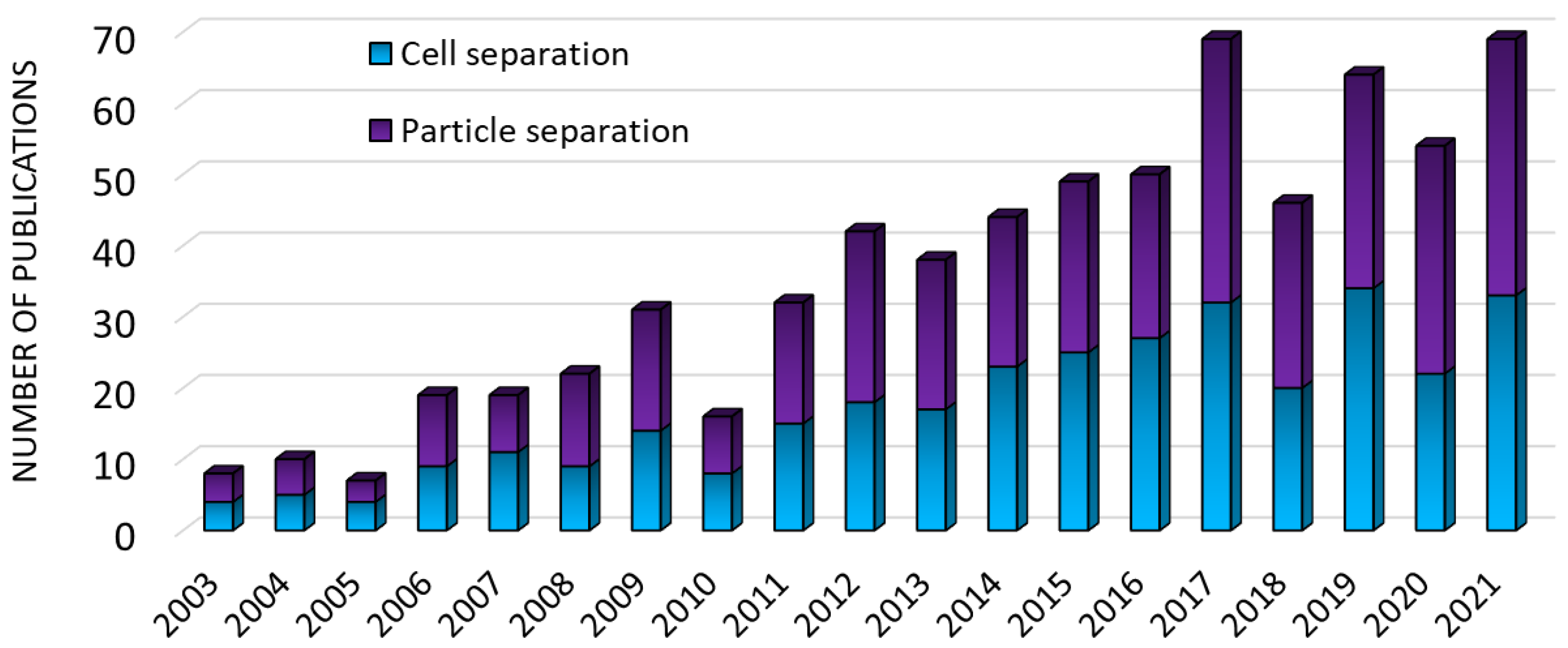
Figure 1. Number of documents published in the last two decades (up to 2021) related to the use of numerical modeling for the microfluidic separation of particles and cells, and found in the Scopus database using the keywords ‘‘cell separation”, “particle separation”, “simulation”, and “microfluidics”.
Processes 10 01226 g001
Figure 2. Separation of magnetic and non-magnetic materials inside a continuous-flow magnetophoretic microdevice [79]. Reprinted with permission from Ref. [79], 2022, Elsevier.
Processes 10 01226 g002
Figure 3. Induced dipole of the particle/cell and medium in the presence of a nonuniform electric field and generation of positive and negative dielectrophoresis (pDEP and nDEP, respectively) [15].
Processes 10 01226 g003
Figure 4. (a) Schematic of a general surface acoustic wave (SAW)-based acoustophoretic device composed of lithium niobate (LiNbO3) substrate, interdigital transducers (IDTs), and a polydimethylsiloxane (PDMS) microchannel. (b) Cross-sectional view of the device [72].
Processes 10 01226 g004
Figure 5. Device designed by Civelekoglu et al. [36] for cell sorting based on the expression of surface molecules. Immunomagnetically labeled cells are introduced to the microfluidic device from a single inlet. Sheath-flow-focused cells deflect in the transverse axis based on their magnetic load under an external magnetic field as they traverse the microfluidic chip. Cells sorted into different outlets generate digitally-coded electrical signals via a code-multiplexed Coulter counter array. The electrical signal is decoded to quantify the spatial distribution of cells, and an expression histogram is produced via computational analysis of sensor signals.
Processes 10 01226 g005
Figure 6. Flow patterns (blood in red, aqueous buffer in blue) simulated by Gomez-Pastora et al. [33] showing the effect of the bead motion on the fluid flow while the particles are magnetically separated. Reproduced with permission from Gómez-Pastora, J.; Karampelas, I.H.; Bringas, E.; Furlani, E.P.; Ortiz, I, Numerical analysis of bead magnetophoresis from flowing blood in a continuous-flow microchannel: Implications to the bead-fluid interactions; published by Sci, 2019. (a) One-way coupling model. (b) Two-way coupling model. (c) Two-way coupling accounting for the effects of bead volume.
Processes 10 01226 g006
Figure 7. Simulation studies performed by Ettehad et al. [15] showing the DEP separation of live and dead yeast cells. (a) Frequency: 3 MHz; (b) Frequency: 90 kHz.
Processes 10 01226 g007
Figure 8. SAW-based device employed by Richard et al. [1] to separate blood cells. (a) SU-8 microchannel designed for the separation, showing the approach employed for first focus and second separate RBCs from platelets; (b) SSAW focusing and separation of the cells; (c) Results with no applied SAW; (d) Results after applying the acoustic field.
Processes 10 01226 g008
Table 1. Simulation studies dealing with particle and cell magnetophoresis in microchannels.
Material to Be SeparatedFluid MediumFluid Velocity or Flow RateMagnetic Field SourceSimulation SoftwareExperimental ValidationReference
Bacteria (E. coli) conjugated to magnetic disks (1.5 µm)Aqueous solution5–120 µL/s3 × 3 NdFeB magnetsCOMSOL MultiphysicsYes[29]
Circulating tumor cells (CTCs, MCF-7) conjugated to magnetic beadsAqueous solution-Permanent magnetCOMSOL MultiphysicsYes[30]
Magnetic beads (1–4.5 µm) conjugated to cells (10–30 µm)Aqueous solution100–250 mL/h16 NdFeB magnetsOpenFOAMYes[31]
Magnetic beads
(2.29 and 4.9 µm)
Blood and aqueous solutionUp to 1.5 µL/sPermanent magnetFlow-3DYes[32]
Magnetic beads (5 µm)Blood and aqueous solutionUp to 3.5 cm/sPermanent magnetFlow-3DNo[33]
Red blood cells (RBCs) and
Bacillus spores
Aqueous solution0.1–10 mL/hPermanent magnetsCustom program
(Maple and MATLAB)
Yes[34]
Magnetic beads (4 and 8 µm)Water1 mm/sElectromagnetic coils-No[35]
Cancer cells (MCF-7 and MDA-MB-231) attached to magnetic beads (1 µm)Aqueous solution-NdFeB magnetCOMSOL MultiphysicsYes[36]
Iron oxide nanoparticles
(10 nm)
Aqueous solution5–100 µL/minNdFeB magnetCOMSOL MultiphysicsYes[37]
Diamagnetic (polyethylene) beads (3.2 and 4.8 µm)Ferrofluid0.5–2 µL/min5 NdFeB magnetsCOMSOL MultiphysicsYes[38]
Magnetic beads
(1.05 and 2.8 µm)
Aqueous solution3 mm/sSoft magnetic elements (Permalloy) externally magnetized (NdFeB magnet)ANSYS FLUENTNo[27]
DNA attached to magnetic beads (2.8 µm)Aqueous solution5–10 µL/minMagnet arrayCOMSOL MultiphysicsNo[39]
DNA attached to magnetic beads (1 µm)Aqueous solution5–10 µL/minPermanent magnetCOMSOL MultiphysicsNo[40]
Malaria infected RBCs and magnetic particles
(4.8 and 9.6 µm)
Water0.18–20 µL/minMagnet arrayCOMSOL Multiphysics and MATLABYes[41]
DNA attached to magnetic beads (2.8 µm)Water5–15 µL/minElectromagnetic coilCOMSOL Multiphysics and MATLABNo[42]
Magnetic particles
(40–280 nm)
Aqueous solution0.01–0.04 mL/hNdFeB magnetCOMSOL Multiphysics and MATLABYes[43]
Table 2. Simulation studies dealing with particle and cell dielectrophoresis in microchannels.
Material to Be SeparatedFluid MediumFluid Velocity or Flow RateElectric Field (Frequency/Voltage)Simulation SoftwareExperimental ValidationReference
Polystyrene (PE) beads (8 µm) and leukemia cells (K562, KG1)Aqueous solutions40–50 nL/sF = 300 kHz, 10 MHz (0.5–5 V)COMSOL MultiphysicsYes[44]
PE beads (2, 6, 8 µm)Water0.13 mm/sF = 500 kHz (0.2 V)FEM algorithmYes[45]
CTCs (MDA-MB-231 breast cancer cells) from RBCsPhosphate buffer saline (PBS)0.5–2.5 µL/minF = 1 kHz (10 V)COMSOL MultiphysicsNo[2]
Platelets, white blood cells (WBCs) and RBCsAqueous solutions100–800 µm/sF = 0.1–1000 kHz
(3–5 V)
COMSOL MultiphysicsYes[9]
PE beads (0.5–2 µm)WaterNo flowF = 1 MHz (6 V)COMSOL MultiphysicsYes[11]
E. coli from RBCs and plateletsAqueous solutions134–853 µm/sF = 1 Hz to 1 THz
(0–130 V)
COMSOL MultiphysicsYes[46]
Platelets and RBCs from bloodPlasma150–850 µm/sF = 100 kHz (5 V)COMSOL MultiphysicsNo[47]
Cancer cells (Raji cells) from PE beadsAqueous solutions1 mL/min0.5–2.5 VANSYS Inc. softwareYes[48]
Live and dead yeast cells (Saccharomyces cerevisiae RXII)Water1 µm/sF = 1 kHz–20 MHz
(Up to 20 V)
COMSOL MultiphysicsYes[15]
PE beads (5 and 10 µm)Water300 µm/sF = 1 MHz (6–22 V)COMSOL MultiphysicsYes[49]
RBCs and plateletsAqueous solutions134–853 µm/sF = 100 kHz (3–7 V)COMSOL MultiphysicsYes[50]
RBCs and CTCs (MDA-MB-231, breast cancer cell)Water500 µm/sF = 100 kHz (10 V)COMSOL MultiphysicsNo[51]
Monocytes from T-cell acute lymphoblastic leukemia (RPMI-8402)Aqueous solutions0.8 mL/hF = 110 kHz
(up to 16.5 V)
COMSOL MultiphysicsYes[20]
PE beads (5, 10 and 20 µm)PBS0.5–6 µL/minF = 1 MHz (up to 40 V)COMSOL MultiphysicsYes[52]
PE beads (5.5 and 15.6 µm) and osteosarcoma (MG-63 cells), and bone marrow cellsPBS20–100 nL/minF = 1–5 MHz (5–12 V)FlexPDE softwareYes[53]
CTCs (MDA-MB231) and RBCsWater134–800 µm/sF = 10 kHz (8–12 V)COMSOL MultiphysicsNo[54]
PE beads (1, 3.2, 10 µm)Aqueous solutions100–500 µL/minF = 150 kHz (10 V)COMSOL MultiphysicsYes[55]
CTCs (MDA-MB-231) and RBCsPBS180- 500 µm/sF = 100 kHz (10 V)COMSOL MultiphysicsYes[56]
Cancer cells (MD-231, HT-29) T-lymphocytes, RBCs and plateletsAqueous solutions134–853 µm/sF = 5–100 kHz
(up to 13 V)
Custom FEM solverYes[57]
PE beads (2, 3, 3.5, 5 µm) and RBCs, WBCs and cancer cells (MDA-MB-231)PBS20–200 µm/sF = 100–270 kHz
(up to 29 V)
OpenFOAMYes[58]
Beads (1.8, 5 µm)Water0.01–4 mm/sF = 100 kHz (0.5–8 V)STAR-CCM+No[59]
Cancer cells (HOP-62, HOP-92, NCI-H226, NCIH23, EKVX) from blood cellsAqueous solutions200–400 µm/sF = 100 kHz (1.6–2.2 V)-No[60]
CTCs (MDA-231) and WBCs (granulocytes)Aqueous solutions-F = 100 kHzCOMSOL MultiphysicsNo[61]
PE beads (4.42 µm)WaterNo flowF = 1 MHz (6–10 V)COMSOL MultiphysicsYes[3]
Particles emulating blood cells (3, 7, 15, 20, 25 μm)PBS750–1600 µm/sF = 110 kHz (4.8–44 V)COMSOL MultiphysicsNo[62]
CTCs from blood cellsWaterUp to 5 mm/s1–15 VANSYS FluentNo[63]
RBCs from bacteria
(Clostridium difficile) cells
Aqueous solutions10–40 µm/sF = 250 kHz–50 MHz (0.1–0.5 V)COMSOL MultiphysicsNo[64]
PE beads (3, 4, 6, 7 µm)PBS42.5–400 µm/sV= 80–90 V-Yes[65]
Beads (0.5, 3.5, 10 µm)Water30–50 µm/sF = 1–10 MHz (1–8 V)COMSOL MultiphysicsNo[66]
CTCs (MCF-7) from WBCs and RBCsPlasma100 µm/s2–3 VCOMSOL MultiphysicsNo[67]
Yeasts and PE beads (4 µm)Aqueous solutions1 mm/sF = 0.1–10 MHz
(30–60 V)
COMSOL MultiphysicsNo[68]
Platelets from RBCsAqueous solutions134–1500 µm/sF = 0.1–1 MHz
(10–20 V)
COMSOL MultiphysicsNo[69]
Table 3. Simulation studies dealing with particle and cell acoustophoresis in microchannels.
Material to Be SeparatedFluid MediumFluid Velocity or Flow RateAcoustic Field (Frequency/Wavelength)Simulation SoftwareExperimental ValidationReference
Particles (10 µm in size)WaterNo flowλ = 60 µmCOMSOL MultiphysicsNo[70]
Malaria infected RBCsPlasmaNo flowF = 0.985–1.007 MHzCOMSOL MultiphysicsYes[16]
PE and iron oxide particlesWaterNo flowF = 13.3 MHzCOMSOL MultiphysicsYes[14]
Blood cells (2–30 µm)Water0.01 m/sF = 50 MHzCOMSOL MultiphysicsNo[2]
RBCs and plateletsPlasma0.5 µL/minF = 12.7–13 MHzCOMSOL MultiphysicsYes[1]
RBCs, WBCs, and platelets Water15 mm/sF = 7.4 MHzCustom FEM codeYes[71]
PE beads (10 µm)Acetic acid, water, ethanolNo flowF = 14 MHzCOMSOL MultiphysicsYes[72]
PE beads (1, 5, 10 µm)Water4–5 mm/sF = 19.8 MHzCOMSOL Multiphysics and MATLABYes[19]
Blood cellsPlasma22–100 μL/minF = 1.03 MHzCOMSOL MultiphysicsYes[73]
PE beads (5, 10 µm)-No flowλ = 100–200 µmCOMSOL MultiphysicsYes[8]
PE beads
(3, 5, 7, 10, 15 µm)
Water3–67 mm/sF = 2–5 MHzCOMSOL MultiphysicsNo[24]
PE beads (1.8, 5 µm)WaterNo flowΛ = 200, 300 and 600 µmCOMSOL MultiphysicsNo[74]
Particles (0.1–150 µm)Water2 mm/sF = 3 MHzCAD/CAE softwareNo[75]
Particles (10 µm)Oil1–10 mm/sF = 3–20 MHzCOMSOL MultiphysicsYes[76]
Publisher’s Note: MDPI stays neutral with regard to jurisdictional claims in published maps and institutional affiliations.