Article

A Primary Support Design for Deep Shaft Construction Based on the Mechanism of Advanced Sequential Geopressure Release

1
School of Resources and Civil Engineering, Northeastern University, Shenyang 110819, China
2
Sinosteel Maanshan Institute of Mining Research Co., Ltd., Maanshan 243000, China
*
Author to whom correspondence should be addressed.
Processes 2022, 10(7), 1376; https://doi.org/10.3390/pr10071376
Submission received: 26 June 2022 / Revised: 10 July 2022 / Accepted: 12 July 2022 / Published: 14 July 2022

Abstract

:
The construction of 1500 m depth shaft in Xincheng Gold Mine, China, faces complex stress conditions such as high geostress (>50 MPa), high ground temperature (>50 °C), high water-pressure (>9 MPa), and highly corrosive. Traditional deep shafts excavated by the sinking and lining method cannot adapt to high geostress problems, such as rock bursts and large deformations, etc., in the deep shaft construction process. To avoid and adjust the high geostress induced the rockburst and large deformations, the mechanism of the advanced sequential geopressure release (ASGR) has been proposed for the ground control in deep shaft construction. In this paper, the safe distance between the concrete lining and the shaft excavation face is determined based on the ASGR mechanism, which can provide the space for geopressure release, and primary support based on rock mass quality and numerical simulation was employed to control the geopressure and deformation. A new support scheme for the deep shaft is proposed, using long bolts to restrain severe deformations, metal mesh, and a double reinforcement bar to improve the induced stress distribution. According to the results, the construction scheme of deep shaft has been improved, and the safe support distance of the proposed scheme is determined to be 12 m, with an interval of three excavation cycles. Compared to the original scheme of shaft lining after excavation, the proposed scheme based on the ASGR mechanism can effectively improve the geopressure release and benefit from controlling the rockburst and large deformation of deep shaft induced by high geostress conditions. The stress distribution in the lining is more uniform, and safety factor of the lining is increased to 2.0, which is benefit the long-term stability of deep shaft.

1. Introduction

Shafts are the most important capital opening for deep mines, providing all services for mining underground mineral deposits [1,2,3]. Deep shafts in hard rock mines at depths exceeding 1500 m are becoming commonplace at home and abroad [4,5], and the drill-blasting method [6,7] is the primary method for sinking after reaching the bedrock under normal ground conditions. The sinking cycle consists of drilling, blasting, mucking, hoisting, establishing support, and shaft lining, including some auxiliary operations. The advance of the concrete lining of a shaft sunk in a hard rock mine is normally close to the bottom of the excavation (see Figure 1) [8,9].
The high stress and ‘anisotropy’ (including rock mass, structure, stress, etc.) complex geomechanical environment, in which a thousand-meter-deep shaft was built, can cause the collapse, rock burst, and impact in the rock surrounding the shaft and the main roadway at the bottom of the shaft during shaft construction. Given the problems of rock mechanics and disaster control in deep mine shaft construction [10,11,12], many scholars have studied the basic theory of mechanics in this type of construction. Wang Jinping [13] simplified the vertical shaft as a thick-walled cylinder. By analyzing that the external side of negative friction is subjected to axisymmetric tangential load, it is considered that the radial variation of shaft wall stress in the deep cross section can be ignored, and the theoretical solution of shaft wall stress is established. Based on pile theory and the generalized shear displacement method, Su [14,15] established a theoretical solution based on the coupling effect of wellbore and stratum, and analyzed the magnitude and distribution of axial stress, considering the relative displacement of wellbore and stratum. On the basis of Su [5,14], Zhou [16] discusses the completion method of the double series method, decomposes the finite long shaft wall in any axisymmetric problem into symmetry and antisymmetry, and gets the theoretical stress solution of the shaft wall strictly satisfying all boundaries by superposing the stress of the two cases. The construction of shaft sinking is very complex [17], and the complete solution for the distribution of stresses and displacements around a circular opening in an opening is given by Kirsch from the theory of elasticity [18,19]. The characteristics of deep shafts are that the stress boundary conditions in the axial direction of the shaft are asymmetrical, nonuniform, and nonlinear distributions (see Figure 2). The conditions for solving plane problems are not satisfied. Therefore, the three-dimensional mechanical model must be used in mechanical modeling. The stress boundary conditions along the radial direction of the shaft are asymmetrical. An elliptic section should be used to counter the nonuniform stress field in the radial direction of the shaft on the premise of knowing the direction and magnitude of the in-situ stress [20,21,22].
The lining is commonly designed and expected to provide ‘active’ structural support for the long-term stability of deep shafts worldwide [23,24]. Linings of shafts generally consist of concrete, steel fiber concrete, reinforced concrete or steel, a double cylinder, or a combination of these lining types. Some rules of thumb [25,26,27,28] have provided valuable suggestions for designing concrete linings in deep shafts: the minimum and maximum lining thicknesses for poured concrete are 200 mm and 1000 mm, respectively [27,28]. Xue [29] developed high-performance concrete material as the structural material of shaft support in view of the difficult situation of shaft support in a coal mine. The permeability experiment under high water pressure load was carried out by a triaxial testing machine, and the permeability change model under the coupling state of stress and seepage was established. Finally, through theoretical analysis and numerical calculation verification, it is found that the damaged area of the shaft wall under high water pressure is quite different from that of traditional methods. Zhou [30] for pore water bedrock section of the wall design in a series of problems such as study, compared the assignment of shaft lining external water pressure, lining and surrounding rock strength ratio, time effect of shaft excavation, and whether there is a bolt, etc. The influence of various factors on the shaft mechanical characteristics, more intuitively reveals the time variation law of interaction of various factors, it can provide a reference for the lining design of the bedrock section of the shaft under high hydraulic geological conditions. Concrete strength is generally between 20 and 25 MPa in underground hard mines [31]; however, concrete lining in circular shafts develops greater strength than that of standard concrete, arriving at 25 to 70 MPa. High-strength concrete linings have been developed, and the uniaxial compressive strength (UCS) of concrete exceeds 100 MPa with the addition of 25 to 35% fly ash or reinforcing steel [32,33]. However, since the 1980s, more than 200 shafts have been deformed and damaged in China [34,35]. The concrete lining is sensitive to the movement of the rock mass, and the immediate instability after taking the load after the settlement is difficult to repair [36].
A shaft wall in country rock, which is in an elastic state of stress, can withstand outside pressure without any lining, and if the concrete lining is installed, its thickness is by no means critical [37]. If the wall rock is stiffer than the concrete lining, in situ stresses are not transmitted to the concrete lining from the country rock. The only structural role of the concrete lining is a ‘passive’ role, and it only stops the development of relaxation and prevents the wall rock from unraveling or sloughing. However, the concrete lining cannot carry the deformation from the plastic zone that decays completely during the final lining installation [37]. Thus, in this paper, the primary support method is presented and designed to reinforce the stress-relieved zone based on empirical, analytical, and numerical methods according to the brittle properties of wall rock and induced stress conditions.

2. The Primary Support Principle for the Prestress-Relieved Zone

The deformation caused by country rock failure acts on the concrete walling, resulting in the tensile/compressive and shear failure of the concrete walling. The concept of ASGR in a deep shaft is put forward and can increase the distance between the primary support and driving face and release the high stress accumulated in country rock (see Figure 3a). The core idea of the concept of ASGR in a deep shaft is to overcome the traditional construction method of ‘excavation in one cycle and support in another.’ The disadvantage of the traditional construction method is that it simply improves the strength and thickness of lining concrete to strengthen country rock support. The high stress accumulated in the country rock of the shaft can be released by increasing the distance between the lining and the driving face (see Figure 3b).
Therefore, in the initial stage of the stress adjustment of country rock, the stress of country rock is less than the strength of rock everywhere. At this time, the physical state of the surrounding rock is not changed, and it is still in the elastic state. The mechanical response process of country rock in shaft excavation is that the country rock produces elastic deformation and displacement, and a new stress equilibrium is achieved. With the further adjustment of country rock stress, the local stress of country rock exceeds the strength of the rock mass, the physical state of the wall rock changes, yielding failure occurs, and a plastic zone is formed. On the one hand, the formation of the plastic zone makes the stress of the country rock transfer deep; on the other hand, it deforms to the direction of the shaft and gradually ‘releases’ the internal stress of the plastic zone (see Figure 4).
With reference to the concept of prestress relief for deep shaft sinking, the detailed steps of the design of the primary support are as follows:
Step 1: Engineering geological survey. To determine the geological conditions in the area, we focus on rock masses, joints, structures, hydrology, and other geological conditions to study the shaft stability and support methods.
Step 2: Rock mechanics test. Rock mechanics tests are carried out in the laboratory to obtain the rock mechanics parameters of the rock.
Step 3: Rock mass classification. Based on the RMR, Q, and GSI methods, the surrounding rock mass of the shaft is classified.
Step 4: Estimation of the mechanical parameters of the rock mass. According to the results of the rock mass classification and rock mechanics tests, the mechanical parameters of the wall rock mass are estimated. The obtained rock mass mechanical parameters can be used in later numerical simulations.
Step 5: Support design of the shaft surrounding the rock. According to the empirical support chart (RMR and Q), the support design of the shaft surrounding the rock is carried out.

3. Field and Laboratory Studies

The new main shaft of the Xincheng Gold Mine is located in Shandong Province, in eastern China. The geomorphic unit belongs to a hilly region, and the elevation of the ground level ranges from 2.23 m to 31.88 m ACD (Admiralty Chart Datum). The new main shaft was designed to have a depth of 1527 m and a bottom elevation of −1488.1 m, with an inside diameter is 6.7 m [19]. The lining thickness is 300 mm (−622 m level above) and 400 mm (−622 m level below), and the compressive strength of the concrete is 25 MPa.
The field and laboratory studies include field observations, boreholes, and discontinuity surveys, and laboratory testing. Engineering geological drilling of ZCK-1 was carried out at 25 m parallel to the new shaft, with hole depths ranging from −930 m to −1570 m. The drilled cores are mainly porphyritic granodiorite and cataclastic granodiorite, which are brittle and of good quality (see Table 1 and Figure 5). The statistical data of the discontinuity parameters obtained from the study region are given in Table 2.
The lithology of these sites is unitary and is mainly medium-grained granite. The physical and mechanical properties of the rocks were determined from laboratory testing on intact rock samples following ISRM (1981) recommended methods, and the test results are given in Table 3.
The Q-system was developed at the Norwegian Geotechnical Institute (NGI) [39] based on approximately 200 case histories of tunnels and caverns. The Q-system was updated on several occasions and is now based on 1260 case records [40]. Barton [41] recompiled the system and made changes to support recommendations to reflect the increasing use of steel fiber reinforced shotcrete in underground excavation support. The quality of rock masses is described using six parameters, RQD, joint set number (Jn), joint roughness (Jr), joint alteration (Ja), joint water reduction factor (Jw), and stress reduction factor (SRF). The Q rating is derived from the following expression by combining these six parameters:
Q = R Q D J n J r J a J w S R F
Combined with the field investigation results, the Q classification of the wall rock of the new main shaft in the Xincheng Gold Mine in the depth range of −930~−1280 m is as follows (Table 4).
The RMR classification system was initially developed by Bieniawski [42] based on shallow tunnels in sedimentary rocks. It was modified several times, and at present, the latest 1989 version of RMR ratings [43] is widely used. It employs six parameters: uniaxial compressive strength (UCS) of intact rock material, rock quality designation (RQD), spacing of discontinuities, condition of discontinuities, groundwater conditions, and orientation of discontinuities. Each parameter is given a rating of importance for a particular situation. The six input parameters are summed to yield RMR rating results. According to the above RMR index scoring method, the RMR indices of the rock mass are graded as follows (Table 5).
The rock mass properties, such as the Hoek–Brown constants, UCS ( σ c m a s s ) and uniaxial tensile strength of the rock mass ( σ t m a s s ), deformation modulus ( E m a s s ), and shear strength parameters, were calculated using different empirical equations based on rock mass classification systems. The averages of these parameters are used as input data in the numerical modeling. Combined with the Hoek Brown criterion, the mechanical parameters of the rock mass at different shaft depths are estimated, as shown in Table 6.
The stress redistribution characteristics of the shaft cross-section and the longitudinal section are closely related to the failure and deformation of wall rock after excavation. Obtaining the stress redistribution of the surrounding rock can determine the failure range (radius of the plastic zone) of the shaft and provide a reference for selecting bolt length and calculating the support pressure.
According to the water quality analysis results of the aquifer, the water chemistry type is SO4-Cl-Na type, the salinity is 3.43 g/L, PH is 7.10, SO42 is 1121.5 mg/L, Cl is 2281.4 mg/L. According to class II environmental assessment, groundwater has a weak corrosion effect on concrete structures. According to the influence of stratum permeability, groundwater has no corrosive effect on concrete structures, but a moderate corrosive effect on steel structures. It has no corrosion effect on steel bars in concrete in long-term immersion environments. Moderate corrosion in alternating wet and dry environments.
Under the condition of a non-hydrostatic stress state, the analytical solution of the plastic zone and stress distribution of the shaft surrounding rock cannot be obtained accurately. Only an approximate solution can be obtained. Therefore, FLAC3D numerical software is used to calculate the plastic zone and stress distribution of the surrounding rock. The size of the calculation model is 50 × 50 × 50 m, and the diameter of the shaft is 7.5 m. The rock mass mechanical parameters and in situ stress conditions of the core at −1276 m of the new main shaft are used.
Figure 6 shows the elastic-plastic solution of the wall rock of the shaft. As shown in Figure 6a, due to shaft excavation, stress concentration occurs in the redistribution of wall rock stress, which exceeds the strength of the surrounding rock, and the wall rock enters the plastic state. The appearance of the plastic zone of the wall rock makes the stress transfer to the deep part of the wall rock continuous, and at the same time, the stress in the plastic zone is gradually released. In Figure 6b, the maximum displacement of the wall rock is 24 mm, and in Figure 6c, the thickness of the plastic zone of the wall rock is 2.35 m.

4. Primary Support Design of Xincheng Shaft

The main function of the primary support is to release a certain displacement of the surrounding rock to ensure the release of surrounding rock stress. In addition, the primary support prevents the instability failure of the structural plane in the surrounding rock.
The support pressure of the rock surrounding the shaft mainly includes the deformation pressure of the surrounding rock and the pressure of the loose surrounding rock. First, in view of the deformation pressure of the rock surrounding the shaft, the support capacity of the supporting structure is relatively large. If the pressure is controlled by the rigid support of the supporting structure, the deformation energy inside the rock surrounding the shaft cannot be effectively released, which easily induces the occurrence of rock bursts. Therefore, it is necessary to release the deformation pressure of the surrounding rock in a stable and controllable way through the primary support. The surrounding rock of the new main shaft is a hard fractured rock mass, and its failure mode is the shear failure of the surrounding rock caused by excessive stress of the original rock. The anchor is the most commonly used treatment measure in controlling the unstable block.
According to the above discussion, the optional primary support for the shaft surrounding rock is anchor-net-beam support. The bolt can control the unstable block and has a certain deformation ability, while the wire mesh and double bars are used to prevent the falling of the broken rock block. The engineering analogy method is usually adopted in the selection of bolts, which is mainly the support design method for the surrounding rock in underground engineering based on the classification of rock mass geomechanics by Q and RMR. Supporting parameters are determined according to the domestic engineering analogy method. The length of the bolt can be determined according to the empirical formula proposed by Barton [39]:
l b = 2 + ( 0.15 B / E S R )
where B is the height without support, which is 12. ESR is the excavation support ratio, taken as 3. The length of the bolt is 2.6 m.
According to the RMR empirical method, the support parameter is 1.5 m × 1.5 m between bolt rows. According to the domestic engineering analogy method, the bolt length is 2 m, and the spacing between rows is 1 m. Combined with the actual specifications and according to the principle of convenient construction, the length of the anchor is 2.5 m, and the spacing between rows is 1.5 m ×1.5 m. Resin bolt support is adopted, the steel type is HRB400, and the pallet specification is 120 mm × 120 mm × 8 mm. Wire mesh is usually made of #8 wire diamond galvanized metal mesh. The bar is made of two parallel bars with a diameter of 8 mm welded at an interval of 80 mm and a length of 3 m. The design diagram of the primary shaft support is shown in Figure 7.
Through active control of the stress state and the stress distribution characteristics of the surrounding rock in the unlined section, the support structure will gradually bear the deformation pressure caused by the stress redistribution of the surrounding rock and release the high stress accumulated in the rock surrounding the shaft. The surrounding rock deformation, support constraints, and spatial constraints of the shaft excavation face are considered separately to determine the support pattern and suitable support type. Due to the delay of lining support, the rock surrounding the shaft has a certain tie and space to release stress and displacement. Moreover, after the stress redistribution of the surrounding rock, the internal stress of the surrounding rock is evenly distributed, and there is no shear force in the lining, which is conducive to the stability of the lining. A schematic diagram of ASGR is shown in Figure 8.

5. Comparison and Verification of Numerical Simulation between the Original Support and Proposed Support

The numerical modeling software FLAC3D is used to test the application effect of the proposed support construction method. Combined with the rock mass parameters and stress conditions at −1276 m of the new main shaft, the original support construction technology and the proposed scheme are compared and verified to test the support effect of the proposed scheme.

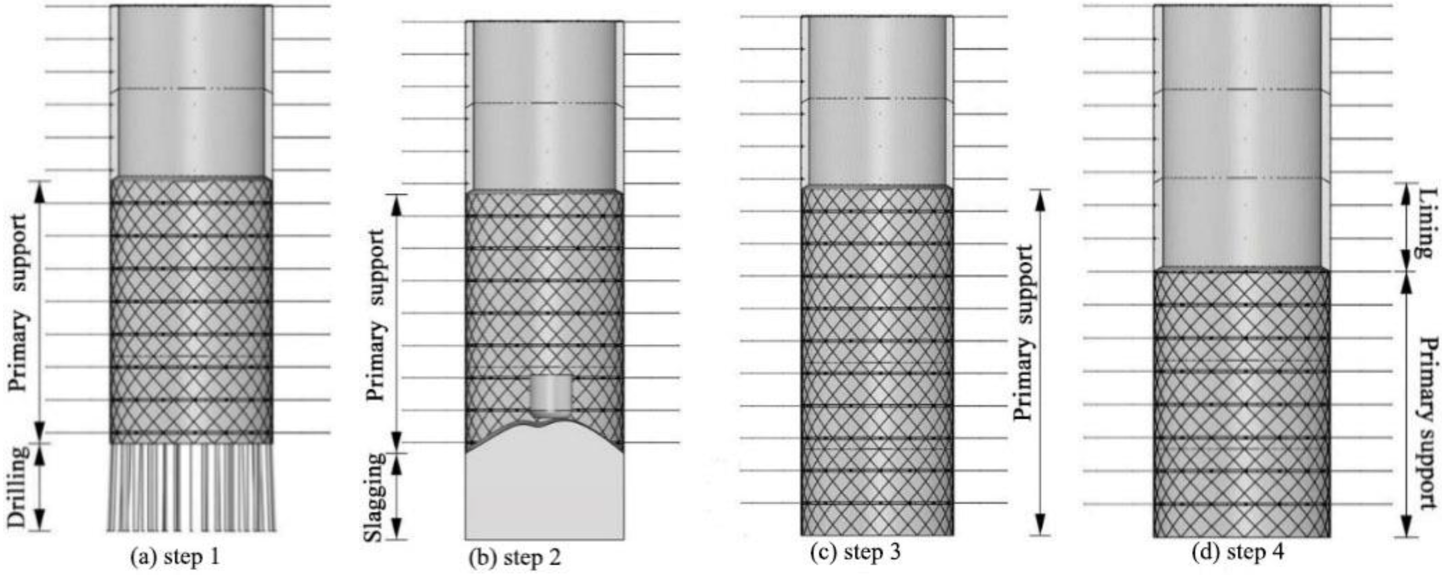
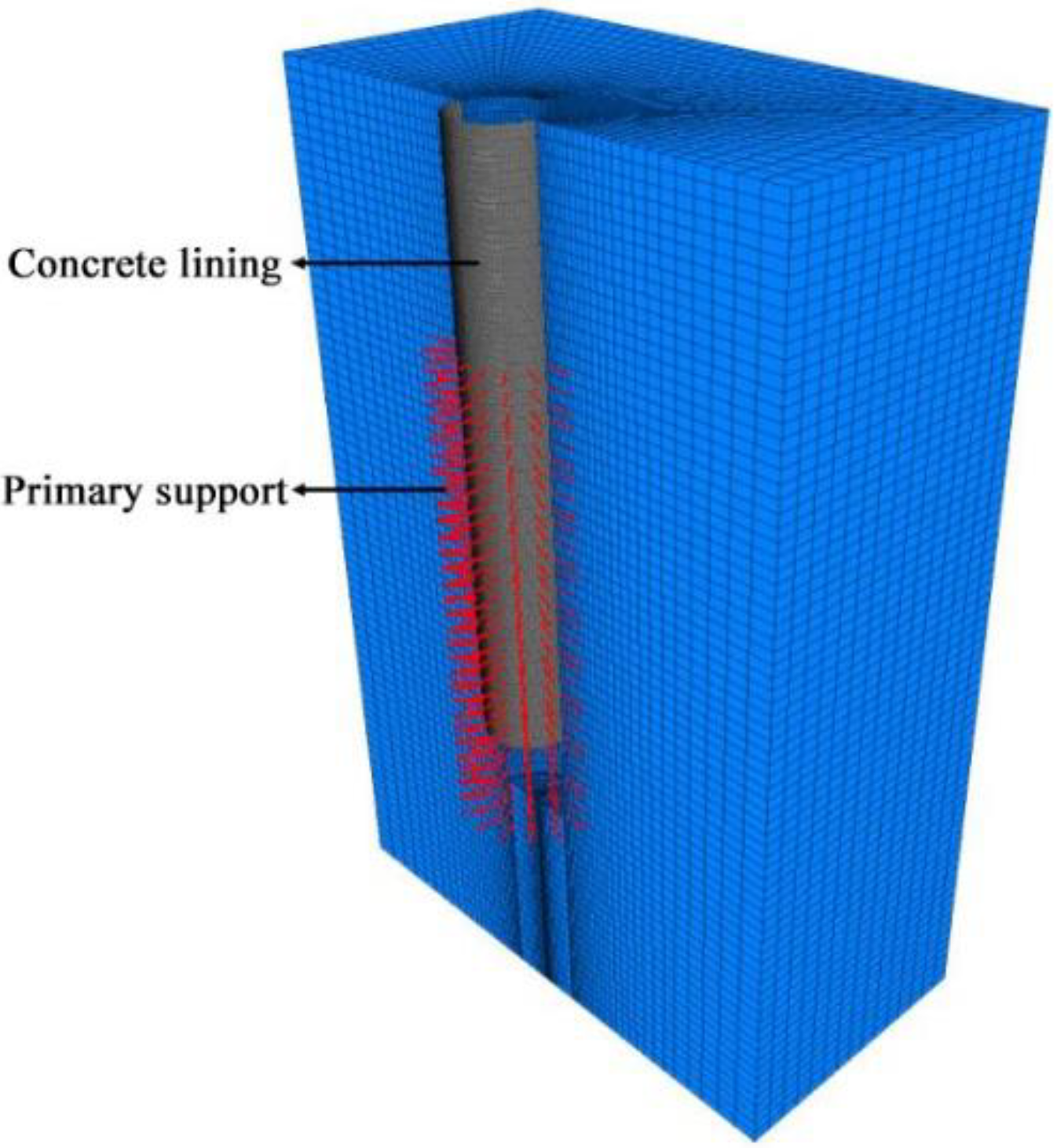
5.1. Design of the Numerical Modeling Scheme

The excavation diameter of the new main shaft in the Xincheng Gold Mine is 7.5 m. The model boundary is 50 m × 50 m × 76 m. The excavation footage of the shaft is 4 m, and the model is used 14 times for excavation and support. According to the original scheme and the proposed scheme, two kinds of excavation and support schemes were modeled.

5.1.1. Excavation and Support Construction of the Original Scheme

The original support construction scheme of the new main shaft of the Xincheng Gold Mine is a construction scheme of ‘excavation in a cycle and support in another’; that is after the shaft is excavated to 4 m, the surrounding rock of this section is supported with a concrete lining, with a lining thickness of 400 mm. According to the original scheme, the numerical calculation is carried out after every 4 m excavation of the model. This process mainly simulates the release process of stress and the displacement of the surrounding rock after the excavation of the shaft working face and to the pouring of the concrete lining. After the completion of lining casting, the surrounding rock of this section is numerically calculated. The calculation scheme is shown in Figure 9. All 13 steps of the excavation and support work are completed.

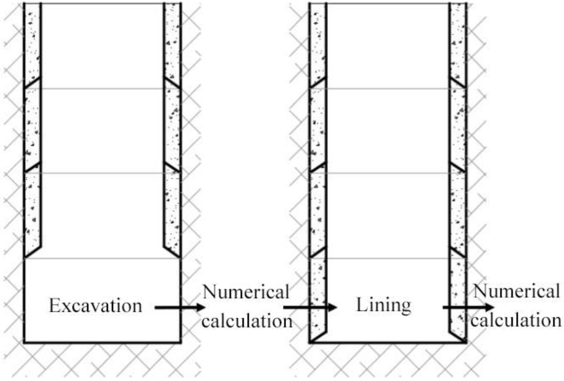
5.1.2. Improve the Construction of Excavation and Support

The proposed support construction methodology adopts the construction scheme of ‘excavations in three cycles and support in one cycle’. That is, when the height of the unlined surrounding rock of the shaft is excavated to 12 m, the concrete lining will be carried out for the surrounding rock roof, with the lining section being 4 m high and 400 mm thick. The surrounding rock with a height of 4 m close to the shaft excavation face is used for bolt support with a pattern spacing of 1.5 m. Similarly, after each excavation, the numerical calculation is carried out, and then the surrounding rock is supported and calculated, as shown in Figure 10.
After the modeling calculation of the two schemes is completed, the parameters of the lining and surrounding rock in the middle part of the shaft are compared. This comparison includes displacement, the plastic zone, and major principal stress. The safety factor of the lining of the two kinds of construction technology is also obtained. To optimize the calculation pattern, only a 76 m high rock mass above −1276 m is selected in the calculation area, so the boundary of the model is fully constrained by displacement. The calculation model is set up as shown in Figure 11.

5.2. Numerical Modeling Results and Analysis

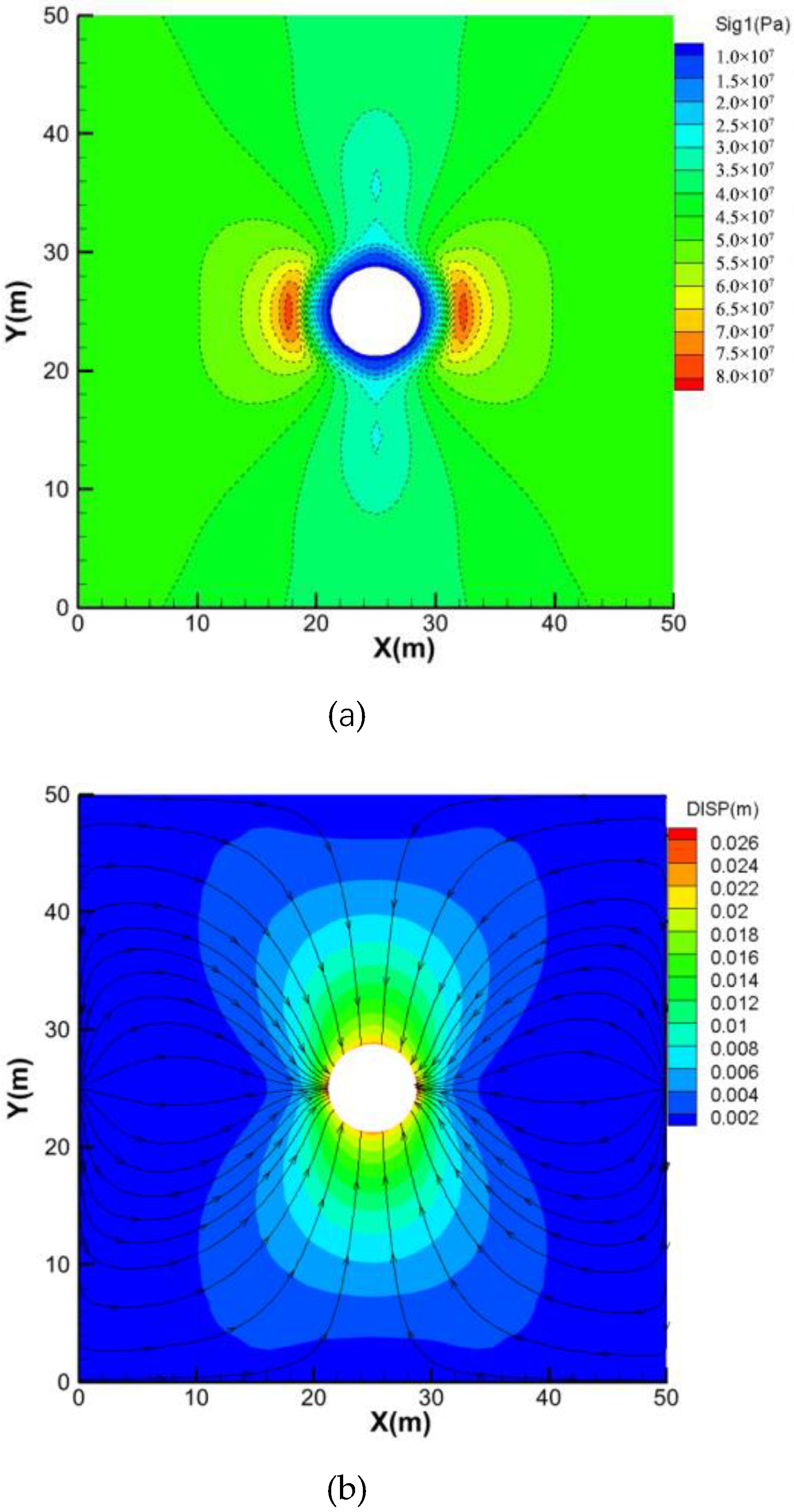
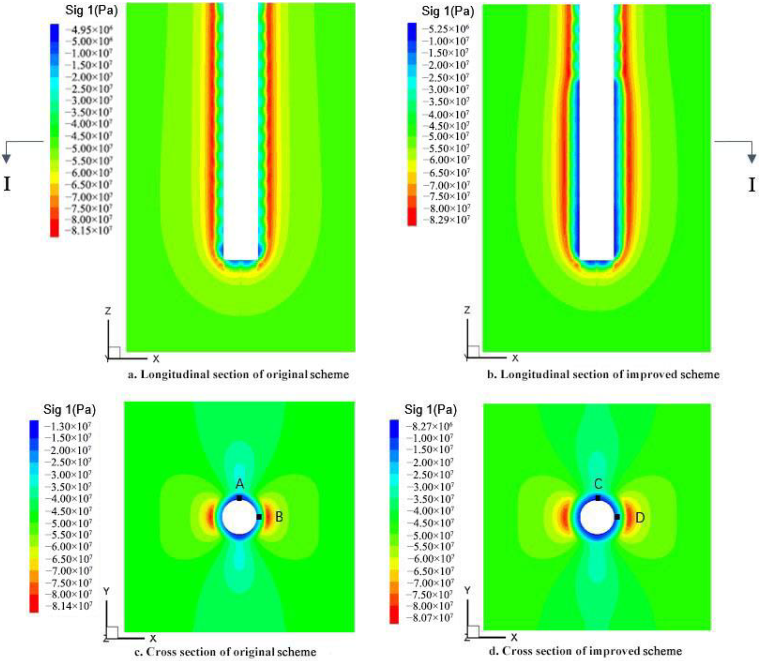
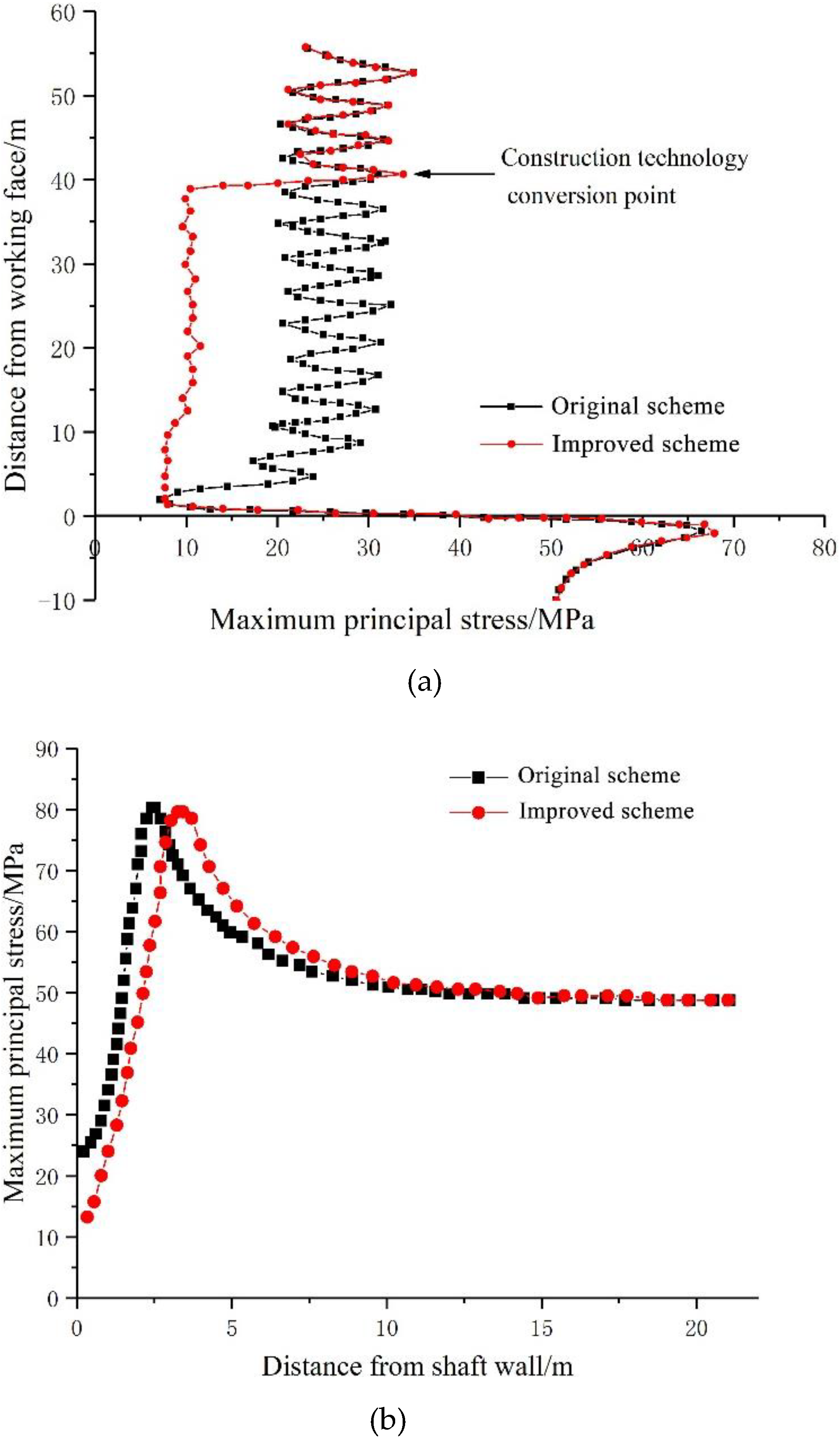
5.2.1. Stress Analysis of Surrounding Rock

It is known that the Y-axis direction of the calculation model is the direction of the major principal stress. In Figure 12, the longitudinal section is perpendicular to the Y-axis, and the transverse section is 46 m away from the working face.
According to the comparison of the longitudinal profile in Figure 12a,b of the major principal stress of the two processes, it can be concluded that the shaft lining stress of the original scheme is relatively large, with an average of 26 MPa, and the shaft lining stress of the proposed scheme is released with an average of 10 MPa. The stress concentration area of the shaft surrounding rock shifts from shallow to deep. According to the comparison of the two schemes’ major principal stress cross section, Figure 12c,d it can be concluded that the major principal stress around the shaft lining of the original process is relatively large. The circumferential stress distribution along the hole is uneven. As shown in Figure 12c,d, the major principal stress at Point A is 14 MPa, and that at point B is 23 MPa. The major principal stress around the shaft lining of the proposed scheme is small. The circumferential stress distribution is uniform. In Figure 12d, the major principal stress at point C is 8.5 MPa, and that at point D is 11 MPa.
Figure 13a shows the stress curve obtained by taking values along the longitudinal section of the shaft wall, and Figure 13b shows the stress curve obtained by taking values along the X direction of the cross section of the shaft.
According to Figure 13a, the major principal stress of the proposed scheme is less than that of the original scheme. Along the longitudinal direction, the stress curve of the wall rock of the shaft wall shows a repeated upward and downward trend. The average amplitude of the major principal stress fluctuation of the proposed scheme is 0.9 MPa, and the average fluctuation amplitude of the original scheme stress curve is 10.5 MPa, which shows that the proposed scheme is helpful in distributing the internal stress of the surrounding rock evenly. According to Figure 13b, the stress-bearing area of the proposed scheme is transferred to the deep part of the surrounding rock. The stress concentration area of the original scheme is close to the shaft lining. The high stress of the surrounding rock is a potential risk to the safety of the shaft.
The above results show that due to the delay of the lining support of the shaft lining, the rock surrounding the shaft has a certain time and space for stress displacement release. After the stress of the rock surrounding the shaft is redistributed, the stress distribution in the surrounding rock is uniform. There is no shear force in the lining, which is helpful to the stability of the lining. However, the distance between the original scheme lining support and the excavation face is relatively close, the stress release of the surrounding rock is less, and there is still substantial stress in the rock mass. With the excavation of the shaft, the stress of the surrounding rock will be applied to the lining, which will lead to an excessive load on the lining, a low safety factor, and even damage.

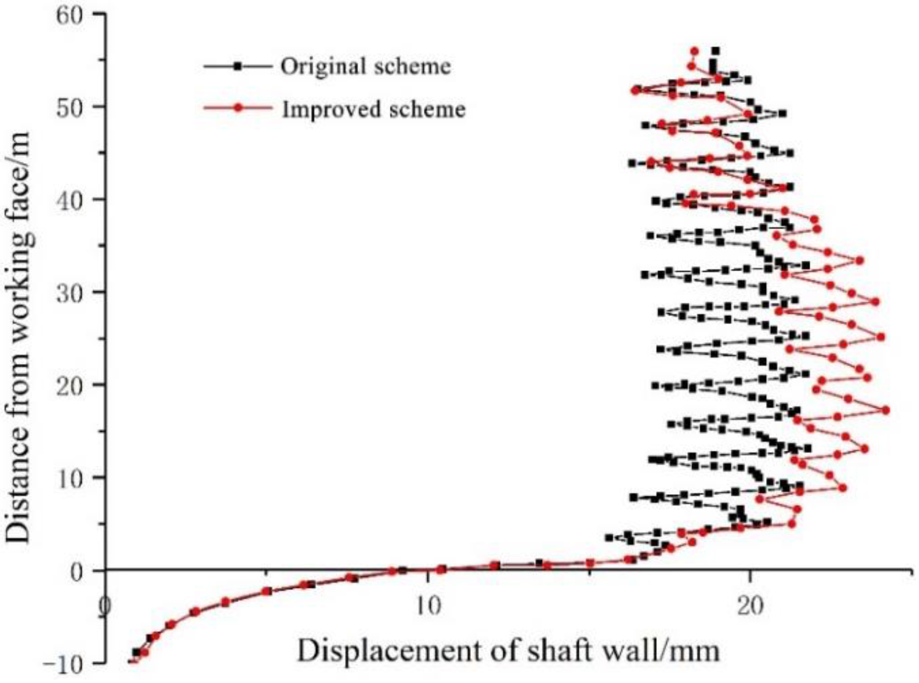
5.2.2. Displacement Analysis of the Surrounding Rock

Figure 14 and Figure 15 show that the displacement of the surrounding rock in the proposed scheme is enlarged, and the displacement of the surrounding rock is the manifestation of the stress release of the surrounding rock. The major displacement of the surrounding rock of the original scheme is 21.9 mm, and the major displacement of the surrounding rock after improvement is 24 mm. The original lining will bear more deformation pressure from the surrounding rock.

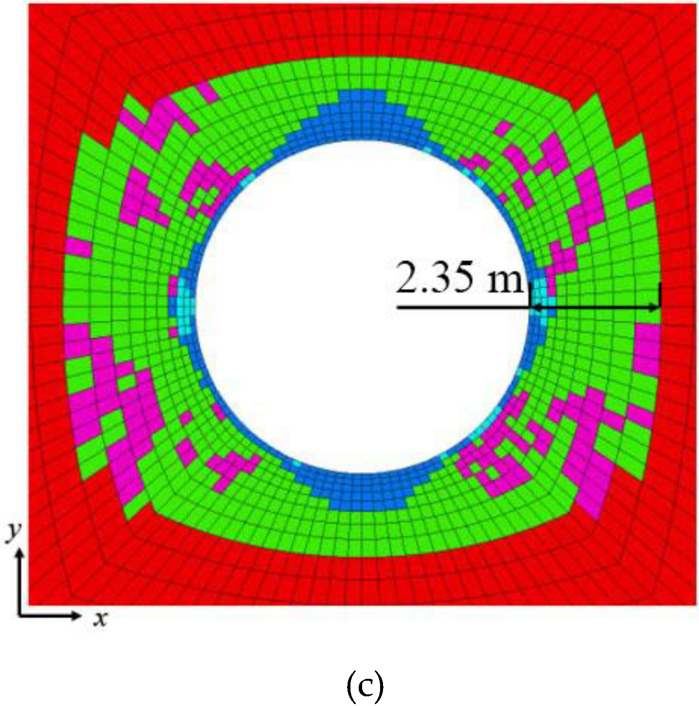
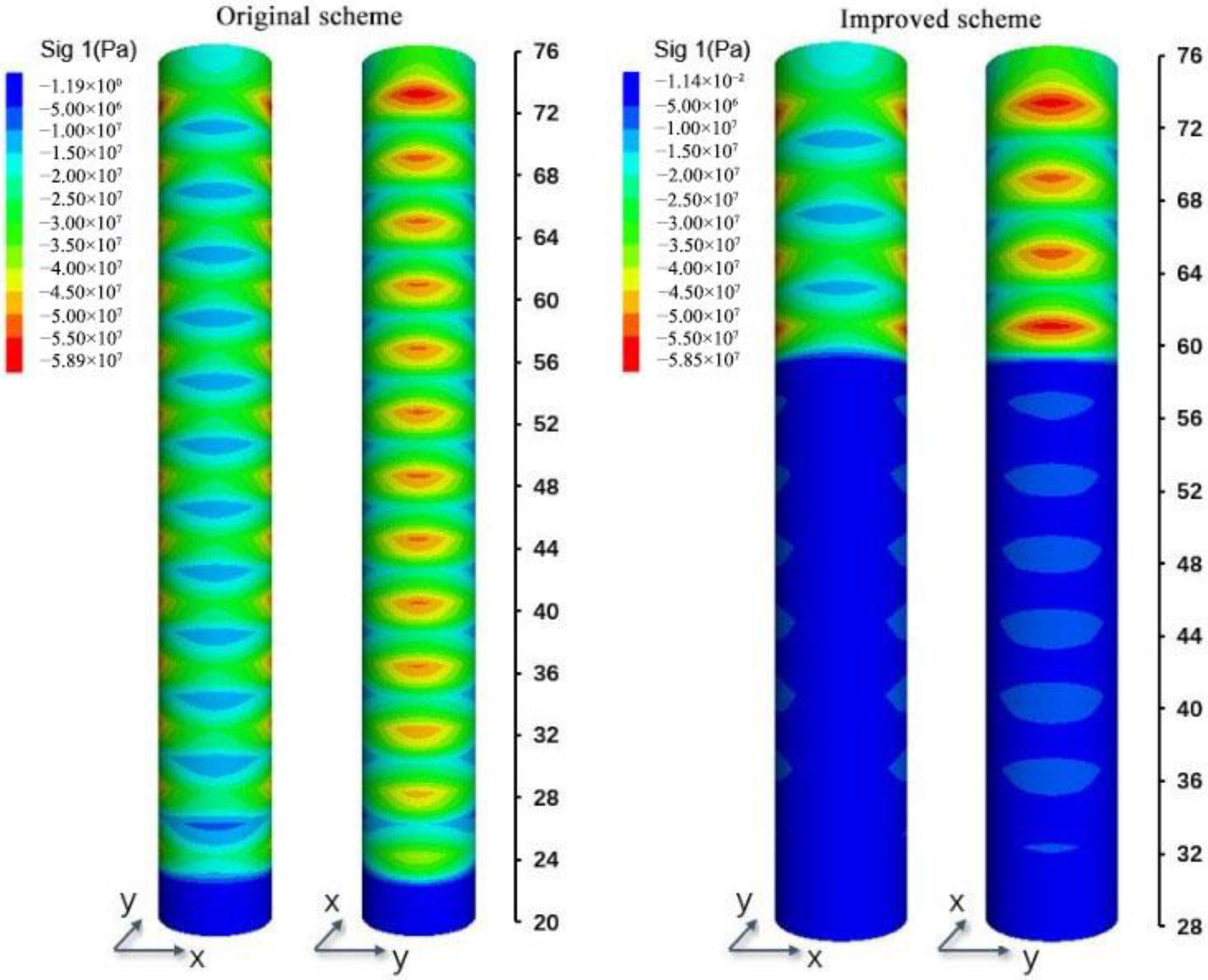
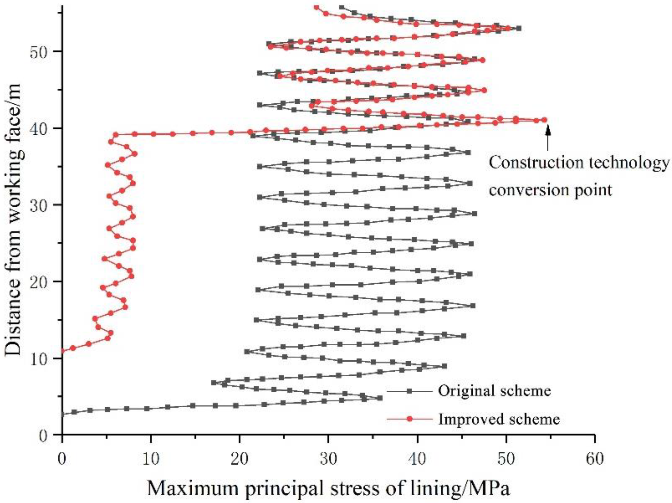
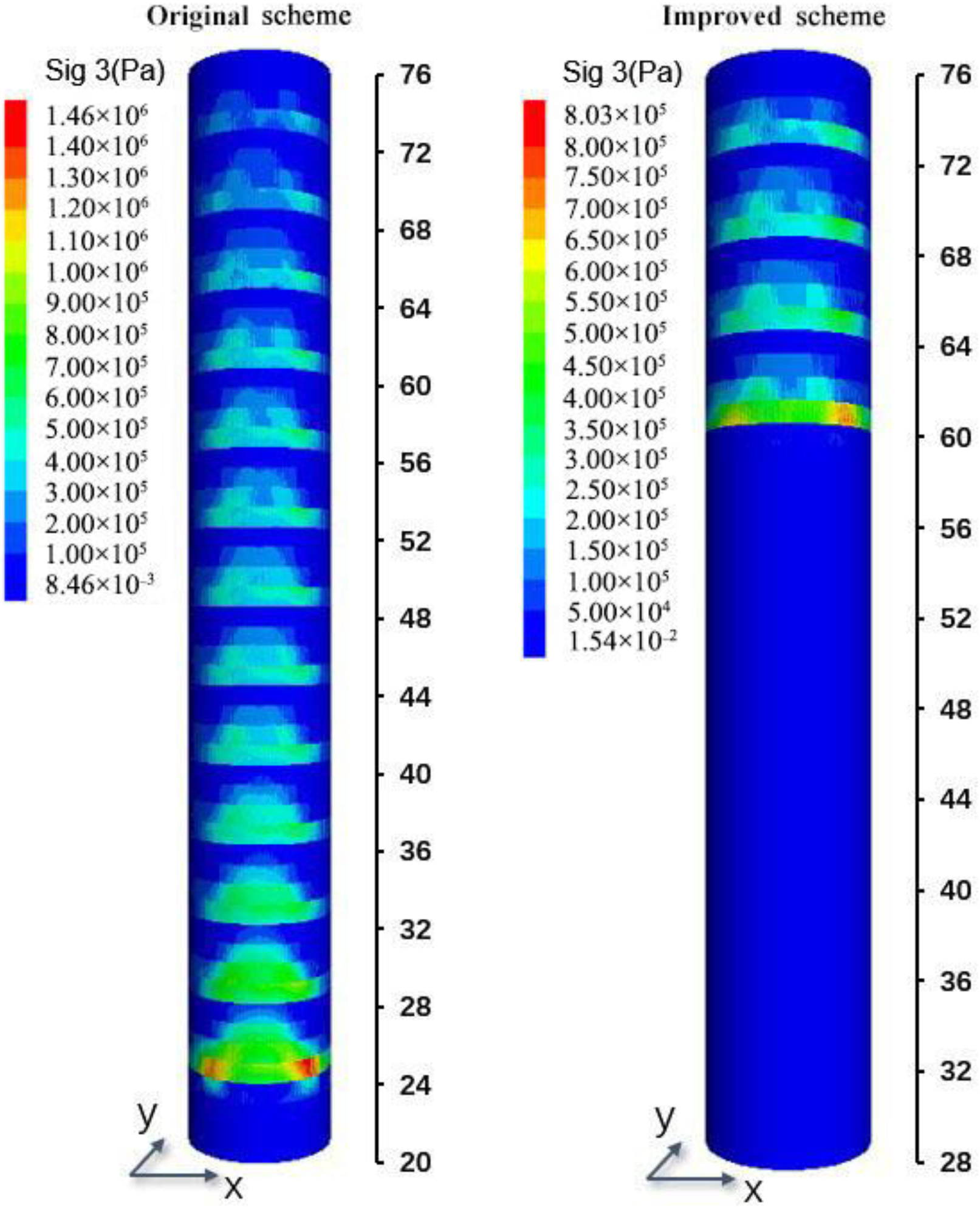
5.2.3. Lining Analysis

According to the modeling calculation, the tangential stress in the lining is the major principal stress, as shown in Figure 16, which shows the stress concentration. The major principal stress in the lining changes longitudinally, as shown in Figure 17. The average magnitude of the major principal stress fluctuation of the original scheme is 23.7 MPa, while that of the proposed scheme is 3.5 MPa, which shows that the proposed scheme can make the stress in the lining more uniform and avoid damage to the lining caused by stress concentration. It is located 40 m away from the working face, which is changed from the original ‘one excavation and one support’ scheme to ‘three excavations and one support’. With the increase in the exposed area of the rock surrounding the shaft, the stress of the shaft lining at this location is more significant than that of the original lining. Therefore, the conversion of the site construction method should be gradually realized to avoid local stress concentrations.
The axial compressive strength of C25 concrete in the shaft lining is 16.7 MPa. According to the value of the major principal stress σ m a x , the safety factor [44] of the lining can be calculated as:
K = σ c c σ m a x
According to the above formula, the compressive safety factor of the original lining is 0.4, which indicates that plastic failure will occur in the original lining. The compressive safety factor of the proposed lining is 2.0, which meets the safety requirements. The minor principal stress contour of the lining is shown in Figure 18.
Figure 17 shows that in the original scheme, there is a large tensile stress in the lining, with a major value of 1.46 MPa, which is located 4 m away from the excavation face. The major tensile stress of the lining in the proposed scheme is 50 kPa. The axial tensile strength of C25 concrete is 1.78 Mpa. According to Formula (3), the safety factor of the lining in the original scheme is 1.2, which is insufficient.

6. Conclusions

This paper presents a deep shaft support method based on the concept of ASGR. The original scheme and the proposed scheme are compared and analyzed from the perspectives of stress, displacement, and plastic zone for the new shaft of the Xincheng Gold Mine. The following main conclusions are drawn.
  • In the original scheme, due to the spatial effect of the excavation face, the surrounding rock stress near the excavation face is not completely released. If lining support is installed very early, the excavation face effect will decrease as the excavation face advances. If the stress of the surrounding rock is not released completely, the displacement of the surrounding rock will be prevented by the lining, which leads to the stress concentration in the lining.
  • Considering the actual stress release tie of the surrounding rock and foreign experience in shaft construction, the support distance is determined to be 12 m, with an interval of three operation cycles.
  • In the proposed scheme, when the lining is 12 m away from the excavation face, the improved support scheme is used for the surrounding rock of the unlined section, which makes the rock surrounding the shaft have enough ties and space to release the stress and displacement. Therefore, the stress distribution in the lining is more uniform, and the lining compressive safety factor is increased to 2.0.

Author Contributions

Data curation, Z.G.; Funding acquisition, X.Z. (Xingdong Zhao); Investigation, X.Z. (Xin Zhou); Methodology, Y.Z.; Writing–review & editing, L.D. All authors have read and agreed to the published version of the manuscript.

Funding

This work was supported by a project of the NSFC Shandong United Fund (U1806208) and the Key projects of National Natural Science Foundation of China (52130403), the Fundamental Research Funds for the Central Universities (N2001033 and N2101022) and the Opening Project of State Key Laboratory of Nickel and Cobalt Resources Comprehensive Utilization. The authors’ special thanks go to CSC (China Scholarship Council) for the scholarship (CSC Student ID: 202106080060).

Conflicts of Interest

All the authors declare that they have no known conflicts of interest that could influence the work reported in this paper.

References

  1. Owens, B. Mining: Extreme prospects. Nature 2013, 495, S4–S6. [Google Scholar] [CrossRef] [PubMed] [Green Version]
  2. Sun, J.; Wang, S. Rock mechanics and rock engineering in China: Developments and current state-of-the-art. Int. J. Rock Mech. Min. Sci. 2000, 37, 447–465. [Google Scholar] [CrossRef]
  3. Jiang, Q.; Su, G.; Feng, X.-T.; Chen, G.; Zhang, M.-Z.; Liu, C. Excavation Optimization and Stability Analysis for Large Underground Caverns Under High Geostress: A Case Study of the Chinese Laxiwa Project. Rock Mech. Rock Eng. 2019, 52, 895–915. [Google Scholar] [CrossRef]
  4. Xie, H.P.; Gao, F.; Ju, Y. Research and Development of Rock mechanics in Deep Ground Engineering. Chin. J. Rock Mech. Eng. 2015, 34, 2161–2178. [Google Scholar] [CrossRef]
  5. Xie, H. Research framework and anticipated results of deep rock mechanics and mining theory. Adv. Eng. Sci. 2017, 49, 1–16. [Google Scholar] [CrossRef]
  6. Foderà, G.; Voza, A.; Barovero, G.; Tinti, F.; Boldini, D. Factors influencing overbreak volumes in drill-and-blast tunnel excavation. A statistical analysis applied to the case study of the Brenner Base Tunnel—BBT. Tunn. Undergr. Space Technol. 2020, 105, 103475. [Google Scholar] [CrossRef]
  7. Yang, J.; Yao, C.; Jiang, Q.; Lu, W. 2D numerical analysis of rock damage induced by dynamic in-situ stress redistribution and blast loading in underground blasting excavation. Tunn. Undergr. Space Technol. 2017, 70, 221–232. [Google Scholar] [CrossRef]
  8. Zhou, Y.-C.; Liu, J.-H.; Huang, S.; Yang, H.-T.; Ji, H.-G. Performance change of shaft lining concrete under simulated coastal ultra-deep mine environments. Constr. Build. Mater. 2019, 230, 116909. [Google Scholar] [CrossRef]
  9. Xue, W.; Yao, Z.; Jing, W.; Tang, B.; Kong, G.; Wu, H. Experimental study on permeability evolution during deformation and failure of shaft lining concrete. Constr. Build. Mater. 2019, 195, 564–573. [Google Scholar] [CrossRef]
  10. Manríquez, A.L.; Sepehrnoori, K. The diffusivity equation for geopressure prediction using well logs. J. Pet. Sci. Eng. 2015, 134, 186–198. [Google Scholar] [CrossRef]
  11. Martyushev, D.A.; Galkin, S.V.; Shelepov, V.V. The Influence of the Rock Stress State on Matrix and Fracture Permeability under Conditions of Various Lithofacial Zones of the Tournaisian–Fammenian Oil Fields in the Upper Kama Region. Mosc. Univ. Geol. Bull. 2019, 74, 573–581. [Google Scholar] [CrossRef]
  12. Martyushev, D. Rock stress state influence on permeability of carbonate reservoirs. Bull. Tomsk Polytech. Univ. Geo Assets Eng. 2020, 331, 24–33. [Google Scholar] [CrossRef]
  13. Wang, J. Calculation of shaft wall stress under negative friction. J. Hefei Univ. Technol. 1995, 18, 117–121. [Google Scholar]
  14. Su, J.; Cheng, Y. Theoretical analysis of additional wellbore force in hydrophobic subsidence formation. Chin. J. Rock Mech. Eng. 2000, 19, 310–313. [Google Scholar]
  15. Su, J. Non-linear mechanical analysis of shaft lining in stratum settlement resulted from water drainage. Chin. J. Rock Mech. Eng. 2005, 24, 139–143. [Google Scholar]
  16. Zhou, Y.; Zhou, G. Strict axisymmetric deformation analysis of shaft linings considering shaft-curing load. Chin. J Geo. Eng. 2008, 30, 170–174. [Google Scholar]
  17. Ozturk, H.; Guler, E. A methodology for lining design of circular mine shafts in different rock masses. Int. J. Min. Sci. Technol. 2016, 26, 761–768. [Google Scholar] [CrossRef]
  18. Brady, B.; Brown, E. Rock Mechanics for Underground Mining; George Allen Unwin: London, UK, 2006. [Google Scholar] [CrossRef]
  19. Zhao, X.; Li, Y. Estimation of support requirement for a deep shaft at the Xincheng Gold Mine, China. Bull. Eng. Geol. Environ. 2021, 80, 6863–6876. [Google Scholar] [CrossRef]
  20. Auld, F. Design of concrete shaft linings. Proc. Inst. Civ. Eng. 1979, 67 Pt 2, 817–832. [Google Scholar] [CrossRef]
  21. Ozturk, H.; Unal, E. Estimation of lining thickness around circular shafts. In Proceedings of the International Mining Congress and Exhibition of Turkey (17th)—IMCET2001, Chamber of Mining Engineers of Turkey, Ankara, Turkey, 22 June 2001; pp. 437–444. [Google Scholar]
  22. He, M. Research progress of deep shaft construction mechanics. J. China Coal Soc. 2021, 46, 726–746. [Google Scholar] [CrossRef]
  23. Yu, Q.; Yin, K.; Ma, J.; Shimada, H. Vertical Shaft Support Improvement Studies by Strata Grouting at Aquifer Zone. Adv. Civ. Eng. 2018, 2018, 5365987. [Google Scholar] [CrossRef]
  24. Ma, F.-S.; Deng, Q.-H.; Cunningham, D.; Yuan, R.-M.; Zhao, H.-J. Vertical shaft collapse at the Jinchuan Nickel Mine, Gansu Province, China: Analysis of contributing factors and causal mechanisms. Environ. Earth Sci. 2012, 69, 21–28. [Google Scholar] [CrossRef]
  25. Hu, X.; He, C.; Walton, G.; Chen, Z. A Combined Support System Associated with the Segmental Lining in a Jointed Rock Mass: The Case of the Inclined Shaft Tunnel at the Bulianta Coal Mine. Rock Mech. Rock Eng. 2020, 53, 2653–2669. [Google Scholar] [CrossRef]
  26. Monteiro, V.M.D.A.; Silva, F.D.A. The use of the Barcelona test as quality control of fiber reinforced shotcrete for underground mining. Constr. Build. Mater. 2020, 262, 120719. [Google Scholar] [CrossRef]
  27. Unrug, K. Construction of Development Openings; Society for Mining, Metallurgy, and Exploration, Inc.: Littleton, CO, USA, 1992. [Google Scholar]
  28. Yang, L.; Yao, Z.; Xue, W.; Wang, X.; Kong, W.; Wu, T. Preparation, performance test and microanalysis of hybrid fibers and microexpansive high-performance shaft lining concrete. Constr. Build. Mater. 2019, 223, 431–440. [Google Scholar] [CrossRef]
  29. Xue, W. Research on Coupled Damage Evolution Mechanism and Strength Characteristics of Shaft Lining Concrete under High Pressure Water; Anhui University of Science and Technology: Huainan, China, 2017. [Google Scholar]
  30. Zhou, X.; He, Z.; Ji, H. Design method of freezing rock wall under high water pressure. J. China Coal Soc. 2011, 36, 2121–2126. [Google Scholar]
  31. Huang, W.; Wang, X.; Shen, Y.; Feng, F.; Wu, K.; Li, C. Application of concrete-filled steel tubular columns in gob-side entry retaining under thick and hard roof stratum: A case study. Energy Sci. Eng. 2019, 7, 2540–2553. [Google Scholar] [CrossRef] [Green Version]
  32. Zhao, Z.; Sun, W.; Chen, S.; Yin, D.; Liu, H.; Chen, B. Determination of critical criterion of tensile-shear failure in Brazilian disc based on theoretical analysis and meso-macro numerical simulation. Comput. Geotech. 2021, 134, 104096. [Google Scholar] [CrossRef]
  33. Vergne, J. The Hard Rock Miner’s Handbook, 3rd ed.; McIntosh Engineering Limited: North Bay, ON, Canada, 2003. [Google Scholar]
  34. Cai, M.; Brown, E.T. Challenges in the Mining and Utilization of Deep Mineral Resources. Engineering 2017, 3, 432–433. [Google Scholar] [CrossRef]
  35. Hu, Y.; Li, W.; Wang, Q.; Liu, S. Vertical Shaft Excavation Shaping and Surrounding Rock Control Technology Under the Coupling Action of High Ground Stress and Fracture Formation. J. Perform. Constr. Facil. 2020, 34, 04020116. [Google Scholar] [CrossRef]
  36. Mu, W.; Wang, D.; Li, L.; Yang, T.; Feng, Q.; Wang, S.; Xiao, F. Cement flow in interaction rock fractures and its corresponding new construction process in slope engineering. Constr. Build. Mater. 2021, 303, 124533. [Google Scholar] [CrossRef]
  37. Ostrowski, W. Design considerations for modern shaft linings. Can. Min. Metall. Bull. 1972, 65, 58–72. [Google Scholar]
  38. Zhao, X.; Li, Y.; Zhang, S.; Chen, Y.; Wang, C.; Wang, X. Analysis and application of disturbance stress reaction mechanism of surrounding rock during sinking ultra-deep shaft. Hazards Control Tunn. Undergr. Eng. 2020, 2, 19–28. [Google Scholar]
  39. Barton, N.; Lien, R.; Lunde, J. Engineering classification of rock masses for the design of tunnel support. Rock Mech. Rock Eng. 1974, 6, 189–236. [Google Scholar] [CrossRef]
  40. Grimstad, E.; Barton, N. Updating the Q-system for NMT. In Proceedings of the International Symposium on Sprayed Concrete-Modern Use of Wet Mix Sprayed Concrete for Underground Support, Fagemes, Oslo, Norway, 22–26 October 1993; pp. 46–66. [Google Scholar]
  41. Barton, N. Some new Q-value correlations to assist in site characterization and tunnel design. Int. J. Rock Mech. Min. Sci. 2002, 39, 185–216. [Google Scholar] [CrossRef]
  42. Bieniawski, Z. Engineering classification of jointed rock masses. Civ. Eng. S. Afr. 1973, 15, 333–343. [Google Scholar]
  43. Bieniawski, Z. Engineering Rock Mass Classifications; Wiley: New York, NY, USA, 1989. [Google Scholar]
  44. Hormazabal, E.; Soto, C.; Russo, A.; Carranza-Torres, C. Estimation of support requirement for large diameter ventilation shaft at Chuquicamata underground mine in Chile. In Proceedings of the Harmonising Rock Engineering and the Environment—12th ISRM International Congress on Rock Mechanics, Beijing, China, 18–21 October 2011; pp. 1511–1520. [Google Scholar] [CrossRef]
Figure 1. Sequence of operations while sinking through normal ground conditions.
Processes 10 01376 g001
Figure 2. Mechanical model induced by shaft sinking under unequal confining pressures. (R0 is shaft radius; P0 is the vertical stress of the shaft; σ θ is tangential stress; σ r is radial stress; λ is the ratio of horizontal stress).
Processes 10 01376 g002
Figure 3. Stress of the longitudinal section from ASGR. ((a) is the longitudinal section stress curve of ASGR; (b) is the schematic diagram of ASGR releasing stress by increasing the distance between the lining and driving face).
Processes 10 01376 g003
Figure 4. Induced stress reaction distribution of the surrounding rock by shaft sinking [38].
Processes 10 01376 g004
Figure 5. Borehole histogram of ZCK−1.
Processes 10 01376 g005
Figure 6. Elastoplastic numerical simulation results of the shaft rock at −1276 m. (a) Contour of major principal stress. (b) Contour of maximum displacement. (c). Contour of plastic zone of wall rock.
Processes 10 01376 g006aProcesses 10 01376 g006b
Figure 7. Scheme of primary support.
Processes 10 01376 g007
Figure 8. Schematic diagram of ASGR.
Processes 10 01376 g008
Figure 9. Calculation process of the original excavation plan.
Processes 10 01376 g009
Figure 10. Calculation process of the proposed excavation plan.
Processes 10 01376 g010
Figure 11. Calculation model of shaft excavation and support.
Processes 10 01376 g011
Figure 12. Major principal stress for different support construction schemes.
Processes 10 01376 g012
Figure 13. Major principal stress contrast of shaft. (a) Vertical section of the shaft. (b) Cross section of the shaft.
Processes 10 01376 g013
Figure 14. Ground displacement of different support construction schemes.
Processes 10 01376 g014
Figure 15. Longitudinal deformation profile of the shaft.
Processes 10 01376 g015
Figure 16. Major principal stress on the lining.
Processes 10 01376 g016
Figure 17. Major principal stress curve for the lining.
Processes 10 01376 g017
Figure 18. Minor principal stress on the lining.
Processes 10 01376 g018
Table 1. Correlation between RQD and rock quality at different depths.
Depth/mLithologyRQDRock Quality
−930~−987Cataclastic Granodiorite83%Good
−987~−1101Granodiorite, Semicataclastic Granodiorite and Cataclastic Granodiorite55%Fair
−1101~−1167Granodiorite81%Good
−1167~−1199Granodiorite71%Fair
−1199~−1254Granodiorite87%Good
−1254~−1276Semicataclastic Granodiorite59%Fair
Table 2. Number of joint sets at different depths.
Depth/mNumber of Joint Sets
−930.00~−972.002~3
−972.00~−987.003
−987.00~−1050.003
−1050.00~−1073.003
−1073.00~−1102.003
−1102.00~−1153.002
−1153.00~−1207.003
−1207.00~−1250.002
−1250.00~−1271.003
Table 3. Intact rock mean parameters.
RockDensity g/cm3UCS/MPac/MPaφ/°E/GPa μ
Granite2.66102.524.349.9470.80.29
Table 4. The evaluation results of Barton rock mass quality (Q) classification.
Depth/mRQDJnJrJaJwSRFQRock RatingRock Quality
−930.0~−972.08661~1.511.0201.1poor
−972.0~−987.07691~1.511.0200.6poor
−987.0~−1050.05191~1.511.0200.4poor
−1050.0~−1073.07161~1.511.0200.9poor
−1073.0~−1102.05261~1.511.0200.7poor
−1102.0~−1153.08061~1.511.0201poor
−1153.0~−1207.07791~1.511.0200.6poor
−1207.0~−1250.08791~1.511.0200.7poor
−1250.0~−1271.06891~1.511.0200.6poor
Table 5. Classification results of rock mass quality based on RMR.
Depth/mUCS/MPaRQDSpacing/mJoint ConditionGround WaterRevisionScoreRock RatingRock Quality
−930.0~−972.01217102515−574good
−972.0~−987.01217102515−574good
−987.0~−1050.01213102515−570good
−1050.0~−1073.01213102515−570good
−1073.0~−1102.0121382515−568good
−1102.0~−1153.01217102515−574good
−1153.0~−1207.0121782515−572good
−1207.0~−1250.01217102515−574good
−1250.0~−1271.01213102515−570good
Table 6. Estimation results of rock mass strength parameters.
Depth/mc/MPaφ/° σ c m a s s / MPa σ t m a s s / MPa Em/GPa
−930.0~−972.07.2839.6110.500.22420.73
−972.0~−987.06.5537.087.160.14116.12
−987.0~−1050.06.5537.087.160.14116.12
−1050.0~−1073.06.5537.087.160.14116.12
−1073.0~−1102.06.5537.087.160.14116.12
−1102.0~−1153.06.5537.087.160.14116.12
−1153.0~−1207.06.5537.087.160.14116.12
−1207.0~−1250.06.5537.087.160.14116.12
−1250.0~−1271.06.5537.087.160.14116.12
Publisher’s Note: MDPI stays neutral with regard to jurisdictional claims in published maps and institutional affiliations.

