Article

On the Microcrack Propagation and Mechanical Behavior of Granite Induced by Thermal Cycling Treatments

1
State Key Laboratory of Coal Resources and Safe Mining, China University of Mining and Technology, Xuzhou 221116, China
2
School of Mines, China University of Mining and Technology, Xuzhou 221116, China
3
State Key Laboratory for Geomechanics and Deep Underground Engineering, China University of Mining and Technology, Xuzhou 221116, China
4
School of Civil and Mechanical Engineering, Curtin University, Perth, WA 6000, Australia
*
Author to whom correspondence should be addressed.
Processes 2022, 10(8), 1551; https://doi.org/10.3390/pr10081551
Submission received: 21 July 2022 / Revised: 2 August 2022 / Accepted: 2 August 2022 / Published: 7 August 2022

Abstract

:
Deep geothermal energy is a renewable and environmentally friendly resource, and the hot dry rock in a geothermal reservoir is subjected to thermal cycling treatment. Thermal cycling treatment can cause thermal stresses in the rock matrix and result in thermal cracking, which significantly influence the physical and mechanical properties of a rock. To investigate the influence of thermal cycling treatment on the microcrack propagation and mechanical behavior of a granite rock, a series of physical and mechanical tests were performed on nontreated and treated granite samples. The testing results show that the mass, density, and P-wave velocity of granite decrease with heating temperature and cycling time increase, while the volume of the samples increases significantly. The UCS and elastic modulus of the granite declined from 178.65 MPa and 20.09 GPa to 24.58 MPa and 3.81 GPa after treatment at 500 °C for 30 thermal cycling times, respectively. The degradation trends of the UCS and the elastic modulus of the granite can be characterized by the heating temperature and the thermal cycling times. High temperature and frequent thermal cycling treatment can induce microcrack propagation within the granite, which causes the failure of the samples and leads a transformation of granite from brittleness to ductility.

1. Introduction

Renewable and reliable resources, such as deep geothermal and nuclear energy [1,2], have attracted a large amount of concern for their clean, financial, and environmentally friendly advantages over traditional fossil energy sources, such as gas, oil, and coal [3,4,5]. Generally, hot dry rock (HDR) geothermal energy, at a more than 2 km depth and with more than 180 °C, has a large reserve and wide distribution and presents a potential exploitation capability [6,7,8]. During the construction of deep wells to form an artificial reservoir, a large amount of cold drilling fluid will contact HDR directly [9]. Meanwhile, in the extraction process, water or another appropriate fluid with low temperature is injected and circulated through the HDR and eventually pumped back with a production temperature of 150 to 380 °C to a power station on the surface to produce electricity [10,11]. Therefore, the HDR will experience a series of frequent temperature changes during the exploitation of geothermal energy [12]. Frequent thermal cycling treatment can induce thermal gradient and thermal cracking in the HDR, which exhibits a significantly different physical property and mechanical behaviors compared with those under the original state [13,14,15,16,17]. Furthermore, the engineering stability of the artificial reservoir is highly influenced by the thermal cycling treatment.
So far, plenty of studies have been conducted to investigate the influence of thermal cycling treatment on the physical and mechanical properties of rocks. Yuan et al. [18] experimentally investigated the temperature change and acoustic emission characteristics of granite during the heating and air-cooling processes. The authors reported that the cumulative acoustic emission count during the air-cooling process is significantly smaller than that during the heating process, which indicates that the heating treatment can produce more serious damage to the rocks than the air-cooling treatment. Elgiarib et al. [19] conducted a series of physical and mechanical experiments on granodiorite rock to investigate the influence of high-temperature treatment. The authors suggested that the thermal damage threshold of the testing rock is 400 °C, and the mechanical response of the granodiorite rock induced by the temperature shifts from a stable to an unstable state. Qian et al. [20] performed conventional triaxial compression tests on granite rock after high-temperature heating and water quenching cycling treatment and found that the longitudinal wave velocity and bulk density of the granite rocks present a negative correlation with the heating temperature and water quenching cycling times. When heated before the thermal threshold (450 °C), the peak strength of the granite rock decreased linearly, and the peak axial strain exhibited an exponential increasing trend. Zhao et al. [21] experimentally investigated the mechanical properties and energy characteristic of granite rock induced by high temperature and increasing amplitude cyclic loading treatment. The authors suggested that the granite rocks show an evident observation of rock hardening characteristic after being subjected to high temperature and cyclic loads, and the energy evolution of granite rocks reverses from a nonlinear to a linear feature with increasing temperature. Sun et al. [22] conducted conventional tensile strength tests on diorite rocks subjected to different heating–cooling cycles at different temperatures. The authors reported that when heated at 400 °C, granite rock experiences a serious damage induced by the loss of combined water and thermal tensile stresses. Vagnon et al. [23] conducted a series of laboratory tests on marble rocks subjected to thermal cycles to evaluate the variation of the physical and mechanical properties of rocks. The authors suggested that the degradation of the physical and mechanical properties of rocks is mainly due to the increase in crack density and porosity and proposed a damage parameter to quantify the degradation of mechanical properties. Wu et al. [24] experimentally studied the effect of cyclic heating and liquid nitrogen cooling on the physical and mechanical properties of granite rocks and developed an improved deterioration model to describe the integrity loss of granite during cycles. Villarraga et al. [25] researched the effect of thermal cycles on the mechanical response of limestone rocks and found that the accumulation of strains, P-wave velocity, and uniaxial compression strength decrease with thermal cycle increase, while no noticeable change in porosity are observed. Rong et al. [26] carried out research in the evaluation of the physical and mechanical behaviors of rocks in the process of thermal cycling at a high temperature. The authors reported that the P-wave velocity, characteristic stress, and elastic modulus decrease when the thermal cycle times increase. Meanwhile, more fragments are observed in rocks subjected to more thermal cycles, and the integrity is lower than that treated with fewer thermal cycles.
When subjected to thermal cycling treatment, rocks will create thermally induced microcracks due to the generation of the thermal gradient, which is induced by the expansion or contraction of individual particles in contact with other particles reaching the tensile or shear strength of the rock [27,28]. The propagation of the microcracks influences the physical properties and mechanical behavior of rocks significantly. However, the mechanism contributes to microcrack behaviors, and the physical–mechanical properties of rocks may not be sufficiently illustrated. In this research, the influence of thermal cycling treatment, at different heating temperatures for various thermal cycling times, on microcrack propagation and the mechanical behavior of granite rock is experimentally investigated. Before the thermal cycling treatment, a series of basic physical properties (i.e., mass, volume, and P-wave velocity) of granite samples were measured, and the mineral composition of the testing granite rock was obtained by using X-ray diffraction (XRD). After a muffle furnace applied the thermal cycling treatment on the granite samples, the aforementioned physical properties of the granite samples were measured again. Then, a scanning electron microscope (SEM) was used to analyze the microcrack propagation of the granite rock induced by the thermal cycling treatment. Finally, the mechanical performance and failure mode of the treated granite rock were investigated by using a rigid servo-controlled triaxial compression test system.

2. Experimental Material and Methodology

2.1. Specimen Preparation

The specimens used in this research are granite, which is a typical igneous rock formed in the magmatism process. A granite block was mined from Hubei Province, China. Following the specification recommended by the International Society for Rock Mechanics (ISRM), the cylindrical granite specimens were cored with 50 mm diameter and 100 mm height from an identical block to minimize the scatter of the testing results [29,30]. Meanwhile, sample ends were carefully ground and polished by a grinding machine until the deviation ranges of the flatness and roughness were less than 0.5 mm and 0.05 mm, respectively. Prior the thermal treatment, all the specimens were heated at 45 °C for 48 h in a dry oven and cooled to room temperature naturally to eliminate the influence of moisture. Subsequently, the mineralogical compositions of the granite were determined by X-ray diffraction (XRD) analysis, which indicated that the granite mainly consists of 40.6% quartz, 26.1% albite, 15.5% microcline, and 13.2% muscovite, as shown in Figure 1.

2.2. Physical Property Tests

Three basic physical tests, which were mass measurement, volume determination, and P-wave velocity tests, were conducted on all the cylindrical samples before and after thermal cycling treatments for comparison. The specimen volumes were calculated from the recorded values by a conventional caliper. A balance with a capability of weighing to an accuracy of 0.01 g was utilized to capture the mass of the specimen. The density was obtained from the ratio of the specimen mass to the specimen volume. Moreover, the P-wave velocity tests were taken along the sample axis using an ultrasonic measure instrument. Some Vaseline was daubed between the transducers and the sample surface to provide a good acoustic coupling, and a small load of about 6 N was applied to improve the contact and reproducibility. Additionally, granite specimens with a P-wave velocity significantly deviating from the average value were excluded to reduce the influence of the discreteness of the rock samples on the testing results.

2.3. Microcrack Observation

Scanning electron microscope (SEM) technology was utilized to investigate the microcrack propagation within the samples subjected to the thermal cycling treatment. After thermal cycling treatment, thin sections with a thickness of approximately 30 mm were made, from which SEM images were obtained to observe the development of the microcracks by using an SU8020 SEM system. In addition, the SEM system used in this research operated at a 24 kV accelerating voltage in a high-vacuum mode. Meanwhile, thin sections of thermal-cycling-treated granite samples were coated with gold to ensure that microcracks can be observed directly and conveniently by SEM.

2.4. Thermal Cycling Procedure

Thermal cycling treatments were administered to the granite samples according to the following procedure.
  • The dry samples were heated in a muffle furnace from room temperature (23 °C) to the predefined temperature, which varied from 100 to 500 °C, at intervals of 100 °C. The heating rate was controlled at 2 °C to avoid potential temperature gradients and thermal shock within the sample. In addition, after reaching the target temperature, the samples were held isothermally in the furnace for more than 2 h to ensure temperature uniformity.
  • The heated samples were taken out of the furnace and exposed naturally to the open atmosphere until reaching room temperature. This cooling treatment allowed the samples to cool with a gentle cooling rate. At this point, one thermal cycling treatment was complete.
  • Four levels of thermal cycles (i.e., 1, 10, 20, and 30) were set in this study to investigate the influence of thermal cycling times on the microcrack propagation and mechanical behaviors of granite rock. Subsequently, the aforementioned physical property tests and SEM were conducted on the granite samples after each of the five thermal cycles finished.

2.5. Mechanical Property Tests

Conventional UCS tests were performed by an MTS-4000 rigid servo-controlled triaxial compression test system with a loading capacity of 2200 KN (as shown in Figure 2f). The compression test system could make real-time recording of the axial displacement. The samples subjected to different thermal cycling treatments were deformed to failure at a displacement control rate of 0.2 mm/min.
Figure 2 illustrates the complete testing scheme and the instruments used in this study. To avoid discreteness of test results as much as possible, all the thermal treatment and mechanical tests of the granite in each scenario were repeated three times, and the test results in the study were expressed as a mean value.

3. Results

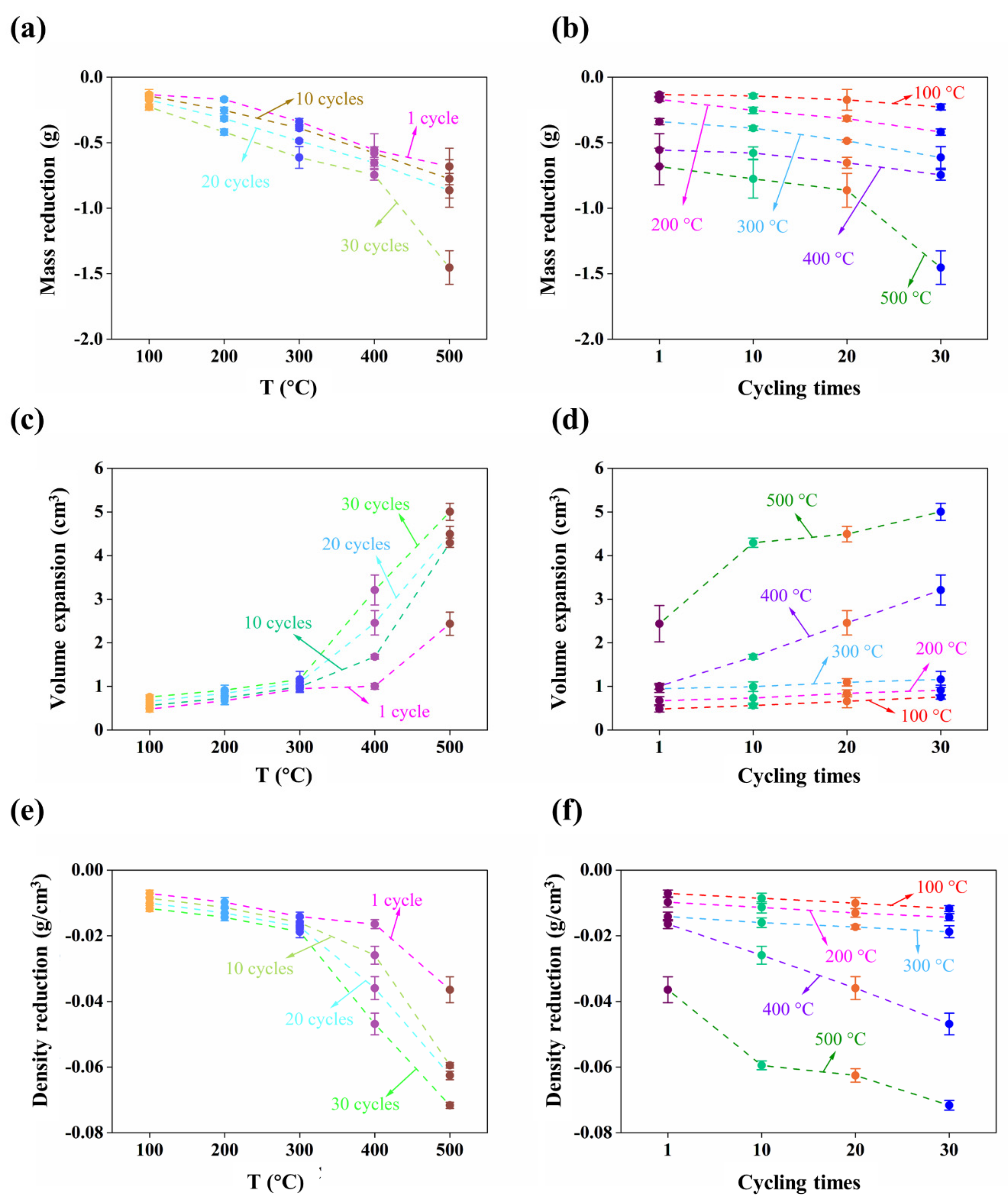
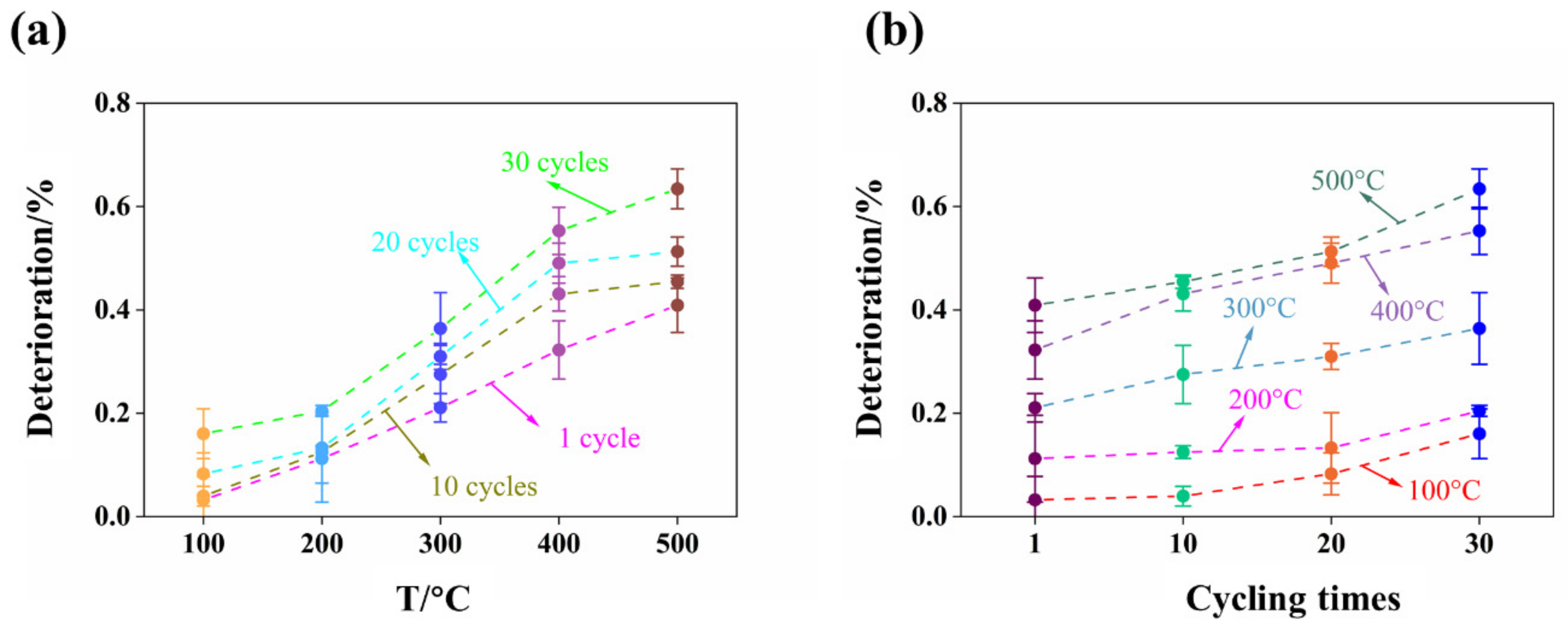
3.1. Mass, Volume, and Bulk Density

Table 1 lists the mass, volume, and bulk density of the granite samples induced by the predeterminated thermal cycling treatment. To illustrate the variation trends intuitively and clearly, the deviation values of the mass, volume, and density of the granite were carefully calculated and are shown in Figure 3. It was easily observed that the mass and density of the granites decrease with the treated temperature and cycling times increase, while the volume of the samples increases. Additionally, the maximum mass reduction of granite is about 0.28% when treated by 30 thermal cycling times at 500 °C, while the mass reduction of granite is only 0.13% when treated by 1 thermal cycling time at 100 °C. The main reason for the mass reduction of granite during thermal treatment is water evaporation. Minerals in the rock present various water evaporation reactions at different temperature intervals. Generally, when the heating temperature is approximately 100 °C, the bound water could evaporate from the surface of the sample and the pores between the minerals in the granite rock. Moreover, when the heating temperature reaches 400 °C, the crystal water could escape from the constraint of the mineral lattice. Therefore, after being frequently treated by high temperature, the mass of the granite rock could significantly decrease.
The volume of the rock is a convenient and intuitive index to assess its compactness. As shown in Figure 3b,d, after being heated at 500 °C for 30 cycling times, the granite rock expands from 199.63 to 204.64 cm3 in average volume, and the increase rate of the volume is approximately 2.51%. Furthermore, the minerals within the granite rock could expand in the thermal cycling treatment process, while the different minerals could expand in different rates when subjected to the same thermal treatment. The nonuniform expansions between different minerals could result in microcracks in the granite rock. The details of microcrack propagation will be investigated in the following section.
Density is one of the most commonly used indicators of rock, which is influenced by the mass and volume of the samples. Figure 3c,d shows that the density of the granite rock decreases with the heating temperature and treatment time increase. Specifically, after being heated at 500 °C for 30 cycling times, the density of the granite rock decreases from 2.639 to 2.568 g/cm3 in average density, and the decrease rate of the density is about 2.71%.
Additionally, before the thermal cycling treatment, all the samples were fully dried, which means that free water was avoided in the granite rock. Therefore, the escaping water induced by the thermal cycling treatment are bound water and structural water, whose masses are relatively small. As a result, the density variation of the granite rock subjected to the thermal cycling treatment is mostly and significantly influenced by the changes of volume.

3.2. Ultrasonic Wave Propagation

An ultrasonic wave test, especially the P-wave velocity test, is a frequently used method to assess the structural integrity of a rock. Figure 4 illustrates the deterioration rates of the P-wave velocity of the granite rock subjected to thermal cycling treatment, and the detailed measurement data of the P-wave velocity are listed in Table 2. Based on the results of the ultrasonic wave test before thermal cycling treatment, the average P-wave velocity of the original standard granite samples is 4109 m/s, which indicates that the granite samples used in this research are intact in the natural state. Generally, when the heating temperature and thermal cycling treatment times increase, the P-wave velocity of the granite samples decreases monotonically, which implies that plenty of microcracks generated in the granite rock are induced by high temperature and frequent treatment times. Specifically, the P-wave velocity of the granite rock significantly decreases from 3972 to 1453 m/s on average after being heated at 500 °C for 30 times, and the average rate of decrease in P-wave velocity is 63.42%. The decreases in P-wave velocity in the granite rock are mainly attributed to the generation of microcracks during the thermal cycling treatment. Therefore, the P-wave velocity test can be used to characterize thermal cracks generated in the rocks and quantify the overall damage degree.

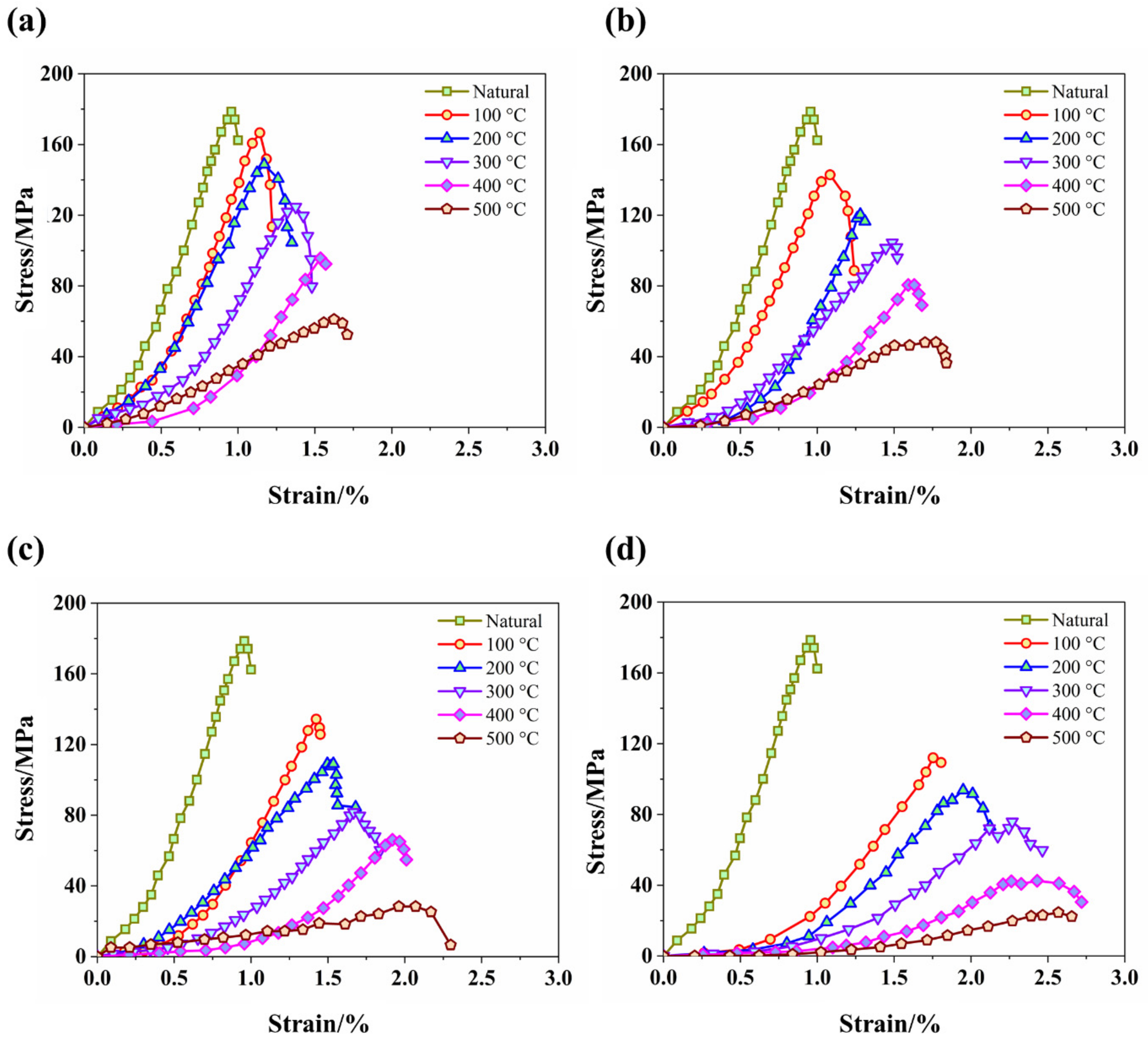
3.3. Stress–Strain Curves

Figure 5 shows the complete stress–strain curves of the granite rock subjected to thermal cycling treatment. It is easily observed that the natural granite rocks present a significant brittleness behavior with a sharp postpeak softening response at small axial strains. Generally, the complete stress–strain curve of all granite samples subjected to thermal cycling treatment can be divided into four stages: closure stage, liner elastic stage, yield stage, and postpeak stage. It can be easily observed that the stress–strain curves of all the granite rocks present a concave-upward shape from initial loading, which is mainly due to the closure of the natural microcracks. Meanwhile, the initial nonlinear deformation stage becomes more and more evident with the heating temperature and treatment time increase. The main reason for the reaction are the massive thermal cracks generated induced by thermal cycling treatment. Then, as the load is continuously applied, the samples are deformed elastically, which means that the stress increases approximately linearly with increasing strain. Specifically, the slopes of the stress–strain curves of the granite rocks decrease gradually with the heating temperature and treatment time increase. After thermal cycling treatment, the yield stage of the granite rock is lengthened, and the stress–strain curves turn smoothly. When the load exceeds the bearing capacity of the granite rock, the stress–strain curves collapse immediately.

3.4. UCS and Elastic Modules

UCS and elastic modules are two of the best parameters for assessing the mechanical property of rocks. The calculated results of the granite rocks after thermal cycling treatment are listed in Table 3. It is clearly and intuitively obtained that the UCS and the elastic modules of the granite rock both decrease with the heating temperature and treatment time increase. Furthermore, Figure 6a,b shows the variation feature of the UCS and elastic modules of the granite rock induced by thermal cycling treatment. In addition, based on the regression analysis, the UCS and elastic modules can be characterized by the heating temperature and the cycling times as follows:
σ = 0.244 x 1.668 y + 191.902
E = 0.271 x 0.022 y + 21.531
where σ , E , x , and y are UCS, elastic modules, heating temperature, and thermal times, respectively. Meanwhile, the fitting factors of the UCS and the elastic modules are 0.983 and 0.969, respectively.

4. Discussion

4.1. Microcrack Propagation
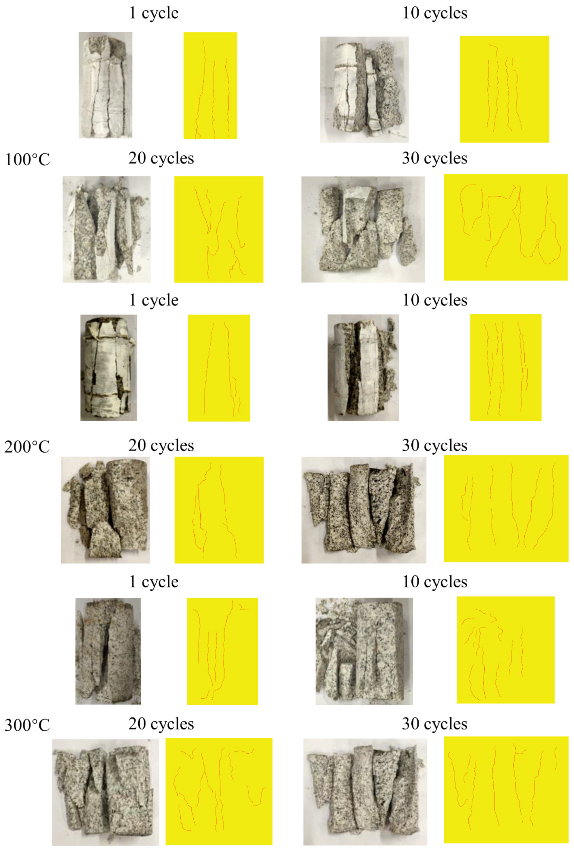
Figure 7 shows SEM images of the granite rocks induced by the thermal cycling treatment. Intergranular cracks that exist between the particle boundaries and transgranular cracks, which are generated within the mineral particles, can be observed, and the patterns of the microcracks are signed by arrows in the figure. It can be easily obtained that the particles of the granite rock are smooth and arrayed closely. Furthermore, the granular borders of the quartz and albite became clearer, and merely intergranular cracks were produced in the samples when the granite rock was subjected to a 100 °C temperature for 10 thermal cycling times. Compared with that treated at a low temperature (below 200 °C), the density of the intergranular cracks grows gradually, and transgranular cracks occur within the quartz, albite, and microcline particles in the granite rock when the treating temperature is higher than 300 °C. After being treated at 400 °C, the transgranular cracks develop from the boundary of the granite to the center and attract each other to form microcrack networks. The reaction illustrates that the thermal cycling treatment can induce not only intergranular cracks but also transgranular cracks in the granite rock. Specifically, when the granite rock is treated at 500 °C for 30 thermal cycling times, a microcrack network consists of several intergranular cracks, and transgranular cracks are formed to induce microdamage and mechanical performance degradation, which could lead to the failure of the samples. Generally, the intergranular cracks and transgranular cracks within the granite rock that were subjected to high temperature and frequent thermal cycling treatment were abundant in quantity and evidenced in shape. It indicates that the granite rock subjected to higher temperature and more frequent thermal cycling treatment were more prone to degradation and damage, which can be explained by the fact that the temperature gradient and thermal shock were more intense under higher temperature and more frequent thermal cycling treatment condition.

4.2. Failure Mode

The macrofracture of rocks is mainly due to the expansion and propagation of internal microcracks. Thermal cycling treatment of the granite rock influences the morphology of the microcracks and results in various macrofracture networks and different types of failure modes. Figure 8 presents the macrofractures and geological sketches of the granite samples subjected to thermal cycling treatment. In general, the granite rock is a typically brittle material and presents a multiple axial splitting tensile failure mode under UCS tests. However, when the granite rock is subjected to thermal cycling treatment, the density of the macrofractures gradually grows, and the failure mode is transformed from axial splitting to shear failure, which indicates that the granite rock experienced a tendency to transition from brittleness to ductility. This transition is highly influenced by the mineral composition and heterogeneity of the granite rock. In addition, the integrity of the granite samples treated over 300 °C is significantly lower than that of samples subjected to temperatures below 200 °C, and it can be easily observed that shear failure occurs when the samples are treated at 400 °C. Furthermore, when the granite rock is treated at 500 °C for 30 cycling times, several typical double “Y” dominant macrofractures can be observed in the samples, and the failure mode completely transforms to shear failure. Moreover, the failure surface is significantly irregular, and the drop is basically powdery, which indicates that the granite rock is seriously damaged by thermal cycling treatment.

5. Conclusions

In this study, a series of physical and mechanical tests were performed on granite samples to investigate the microcrack propagation and mechanical behaviors of granite rocks induced by thermal cycling treatment. Research results yielded the following conclusions:
(1)
The mass, volume, and P-wave velocity of the granite rock subjected to thermal cycling treatment are significantly influenced by the treated temperature and thermal cycling times. When the granite rocks are subjected to higher temperature and more frequent thermal cycling treatment, the mass, density, and P-wave velocity of the samples decrease more seriously, while the volume of the samples increases significantly.
(2)
The mechanical property of the granite rocks is highly influenced by thermal cycling treatment. The UCS and elastic modulus of the granite samples both present a negative relationship with the treated temperature and thermal cycling times. The UCS and elastic modulus of the granite declined from 178.65 MPa and 20.09 GPa to 24.58 MPa and 3.81 GPa after being treated at 500 °C for 30 thermal cycling times, respectively. Additionally, the UCS and elastic modulus of the granite samples subjected to thermal cycling treatment can be characterized by the heating temperature and the thermal cycling times.
(3)
Both intergranular cracks and transgranular cracks can be observed in the granite rock after thermal cycling treatment by SEM. Moreover, transgranular cracks can be produced in the granite rock by high temperature and frequent thermal cycling treatment. The temperature gradient and thermal shock induced by thermal cycling treatment are the main reason for the microcrack propagation within the samples and the degradation of the mechanical performance of the granite rocks.
(4)
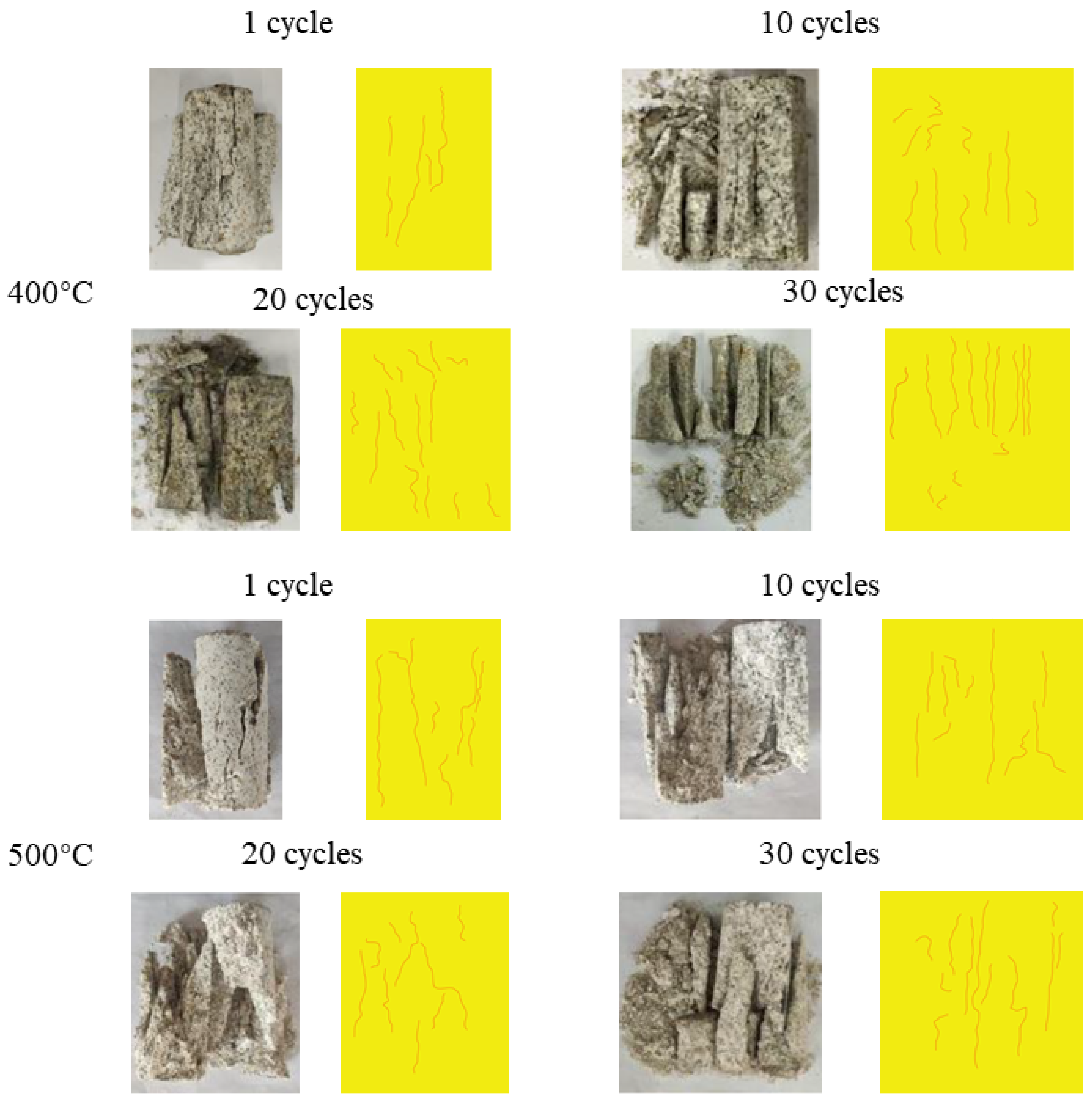
Thermal cycling treatment can significantly influence the macrofracture network in the samples and the failure mode of the granite rocks under uniaxial compression loads. After the granite rocks are subjected to high temperature and frequent thermal cycling treatment, the density of the macrofracture network grows gradually, and the failure mode of the granite samples is transformed from axial splitting to shear failure. In addition, the property of the granite rocks can be reversed from brittleness to ductility.

Author Contributions

Methodology, X.-W.Z. and D.L.; investigation, L.S.; data curation, Y.C.; writing—original draft preparation, L.S.; writing—review and editing, Y.C. and D.L.; visualization, X.-W.Z.; supervision, J.-H.X. and F.S.; project administration, X.-W.Z.; funding acquisition, J.-H.X. All authors have read and agreed to the published version of the manuscript.

Funding

This research was funded by [the Independent Research Project of State Key Laboratory of Coal Resources and Safe Mining, CUMT] grant number [SKLCRSM001] And [the Key projects of the Joint Fund of the National Natural Science Foundation of China] grant Number [U21A20107].

Institutional Review Board Statement

Not applicable.

Data Availability Statement

The data used to support the findings of this study are included within the article. Informed consent was obtained from all subjects involved in the study. Written informed consent has been obtained from the patient(s) to publish this paper.

Acknowledgments

This paper was supported by the Independent Research Project of State Key Laboratory of Coal Resources and Safe Mining, CUMT and the Key Projects of the Joint Fund of the National Natural Science Foundation of China.

Conflicts of Interest

The authors declare that they have no conflicts of interest.

References

  1. Oettingen, M.; Skolik, K. Numerical design of the Seed-Blanket Unit for the thorium nuclear fuel cycle. E3S Web Conf. 2016, 10, 00067. [Google Scholar] [CrossRef] [Green Version]
  2. Oettingen, M.; Cetnar, J. Numerical modelling of modular high-temperature gas-cooled reactors with thorium fuel. Nukleonika 2021, 66, 133–138. [Google Scholar] [CrossRef]
  3. Zhang, Y.; Zhao, G.-F. A Global Review of Deep Geothermal Energy Exploration: From a view of Rock Mechanics and Engineering. Geomech. Geophys. Geo-Energy Geo-Resour. 2020, 6, 4. [Google Scholar] [CrossRef]
  4. Gamboa, M.; Iribarren, D.; Dufour, J. On the Environmental Suitability of High- and Low-enthalpy Geothermal Systems. Geothermics 2015, 53, 27–37. [Google Scholar] [CrossRef]
  5. Duchane, D.V. Geothermal Energy from Hot Dry Rock: A Renew able Energy Technology Moving towards Practical Implementation. Renew. Energy 1996, 9, 1246–1249. [Google Scholar] [CrossRef]
  6. Jasmin, R.; Hubert, L.; Antonie, C.; Malo, M. Temperature Dependence of Rock Salt Thermal Conductivity: Implications for Geothermal Exploration. Renew. Energy 2022, 184, 26–35. [Google Scholar]
  7. Tomac, I.; Sauter, M. A Review on Challenges in the Assessment of Geomechanical Rock Performance for Deep Geothermal Reservoir Development. Renew. Sustain. Energy Rev. 2018, 82, 3972–3980. [Google Scholar] [CrossRef]
  8. Kuriyagawa, M. Hot Dry Rock Geothermal Energy Development Project at Los Alamos, USA. J. Geotherm. Res. Soc. Jpn. 1984, 6, 87–99. [Google Scholar]
  9. Zhao, Y.; Feng, Z.; Xi, B.; Wan, Z.; Yang, D.; Liang, W. Deformation and Instability Failure of Borehole at High Temperature and High Pressure in Hot Dry Rock Exploitation. Renew. Energy 2015, 77, 159–165. [Google Scholar] [CrossRef]
  10. Feng, C.; Wang, H.; Jing, Z. Investigation of Heat Extraction with Flowing CO2 from Hot Dry Rock by Numerical Study. Renew. Energy 2021, 169, 242–253. [Google Scholar] [CrossRef]
  11. Chen, Y.; Zhao, Z.; Peng, H. Convective Heat Transfer of Water Flow in Intersected Rock Fractures for Enhanced Geothermal Extraction. J. Rock Mech. Geotech. Eng. 2022, 14, 108–122. [Google Scholar] [CrossRef]
  12. Isaka, B.L.A.; Gamage, R.P.; Rathnaweera, T.D.; Perera, M.S.A.; Chandrasekharam, D.; Kumari, W.G.P. An Influence of Thermally-Induced Micro-Cracking under Cooling Treatments: Mechanical Characteristics of Australian Granite. Energies 2018, 11, 1338. [Google Scholar] [CrossRef] [Green Version]
  13. Yang, S.-Q.; Hu, B. Creep and Long-Term Permeability of a Red Sandstone Subjected to Cyclic Loading After Thermal Treatments. Rock Mech. Rock Eng. 2018, 51, 2981–3004. [Google Scholar] [CrossRef]
  14. Ren, H.; Zhuang, X.; Rabczuk, T. Dual-horizon Peridynamics: A Stable Solution to Varying Horizons. Comput. Methods Appl. Mech. Eng. 2017, 318, 762–782. [Google Scholar] [CrossRef] [Green Version]
  15. Wang, P.; Yin, T.; Li, X.; Zhang, S.; Bai, L. Dynamic Properties of Thermally Treated Granite Subjected to Cyclic Impact Loading. Rock Mech. Rock Eng. 2019, 52, 991–1010. [Google Scholar] [CrossRef]
  16. Yin, T.; Bai, L.; Li, X.; Li, X.; Zhang, S. Effect of Thermal Treatment on the Mode I Fracture Toughness of Granite under Dynamic and Static Coupling Load. Eng. Fract. Mech. 2018, 199, 143–158. [Google Scholar] [CrossRef]
  17. Rabczuk, T.; Ren, H. Peridynamic Formulation for the Modelling of Quasi-static Fractures and Contacts in Brittle Rocks. Eng. Geol. 2017, 225, 42–48. [Google Scholar] [CrossRef]
  18. Yuan, H.; Sun, Q.; Geng, J.; Ge, Z.; Yuan, S. Acoustic Emission Characteristics of High-temperature Granite through Different Cooling Paths. Geomech. Geophys. Geo-Energy Geo-Resour. 2022, 8, 97. [Google Scholar] [CrossRef]
  19. Gomah, M.E.; Li, G.; Sun, C.; Xu, J.; Yang, S.; Li, J. On the Physical and Mechanical Responses of Egyptian Granodiorite after High-Temperature Treatments. Sustainability 2022, 14, 4632. [Google Scholar] [CrossRef]
  20. Yin, Q.; Wu, J.; Jiang, Z.; Zhu, C.; Su, H.; Jing, H.; Gu, X. Investigating the Effect of Water Quenching Cycles on Mechanical Behaviors for Granites after Conventional Triaxial Compression. Geomech. Geophys. Geo-Energy Geo-Resour. 2022, 8, 77. [Google Scholar] [CrossRef]
  21. Zhao, G.; Guo, Y.; Chang, X.; Jin, P.; Hu, Y. Effects of Temperature and Increasing Amplitude Cyclic Loading on the Mechanical Properties and Energy Characteristics of Granite. Bull. Eng. Geol. Environ. 2022, 8, 155. [Google Scholar] [CrossRef]
  22. Sun, Q.; Zhang, W.; Pan, X.; Zhang, Y. The Effect of Heating/cooling Cycles on Chrominance, Wave Velocity, Thermal Conductivity and Tensile Strength of Diorite. Environ. Earth Sci. 2019, 78, 403. [Google Scholar] [CrossRef]
  23. Vagnon, F.; Colombero, C.; Colombo, F.; Comina, C.; Ferrero, A.M.; Mandrone, G.; Vinciguerra, S.C. Effects of Thermal Treatment on Physical and Mechanical Properties of Valdieri Marble—NW Italy. Int. J. Rock Mech. Min. Sci. 2019, 116, 75–86. [Google Scholar] [CrossRef]
  24. Wu, X.; Huang, Z.; Cheng, Z.; Zhang, S.; Song, H.; Zhao, X. Effects of Cyclic Heating and LN2-cooling on the Physical and Mechanical Properties of Granite. Appl. Therm. Eng. 2019, 156, 99–110. [Google Scholar] [CrossRef]
  25. Villarraga, C.J.; Gasc-Barbier, M.; Vaunat, J.; Darrozes, J. The Effect of Thermal Cycles on Limestone Mechanical Degradation. Int. J. Rock Mech. Min. Sci. 2018, 109, 115–123. [Google Scholar] [CrossRef]
  26. Rong, G.; Peng, J.; Cai, M.; Yao, M.; Zhou, C.; Sha, S. Experimental Investigation of Thermal Cycling Effect on Physical and Mechanical Properties of Bedrocks in Geothermal Fields. Appl. Therm. Eng. 2018, 141, 174–185. [Google Scholar] [CrossRef]
  27. Peng, J.; Rong, G.; Yao, M.; Wong, L.N.Y.; Tang, Z. Acoustic Emission Characteristics of a Fine-grained Marble with Different Thermal Damages and Specimen Sizes. Bull. Eng. Geol. Environ. 2018, 78, 4479–4491. [Google Scholar] [CrossRef]
  28. Fan, L.F.; Gao, J.W.; Wu, Z.J.; Yang, S.Q.; Ma, G.W. An Investigation of Thermal Effects on Micro-properties of Granite by X-ray CT Technique. Appl. Therm. Eng. 2018, 140, 505–519. [Google Scholar] [CrossRef]
  29. Fairhurst, C.E.; Hudson, J.A. Draft ISRM Suggested Method for the Complete Stress-strain Curve for Intact Rock in Uniaxial Compression. Int. J. Rock Mech. Min. Sci. 1999, 36, 279–289. [Google Scholar]
  30. Yang, S.Q.; Ranjith, P.G.; Jing, H.W.; Tian, W.L.; Ju, Y. An Experimental Investigation on Thermal Damage and Failure Mechanical Behavior of Granite after Exposure to Different High Temperature Treatments. Geothermics 2017, 65, 180–197. [Google Scholar] [CrossRef]
Figure 1. Mineralogical feature of granite: (a) XRD patterns; (b) proportion of the minerals.
Processes 10 01551 g001
Figure 2. Experimental procedures and equipment: (a) mass measurement, (b) dimension determination, (c) P-wave instrument, (d) heating furnace, (e) SEM devices, and (f) UCS test system.
Processes 10 01551 g002
Figure 3. Variation trend of (a,b) mass, (c,d) volume, and (e,f) density of granite induced by thermal cycling treatment.
Processes 10 01551 g003
Figure 4. Ultrasonic wave propagation induced by thermal cycling treatment: (a) velocity of P-wave; (b) damage index based on P-wave.
Processes 10 01551 g004
Figure 5. Stress–strain curve of granite subjected to thermal treatment: (a) 1 cycle, (b) 10 cycles, (c) 20 cycles, (d) 30 cycles.
Processes 10 01551 g005
Figure 6. Variation of (a) UCS and (b) elastic modules with temperature and cycling times.
Processes 10 01551 g006
Figure 7. SEM images of granite induced by thermal cycling treatment. Note: In the SEM images, IGC and TGC are intergranular cracks and transgranular cracks within the granite samples, respectively.
Processes 10 01551 g007
Figure 8. Failure mode and geological sketches of granite (left and right images are original failure pictures and geological sketch pictures, respectively).
Processes 10 01551 g008aProcesses 10 01551 g008b
Table 1. Mass, volume, and bulk density of granites induced by thermal cycling treatment.
T/°C1 Cycle10 Cycles20 Cycles30 Cycles
Mass (g)Volume (cm−3)Density (g·cm−3)Mass (g)Volume (cm−3)Density (g·cm−3)Mass (g)Volume (cm−3)Density (g·cm−3)Mass (g)Volume (cm−3)Density (g·cm−3)
BeforeAfterBeforeAfterBeforeAfterBeforeAfterBeforeAfterBeforeAfterBeforeAfterBeforeAfterBeforeAfterBeforeAfterBeforeAfterBeforeAfter
100522.79522.66198.40197.602.6352.625502.81502.66191.04189.842.6322.622478.76478.61181.76180.262.6342.624505.75505.52190.63188.832.6532.643
528.94528.80199.45198.652.6522.642487.65487.50183.81182.612.6532.643507.56507.40191.39189.892.6522.642485.75485.53185.76183.962.6152.605
522.12521.99196.80196.002.6532.643509.14509.00193.44192.242.6322.622516.75516.54195.89194.392.6382.628505.78505.54192.02190.222.6342.624
200516.57516.40195.52194.722.6422.632512.57512.32193.57192.372.6482.638504.67504.36190.23188.732.6532.643504.31503.90195.17193.372.5842.574
524.81524.64199.78198.982.6272.617508.34508.10190.18188.982.6732.663515.13514.81197.22195.722.6122.602506.43506.00192.19190.392.6352.625
525.46525.28198.36197.562.6492.639515.78515.52195.22194.022.6422.632497.56497.24190.78189.282.6082.598511.24510.83195.35193.552.6172.607
300533.15532.81201.72200.922.6432.633489.45489.07184.98183.782.6462.636506.75506.27191.37189.872.6482.638489.46488.85188.62186.822.5952.585
534.91534.56201.70200.902.6522.642508.12507.72193.86192.662.6212.611513.46512.97193.18191.682.6582.648506.34505.69196.56194.762.5762.566
521.59521.26197.80197.002.6372.627488.15487.76183.65182.452.6582.648522.46521.97198.13196.632.6372.627485.72485.14188.04186.242.5832.573
400514.19513.62195.96195.162.6242.614508.67508.07192.82191.622.6382.628525.79525.12199.01197.512.6422.632505.69504.96191.40189.602.6422.632
498.64498.14190.76189.962.6142.604509.13508.57195.14193.942.6092.599525.67525.03199.34197.842.6372.627507.15506.41192.54190.742.6342.624
507.54506.94192.69191.892.6342.624498.46497.89187.11185.912.6642.654499.73499.08189.87188.372.6322.622517.68516.92196.24194.442.6382.628
500516.19515.49194.94194.142.6482.638526.48525.69200.87199.672.6212.611515.78514.95196.04194.542.6312.621528.76527.33199.01197.212.6572.647
523.81523.08197.59196.792.6512.641515.67514.96196.37195.172.6262.616518.76517.92196.65195.152.6382.628523.76522.36198.54196.742.6382.628
495.49494.87187.33186.532.6452.635523.45522.62198.43197.232.6382.628524.67523.75201.10199.602.6092.599528.34526.84201.35199.552.6242.614
Table 2. Testing results of ultrasonic wave velocity induced by microwave irradiation.
T (°C)1 Cycle10 Cycles20 Cycles30 Cycles
BeforeAfterBeforeAfterBeforeAfterBeforeAfter
10042454021402338524168374940593459
41594046393938173997367940253419
41144043402238393965369441583398
20040133713412936223939348440593249
41963606416436204067339839823158
41843678420036913962349240593219
30042503323414030384021281639182594
41683268423029584046279439412518
40573254415630844043274940682467
40041442705407322594068.00205941691867
41002859403223024169.00206740671891
39582702400423273984.00209741081759
50040762497404922314089.00201939871495
41182348406121964187.00206739151467
39292318394421474169.00197640161397
Table 3. Testing results of UCS and elastic modules.
T
(°C)
1 Cycle10 Cycles20 Cycles30 Cycles
σ
(MPa)
E
(GPa)
σ
(MPa)
E
(GPa)
σ
(MPa)
E
(GPa)
σ
(MPa)
E
(GPa)
100166.6419.16142.8816.54134.3513.58112.0710.61
200148.7317.77120.3514.68109.0811.5993.748.31
300124.7115.32104.4513.5481.699.4375.896.87
40095.6911.4280.5810.9166.157.4942.564.29
50061.118.9448.147.0928.385.4924.583.81
Publisher’s Note: MDPI stays neutral with regard to jurisdictional claims in published maps and institutional affiliations.

