Article

Movement Law of Methane Drained by Large-Diameter Borehole Drilling Machine in the Goaf

1
Shenyang Research Institute, China Coal Technology & Engineering Group Corp, Fushun 113122, China
2
State Key Laboratory of Coal Mine Safety Technology, Fushun 113122, China
Processes 2022, 10(9), 1669; https://doi.org/10.3390/pr10091669
Submission received: 26 July 2022 / Revised: 18 August 2022 / Accepted: 18 August 2022 / Published: 23 August 2022
(This article belongs to the Special Issue Oil and Gas Well Engineering Measurement and Control)

Abstract

:
To study the movement law of methane in the goaf drained by a large-diameter borehole drilling machine under “U”-shaped ventilation, a simulation on a coal mine was conducted on Fluent to find the optimal spacing between large-diameter boreholes and the most appropriate distance between the borehole and the upper corner. The variation of borehole drilling and the methane concentration in the upper corner were obtained through a field test. Results show that the method of drilling large-diameter boreholes greatly reduces the methane concentration in the goaf and the upper corner, with the optimal borehole spacing being 30 m and the most appropriate distance between the borehole and the upper corner being 15 m. When the large-diameter borehole is drilled 25 m deep down into the goaf, it penetrates into the stress impact area, and the methane concentration increases rapidly, with the maximum being 3.7%. When the borehole is drilled 35 m down into the goaf, the methane concentration slightly decreases as a result of the drainage superposition effect. The methane concentration in the upper corner increases as the borehole is drilled deeper and is farther away from the upper corner. As a result of the drainage superposition effect, the methane concentration in the upper corner varies from 0.32% to 0.51% in a cyclical way.

1. Introduction

The management of methane in the upper corner has always been a technical issue for high-outburst mines. Traditional ways include direct drainage, such as burying pipes in the goaf and inserting tubes in the upper corner, and indirect drainage [1,2,3,4,5,6], such as drilling in the roof or draining methane in the upper part of the goaf along the high-level roadway. The combination of one way or another can somewhat reduce methane leakage in the upper corner, but the management effect proves inadequate for single-sided modern mines with large output [7,8,9,10,11,12]. The ventilation air methane (VAM) method that drains methane along the tail roadway, which used to effectively keep the methane concentration in the goaf and the upper corner at a certain level, has been phased out for safety reasons. In recent years, the method of drilling large-diameter boreholes from the outward staggered roadway has been widely used [13,14,15,16,17,18,19,20]. This alternative not only lowers the risk of methane accumulation, but also reduces the number of crosscuts as well as the cost of construction and maintenance. Domestic scholars have done a lot of research on the use of large-diameter boreholes. Gao Hong et al. [21] found that the drainage effect was relatively ideal when the spacing between large-diameter boreholes was about 15 m or 20 m, and the methane concentration increased by 1.33 times and the pure volume by 54.9% compared with the old way of pipe burying in the goaf. Jia Jinzhang et al. [22] studied the methane drainage technology of drilling large-diameter boreholes from the perspective of construction parameters, borehole protection parameters, and borehole sealing technology, and found the correlation between the methane concentration and the depth down the goaf. They came to the conclusion that the optimal borehole spacing was 20 m and the opening depth was 1.2 m. Shao Guoan et al. [23] divided the spontaneous combustion “three zones”, using large-diameter borehole samples, and found that the lowest safe advancing speed of the working face was 0.46 m/d. The large-diameter boreholes can help keep the methane concentration in the upper corner at a certain level and be used for fire prevention, which means it serves “multi-purpose”. Domestic scholars have also studied the movement law of methane in the goaf under the condition of using the traditional pipe-burying method. Yang Qianyi et al. [24] used COMSOL to simulate the variation of methane concentration in the upper corner under different pipe burying drainage parameters. Liu Yanqing et al. [25] used Fluent to simulate the effect of the air supply volume of the working face on the effective depth and area of air leakage in the goaf and found the optimal number of buried pipes in closed crosscuts in the goaf.
Scholars also looked into how methane moves when large-diameter boreholes are drilled compared to the pipe-burying method. However, few studies tried to understand the movement law of methane drained by drilling large-diameter boreholes. For this reason, in this paper, a simulation on a coal mine was made on Fluent to find how the spacing between large-diameter boreholes and the distance between the first borehole and the upper corner affect the movement of methane in the goaf [26]. The results were verified through field test, and the optimal borehole spacing was obtained, which was a reference to real practices.

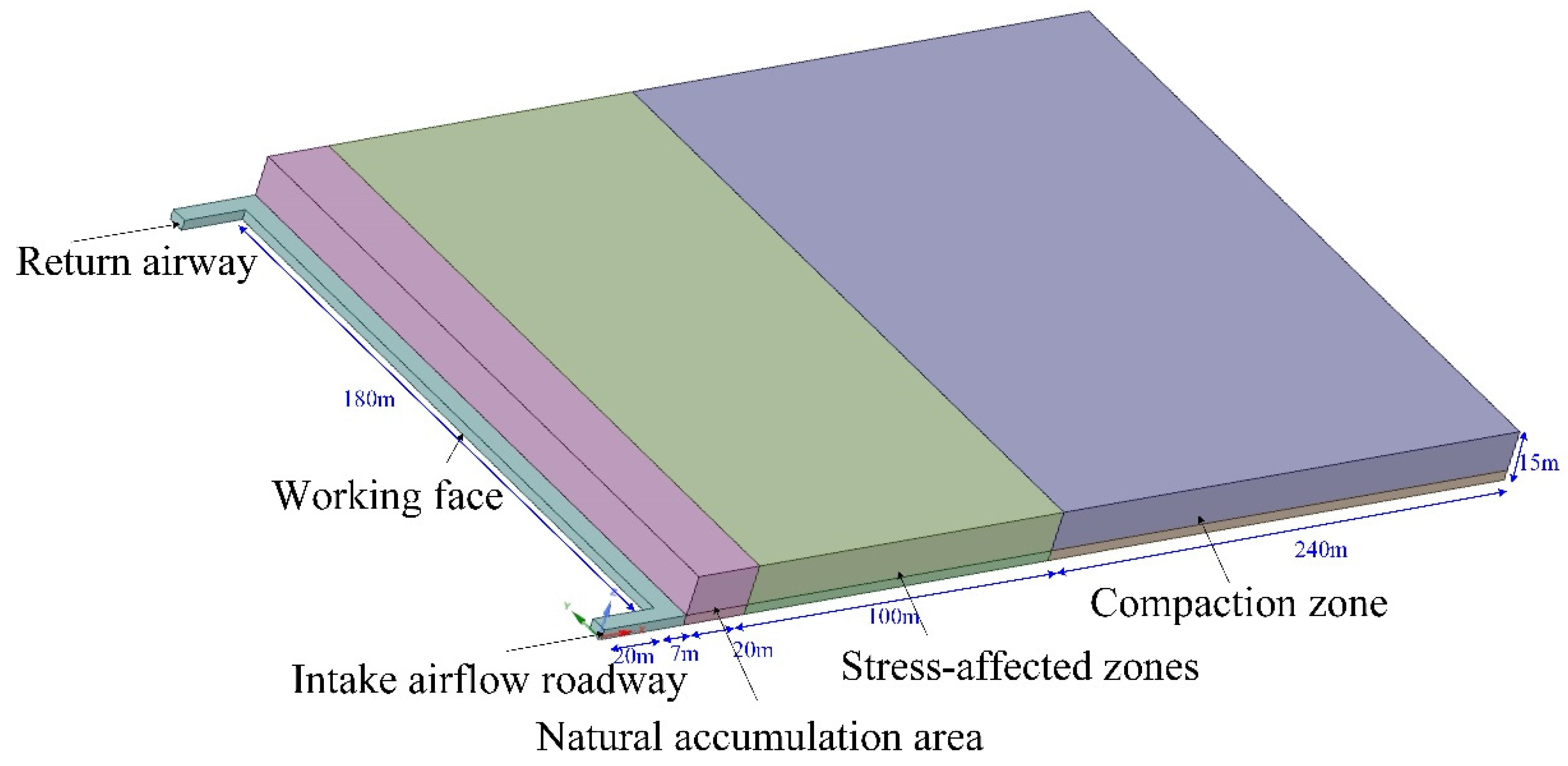
2. Overview of the Working Face

The working face, which adopted the “U”-shaped ventilation, is located in the No. 1 mining area of 8 # coal seam. The strike length is 1100 m, the incline length is 180 m, and the mean coal thickness is 1.08 m. The coal is mined using one-pass comprehensive mechanized coal mining and roof caving method. In order to prevent the methane from accumulation in the goaf and the upper corner, a drainage roadway is built at 20 m from the air return crossheading, and the large diameter boreholes are drilled in the coal pillar between the return airway and the drainage roadway. The layout of the working face is shown in Figure 1.

3. Numerical Computing Model

3.1. Numerical Computing Model for Methane Flow

Since the working face and the goaf have complex distribution, it is difficult to model according to the actual size [27,28,29]. Therefore, the impact of the equipment on the working face was not considered in the modeling, and the model size was simplified as follows: the working face was 180 m in width, the mining spacing was 7 m along the strike direction, the intake airflow roadway was 5 m in width and 3 m in height, the intake airflow roadway was 20 m along the strike direction, and the air volume of the intake airflow roadway was 1800 m3/min. The goaf was divided into three areas based on the compaction degree of the goaf strata: the natural accumulation area, the stress impact area, and the compaction area [18]. In the simulation, the range of the natural accumulation area, the stress impact area, and the compaction area was 0–20 m, 20–120 m, and 120–270 m, respectively. ICEM CFD was used for the modeling. The model was divided using an unstructured grid (Figure 2) and simulated on Fluent.
To simplify the calculation, the leakage of methane in three areas was regarded as continuous and uniform. Given that each area in the goaf has different compaction degree, the methane leakage source of each area can be determined based on the porosity:
Q i = Q s n i V i / ( n i V i )
where: Qs is the methane mass source term; ni is the porosity of each area in the goaf; Vi is the volume of each mass source.
According to the actual parameters of the working face, the parameters of each area in the goaf are shown in Table 1.

3.2. Simulation Scheme

To analyze the effect of the distribution of large-diameter boreholes and drainage parameters on the methane concentration in the goaf and the upper corner in a quantitative way, and to obtain the optimal borehole spacing and methane drainage parameters, this paper mainly studied the correlation between the three groups of influencing factors and the movement law of methane in the upper corner: (1) With or without large-diameter boreholes; (2) Large-diameter borehole spacing; (3) The distance between the first borehole and the upper corner.

4. Results and Analysis

4.1. With or without Large-Diameter Boreholes

In order to study the effect of large-diameter boreholes on the methane flow in the goaf, this paper simulated the distribution of methane concentration in the goaf and the working face with or without large-diameter boreholes. In the simulation, the large-diameter borehole spacing was 30 m, the first borehole was 15 m down the working face, and the methane drainage volume was 130 m3/min. The distribution of methane concentration was obtained through simulation (Figure 3).
As can be seen from Figure 3, the large-diameter boreholes have a great effect on the methane concentration in the upper corner. Figure 3a shows that under “U”-shaped ventilation, if no drainage methods are adopted, it can easily cause excessive methane concentration in the upper corner, which will lead to accidents. Figure 3b shows that when the methane drainage flow rate is 130 m3/min, the methane concentration in both the upper corner and the goaf is significantly reduced, and the methane concentration is reducing in the upper corner, the return airway, and somewhere near the third borehole. The simulation results show that the large-diameter boreholes in the goaf have a good effect on keeping the methane concentration of the working face and the goaf at a certain level and preventing the methane from outburst in the upper corner.

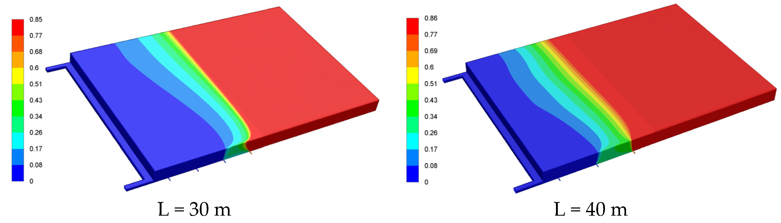
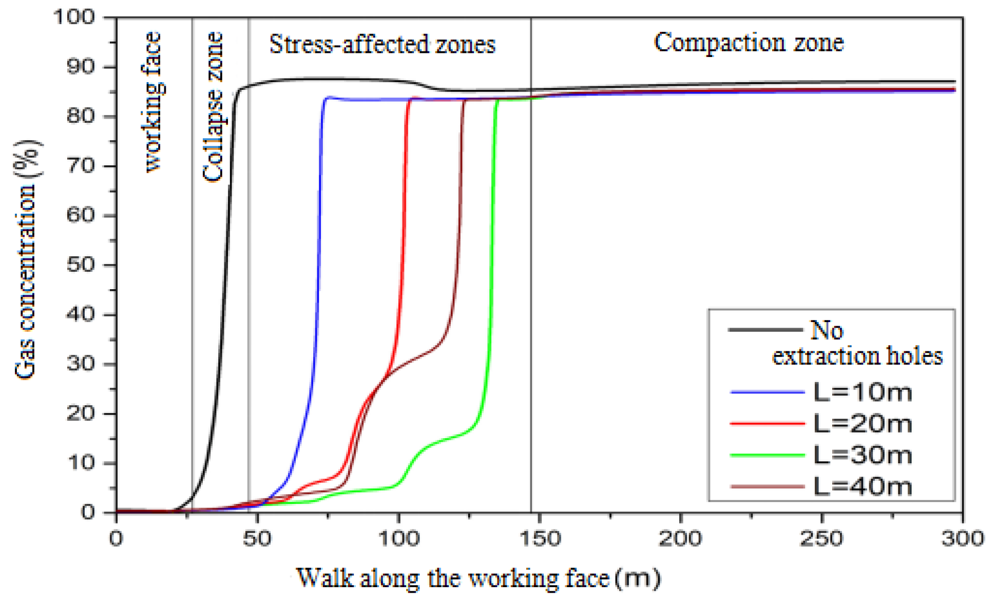
4.2. Large-Diameter Borehole Spacing

In order to study the effect of the large-diameter borehole spacing on the methane drainage effect, four large-diameter boreholes with a spacing L of 10 m, 20 m, 30 m, and 40 m were made, with the first borehole being 15 m down the upper corner and the drainage amount of each borehole being 130 m3/min. The distribution of methane concentration under different large-diameter borehole spacing is obtained through simulation (Figure 4). The methane concentration along the center line of the return airway is monitored (Figure 5), the monitoring origin of which is the entrance of the return airway.
From Figure 4, we can see that areas with high methane concentration gradually move to the working face as the borehole spacing has decreased. This shows that with the same number of boreholes, increasing the borehole spacing appropriately can improve the methane drainage effect in the goaf. Further observation shows that when the borehole spacing is 10 m, the methane concentration in the goaf rises sharply between the second and the third boreholes; when the borehole spacing is 20 m, the methane concentration in the goaf rise sharply between the third and the fourth boreholes; when the borehole spacing is 30 m, the methane concentration in the goaf rises sharply after crossing the third borehole; when the borehole spacing is 40 m, it is difficult for the air flow of the intake airflow roadway to reach the last borehole located in the compaction area, so the last borehole has little effect of draining methane. This shows that with the same number of boreholes, the smaller the borehole spacing, and the deeper the boreholes. The drainage, therefore, has limited effect, resulting in higher methane concentration. The larger the borehole spacing, the wider the distribution of the boreholes, so the borehole goes deep down the goaf and is far away from the working face, which has little effect on lowering the methane concentration. Therefore, the borehole spacing can be neither too large nor too small. According to the numerical computing results, the optimal borehole spacing under the parameters of this study is 30 m.
Figure 5 shows that when the borehole spacing is 10 m, the methane concentration in the direction of the measuring line rises rapidly at 75 m away from the origin; when the borehole spacing is 20 m, the methane concentration rises rapidly at about 100 m away from the origin; when the spacing is 30 m and 40 m, the methane concentration rises rapidly at about 125 m away from the origin; when the borehole spacing is 30 m, the methane concentration in the goaf is significantly lower than that when the spacing is 10 m, 20 m, and 40 m. This shows that the drainage achieves the best effect at the spacing of 30 m.

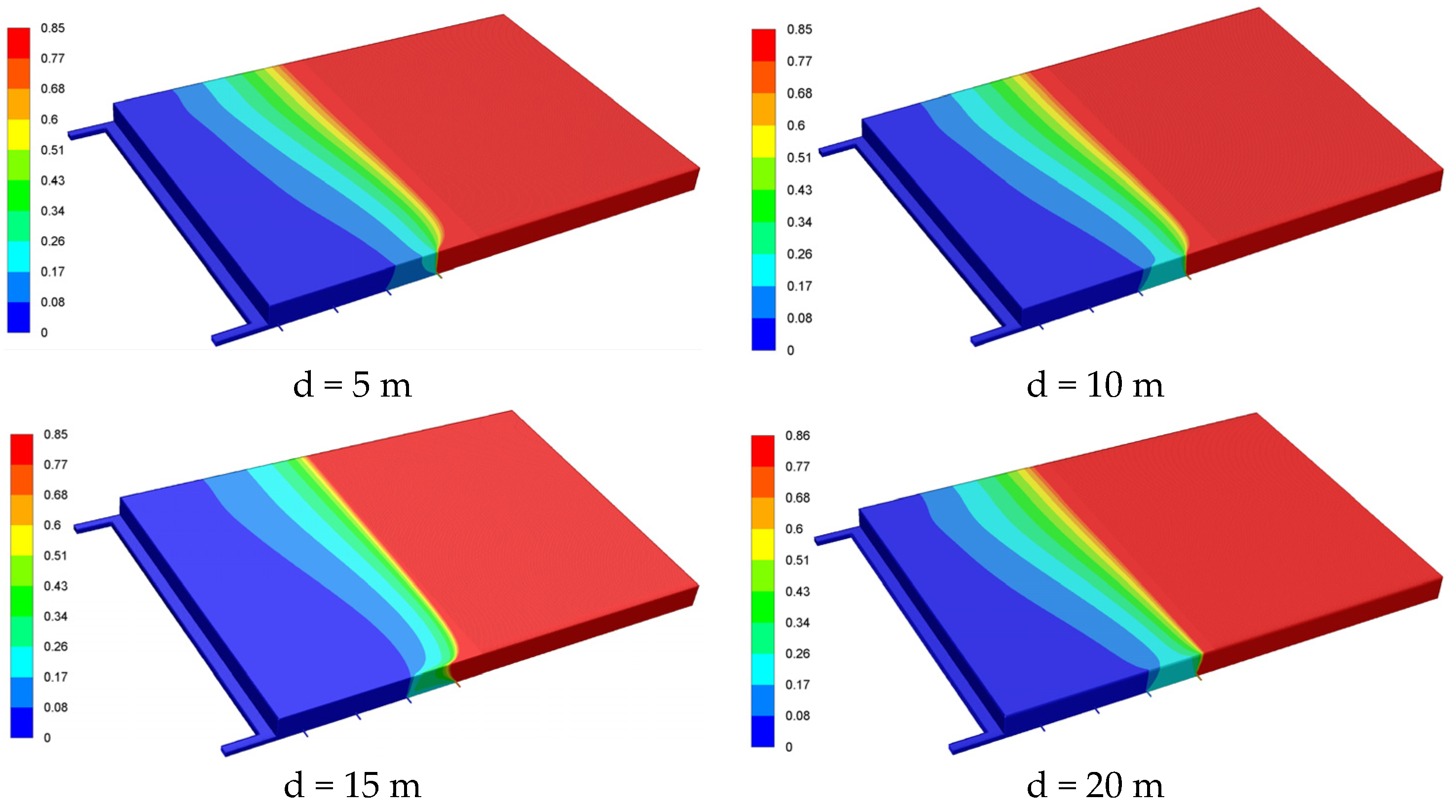
4.3. Distance between the Borehole and the Upper Corner

To study how the distance between the first large-diameter borehole and the upper corner affects the drainage effect, four large-diameter boreholes with a spacing of 30 m and a drainage amount of 130 m3/min were made, and the distance between the first borehole and the upper corner was kept at 5 m, 10 m, 15 m, and 20 m.
As can be seen from Figure 6, when the distance between the first borehole and the upper corner is d = 10 m or d = 20 m, the methane concentration between the third and the fourth boreholes is significantly higher than the condition when the distance is d = 5 m or d = 15 m. As the distance between the borehole and the upper corner increases, the area with low methane concentration is expanding. This shows that increasing the distance between the borehole and the upper corner appropriately helps reduce the methane concentration in the goaf. However, the methane concentration between the third and the fourth boreholes when the distance is d = 20 m is significantly higher than in the other conditions. From the cloud map of the methane concentration in the goaf, we can obtain the optimal distance between the first borehole and the upper corner, which is 15 m.
As can be seen from Figure 7, as the distance between the first borehole and the working face increases, the area with a sharp rise of methane concentration gradually shifts to the compaction area, but the advancing distance does not change significantly. According to the methane concentration on the measuring line and at 75 m away from the origin, the methane drainage effect at different distances between the borehole and the upper corner is almost the same, indicating that changing the distance between the borehole and the upper corner has little influence on the methane concentration in this area. At 100–125 m away from the origin, the drainage effect at d = 15 m and d = 20 m is better than that at d = 5 m and d = 10 m. However, in actual production, the farther the drainage entrance of the goaf is from the working face, the bigger the air leakage radius. Thus, it is easy to result in spontaneous combustion of residual coal in mines with such risks. For this reason, the drainage depth of the goaf with spontaneous combustion risks usually does not exceed 40 m. According to the simulation results, the distance between the borehole and the upper corner has little effect on the regional drainage when the first borehole is 75 m away from the origin (return airway entrance), which equals to 48 m from the upper corner. To ensure safe production, in most mines the draining begins when the distance between the borehole and the upper corner is 5 m, and the drainage achieves the best effect when the distance between the borehole and the upper corner is 15 m.

5. Field Test

Scheme Design

As shown in Figure 1, the boreholes with a diameter of 550 mm are drilled in the working face using ZDJ10000L crawler mine drilling machine to reduce the methane concentration in the upper corner. The borehole is 1.5 m deep down the floor, with a dip angle of 5° and borehole spacing of 30 m. In order to prevent the deformation of the borehole, the retaining pipe with a diameter of 426 mm is installed after the boreholes are drilled. The valve is set for each borehole and opened for networking drainage when the borehole is drilled 5 m deep down into the goaf. The blending volume of the single-borehole drainage is about 130 m3/min. When it is time for backstopping and as the first borehole goes deep down into the goaf, work begins on drilling the second one. When the second borehole is drilled 10 m deep into the goaf, the drilling of the first one stops. Such operation is applied to the rest of the boreholes. When the working face advances 100 m, the drilling of the third borehole suspends. The methane concentration in three boreholes and the upper corner is collected and the variation is shown in Figure 8 and Figure 9.
As can be seen from Figure 8, with the advancement of the working face, the borehole gradually goes deep down into the goaf, and the methane concentration in three boreholes increases as the distance between the borehole and the upper corner increases. When the distance between the borehole and the upper corner is about 25 m, the methane concentration in three boreholes increases rapidly. This shows that the borehole has penetrated into the stress impact area, whose medium porosity is smaller than that in the natural accumulation area and is close to the boundary range of the air leakage flow field in the goaf. When the distance between the borehole and the upper corner exceeds 35 m, the methane concentration in three boreholes remains basically stable. Among them, the methane concentration in the first and the second boreholes decreases slightly. This is because the third borehole near the working face begins to work out, resulting in some methane diversion in the goaf.
As can be seen from Figure 9, the methane concentration in the upper corner fluctuates between 0.32% and 0.51%, which is a result of extraction drilling replacement. As the borehole gradually penetrates into the goaf, the ability to control the methane concentration in the upper corner is gradually undermined. When the borehole is drilled about 25 m deep into the goaf, the methane concentration in the upper corner rises rapidly with the maximum reaching 0.51%. When the borehole is drilled 35 m deep into the goaf and the next borehole begins to work out, the methane concentration in the upper corner drops rapidly, and the overall concentration remains within a reasonable range. The influence of negative pressure in large-diameter drilling leads to the change of gas concentration in the upper corner. Drilling large-diameter boreholes in the adjacent drainage roadway can effectively control methane leakage in the upper corner, thus ensuring the safe production of the mine.

6. Conclusions

(1)
A reasonable spacing between large-diameter boreholes can effectively change the flow field of the goaf, and the low-pressure area formed at the borehole can manage the methane leakage in the air leakage flow field. Based on the actual geological conditions, physical scale, gas distribution, and other real parameters of the mine, the simulation results show that the optimal spacing of large-diameter boreholes in the goaf is 30 m, and when the boreholes are 15m away from the upper corner, the extraction effect is the best.
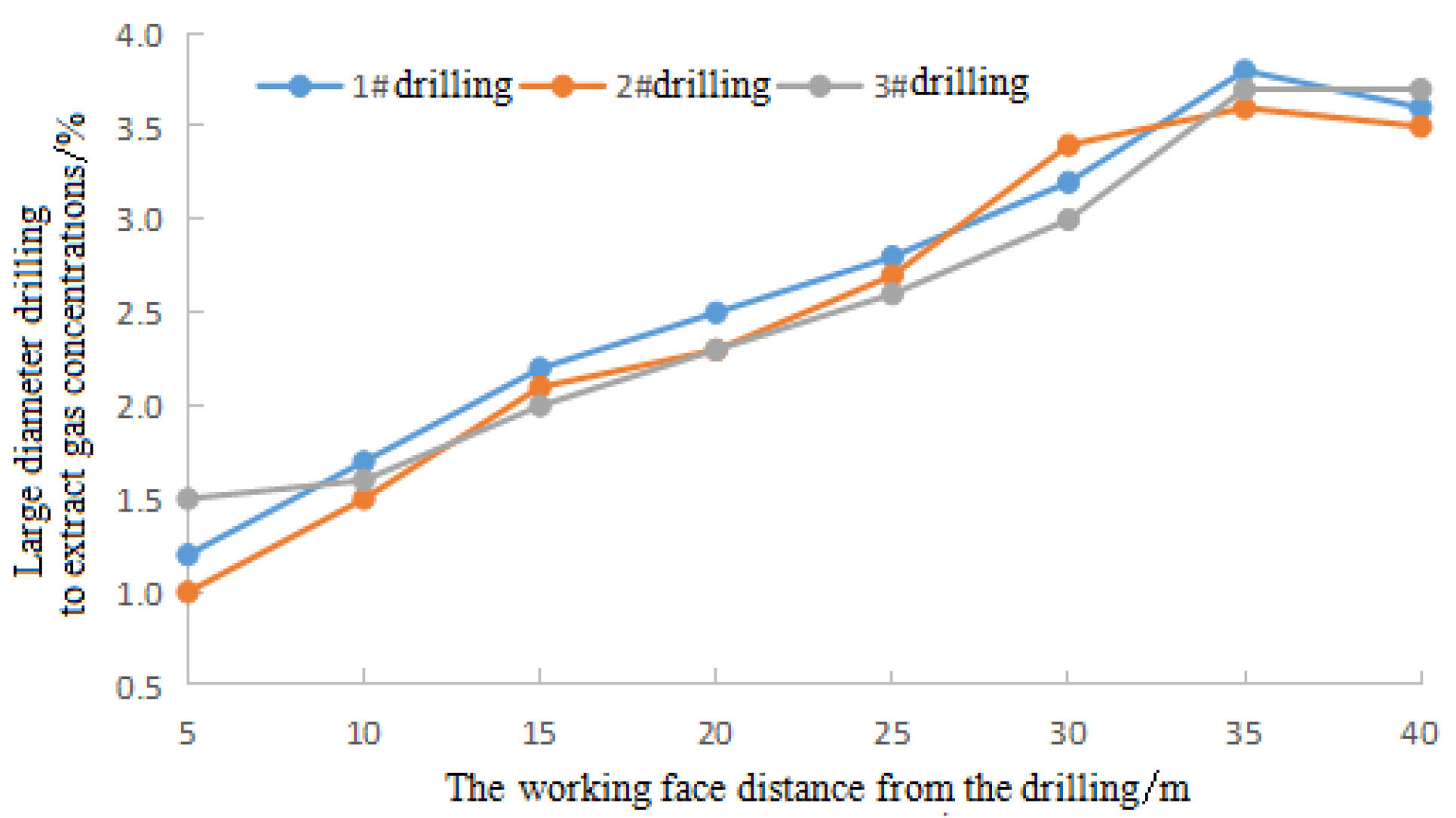
(2)
The field test shows that when the large-diameter borehole penetrates about 25 m deep into the goaf to reach stress impact area, the methane concentration of the boreholes increases rapidly with the decrease of the porosity (less air leakage), with the maximum being 3.7%. As a result of the drainage superposition effect, when the borehole is drilled 35 m deep into the goaf, the methane concentration of the boreholes slightly decreases.
(3)
The methane concentration in the upper corner increases as the distance between the borehole and the upper corner increases. As a result of the drainage superposition effect, the methane concentration in the upper corner changes from 0.32% to 0.51% in a cyclic way.

Funding

This research received no external funding.

Data Availability Statement

The data used to support the findings of this study are available from the corresponding author upon request.

Conflicts of Interest

The authors declare no conflict of interest.

References

  1. Si, L.L.; Xi, Y.J.; Wei, J.P.; Li, B.; Wang, H.; Yao, B.; Liu, Y. Dissolution characteristics of gas in mine water and its application on gas pressure measurement of water-intrusion coal seam. Fuel 2022, 313, 123004. [Google Scholar] [CrossRef]
  2. Özgen Karacan, C.; Martín-Fernández, J.A.; Ruppert, L.F.; Olea, R.A. Insights on the characteristics and sources of gas from an underground coal mine using compositional data analysis. Int. J. Coal Geol. 2021, 241, 103767. [Google Scholar] [CrossRef]
  3. Liu, P.; Fan, J.Y.; Jiang, D.Y.; Li, J. Evaluation of underground coal gas drainage performance: Mine site measurements and parametric sensitivity analysis. Process Saf. Environ. Prot. 2021, 148, 711–723. [Google Scholar] [CrossRef]
  4. Chen, X.J.; Zhao, S.; Li, L.Y.; Li, X.; Kang, N. Effect of ambient pressure on gas adsorption characteristics of residual coal in abandoned underground coal mines. J. Nat. Gas Sci. Eng. 2021, 90, 103900. [Google Scholar] [CrossRef]
  5. Song, R.; Liu, J.J.; Yang, C.; Sun, S. Study on the multiphase heat and mass transfer mechanism in the dissociation of methane hydrate in reconstructed real-shape porous sediments. Energy 2022, 254, 124421. [Google Scholar] [CrossRef]
  6. Gao, K.; Li, S.N.; Liu, Y.J.; Jia, J.; Wang, X. Effect of flexible obstacles on gas explosion characteristic in underground coal mine. Process Saf. Environ. Prot. 2021, 149, 362–369. [Google Scholar] [CrossRef]
  7. Yu, D.; Ma, Z.; Wang, R. Efficient smart grid load balancing via fog and cloud computing. Math. Probl. Eng. 2022, 2022, 3151249. [Google Scholar] [CrossRef]
  8. Zhu, Z.; Wu, Y.; Liang, Z. Mining-Induced stress and ground pressure behavior characteristics in mining a thick coal seam with hard roofs. Front. Earth Sci. 2022, 10, 843191. [Google Scholar] [CrossRef]
  9. Zhang, L.; Huang, M.; Li, M.; Lu, S.; Yuan, X.; Li, J. Experimental study on evolution of fracture network and permeability characteristics of bituminous coal under repeated mining effect. Nat. Resour. Res. 2021, 31, 463–486. [Google Scholar] [CrossRef]
  10. Liu, Y.; Zhang, Z.; Liu, X.; Wang, L.; Xia, X. Ore image classification based on small deep learning model: Evaluation and optimization of model depth, model structure and data size. Miner. Eng. 2021, 172, 107020. [Google Scholar] [CrossRef]
  11. Zhang, G.; Zhang, Z.; Sun, M.; Yu, Y.; Wang, J.; Cai, S. The influence of the temperature on the dynamic behaviors of magnetorheological gel. Adv. Eng. Mater. 2022, 2101680. [Google Scholar] [CrossRef]
  12. Dong, J.; Deng, R.; Quanying, Z.; Cai, J.; Ding, Y.; Li, M. Research on recognition of gas saturation in sandstone reservoir based on capture mode. Appl. Radiat. Isot. 2021, 178, 109939. [Google Scholar] [CrossRef]
  13. Lei, B.W.; He, B.B.; Zhao, Z.D.; Xu, G.; Wu, B. A method for identifying the fire status through ventilation systems using tracer gas for improved rescue effectiveness in roadway drivage of coal mines. Process Saf. Environ. Prot. 2021, 151, 151–157. [Google Scholar] [CrossRef]
  14. Wang, K.; Zhang, X.; Wang, L.; Li, L.; Zhang, M.; Zhou, A. Experimental study on propagation law of shock wave and airflow induced by coal and gas outburst in mine ventilation network. Process Saf. Environ. Prot. 2021, 151, 299–310. [Google Scholar] [CrossRef]
  15. Song, R.; Sun, S.Y.; Liu, J.J.; Feng, X. Numerical modeling on hydrate formation and evaluating the influencing factors of its heterogeneity in core-scale sandy sediment. J. Nat. Gas Sci. Eng. 2021, 90, 103945. [Google Scholar] [CrossRef]
  16. Yu, D.; Wu, J.; Wang, W.; Gu, B. Optimal performance of hybrid energy system in the presence of electrical and heat storage systems under uncertainties using stochastic p-robust optimization technique. Sustain. Cities Soc. 2022, 83, 103935. [Google Scholar] [CrossRef]
  17. Liu, Y.; Zhang, Z.; Liu, X.; Wang, L.; Xia, X. Efficient image segmentation based on deep learning for mineral image classification. Adv. Powder Technol. 2021, 32, 3885–3903. [Google Scholar] [CrossRef]
  18. Zhang, L.; Huang, M.; Xue, J.; Li, M.; Li, J. Repetitive mining stress and pore pressure effects on permeability and pore pressure sensitivity of bituminous coal. Nat. Resour. Res. 2021, 30, 4457–4476. [Google Scholar] [CrossRef]
  19. Fan, C.; Li, H.; Qin, Q.; He, S.; Zhong, C. Geological conditions and exploration potential of shale gas reservoir in Wufeng and Longmaxi Formation of southeastern Sichuan Basin, China. J. Pet. Sci. Eng. 2020, 191, 107138. [Google Scholar] [CrossRef]
  20. Hu, S.; Wu, H.; Liang, X.; Xiao, C.; Zhao, Q.; Cao, Y.; Han, X. A preliminary study on the eco-environmental geological issue of in-situ oil shale mining by a physical model. Chemosphere 2020, 287, 131987. [Google Scholar] [CrossRef]
  21. Gao, H.; Yang, H.W. Super large diameter borehole gob gas extraction technology. Coal Sci. Technol. 2019, 47, 77–81. [Google Scholar]
  22. Jia, J.Z.; Guo, J. Application of large diameter extraction drilling in goaf gas drainage. J. Liaoning Technol. Univ. Nat. Sci. 2020, 39, 1–5. [Google Scholar]
  23. Shao, G.A.; Zou, Y.M. Prevention technology of residual coal spontaneous combustion in goaf un-der the condition of large diameter borehole extraction. Saf. Coal Mines 2020, 51, 74–77. [Google Scholar]
  24. Yang, Q.Y.; Luo, H.G.; Shi, B.M.; Zhang, L.L.; Zhang, H.Z. Numerical study on drainage parameters optimization of buried pipe in goaf based on COMSOL. J. Saf. Sci. Technol. 2019, 15, 90–95. [Google Scholar]
  25. Shi, G.Q.; Wang, G.Q.; Ding, P.X.; Wang, Y.M. Model and simulation analysis of fire development and gas flowing influenced by fire zone sealing in coal mine. Process Saf. Environ. Prot. 2021, 149, 631–642. [Google Scholar] [CrossRef]
  26. Zhang, L.; Li, J.; Xue, J.; Zhang, C.; Fang, X. Experimental studies on the changing characteristics of the gas flow capacity on bituminous coal in CO2-ECBM and N2-ECBM. Fuel 2021, 291, 120115. [Google Scholar] [CrossRef]
  27. Shen, X.; Hong, Y.; Zhang, K.; Hao, Z. Refining a distributed linear reservoir routing method to improve performance of the crest model. J. Hydrol. Eng. 2017, 22, 4016061. [Google Scholar] [CrossRef]
  28. Li, J.B.; Cheng, F.; Lin, G.; Wu, C.L. Improved hybrid method for the generation of ground motions compatible with the multi-damping design spectra. J. Earthq. Eng. 2022, 1–27. [Google Scholar] [CrossRef]
  29. Zhang, G.; Chen, J.; Zhang, Z.; Sun, M.; Yu, Y.; Wang, J.; Cai, S. Analysis of magnetorheological clutch with double cup-shaped gap excited by Halbach array based on finite element method and experiment. Smart Mater. Struct. 2022, 31, 075008. [Google Scholar] [CrossRef]
Figure 1. Layout of the working face.
Processes 10 01669 g001
Figure 2. Numerical computing model for methane flow.
Processes 10 01669 g002
Figure 3. The distribution of methane concentration. (a) Without large-diameter boreholes. (b) With large-diameter boreholes.
Processes 10 01669 g003
Figure 4. The distribution of methane concentration under different borehole spacing.
Processes 10 01669 g004aProcesses 10 01669 g004b
Figure 5. Methane concentration distribution along the center line of the return airway at different borehole spacing.
Processes 10 01669 g005
Figure 6. Distribution of methane concentration under different distance between the first borehole and the upper corner.
Processes 10 01669 g006
Figure 7. Distribution of methane concentration along the center line of the return airway at different distances between the borehole and the upper corner.
Processes 10 01669 g007
Figure 8. Variation of the methane concentration in three boreholes.
Processes 10 01669 g008
Figure 9. Variation of the methane concentration in the upper corner.
Processes 10 01669 g009
Table 1. Parameters of each area.
AreaWorking FaceNatural Accumulation AreaStress Impact AreaCompaction Area
Porosity -0.36%0.24%0.09%
Source item 2.78 × 10⁻⁵ kg/m3·s6.66 × 10−75 kg/m3·s5.78 × 10−75 kg/m3·s4.88 × 10−75 kg/m3·s
Publisher’s Note: MDPI stays neutral with regard to jurisdictional claims in published maps and institutional affiliations.

