Article

Study of Prevention and Control Technology for Roadway Excavation under the Soft and Extra-Thick Coal Roof in Luling Coal Mine

1
State Key Laboratory of Mining Response and Disaster Prevention and Control in Deep Coal Mines, Anhui University of Science and Technology, Huainan 232000, China
2
Key Laboratory of Ministry of Education for Efficient Coal Working Sponsored Jointly by Anhui Province and Ministry of Education, Anhui University of Science and Technology, Huainan 232000, China
3
School of Mining Engineering, Anhui University of Science and Technology, Huainan 232000, China
4
Heilongjiang Ground Pressure & Gas Control in Deep Mining Key Lad, Heilongjiang University of Science & Technology, Harbin 150022, China
5
Post-Doctoral Research Station, Huaibei Mining Corporation Limited, Huaibei 235000, China
*
Author to whom correspondence should be addressed.
Processes 2022, 10(9), 1835; https://doi.org/10.3390/pr10091835
Submission received: 8 June 2022 / Revised: 22 August 2022 / Accepted: 8 September 2022 / Published: 12 September 2022

Abstract

:
In view of the problems associated with the poor stability of coal walls, coal slide and leakage of top-coal at the tunnel excavation working face under a soft and extra-thick coal roof, the surrounding rock at the tunnel excavation working face must be strengthened. The theoretical analysis of rock pressure, numerical simulation and other methods were comprehensively used to study the coal-wall-slicing mechanism. Given the characteristics of a soft and extra-thick coal roof, the combined supporting technology of “coal wall water injection + metal roof frame” is proposed. The findings show that in the process of roadway excavation, the coal–rock junctions of the wall and the middle part of the roof are weak areas that are prone to spalling and therefore need to be strengthened. Laboratory tests determined the moisture content of the coal body during tunneling to provide data for the parameter design of coal wall water injection. Safe and efficient excavation of the roadway was ensured by injecting water into the coal wall in combination with a metal roof protection skeleton. The application of this technology not only effectively prevents rib spalling but improves control of the deformation of the surrounding rock. During 40 days of field observation, the maximum deformation of the roof was 24.8 mm, and the distance between the two roadway walls was 21.5 mm. The deformation of the roadway was controlled within a safety zone. The application of this technology reduced the repair rate of the roadway and improved the efficiency of the roadway excavation. It brought significant economic benefits and provides an important reference for similar mines.

1. Introduction

Coal production is important for both the national economy and people’s livelihoods, and coal mine safety is a prerequisite for coal production. In the process of roadway excavation under soft and extra-thick coal seams, the roof and floor of the coal body are prone to wall and roof collapse [1,2,3]. The presence of coal wall slices increases the difficulty of supporting the walls and roof. If these are not well controlled, they will cause the fall of roof coal and “roof leakage” [4,5]. The difficulties are not limited to the heading face but can also cause safety incidents, which result in huge losses to safe and efficient coal mining and significantly impede improvement in production efficiency [6,7,8]. Many scholars and experts have investigated the mechanism and laws relating to coal wall caving and advanced scientific research in this area [9,10,11]. Studies have observed the mechanism and regularity of rib spalling of roadways in extremely soft and thick coal seams [12,13,14,15]. The research results have revealed the local rib spalling mechanism of the surrounding rock but do not cover the influence of the coal seam dip angle on the rib spalling of the surrounding rock [16]. The literature has studied soft and extra-thick coal seams and concluded that in the process of roadway excavation, roof fracture can easily occur as the bearing capacity of the coal and rock mass is weakened, resulting in collapse of the surrounding rock and roof fall [17,18]. Prevention of soft coal wall spalling can be addressed in the following three ways. Firstly, the tunneling process can be optimized. Secondly, the speed of tunneling can be accelerated. Finally, advance support can be provided in a timely way. The above measures are not effective in isolation, and they must be coordinated with each other and with the actual project in order to achieve better construction results. Because of the poor self-supporting capacity of soft coal, it is particularly important to use physical and chemical methods to improve the properties of the coal itself to prevent coal wall clumps. Coal wall water injection is an effective method to change the properties of coal. The literature shows that coal seam water injection can increase the cohesion and shear resistance of coal bodies and reduce the development of plastic zones in the coal–rock mass [19,20]. These studies conclude that water injection has positive effects on the stability of soft coal seams [21,22,23,24]. Building on previous studies, the research objectives of our study are the prevention and control of coal wall caving in the roadway under loose soft and thick coal seams in order to reduce the driving roadway repair rate and improve production efficiency.

2. Numerical Simulation Calculation

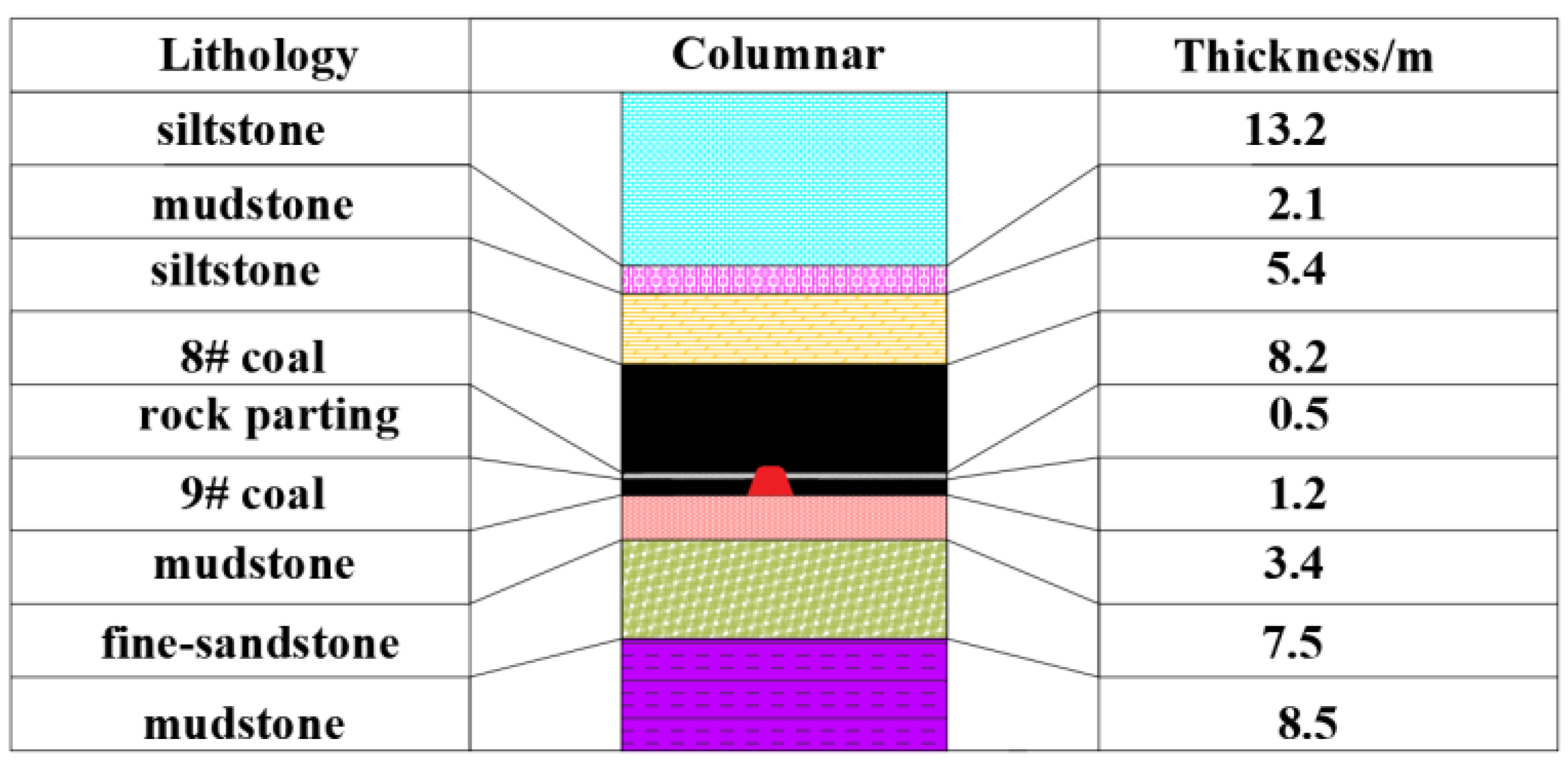
2.1. Engineering General Situation

It is known from geological survey borehole data that the Luling coal mine 3811 heading face of the 8# and 9# coal merges in most areas. There is a gangue between the 8# coal and 9# coal. The thickness of the 8# coal seam is 1.8–14.25 m, with an average thickness of 8.25 m. The thickness of the 9# coal seam is 0.2–3.3 m, with an average thickness of 1.51 m. The coal seam dip angle is 13–22°, with an average dip angle of 16°. The gangue thickness between the 8# coal and the 9# coal is approximately 1.4–4.27 m, and the average thickness is approximately 1.2 m. The position of 8# coal and 9# coal in the section with the roadway is shown in Figure 1.

2.2. Establishment of a Calculation Model

We used the engineering and geological data relating to the Luling coal mine heading face to study the development and evolution trends of stress, displacement, and plastic zones after roadway excavation. FLAC3D software (Minneapolis, Minnesota, MN, USA) was utilized to create models for the numerical calculations. According to the elastic–plastic theory, the influence range of roadway excavation was fully considered, and a range five times greater than the roadway radius was appropriately selected as the model boundary. In this model, the coordinate system was as follows: the X-axis was horizontal to the direction of the roadway excavation, the Y-axis was in line with the roadway excavation direction, and the Z-axis was vertical drift and upwards represented a positive value. The numerical simulation setting was l X = 50 m, l Y = 100 m, and l Z = 50 m. The upper part of the model was a free boundary, where other boundaries of the model were set as single constraint boundaries. The depth of the roadway was 600 m. Applied pressure on the upper boundary was σ Z = 14.25 MPa. The side pressure coefficient was λ = 1.2 . Firstly, the stress state of the original rock was simulated, and the displacement was reset to zero after the stress reached equilibrium, and then the roadway was excavated and calculated to achieve equilibrium. The cable structure was used to simulate the anchor rod and cable, and the beam structure element was used to simulate the support of the U-shaped shed. The calculations were carried out using the Mohr–Coulomb elastoplastic constitutive model in order to study the stress, displacement, and the development of the plastic zone at different positions in the process of roadway excavation. The location of the heading head was 0 m, 1.2 m, 2.4 m. Through numerical simulation, the stress environment of different positions in the process of excavation was understood, and the location prone to slip was clear to provide the theory instruction for the anti-slip site. We added geometry of the numerical simulation to make it easier to read. The revised part has been marked in red. In this numerical calculation, the initial geostatic stress was first balanced, and then the roadway was excavated. The simulated roadway was set as a trapezoidal roadway. The parameters of the model were calculated until a balance was achieved. The calculation model is shown in Figure 2.

2.3. Analysis of Numerical Results

In this paper, the stress field, horizontal displacement field, and the development plastic zone range of surrounding rock at different positions in relation to the excavation roadway were studied. The physical and mechanical parameters of the coal and rock were obtained from the collected borehole columnar data. The numerical calculation model of the trapezoidal roadway was established. The numerical calculation model has 9 strata. The physical and mechanical parameters of the coal and rock are shown in Table 1.

2.4. Analysis of Numerical Results

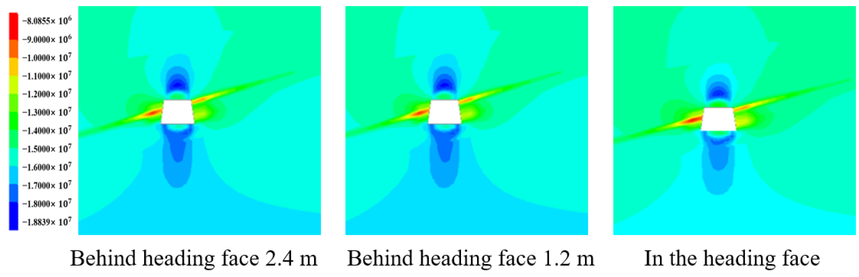
2.4.1. Analysis of the zz-Stress Field

The zz-stress contour in the different ranges of heading faces is shown in Figure 3. After roadway excavation, the stress was redistributed and released in the central area of the roadway roof and floor to form a pressure relief area. A stress concentration area formed in the two bottom corners of the roadway. Because to the 16° dip angle of the coal and rock stratum, the stress relief and concentration area were asymmetric. The vertical stress at a position 2.4 m away from the excavation head was significantly greater than that at the excavation head, and the maximum vertical stress was about 21.759 MPa. The stress concentration factor was calculated to reach 1.43. The stress concentration area was behind the excavation head, indicating that timely support was required after roadway excavation.

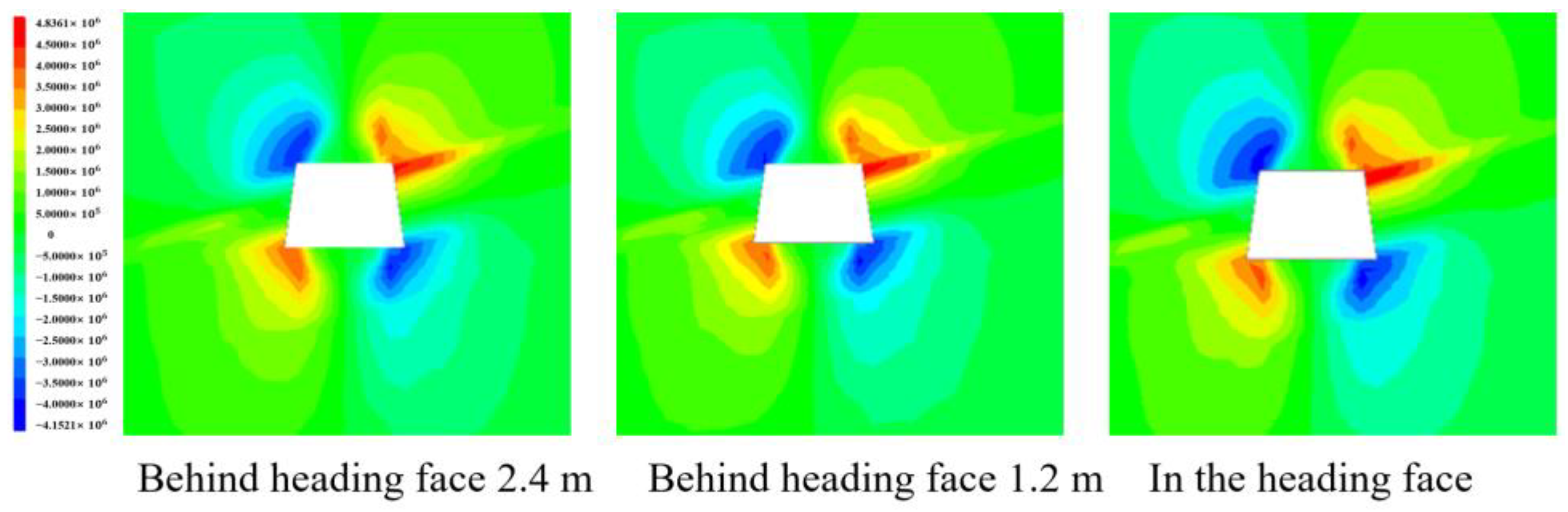
2.4.2. Analysis of the xx-Stress Field

The xx-stress contour in the different ranges of heading faces is shown Figure 4. After roadway excavation, the horizontal stress at different ranges from the excavation head showed the same trend, and the stress values were significantly different. After roadway excavation, a certain range of the shallow surrounding rock formed a pressure relief area, the vertical stress concentration appeared in the roadway roof and floor, and the stress reduction area appeared at the side of the roadway as a result of excavation and was asymmetric because of the coal seam inclination. The reason for this was that the upper part of the roadway had a thick coal roof that was of low intensity and large inclination, resulting in coal and rock with low strength and fracture joints caused by mining. The roof and slope became increasingly loose and broken during roadway excavation. The concentration of horizontal stress led to the failure of the coal and rock mass near the roadway once it exceeded the ultimate strength, resulting in spalling the roadway excavation process. At the same time, stress reduction appeared at the coal–rock interface, resulting in the obvious difference between vertical stress and horizontal stress at the coal–rock interface. The stress distribution difference caused destruction and spalling in the coal–rock interface area. Therefore, the coal–rock interface area needed to be strengthened in the excavation process of this area.

2.4.3. Analysis of the xz-Stress Field

The xz-stress contour in the different range of heading faces is shown in Figure 5. The shear stress is the interaction force of any internal section in the process of force and deformation of an object. In the process of roadway excavation, the distribution law of shear stress at different positions behind the excavation head is the same. The shear stress at the four corners of the roadway was “diagonally symmetrical”, which showed the distribution characteristics of a “double core” shape. Shear stress was the smallest in the direction almost perpendicular to the dip angle of the coal seam. The minimum shear stress area appeared around the roadway almost parallel with the coal seam, and the roof area was significantly larger than the floor area, indicating that the vertical stress had a significant impact on it after roadway excavation. The dip angle influenced the distribution of shear stress around the roadway, and the dip angle of the coal seam was an important factor that could not be ignored. Because the rock had better compression but weak tensile and shear properties, the shear stress concentration area caused the development of longitudinal fractures in the coal and rock mass, reducing the integrity of the slope area and the strength of coal and rock mass. The shear stress 2.4 m behind the excavation head was greater than at the excavation head. Once the driving position became the free face, the shear failure caused the coal to slide from the side, which explained why the side appeared in the driving face of the soft and extra-thick coal seam.

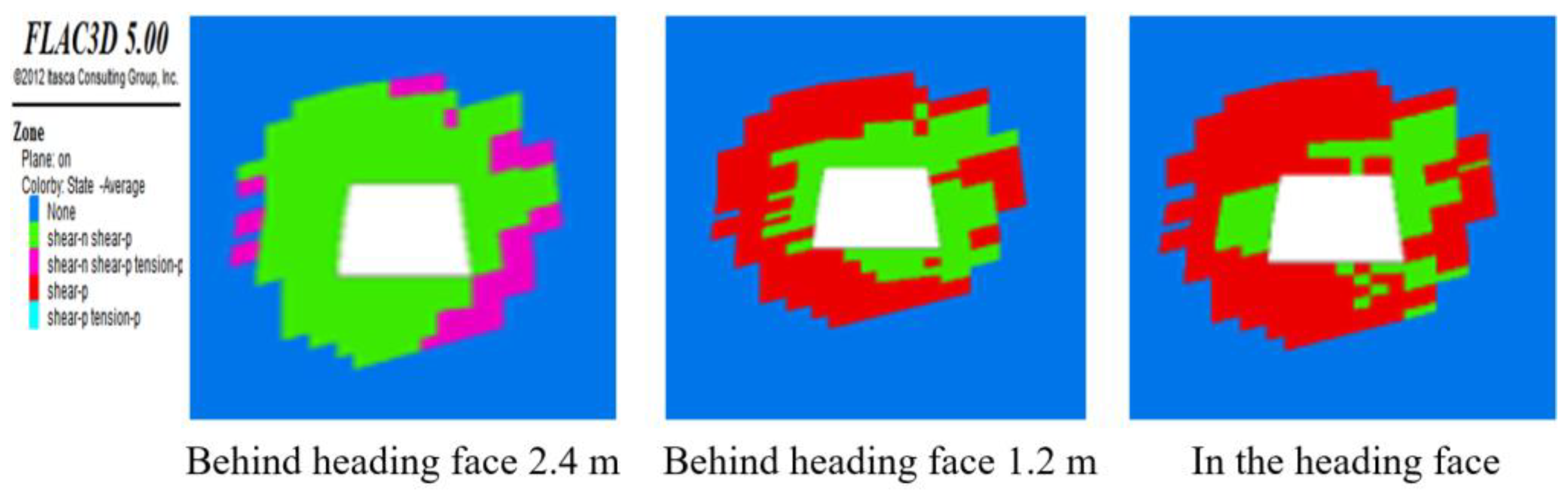
2.4.4. Development and Evolution of the Plastic Zone in the Rock Surrounding the Roadway

The plastic zone contour in the different range of heading faces is shown in Figure 6. At the position of roadway excavation, the failure mode in the near area of the roadway floor and roof was mainly a tensile failure. In the areas farther away from the roadway, the failures were in the form of past shear, present shear, and past tension. At a distance of 1.2 m behind the heading face, the area close to the roadway was mainly a shear failure, and the external area was a past shear failure. At 2.4 m behind the heading face, the two sides of the roadway along the dip direction of the coal seam showed shear failure, and a past shear failure appeared in a large area of the roof and floor. The main reason for this was that the original three-dimensional stress state was changed into a two-dimensional stress state due to the generation of the free face after the excavation of the roadway, This greatly reduced the strength and bearing capacity of the surrounding rock, which specifically showed that the coal and rock mass at the top and side was loose and broken, and the side was prone to spall.
Through the numerical calculations relating to roadway excavation in soft and extra-thick coal seams, it could be seen that the coal slope mainly occurred in places where the coal and rock connected with the roadway. The development range of stress concentration area and plastic zone could be better understood through numerical simulation. It could better guide the prevention of coal wall spline, which could increase the tunnelling rate, speed up the production schedule, and improve engineering quality.

3. Study of Coal Wall Water Injection to Prevent Splicing

3.1. Mechanism to Modify Coal Wall Water Injection

After the roadway was excavated, many cracks would be produced in the surrounding rock of the roadway due to unloading. After effective coal seam water injection, the seam became a three-phase aggregate composed of solid particles, pore water, and air. The research and experimental results showed that the mechanical properties of the coal were clearly changed; the elasticity and strength of the coal were reduced, whereas its plasticity was increased. Thus, the pressure distribution at the front of the roadway was changed. The high pressure was transferred to the deep coal seam, and the pressure concentration coefficient was reduced. According to the effective stress principle of soil mechanics, the stress produced by an external load on a three-phase medium was transmitted through the contact of solid particles, and the total external stress was borne by coal particles and pore fluid. When the coal seam reached the pore water pressure, the stress surface followed the relationship:
S = S 1 + S 2
In the formula, S is the area of the coal unit, the unit is m2; S 1 is the area of the particle contact point, the unit is m2; and S 2 is the area of pore water, the unit is m2.
Water is fluid, and it flows under the action of external force and gravity. Pore water pressure is different in terms of the internal particles of a coal and rock mass. The total stress, pore water pressure, and effective stress have the following relationship:
σ = Σ P S V S + P
In the formula, P is pore water pressure, the unit is MPa; σ is total stress, the unit is MPa; and P S V is the normal force acting on the contact point of solid particles, the unit is N. Therefore, the force on solid particles in a loose coal seam decreases after water injection and effectively relieves the stress on the coal wall, thereby enhancing the stability of the coal wall and reducing the occurrence of the sidewall.

3.2. Determination of Water Injection Parameters

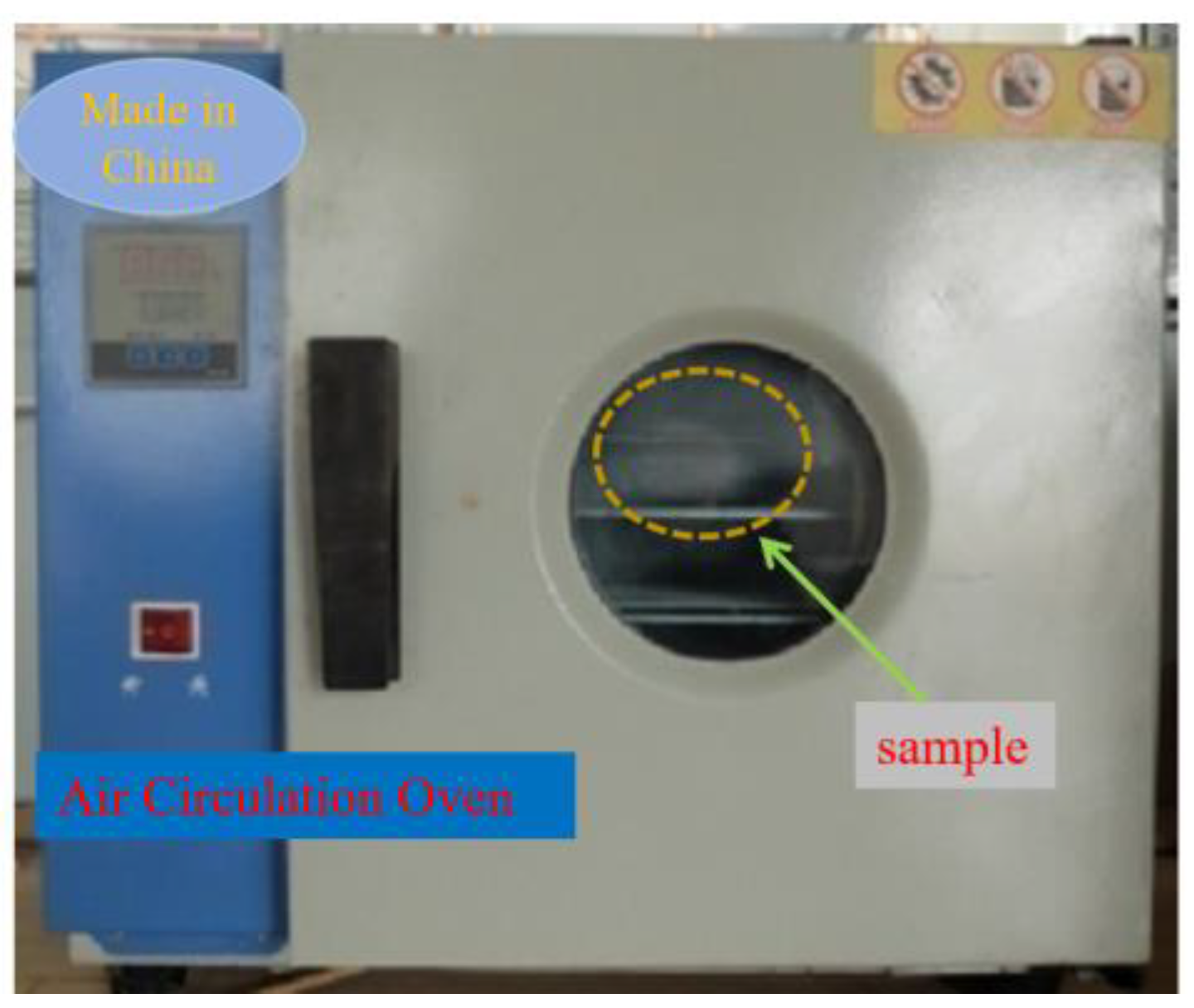
3.2.1. Determination of Moisture Content of Coal

We took raw coal samples from the coal seam of the excavation roadway and sealed them to ensure they were in pristine condition for moisture content testing at the laboratory. The original moisture content of the coal refers to the ratio of the moisture content of the coal in the natural state to the solid mass. The original moisture content of the coal was measured according to the determination method of physical and mechanical properties of coal and rock GB/T23561.6-2009, and the preparation of coal samples was in accordance with Geotechnical test method standard (GB/T50123-1999). Firstly, coal samples with a particle size not greater than 6 mm and a weight of 1 g, were into the drying oven. These were heated at 105~110 °C for 24 h and then weighed, and the moisture content was calculated according to the mass loss of the coal samples. Experimental equipment included: an electrothermal drying oven with an automatic temperature control device and blower, balance (precision 0.001 g), ring knife, and plastic wrap. The electric drying oven is shown in Figure 7.
The moisture content of the coal sample was calculated as follows:
ω = m 2 m 3 m 3 m 1 × 100
In the formula: m 1 is the weight of the volume bottle, the unit is g; m 2 is the weight of the volumetric flask and the original coal sample, the unit is g; and m 3 is the weight of the volumetric flask and coal sample after drying, the unit is g.
Photographs of the test weighing of the coal samples are shown in Figure 8. From the experiment, we established that the moisture content of the raw coal sample was 3.858%. Relevant literature [25,26] indicated that coal particles had better cohesion with a water content in the range of 4–5%, guaranteeing the high strength of a coal seam. Thus, water injection was required.

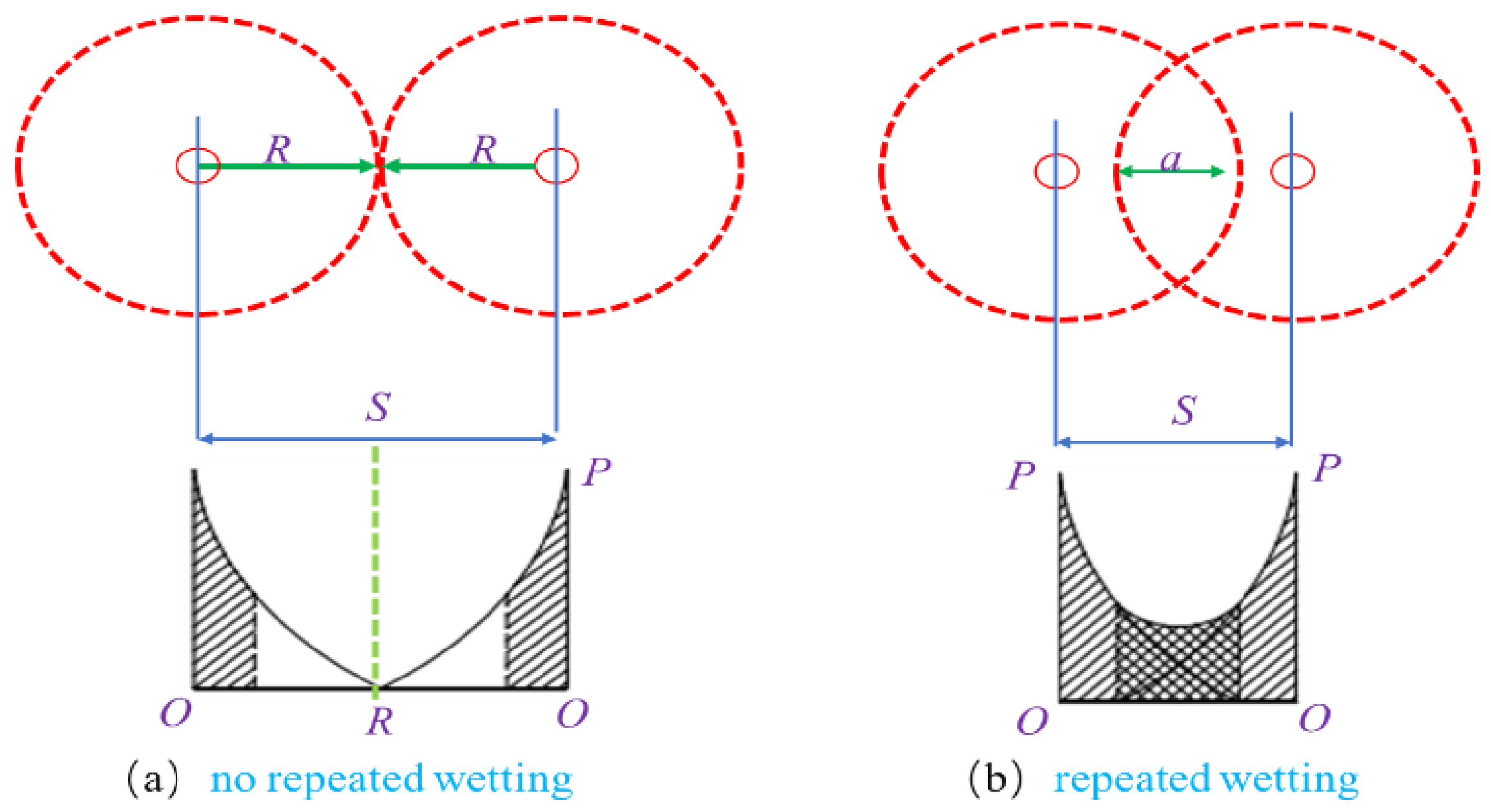
3.2.2. Water Injection Depth

According to previous research, it could be seen that cracks develop near the destruction zone of a coal seam. Therefore, water injection in the destruction and fracture development zone could not only ensure the spread of water molecules because of the fracture development, but also make full use of the water to wet the coal seam. To ensure the formation of a certain strength and thickness of the bonding layer within the scope of the broken zone after water injection in the working face, it was necessary to ensure that the water injection did not affect the normal tunneling of the heading face, for example by making sure that the depth of the water injection hole was greater than the width of the broken zone. The amount of drilling in the working face and the labor intensity of the workers should also be considered. From the analysis above, the width of the roadway broken zone was 3.58 m, which determined that the depth of the water injection hole was 4–5 m.

3.2.3. Water Injection Hole Layout

The numerical calculation showed that the stress concentration area of the rock surrounding the roadway and the foundation crushing area was in the coal–rock junction area. The position where the coal wall was prone to spall was 1.2 m away from the roadway roof. The wetting radius needed to be taken into consideration. The height of the optimized borehole from the heading face roof was 1.32 m, and the spacing of water injection holes should be determined according to the wetting radius of water. There were two wetting modes: no repetitive wetting and repeated wetting, as shown in Figure 9.
When the coal seam was not wetted repeatedly (Figure 9a), the water injection pressure gradually decreased away from the water injection hole. When the wetting radius of two water injection holes were tangent, the water injection holes were:
S = 2 R
In the formula, S is the water injection hole spacing, the unit is m; R is the wetting radius of coal, the unit is m. Figure 9b shows the repeated wetting method. This water injection method was most often used in actual production to ensure full wetting of the coal, but with this method, the water injection limit could easily be exceeded, and the water injection volume was critical. According to the wetting characteristics of water and the nonlinear reduction law between water injection pressure P and the distance between water injection holes, the full wetting range of each water injection hole was approximately R/3 (the shaded part in Figure 9a), where the other 2R/3 ranges needed to be wetted repeatedly. The spacing of water injection holes was:
l = 2 R a a = 2 R / 3 l = 4 R / 3
In the formula, a is the repeated wetting area, the unit is m; and l is the water injection spacing, the unit is m. From the water injection test on the coal wall of the excavation face in the Luling coal mine, it was found that the wetting radius of water was approximately 2.5 m. Considering the condition of the surrounding rock and the section size of the roadway, the repeated wetting mode was comprehensively considered. Three water injection holes were designed and constructed in one section.

4. Industrial Test

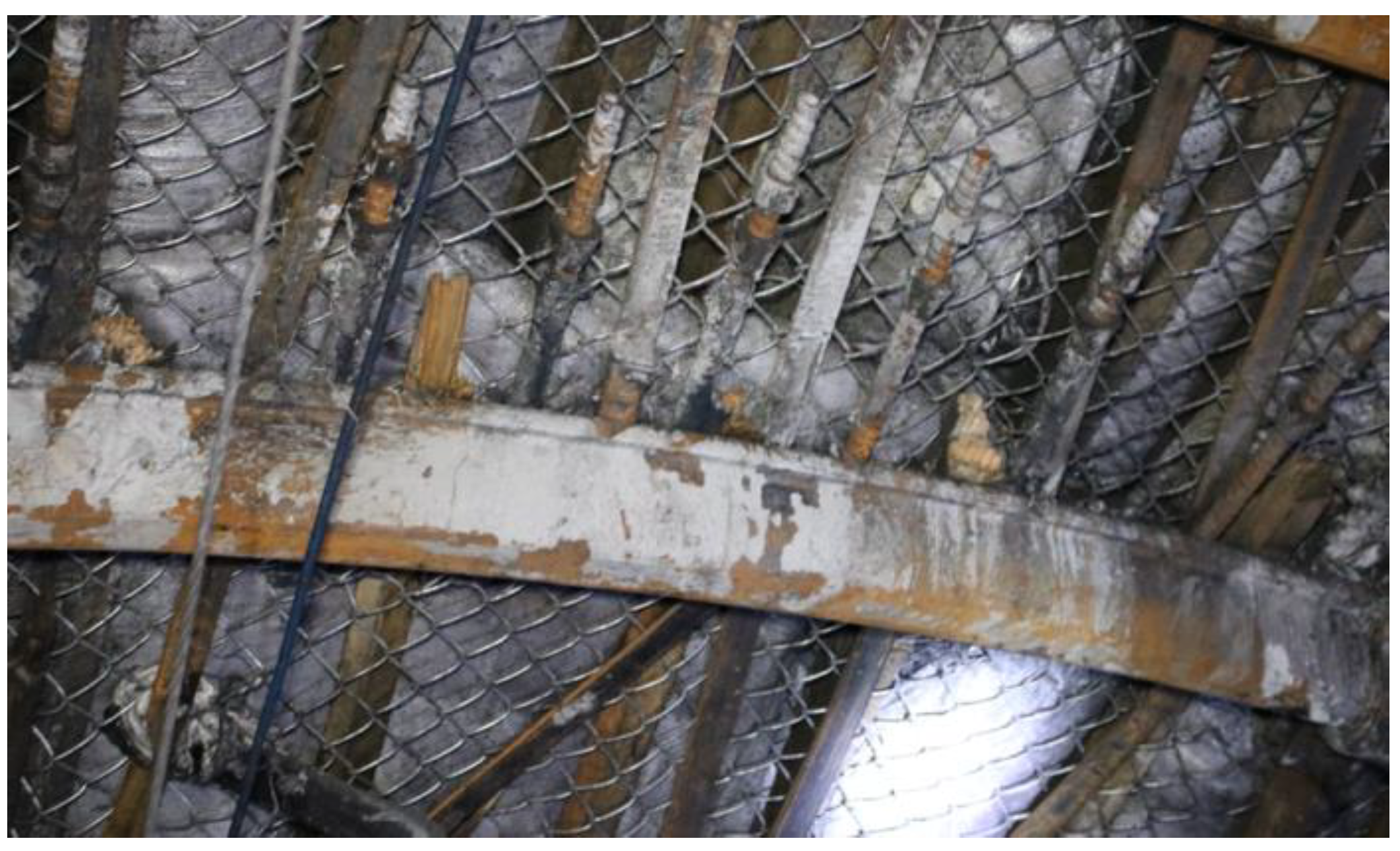
4.1. Metal Roof Skeleton

In the soft broken zone and the coal roadway excavation, the most common support methods are shed support, concrete arch support, and anchor mesh shotcrete combined with shed support. These support methods are labor intensive, high cost, and low efficiency. Because of the special geological conditions of the soft and thick coal roof in the Luling coal mine, problems encountered in the excavation process were slope and roof leakage. Although water injection during the process of excavation could alleviate the problem of side deviation to a certain extent, it had little effect on subsequent maintenance. Therefore, it was necessary to strengthen the support of the surrounding rock and maintain the stability. A row of pipe seam steel pipes could be constructed on the roof to form a “metal skeleton for advanced roof protection” and reinforcement of some areas affected by mining in front of the excavation. The schematic diagram of supporting section of metal roof skeleton is shown in Figure 10.
The construction process was as follows:
(1)
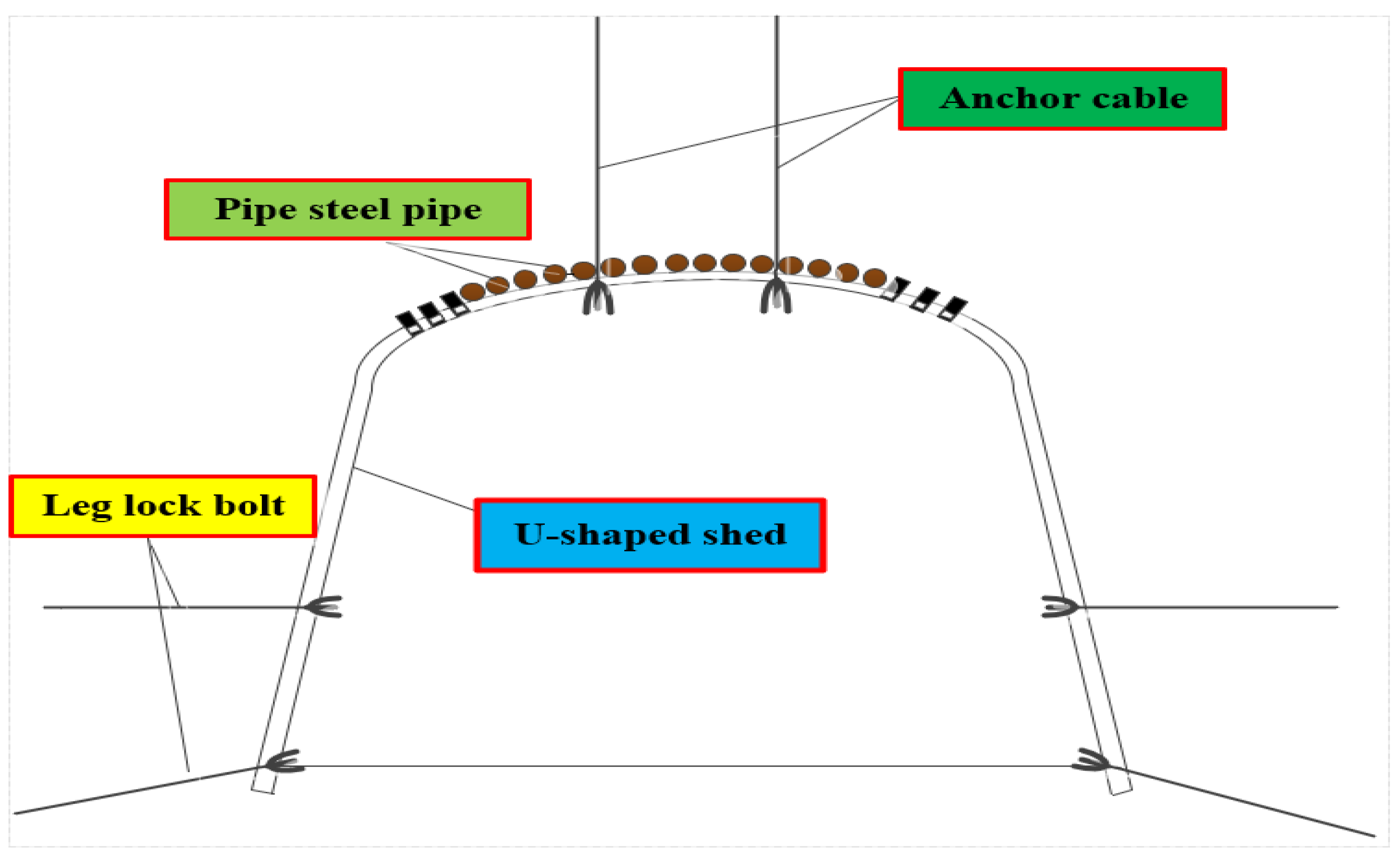
The two sides of the three-cores arch formed by the U-shaped shed beam were placed in the roadway side coal seam so that the top of the U-shaped shed beam was in contact with the coal seam. The two sides of the U-shaped shed beam were set in the rock stratum to improve the stability.
(2)
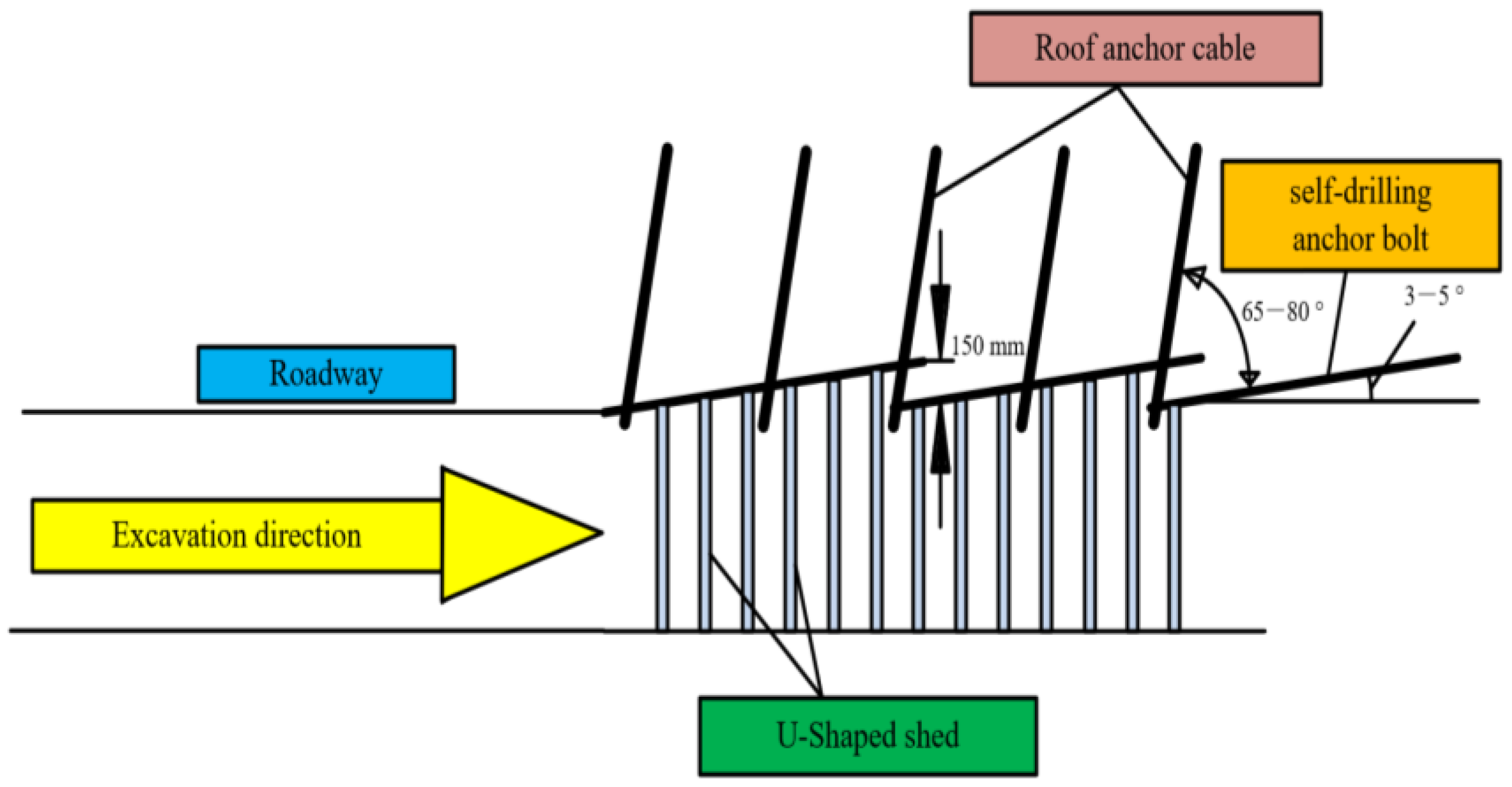
In the roof coal seam, the advanced skeleton anchor bolt was driven under its cover as support. The length of the advanced skeleton anchor bolt was 3 m per section. The specific requirements were as follows: The layout position of the advance skeleton anchor bolt was closed to the top of the head-on U-shaped shed beam, and the construction was carried out using an air drill, an anchor drill, and an air hammer. The spacing between the advanced skeleton anchor bolts was 100~150 mm. The skeleton angle and direction of all advanced skeleton anchor bolts were consistent to ensure that a plane was formed which was at an angle of 3~5° to the roadway roof. After construction with the advance skeleton anchor bolts was completed, the steel belt and anchor cable were used at its tail end for reinforcement, and the angle between the anchor cable and the advanced skeleton anchor bolt was 65~80°. When the advanced skeleton anchor bolt was erected forward, the U-shaped shed beam should be close to the upper metal skeleton. After construction of the stubble pressing position, the construction of the metal skeleton for the next section was carried out again under the adjacent U-shaped shed beam at the head, and the two adjacent U-shaped shed beams were erected by descending 150~200 mm in turn. Each group of advanced skeleton anchor bolts were constructed in a cycle of four sheds, and the steel belt and anchor bolts were used for secondary reinforcement between the third and the fourth sheds. The depth of the anchor end of the anchor cable into the stable rock stratum was not less than 1.5 m, and the row spacing between the anchor cables was 1200 mm × 1200 mm (split layout). The layout of the anchor rod, the anchor cable, and the steel belt with the advanced metal skeleton is shown in Figure 11.
The advanced metal skeleton for roof protection could effectively prevent roof leakage and caving and improve the integrity of the roof and the strength of the surrounding rock. It effectively resolved the problem effects caused by passive shed support and low tunneling efficiency. The process and method changed the traditional manual excavation and relied only on passive support. The small cycle manual wedge impact roof protection operation was also changed to a combination of large cycle hollow advanced skeleton and anchor bolted metal roof protection skeleton. The three-core arch of the U-shaped steel shed was well adapted to supporting large sections of the roadway under the thick coal roof and provide a guarantee for the transportation of fully mechanized mining equipment in the mining process. The implementation of an advanced skeleton for the roof improved the overall stability of the roadway, facilitated roof control, and effectively avoided the caving of loose coal in the roadway. It also achieved the integrated and rapid construction of main excavation processes, improved excavation efficiency under the thick coal roof, reduced labor intensity, and greatly improved mining safety.
The three-core arch U29 steel support was adopted. The specification was composed of three sections of U29 steel (one section of top beam and two sections of column legs). The arc length of the top beam was 4152 mm, the chord length was 4001 mm, the arc length of the curved section of column leg was 1128 mm, the length of the straight leg was 2573 mm, and the total length of column leg was 3901 mm. The bottom width was 5069 mm, the height was 3300 mm, and the specification of the welded iron shoe for the support shed leg was 150 mm × 150 mm × 20 mm, The double reactance net: length × width = 2000 mm × 1100 mm; the diamond mesh: length × width = 2500 mm × 700 mm; and the iron backplate, length × width × thickness = 800 mm × 40 mm × 7 mm. Iron backplates were used for each shed. The pull rod and iron back plate were made of the same material, The length of the pull rod was 450 mm, the width was 50 mm, and the thickness was 10 mm. The strength of anchor cable was 1860 MPa, with a breaking load of ≥353 kN. The length of the anchor cable was adjusted according to the coal thickness to ensure that the depth of the anchor cable into the rock was not less than 2 m. The roadway support diagram is shown in Figure 12.

4.2. Support Effect Evaluation

Following the use of water injection, advanced roof protection, and U-shaped shed support technology, statistics were collected and observations of surrounding rock and deformation of the rib were carried out during excavation. Data relating to the two sides of the roadway and roof subsidence were obtained. The effect on the roadway after the adoption of this support scheme is shown in Figure 13.
The deformation of the surrounding rock in the early stage of roadway excavation was very large, and it was basically in a stable state after 25 days of construction. The cumulative amount of roof convergence was 24.8 mm, and the cumulative amount of convergence of the two sides was 21.5 mm, both within the scope of safety and controllability. With this support method, the phenomena of roof leakage and rib spalling during roadway excavation were reduced, the construction progress of the roadway was accelerated, and the safety and efficiency of roadway construction were guaranteed.
The roadway supporting effect diagram is shown in Figure 14. From observation of the roadway excavation process, the phenomenon of spalling was effectively controlled, and the working environment of workers was greatly improved.

5. Conclusions

In this paper, numerical simulation, theoretical calculation, and site monitoring were combined to study the stress environment of surrounding rock, water injection process parameters, and support modes near the heading head of a soft and ultra-thick coal seam roadway. The main conclusions are as follows:
(1)
Based on numerical calculation, the central area of the roof and floor after roadway excavation was found to be the pressure relief area, and the stress concentration area appeared in the two bottom angles and sidewalls. The side showed asymmetric characteristics because of the influence of the coal seam dip angle.
(2)
From tests of the coal in the Luling coal mine, the moisture content of the coal was found to be 3.858%, which did not reach the optimum moisture content. The strength of coal could therefore be improved by appropriate water injection.
(3)
According to the engineering geological characteristics of the Luling coal mine, the construction technologies of water injection, metal steel pipe roof protection, and shed support were proposed, which enhanced the roof stability and accelerate the tunneling efficiency.
(4)
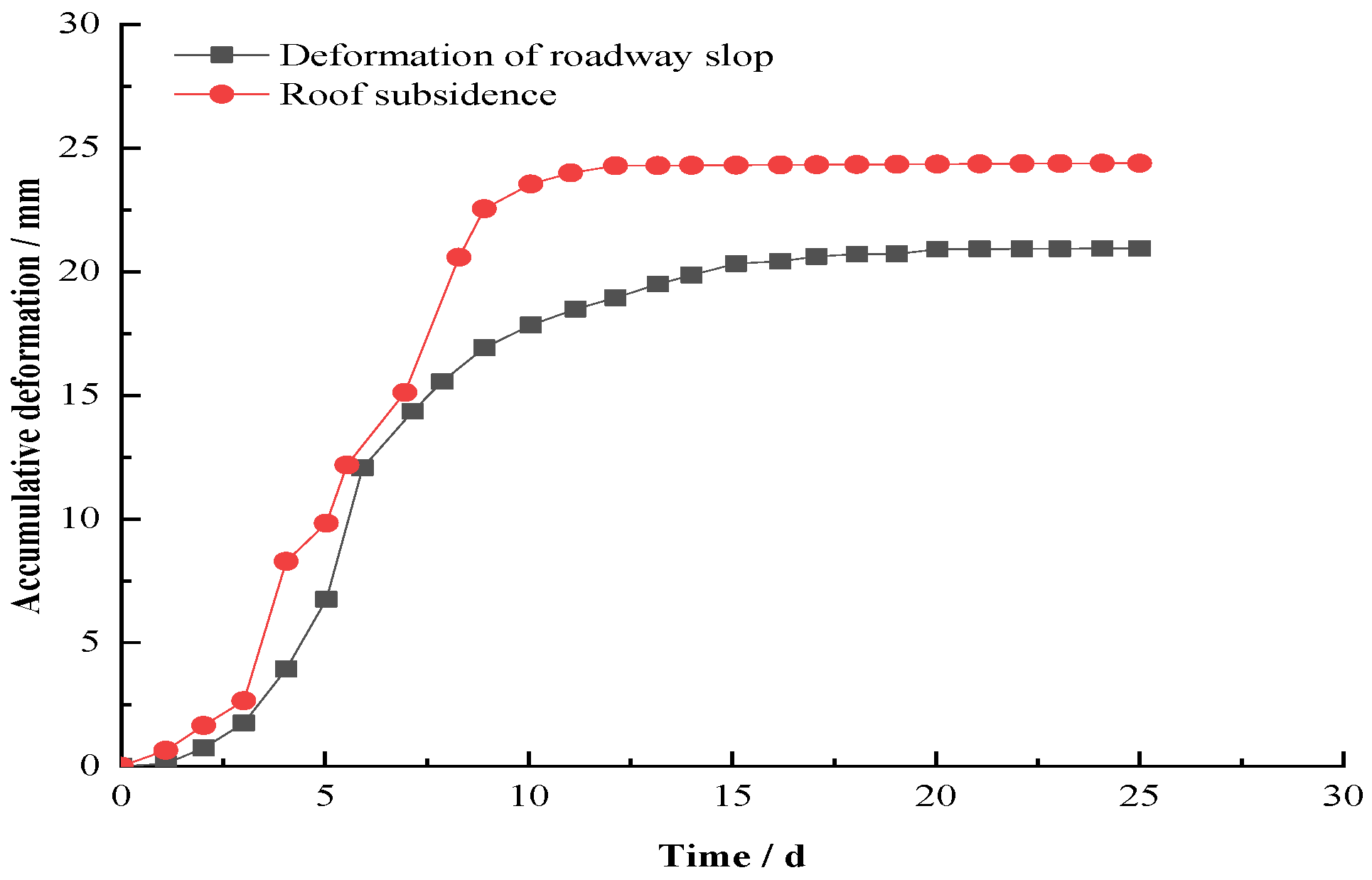
Site monitoring of the surrounding rock of roadway after support showed a maximum roof deformation of 24.8 mm. The two-side displacement was 21.5 mm. These data indicated that the surrounding rock deformation was in the safe range.

Author Contributions

Data curation, S.H., W.X. and S.Z.; Formal analysis, X.M., X.C. and G.L.; Methodology, G.Z. All authors have read and agreed to the published version of the manuscript.

Funding

This research was supported by the China Scholoarship Council (Nos. 202108340064), Supported by the National Natural Science Foundation of China(Nos. 51974009, 51774012, 51674008),Anhui Province academic and technical leader scientific research activity funds, university collaborative innovation project (GXXT-2021-075),Anhui Province Science and Technology Major Project (202203a07020011),National Talent Project(T2021137), Key Research and Development Projects in Anhui Province(No.201904a07020010),Leading Talents Project of Anhui Province’s “Special Support Plan”, Anhui Province Academic and Technical Leaders Re-search Activity Fund(2021), Funding project for the cultivation of outstanding and top-notch talents in colleges and universities (gxbjZD2016051),Huaibei City Science and Technology Major Program (No. Z2020005), Anhui Provincial Natural Science Foundation (No. 2008085QE222), China Postdoctoral Science Foundation (2021M691185), Postdoctoral Science Foundation of Anhui Province (No. 2021B513), Independent Research fund of The State Key Laboratory of Mining Response and Disaster Prevention and Control in Deep Coal Mines (Anhui University of Science and Technology, No. SKLMRDPC19ZZ012), Talent Fund of AUST (13200013), National Natural Science Youth Fund (Nos. 52004006).

Data Availability Statement

Data to support the findings of this study are available from the first author upon request.

Conflicts of Interest

The authors declare no conflict of interest.

References

  1. Cui, F.; Zhang, T.; Cheng, X. Research on Control of Rib Spalling Disaster in the Three-Soft Coal Seam. Shock Vib. 2021, 2021, 2404218. [Google Scholar] [CrossRef]
  2. Yuan, Y.; Zhu, C.; Wei, H. Study on rib spalling control of short wall drilling mining technology with a large mining height. Arab. J. Geosci. 2021, 14, 164. [Google Scholar] [CrossRef]
  3. Li, Z.H.; Shen, W. Sloughing mechanism and control of coal wall in high cutting fully-mechanized top coal caving mining face in ultra-thick seam. Coal Sci. Technol. 2016, 44, 45–51. [Google Scholar]
  4. Jin, Z.Y.; Zhang, Y.D.; Gao, L.S. Prevention Measures for Rib Spalling at Large Mining Height Working Face. Saf. Coal Mines 2013, 2013, 220–222. [Google Scholar]
  5. Likar, J.; Medved, M.; Lenart, M.; Mayer, J.; Malenković, V.; Jeromel, G.; Dervarič, E. Analysis of geomechanical changes in hanging wall caused by longwall multi top caving in coal mining. J. Min. Sci. 2012, 48, 135–145. [Google Scholar] [CrossRef]
  6. Li, S.H.; Zhang, F.C.; Zhang, Z. Design optimization of flat roof micro arch section of long-span coal roadway in Mengxi deep mine. Coal Technol. 2019, 38, 20–23. [Google Scholar] [CrossRef]
  7. Huang, X.W.; Yao, Z.S.; Cai, H.B.; Li, X.W.; Chen, H.Q. Performance evaluation of coaxial borehole heat exchangers considering ground non-uniformity based on analytical solutions. Int. J. Therm. Sci. 2021, 170, 107162. [Google Scholar] [CrossRef]
  8. Liu, S.; Yang, K.; Zhang, T. Rib Spalling 3D Model for Soft Coal Seam Faces with Large Mining Height in Protective Seam Mining: Theoretical and Numerical Analyses. Geofluids 2020, 2020, 8828844. [Google Scholar] [CrossRef]
  9. Li, C.; Kang, T.; Li, X. Theoretical Investigation of the Sliding Instability and Caving Depth of Coal Wall Workface Based on the Bishop Strip Method. Adv. Civ. Eng. 2019, 2019, 3065930. [Google Scholar] [CrossRef]
  10. Fu, Y.G.; Li, Y.M.; Xu, X.S. Study on Mechanism of Rib Spalling in Large Cutting Height Rise Mining Face in Soft Thick Seam. Coal Sci. Technol. 2014, 42, 15–18. [Google Scholar]
  11. Wang, J.C. Mechanism of the rib spalling and the controlling in the very soft coal seam. J. China Coal Soc. 2017, 32, 785–788. [Google Scholar]
  12. Yang, K.; He, X.; Liu, S.; Lu, W. Rib spalling mechanism and control with fully mechanized longwall mining in large inclination “three-soft” thick coal seam under closed distance mined gob. J. Min. Saf. Eng. 2016, 33, 611–617. [Google Scholar]
  13. Guo, J.S.; Ma, L.Q.; Wang, Y.; Wang, F.T. Hanging Wall Pressure Relief Mechanism of Horizontal Section Top-Coal Caving Face and Its Application-A Case Study of the Urumqi Coalfield. Energies 2017, 10, 1371. [Google Scholar] [CrossRef]
  14. Liu, Z.G.; Cao, A.Y.; Guo, X.S.; Li, J.X. Deep-hole water injection technology of strong impact tendency coal seam—a case study in Tangkou coal mine. Arab. J. Geosci. 2018, 11, 12. [Google Scholar] [CrossRef]
  15. Liu, Z.; Wang, W.Y.; Yang, H.; Yu, S.J.; Xin, L. Experimental Study on the Fractal Pattern of a Coal Body Pore Structure Around a Water Injection Bore. J. Energy Resour. Technol. 2020, 142, 012302. [Google Scholar] [CrossRef]
  16. Yan, J.J.; Wang, F.; Li, Y.C.; Gao, Y.B.; Li, Z.G.; Liu, H.W. A Feasibility Study of Coal Seam Water Injection Processes: The Effects of Coal Porosity and Mass Flow Rates of Injected Water on Wetting Radii. Energy Fuels 2020, 34, 16956–16967. [Google Scholar] [CrossRef]
  17. Yang, R.; Zhu, Y.; Zhu, X. Discussions on Some Security Mining Problems of Fully-Mechanized Top Coal Mining in “Three Soft” Large Inclined Angle Working Face. Procedia Eng. 2011, 26, 1144–1149. [Google Scholar]
  18. Liu, C.Y.; Zhao, G.M.; Xu, W.S.; Meng, X.R.; Huang, S.J.; Zhou, J.; Wang, Y.K. Experimental investigation on failure process and spatio-temporal evolution of rockburst in granite with a prefabricated circular hole. J. Cent. South Univ. 2020, 27, 2930–2944. [Google Scholar] [CrossRef]
  19. Chen, W.M.; Nie, W.; Zhou, G.; Yu, Y.B.; Ma, Y.Y.; Xue, J. Research and practice on fluctuation water injection technology at low permeability coal seam. Saf. Sci. 2012, 50, 851–856. [Google Scholar] [CrossRef]
  20. Dong, L.J.; Chen, Y.C.; Sun, D.Y.; Zhang, Y.H. I Implications for rock instability precursors and principal stress direction from rock acoustic experiments. Int. J. Min. Sci. Technol. 2021, 31, 789–798. [Google Scholar] [CrossRef]
  21. Perera, M.S.A.; Ranjith, P.G.; Choi, S.K.; Bouazza, A. A parametric study of coal mass and cap rock behavior and carbon dioxide flow during and after carbon dioxide injection. Fuel 2013, 106, 129–138. [Google Scholar] [CrossRef]
  22. Wei, J.P.; Jiang, W.; Si, L.L.; Xu, X.Y.; Wen, Z.H. Experimental research of the surfactant effect on seepage law in coal seam water injection. J. Nat. Gas Sci. Eng. 2022, 103, 104612. [Google Scholar] [CrossRef]
  23. Wang, G.; Wang, E.M.; Huang, Q.M.; Li, S.P. Effects of cationic and anionic surfactants on long flame coal seam water injection. Fuel 2022, 309, 122233. [Google Scholar] [CrossRef]
  24. Hao, J.Y.; Hu, X.M.; Zhao, Y.Y.; Shao, Z.; Cheng, W.M.; Zhu, S.C.; Song, C.Y.; Zhu, F.S. Improvement of wettability of coal seams in water injection via co-deposition of polydopamine and polyacrylamide. Colloids Surf. A Physicochem. Eng. Asp. 2022, 636, 128112. [Google Scholar]
  25. Sun, J.; Zhou, G.; Wang, C.M.; Liu, R.L.; Miao, Y.N. Performance comparison analysis of high-efficiency wetting enhancers for coal seam water injection. Process Saf. Environ. Prot. 2021, 147, 320–333. [Google Scholar] [CrossRef]
  26. Wei, K. Study on Prevention Technology of Rib Spalling of Coal Wall Water Injection in “Three Soft” Thick Coal Seam. Master’s Thesis, China University of Mining and Technology, Beijing, China, 2018. [Google Scholar]
Figure 1. Section sketch of the heading roadway.
Processes 10 01835 g001
Figure 2. Numerical calculation of 3D model.
Processes 10 01835 g002
Figure 3. The zz-stress contour in the different range of heading faces.
Processes 10 01835 g003
Figure 4. The xx-stress contour in the different range of heading faces.
Processes 10 01835 g004
Figure 5. The xz-stress contour in the different range of heading faces.
Processes 10 01835 g005
Figure 6. The plastic zone contour in the different range of heading faces.
Processes 10 01835 g006
Figure 7. Electrothermal drying oven.
Processes 10 01835 g007
Figure 8. Test weighing pictures.
Processes 10 01835 g008
Figure 9. Wetting modes of water and coal.
Processes 10 01835 g009
Figure 10. Schematic diagram of supporting section of metal roof skeleton.
Processes 10 01835 g010
Figure 11. Reinforcement layout of the advanced metal skeleton and roof.
Processes 10 01835 g011
Figure 12. The site construction supports drawing of metal roof skeleton.
Processes 10 01835 g012
Figure 13. Deformation of the surrounding rock.
Processes 10 01835 g013
Figure 14. Roadway supporting effect diagram.
Processes 10 01835 g014
Table 1. Coal and rock mass parameters.
LithologyBulk Modulus
/GPa
Elastic Modulus
/GPa
Cohesive
/MPa
Internal Friction Angle/°Tensile Strength
/MPa
Volumetric Weight
/N·m−3
Sandstone1.3331.0002.78362.202673
Mudstone6.0803.4701.229.80.612261
Siltstone1.0838.1252.75381.842461
Fine-sandstone2.2101.1532.5322.402730
8# and 9# coal4.2942.7021.25321.151380
Publisher’s Note: MDPI stays neutral with regard to jurisdictional claims in published maps and institutional affiliations.

