Article

The Split Flow Process of CO2 Capture with Aqueous Ammonia Using the eNRTL Model

1
Department of Chemical Engineering, Kyung-Hee University, Yongin 17104, Korea
2
Department of Chemical Engineering, Dong-A University, Busan 49315, Korea
*
Author to whom correspondence should be addressed.
Processes 2022, 10(9), 1839; https://doi.org/10.3390/pr10091839
Submission received: 28 July 2022 / Revised: 3 September 2022 / Accepted: 8 September 2022 / Published: 13 September 2022

Abstract

:
Carbon Capture and Storage (CCS) technology has attracted increasing attention as global climate change accelerates. Carbon dioxide removal processes under development include pressure swing adsorption (PSA) and chemical absorption using amine solvents. In this paper, an ammonia solvent, which is relatively inexpensive and has good material properties, was used instead of amines in the carbon dioxide removal process simulation as a chemical absorption method. This simulation used the eNRTL thermodynamics model which has the advantage of predicting ions in the liquid phase in Aspen Plus. A case study (Case Study 1) was conducted to verify the validity of the thermodynamic model. The purpose of this research was to find the operating conditions to eliminate more than 90% of the carbon dioxide contained in the flue gas from coal-fired power stations, and to lower heat duty and operating cost conditions. A second case study (Case Study 2) was conducted to find the operating conditions by comparing various process operating conditions. Additionally, this paper determined lower operating cost conditions by manipulating the amount of steam and cooling water. The results showed that the heater’s outlet temperature should be set at under 80 ℃ to lower the operating costs. As a result of changing the flow rate of the side stream of the split flow process, energy consumption was reduced when compared to the conventional flow process. It was shown that the split flow is a superior process with 10.24% less energy use than the conventional flow. In this study, the split flow process achieved an energy saving advantage when compared to the conventional flow process, and a carbon dioxide removal rate of 95% was achieved.

1. Introduction

Carbon dioxide, the main cause of the greenhouse effect, has attracted much attention in recent years. Thermal power plants that consume large amounts of coal are one of the main causes of the greenhouse effect, but it is difficult to replace them with alternative power plants due to their high energy production efficiency. For this reason, the removal process of flue gas including carbon dioxide from coal-fired power plants has been widely studied [1].
The International Energy Agency (IEA) reported that CO2 emissions dropped by 5.8% during the COVID-19 pandemic, and coal-based CO2 emissions declined by 0.6 Gt CO2. However, coal-based electricity generation contributes 35% of production, which is still larger than renewables, oil, and nuclear [2]. Further, they have identified that Carbon Capture and Storage (CCS) technology will be essential to meet the global goal of limiting global temperature increase. At least 90% of CO2 could be captured from the power plant and energy industries [3]. More than 80% of energy comes from the combustion of fossil fuels, which contributes to global warming. However, after CO2-capturing processes, CO2 can be turned into fuels such as methanol, formic acid, dimethyl carbonate, and methyl formate [4]. There are various ways to capture carbon dioxide, including absorption, adsorption, membrane, cryogenic, and CO2/O2 combustion. Absorption is divided into two methods: chemical and physical absorption. Chemical absorption uses an aqueous solution, such as of amines or sodium hydroxide and sodium carbonate. Absorption has the advantage that the solvent is regenerated and returned to a continuous carbon dioxide removal process [5]. CCS technology still faces some challenges, however. Large scale CCS has a high energy demand, leading to high operating costs. Optimization of the process is required to reduce energy demands and cost [6]. Various CO2 capture processes have been developed with amine solvents, such as MEA (monoethanolamine). However, MEA has drawbacks: the high solvent cost, thermal degradation, and low CO2 absorption efficiency. Therefore, NH3 has been identified as a new absorption solvent. Comparisons of amines and ammonia as CO2 capture solvents have been undertaken. By theoretical values, NH3 can capture carbon dioxide twice as effectively as MEA [7]. Dave et al. [8] showed that 5 wt% ammonia solvent has at least 23% to 29% lower reboiler duty than 30 wt% amine solvent in carbon dioxide capture.
Shanbaz et al. [9] simulated the CO2 capture process with a CaO solvent in syngas production from steam gasification. Riva et al. [10] simulated the post-combustion CO2 capture process by chemical absorption using ionic liquid. Sinaki et al. [11] simulated CO2 capture with the MEA solvent from the post-combustion of mazut using Aspen Hysys. Darde et al. [12] simulated the Chilled Ammonia Process (CAP) with the Extended UNIQUAC model. They focused on absorption at low temperatures to increase CO2 loading. Li et al. [13] simulated the inter-heating process and rich-split process to reduce reboiler heat duty at a large-scale coal-fired power station. Niu et al. [14] studied the CO2 capture process with aqueous ammonia using the eNRTL model, and simulated the CO2 capture system and NH3 abatement system. Ishaq et al. [15] simulated the post-combustion CO2 capture process with aqueous ammonia and a split flow arrangement using the eNRTL model. They compared the results of the absorber height and split fraction, which affects reboiler heat duty. Mathias et al. [16] conducted an analysis and quantitative evaluation on chilled ammonia processes (CAP) with a thermodynamics analysis and process simulation. The analysis can provide a way to predict operational problems. The evaluation revealed how the process performance changes as operating conditions change, and identified the optimal conditions to operate the process. Song et al. [17] studied a carbon dioxide capture process with PTSA (Pressure–Temperature Swing Adsorption). In the study, an advanced PTSA method was used which involved an integrated chemical heat transformer and pressure recovery. An advanced PTSA method was simulated with PRO/II software, and it resulted in 40% energy savings when compared to conventional PTSA methods. The carbon dioxide removal rates and energy consumption of recent carbon dioxide removal processes are summarized in Table 1.
Ullah et al. [18] studied a CO2 capture process with an ammonia solvent, and the RVC (Rich Vapor Compression) process and the CSS (Cold Solvent Split) process were combined to significantly increase energy consumption efficiency when compared to the existing CO2 capture process. Ullah et al. [19] studied an additional energy-saving process by combining the RVC process with the LVC (Lean Vapor Compression) process and the CSS process. Jiang et al. [20] achieved energy savings through the Cold Rich Split process with ammonia. It achieved a 34% reduction effect when compared to the existing ammonia process and a 44% reduction effect compared to the MEA process. A follow-up study in Jiang et al. [21] proceeded to capture CO2 in the PZ (Piperazine) + ammonia process by adding PZ to the ammonia-based CO2 capture process. By applying the CSS process to this process, energy was reduced by 20% when compared to the MEA-based CO2 capture process. Liu et al. [22] compared the energy efficiency with the inter-heating process, rich-split process, and combined process (inter-heating + rich split). The combined process showed better energy efficiency than other two processes. These are the studies that increase energy efficiency in CO2 capture processes by applying split flow.
In this paper, we simulated the split flow CO2 removal process with an ammonia solvent, applying the eNRTL thermodynamics model in Aspen Plus to find the operating conditions to improve the consumption of reboiler heat duty, as shown in Table 1.
Case Study 1 analyzed the carbon dioxide capture process of a cement plant to verify the eNRTL model, and Case Study 2 simulated the carbon dioxide capture process by changing various process operating conditions.

2. Process Design

This simulation was based on flue gas from a 500 MW (megawatt) coal-fired power station as a feed. The specifications of flue gas from the 500 MW coal-fired power station are shown in Table 2 [23]. The fixed operating conditions of the carbon dioxide removal process in this study are summarized in Table 3.
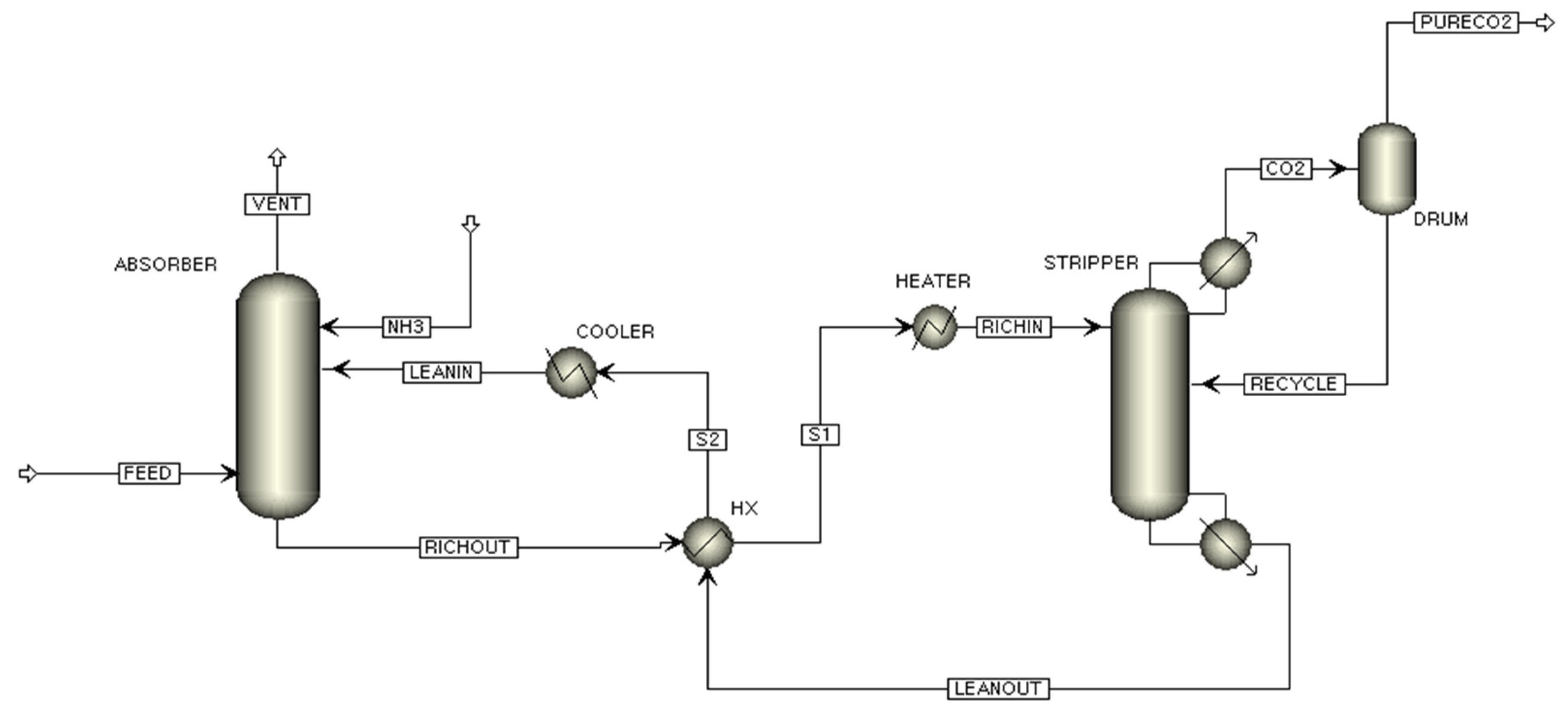
The flowsheet of the conventional flow CO2 capture process of this study is shown in Figure 1. The CO2 capture process can be divided into two parts: the CO2 capture part and NH3 abatement part. The flue gas enters the CO2 absorber and is absorbed by contacting the NH3 solution. The overhead stream from the CO2 absorber goes to the NH3 abatement part to separate N2 and NH3. The separated NH3 stream is recycled to the CO2 capture part and is mixed with the CO2 lean stream. An absorber bottom stream, which is called the rich stream, goes to the CO2 stripper to remove CO2 from the absorbed NH3 solution. The lean stream from the bottom of the CO2 stripper is fed to the top of the CO2 absorber. A flowsheet of the split flow CO2 capture process is shown in Figure 2. The difference of this system from the conventional CO2 capture process is the side stream from the CO2 stripper, which is fed into the CO2 absorber. Using the split-flow process has the advantage of reducing energy usage in the stripper [24,25].
The electrolyte Non-Random Two-Liquid (eNRTL) thermodynamics model helps to predict ionic species in liquid phases as a function of the equilibrium of CO2 solubility and temperature [26]. Dash et al. [27] carried out an experiment on CO2 solubility in AMP (2-amino-2-methyl-1-propanol) using the eNRTL model. The model theory was developed to correlate with and predict the vapor–liquid equilibrium (VLE) for CO2 in aqueous AMP. The model’s prediction has shown good agreement with the experimental data. The model prediction of eNRTL thermodynamics was conducted by Yu et al. [28], based on post-combustion capture using aqueous ammonia. The prediction showed the technical feasibility of the process at a low ammonia concentration. In this study, the eNRTL model was applied to the split flow CO2-capturing process with the Aspen Plus simulation. Niu et al. [29] conducted a pilot plant at the laboratory scale for CO2 capture by aqueous ammonia. In addition, an Aspen Plus simulation was performed, and the simulation results and the experimental results showed good agreement.
Table 3. Fixed operating conditions [30].
ParameterValue
Absorber
Feed temperature/pressure (flue gas)50 °C/1.0133 bar
Number of stages6
Pressure1.0133 bar
Stripper
Number of stages20
Pressure1.0133 bar
Ammonia solution
NH3 solution temperature/pressure25 °C/1.0133 bar
NH3 mass fraction7%
The CO2 capture process using aqueous amine solution has already been researched previously. Due to disadvantages such as thermal degradation and the high absorbent cost of amine solvents, Ciferno et al. [31] showed that 7 wt% aqueous ammonia can be used in the CO2 capture process, and compared the cost and energy with 30 wt% MEA. The qualitative comparison of amines and ammonia is shown in Table 4 [32]. Ammonia solvents have twice the CO2 capture capacity and half the regeneration energy compared to amine solvents. In addition, it has the advantages of low thermal degradation and low absorbent cost; however, it also has the disadvantage of high volatility and the need for a regeneration process. For the above reasons, this paper used aqueous ammonia solution for the CO2 capture process.
The simulation was carried out assuming that the operating conditions of the process included atmospheric pressure, except for salt formation. The limitations of this simulation are that the purity of the pure CO2 stream is slightly low, about 96%, and an abatement process is required due to the limitation of ammonia emission into the atmosphere, however, the recycle stream was not included in the simulation because the process was not designed.

3. Process Simulation

A process simulation was carried out to find the operating conditions of the process in order to reduce energy and operating costs.

3.1. Case Study 1

In Case Study 1, to verify the validity of the eNRTL thermodynamic model, the results of the actual carbon dioxide removal process [34,35] and the simulation results using Aspen Plus were compared. The Aspen Plus simulation was performed in the same way for the feed gas used in the CO2 capture process from the cement plant, and the results are compared and summarized in Table 5. Table 6 and Table 7 compare the stream data of the carbon dioxide capture process of the cement plant and the stream data of the Aspen Plus simulation result, respectively. Simulation data in Table 5 and the data in Table 7 are the result values obtained by simulating with Aspen Plus in the same way as the Reference 32 conditions. The tables show that comparable results are within the error range. Figure 3 shows the comparison between the experimental data [36] and the eNRTL thermodynamics model of Aspen Plus. The condition of the experimental data was 80 °C (353.15 K), which is the closest to the range of operating conditions in our simulation.

3.2. Case Study 2

3.2.1. CO2 Stripper

The operation conditions of the CO2 stripper, which removes the CO2 absorbed in the ammonia solution, were compared with the CO2 removal rate when the conditions of the reflux ratio and the reboiler duty were changed.
The CO2 removal rate increased as the reflux ratio decreased and reboiler duty increased. Although setting the reflux ratio to a low value seems advantageous, the condenser duty of the CO2 stripper increased as the reflux ratio decreased. The comparison of the reflux ratio and CO2 capture, as well as the comparison of the reboiler duty and CO2 capture, are shown in Tables S1 and S2, respectively. Tables S1 and S2 are included in supplementary materials.

3.2.2. Ammonia

Dave et al. [8] compared the regeneration energy with the ammonia mass fraction and temperature of the ammonia solution. The corresponding research results were applied to this simulation to confirm the results.
The 5 wt% ammonia solution process with the 7 wt% ammonia solution process achieved the same amount of carbon dioxide removal. Increasing the NH3 mass fraction from 5 wt% to 7 wt% reduced the NH3 solution amount, the NH3 solvent amount and the reboiler duty of the CO2 stripper. The 7 wt% ammonia solution was the superior operating condition. Concentrations greater than this 7 wt% process were not preferred because of the minimal NH3 loss and reboiler duty [6]. The results of changes in the temperature of the NH3 solution were also compared. The reboiler duty and ammonia mass fraction were fixed. The results of each temperature differed slightly, but because of the NH3 solution cooling (or heating at the 30 °C) duty, the total heat duty was increased. As a result, 25 °C NH3 solution was selected as the advisable operating condition. A comparison of the heat duty of different ammonia mass fractions and temperatures is shown in Table 8 and Table 9, respectively.

3.2.3. Semi-Lean Stream

This study compared the CO2 removal rate with the feed stage of the semi-lean stream and the flow rate of the semi-lean stream. The carbon dioxide removal rate becomes higher as the feed stage of the semi-lean stream becomes closer to the third stage. The comparison of the semi-lean feed stage is shown in Table S3. Table S3 is included in supplementary materials. The simulation was controlled the flow rate of the semi-lean stream, which is the side stream of the CO2 stripping column. A comparison of the reboiler heat duty was conducted at the 90% removal rate and the 95% removal rate, as the flow rate of side stream changed. In both removal rates, when the flow rate of the side stream was 5 kmol/s, the savings in reboiler heat duty were the largest when compared to those of conventional flow. At the 90% CO2 removal rate, the split flow showed an energy saving of 10.24% when compared to the conventional flow, and at 95%, the split flow showed an energy saving of 7.14% when compared to the conventional flow. Results of the reboiler heat duty as a change of the flow rate of the side stream are in Table 10 and Table 11.

3.2.4. Pre-Heater

The rich stream, which absorbs carbon dioxide from the CO2 absorber, undergoes pre-heating before entering the CO2 stripper. In changing the condition of the pre-heater, we compared what changes were made. When compared to the presence or absence of the pre-heater, the total heat duty does not change as much as the pre-heater heat duty decreases the CO2 stripper condenser duty. Table 12 shows a change in the pre-heater’s outlet temperature when the results are compared. The condenser duty decreased and heater duty increased as the temperature of the heater increased. The total duty was maintained regardless of temperature. From an economic perspective, a comparison of the steam used for the heater and cooling water used for the condenser was conducted. The steam price is $1.9 × 10⁻⁶/kJ and the cooling water price is $2.12 × 10⁻⁷/kJ, therefore it is advantageous to set the heater temperature to under 80 °C. The steam price and cooling water price are quoted from Aspen Plus.

4. Results

The simulation presented here determined the operating conditions when the CO2 removal process using aqueous ammonia has a CO2 removal rate of 90%. Based on the above various operating conditions, such as the operating conditions of stripping column, conditions of the aqueous ammonia solvent and the flow rate of side stream, the reboiler heat duty produced a result of 1298.98 kJ/kgCO2 when the CO2 removal rate was 90% and 1705.35 kJ/kgCO2 at 95% removal rate. The operating conditions of the process are shown in Table S4. Table S4 is included in supplementary materials.
This paper compared the energy consumption per kgCO2 of conventional flow and split flow at the same CO2 removal rate to show that the split flow process is the improved process. Ishaq et al. [15] and Bae et al. [37] showed that split flow has a lower reboiler heat duty than conventional flow. The results of this paper were similar to the results of the previous studies. Therefore, the simulation applied split flow and compared the results. We compared the energy consumption of the conventional flow and split flow process with a rate of 90% and 95%, respectively. For 90% carbon dioxide removal, split flow had a 10.24% lower reboiler heat duty than the conventional flow process when the flow rate of side stream is 5 kmol/s. This figure represents an operating cost savings of $838,457 per year, calculated as a utility cost of Aspen Plus. At 95% carbon dioxide removal, split flow had a 7.14% lower reboiler heat duty than conventional flow when the flow rate was the same as the 90% removal rate. The results showed that the split flow process had a lower reboiler duty than the conventional flow process at both carbon dioxide removal rates. The results are summarized in Table 13. In addition, this paper compared the preheater outlet temperature to reduce the operating cost of preheater. When the temperature of the stream entering the stripping column is lower than the temperature of the stripping column top product stream, the total duty is constant, but when it is high, additional costs are incurred by using cooling water. For this reason, it is advantageous to reduce operating costs by setting the temperature of the preheater installed in front of the stripping column to 80 °C or less.
The simulation results were compared to other papers using aqueous ammonia with a 90% CO2 removal rate. The energy consumption per kgCO2 was improved when compared to Darde et al. [12] and Ishaq et al. [15].

5. Conclusions

The simulation of the CO2 capture process of flue gas from a 500 MW coal-fired power station was performed with various operating conditions with aqueous ammonia solution using the eNRTL model. Operating conditions were determined by changing the values of the reboiler duty, reflux ratio, and temperature and mass fraction of ammonia solution according to the CO2 removal rate. The CO2 removal rate increased as the reboiler duty increased, and the reflux ratio showed the opposite trend. It was confirmed that the use of a 7% ammonia mass fraction resulted in energy savings by comparing the reboiler heat duty at same carbon dioxide removal rate. The comparison of reboiler heat duty through the temperature change of ammonia solution was performed. The reboiler heat duty was the lowest when other conditions were the same at room temperature of 25 °C, and at other temperature conditions, heating duty or cooling duty was required, so 25 °C was an appropriate operating condition. By changing the temperature of the pre-heater of the CO2 stripper, we found that setting the temperature to lower than 80 °C, in terms of the process operating cost, was beneficial. The operating conditions at a 90% carbon dioxide removal rate and 90% removal rate were found as a result. The conventional flow process and split flow process showed an energy consumption difference when the carbon dioxide removal rate was 90%, which persisted if the carbon dioxide removal rate was 95% by changing the flow rate of the side stream. When these results were observed by changing the flow rate of the side stream of the stripping column, the difference in energy consumption peaked at 5 kmol/s of flow rate, and then the difference decreased as it increased. It was confirmed that the split flow is more beneficial in terms of energy than the conventional flow, based on the same results as the previous research results. As a result of the study, the operating conditions of the process aiming for the carbon dioxide removal rate of 95% were confirmed, and 10.24% and 7.14% energy savings were obtained in the process with the removal rate of 90% and 95% compared to the conventional flow process, respectively. We developed operating conditions for the split-flow CO2 capture process with a reduced energy consumption per kgCO2 by at least 26.19% and up to 36.63%, compared to other papers, with a 90% CO2 removal rate.

Supplementary Materials

The following supporting information can be downloaded at: https://www.mdpi.com/article/10.3390/pr10091839/s1, Table S1: Comparison of the reflux ratio and CO2 capture; Table S2: Comparison of the reboiler duty and CO2 capture; Table S3: Comparison of Semi-lean feed stage; Table S4: Operating condition for 90% removal rate; Table S5: Material balance table.

Author Contributions

Supervision, S.Y.K.; Writing—original draft, S.W.J. and S.Y.K.; Writing—review & editing, B.L. and S.Y.K. All authors have read and agreed to the published version of the manuscript.

Funding

This research received no external funding.

Data Availability Statement

Data supporting the results of the research can be found in the article.

Acknowledgments

Sung Young Kim acknowledges support from the National Research Foundation of Korea (NRF) grant, funded by the Korean government (MSIT) (No. 2019R1G1002241).

Conflicts of Interest

The authors declare no conflict of interest.

References

  1. IEA. World Energy Outlook 2011; IEA/OCED: Paris, France, 2011. [Google Scholar]
  2. Global Energy Review: CO2 Emissions in 2020; IEA: Paris, France, 2021.
  3. World Energy Outlook; IEA: Paris, France, 2013.
  4. Yu, K.M.K.; Curcic, I.; Gabriel, J.; Tsang, S.C.E. Recent advances in CO2 capture and utilization. ChemSusChem. 2008, 1, 893. [Google Scholar] [CrossRef]
  5. Meisen, A.; Shuai, X. Research and development issues in CO2 capture. Energy Convers. Manag. 1997, 38, S37–S42. [Google Scholar] [CrossRef]
  6. Zahra, M.A. Carbon Dioxide Capture from Flue Gas: Development and Evaluation of Existing and Novel Process Concepts; PrintPartners Ipskamp BV: Enschede, The Netherlands, 2009. [Google Scholar]
  7. Yeh, A.C.; Bai, H. Comparison of ammonia and monoethanolamine solvents to reduce CO2 greenhouse gas emissions. Sci. Total Environ. 1999, 228, 2–3. [Google Scholar] [CrossRef]
  8. Dave, N.; Do, T.; Puxty, G.; Rowland, R.; Feron, P.H.M.; Attalla, M.I. CO2 capture by aqueous amines and aqueous ammonia–A Comparison. Energy Procedia 2009, 1, 949. [Google Scholar] [CrossRef]
  9. Shahbaz, M.; Yusup, S.; Inayat, A.; Ammar, M.; Patrick, D.O.; Pratama, A.; Naqvi, S.R. Syngas production from steam gasification of palm kernel shell with subsequent CO2 capture using CaO sorbent: An aspen plus modeling. Energy Fuels 2017, 11, 12350. [Google Scholar] [CrossRef]
  10. de Riva, J.; Ferro, V.; Moya, C.; Stadtherr, M.A.; Brennecke, J.F.; Palomar, J. Aspen Plus supported analysis of the post-combustion CO2 capture by chemical absorption using the [P2228][CNPyr] and [P66614][CNPyr]AHA Ionic Liquids. Int. J. Greenh. Gas Control. 2018, 78, 94. [Google Scholar] [CrossRef]
  11. Sinaki, S.Y.; Atabi, F.; Panjeshahi, M.H.; Moattar, F. Post-combustion of mazut with CO2 capture using aspen hysys. Pet. Sci. Tech. 2019, 37, 2122. [Google Scholar] [CrossRef]
  12. Darde, V.; Thomsen, K.; van Well, W.J.M.; Stenby, E.H. Chilled ammonia process for CO2 capture. Energy Procedia 2009, 1, 1035. [Google Scholar] [CrossRef]
  13. Li, K.; Yu, H.; Feron, P.; Wardhaugh, L.; Tade, M. Techno-economic assessment of stripping modifications in an ammonia-based post-combustion capture process. Int. J. Greenh. Gas Control. 2016, 53, 319. [Google Scholar] [CrossRef]
  14. Niu, Z.; Guo, Y.; Zeng, Q.; Lin, W. A novel process for capturing carbon dioxide using aqueous ammonia. Fuel Processing Technol. 2013, 108, 154. [Google Scholar] [CrossRef]
  15. Ishaq, H.; Ali, U.; Sher, F.; Anus, M.; Imran, M. Process analysis of improved process modifications for ammonia-based post-combustion CO2 capture. J. Environ. Chem. Eng. 2021, 9, 104928. [Google Scholar] [CrossRef]
  16. Mathias, P.; Satish Reddy, J.; O’Connell, P. Quantitative evaluation of the chilled-ammonia process for CO2 capture using thermodynamic analysis and process simulation. Int. J. Greenh. Gas Control. 2010, 4, 174. [Google Scholar] [CrossRef]
  17. Zhang, J.; Chen, Y.; Zhang, S.; Zhang, Y.; Xu, L.; Qu, Z.; Song, G. Comprehensive assessment and hierarchical management of the sustainable utilization of urban water resources based on catastrophe theory. J. Taiwan Inst. Chem. Eng. 2016, 64, 69. [Google Scholar]
  18. Ullah, A.; Soomro, M.I.; Kim, W.-S. Analysis of a rich vapor compression method for an ammonia-based CO2 capture process and freshwater production using membrane distillation technology. Chem. Eng. Res. Des. 2019, 147, 244. [Google Scholar] [CrossRef]
  19. Ullah, A.; Soomro, M.I.; Kim, W.-S. Ammonia-based CO2 capture parameters optimization and analysis of lean and rich vapor compression processes. Sep. Purif. Technol. 2019, 217, 8. [Google Scholar] [CrossRef]
  20. Jiang, K.; Li, K.; Yu, H.; Chen, Z.; Wardhaugh, L.; Feron, P. Advancement of ammonia based post-combustion CO2 capture using the advanced flash stripper process. Appl. Energy 2017, 202, 496. [Google Scholar] [CrossRef]
  21. Jiang, K.; Li, K.; Yu, H.; Feron, P.H. Piperazine-promoted aqueous-ammonia-based CO2 capture: Process optimisation and modification. Chem. Eng. J. 2018, 347, 334. [Google Scholar] [CrossRef]
  22. Liu, J. Investigation of Energy-Saving Designs for an Aqueous Ammonia-Based Carbon Capture Process. Ind. Eng. Chem. Res. 2018, 57, 15460. [Google Scholar] [CrossRef]
  23. Zeng, X.Z.; Chen, C.H.; Gao, B.C. Technical Progress in Recovering Carbon Dioxide from Flue Gas. Environ. Prot. Chem. Ind. 2000, 6, 12. [Google Scholar]
  24. Lyddon, L.; Nguyen, H. Analysis of various flow schemes for sweetening with amines. In Proceedings of the Annual Convention-Gas Processors Association, Nashville, TN, USA, 1–3 March 1999; Gas Processors Association: Tulsa, OK, USA; p. 177. [Google Scholar]
  25. Polasek, J.C.; Bullin, J.A.; Donnely, S.T. Proceedings, AIChE Spring National Meeting; AIChE: New York, NY, USA, 1982. [Google Scholar]
  26. Mukherjee, S.; Samanta, A.N. Experimental and e-NRTL model predicted VLE of CO2 in aqueous solutions of 2-((2-aminoethyl)-amino)-ethanol and speciation study. Fluid Phase Equilibria 2019, 501, 112284. [Google Scholar] [CrossRef]
  27. Dash, S.K.; Samanta, A.N.; Bandyopadhyay, S.S. (Vapour + liquid) equilibria (VLE) of CO2 in aqueous solutions of 2-amino-2-methyl-1-propanol: New data and modelling using eNRTL-equation. J. Chem. Thermodyn. 2011, 43, 1278. [Google Scholar] [CrossRef]
  28. Yu, H.; Morgan, S.; Allport, A.; Cottrell, A.; Do, T.; McGregor, J.; Wardhaugh, L.; Feron, P. Results from trialling aqueous NH3 based post-combustion capture in a pilot plant at Munmorah power station: Absorption. Chem. Eng. Res. Des. 2011, 89, 1204. [Google Scholar] [CrossRef]
  29. Niu, Z.; Guo, Y.; Zeng, Q.; Lin, W. Experimental Studies and Rate-Based Process Simulations of CO2 Absorption with Aqueous Ammonia Solutions. Ind. Eng. Chem. Res. 2012, 51, 14. [Google Scholar] [CrossRef]
  30. Ko, M.S.; Park, C.I.; Kim, H.Y. Modelling and Simulation of Gas Sweetening Process Using Amines. J. Korean Inst. Gas 2003, 7, 7. [Google Scholar]
  31. Ciferno, J.P.; DiPietro, P.; Tarka, T. Final Report, National Energy Technology Laboratory; US Department of Energy: Pittsburgh, PA, USA, 2005.
  32. Han, K.W.; Ahn, C.K.; Lee, M.S.; Rhee, C.H.; Kim, J.Y.; Chun, H.D. Current status and challenges of the ammonia-based CO2 capture technologies toward commercialization. Int. J. Greenh. Gas Control. 2013, 14, 270. [Google Scholar] [CrossRef]
  33. Resnik, K.P.; Yeh, J.T.; Pennline, H.W. Aqua ammonia process for simultaneous removal of CO2, SO2 and NOx. Int. J. Environ. Technol. Manag. 2004, 4, 89. [Google Scholar] [CrossRef]
  34. Anantharaman, R.; Berstad, D.; Cinti, G.; Lena, E.; Gatti, M.; Gazzani, M.; Hoppe, H.; Martínez, I.; Monterio, J.; Romano, M.; et al. CEMCAP Framework for Comparative Techno-Economic Analysis of CO2 Capture From Cement Plants-D3.2. Zenodo. 2018. Available online: zenodo.org/record/1257112 (accessed on 28 July 2022).
  35. Pérez-Calvo, J.-F.; Sutter, D.; Gazzani, M.; Mazzotti, M. D10.3 Chilled Ammonia Process (CAP) optimization and comparison with pilot plant tests. Zenodo. 2018. Available online: zenodo.org/record/2605067 (accessed on 28 July 2022).
  36. Göppert, U.; Maurer, G. Vapor—liquid equilibria in aqueous solutions of ammonia and carbon dioxide at temperatures between 333 and 393 K and pressures up to 7 MPa. Fluid Phase Equilibria 1988, 41, 153–185. [Google Scholar] [CrossRef]
  37. Bae, H.K.; Kim, S.Y.; Lee, B.S. Simulation of CO2 removal in a split-flow gas sweetening process. Korean J. Chem. Eng. 2011, 28, 643. [Google Scholar] [CrossRef]
Figure 1. Flowsheet of the conventional flow CO2 capture process with aqueous ammonia.
Processes 10 01839 g001
Figure 2. Flowsheet of the split-flow CO2 capture process with aqueous ammonia.
Processes 10 01839 g002
Figure 3. Comparison of experimental data [36] and Aspen Plus eNRTL model.
Processes 10 01839 g003
Table 1. CO2 removal rate and reboiler heat duty of recent CO2 removal processes.
CO2 Capture (%)Reboiler Heat Duty (kJ/kgCO2)
Li et al. [13]852476
Darde et al. [12]902050
Ishaq et al. [15]901760
Niu et al. [14]901282
Table 2. Flue gas specifications.
ParameterValue
Flue gas
Flow rate (kg/s)590.17
Pressure (kPa)101.0
Temperature (°C)50.0
Volume Composition (%)
N275.73
CO212.43
H2O11.84
Table 4. Comparison between amines and ammonia.
Characteristics
AminesChemicalAmmonia
0.5 for MEACO2 capture capacity (mol CO2/mol solvent)1.0
4.0 for MEARegeneration energy (MJ/kgCO2)Lower than 2.0 [33]
LowVolatilityHigh
SevereThermal degradationNegligible
NegligibleRegeneration processNeed
ExpensiveAbsorbent costCheap
Table 5. Comparison of process results between the cement plant and Aspen Plus.
Cement Plant [35]Simulation
CO2 removal rate (%)9090
CO2 purity (%)99.199.2
Temperature profile (°C)59.4~14556~150
#20 stream flow (kg/s)25.424.9
#20 stream temperature (°C)59.456.4
#16 stream flow (kg/s)757760
Table 6. Cement plant stream data [35].
Stream #F (kg/s)T (°C)P (bar)N (kmol/s)H (kJ/s)
147.62 × 102136.725.403.84 × 101−1.07 × 10⁷
151.95 × 10125.625.409.73 × 10−1−2.84 × 10⁵
167.57 × 102145.525.003.90 × 101−1.07 × 10⁷
202.54 × 10159.424.505.81 × 10−1−2.28 × 10⁵
Table 7. Aspen Plus simulation stream data.
Stream #F (kg/s)T (°C)P (bar)N (kmol/s)H (kJ/s)
147.66 × 102136.725.403.86 × 101−1.08 × 10⁷
151.95 × 10125.625.409.70 × 10−1−2.83 × 10⁵
167.60 × 102150.125.003.94 × 101−1.08 × 10⁷
202.49 × 10156.424.505.68 × 10−1−2.23 × 10⁵
Table 8. Comparison of differences based on the ammonia mass fraction process.
5 wt% Process7 wt% Process
NH3 solution (kg/s)565375
NH3 solvent (kg/s)28.2526.25
CO2 capture (kg/s)100.851100.848
Reboiler heat duty (kJ/kgCO2)1403.061298.98
Table 9. Comparison of differences based on the ammonia solution temperature.
30 °C25 °C20 °C15 °C
CO2 capture (kg/s)100.668100.48100.539100.3
Reboiler heat duty (kJ/kgCO2)1301.311298.981302.981306.08
NH3 cooling duty (MW)7.550−7.51−14.98
Reboiler heat duty + NH3 cooling duty (kJ/kgCO2)1376.311298.981377.671455.43
Table 10. Result of the reboiler heat duty as flow rate of side stream changed at 90% removal rate.
Split Flow (kmol/s)Reboiler Heat Duty (kJ/kgCO2)Energy Saving (%)
11416.442.12
31338.657.49
41309.209.53
51298.9810.24
61308.469.58
71315.169.12
101317.548.95
151324.108.5
201330.098.09
301356.126.29
Table 11. Result of the reboiler heat duty as flow rate of side stream changed at 95% removal rate.
Split Flow (kmol/s)Reboiler Heat Duty (kJ/kgCO2)Energy Saving (%)
11799.392.02
31738.055.36
41714.606.64
51705.357.14
61712.986.73
71719.256.39
101732.705.65
151747.734.84
201754.624.46
301774.783.36
Table 12. Comparison of pre-heater temperature changes.
Temperature (°C)Condenser Duty (MW)Heater Duty (MW)Cost ($/h)
603711853803
653082483803
702423143803
751364203803
80−115673887
85−2678225826
90−825138110,076
Table 13. Comparison of the energy consumption of conventional flow and split flow.
Conventional Flow
(kJ/kgCO2)
Split Flow
(kJ/kgCO2)
90% removal rate14511299
95% removal rate18381705
Publisher’s Note: MDPI stays neutral with regard to jurisdictional claims in published maps and institutional affiliations.

