
Numerical Analysis of Grouting of Water-Enriched Karst Highway Tunnel Based on Critical Water-Enriched Height

Abstract
:1. Introduction
2. Project Overview
3. The Numerical Simulation Model
3.1. Model Building
3.2. Boundary Conditions
- (1)
- Displacement boundary conditions of the model: Except for the top surface of the model, which has a free boundary, the normal displacement of the other five surfaces should be constrained.
- (2)
- Seepage boundary conditions of the model: Before the tunnel is excavated, it is assumed that the internal rock and soil that bear the water is rich in water and is saturated. The static pore water pressure and the buried depth follow a proportional linear relationship. Model Z = max is a permeable boundary with zero pressure of pore water. Other surfaces are impermeable boundaries. As more surrounding rock is excavated, seepage will occur on the free face, which serves as a permeable boundary with zero pore water pressure.
3.3. Material Parameters
3.4. Convergence Criterion Level Grid Sensitivity
3.5. Simulated Working Conditions
4. Result Analysis and Discussion
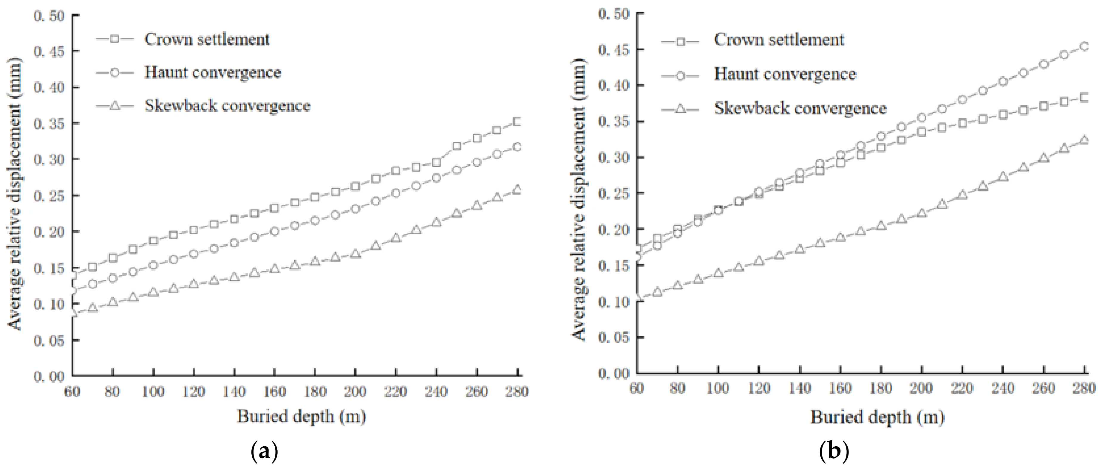
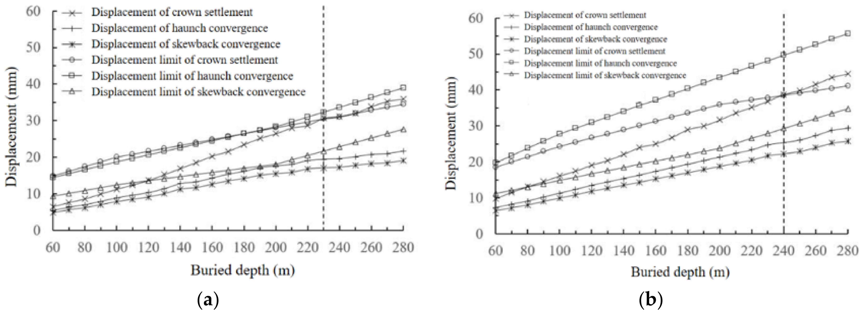
4.1. Determination of Critical Water-Enriched Height
4.2. Analysis of Grouting Results
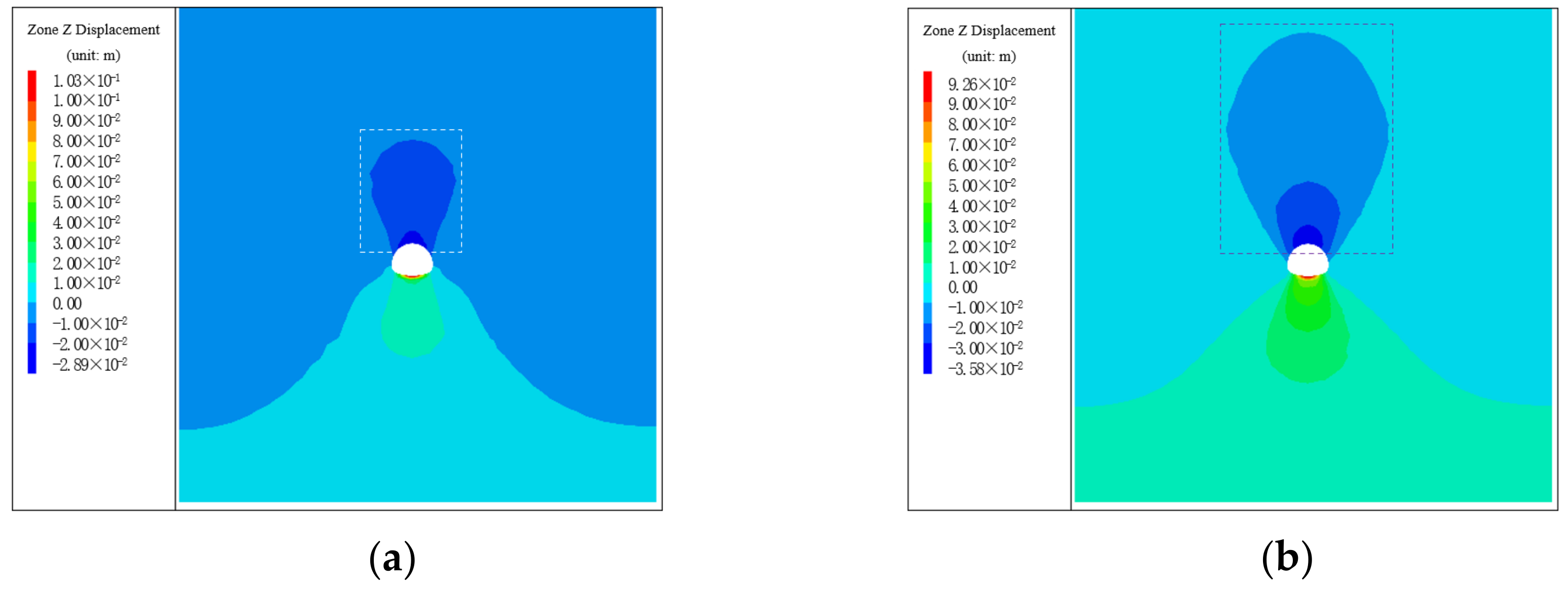
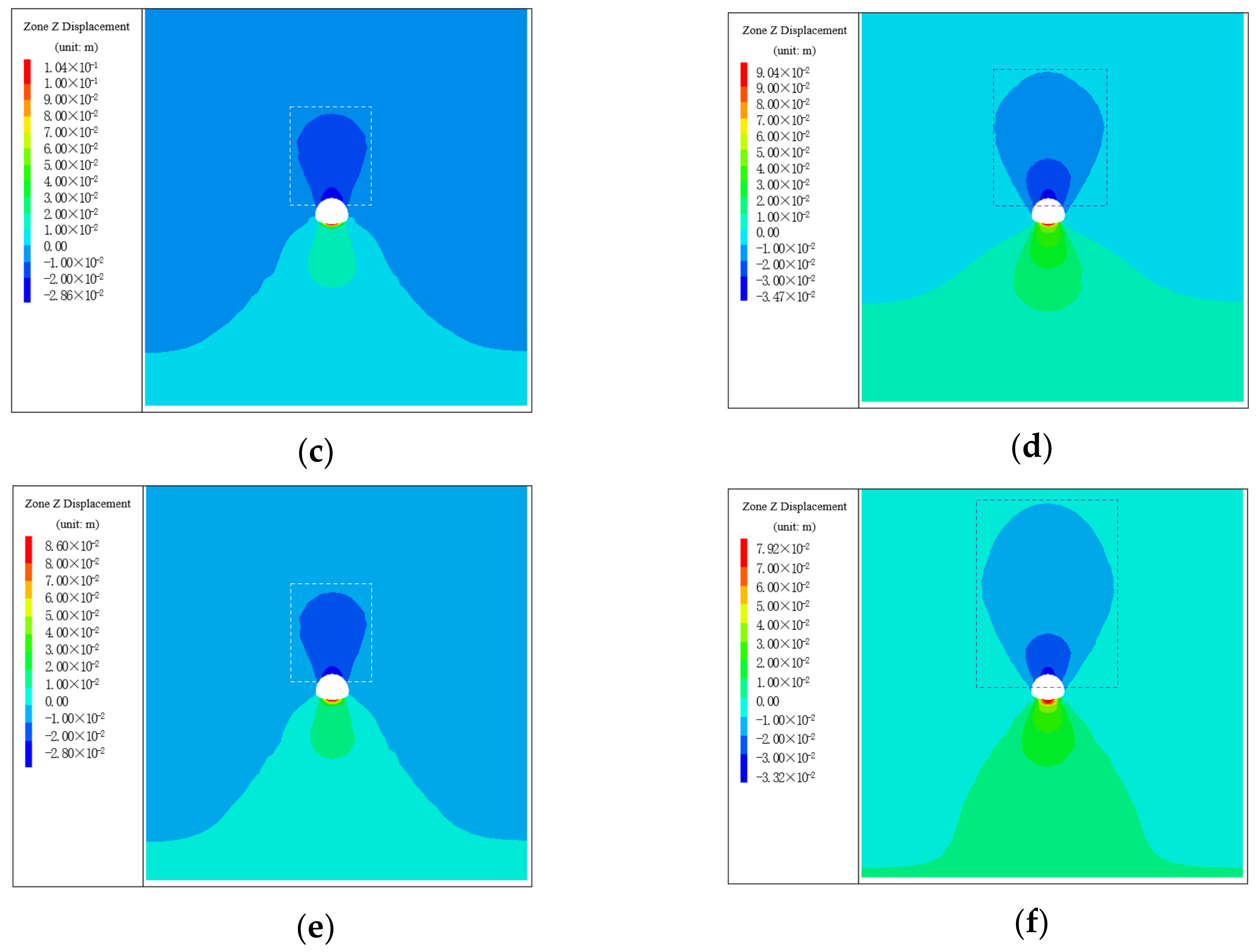
4.2.1. Calculation Results and Analysis of Displacement Field
4.2.2. Calculation Results and Analysis of Seepage Field
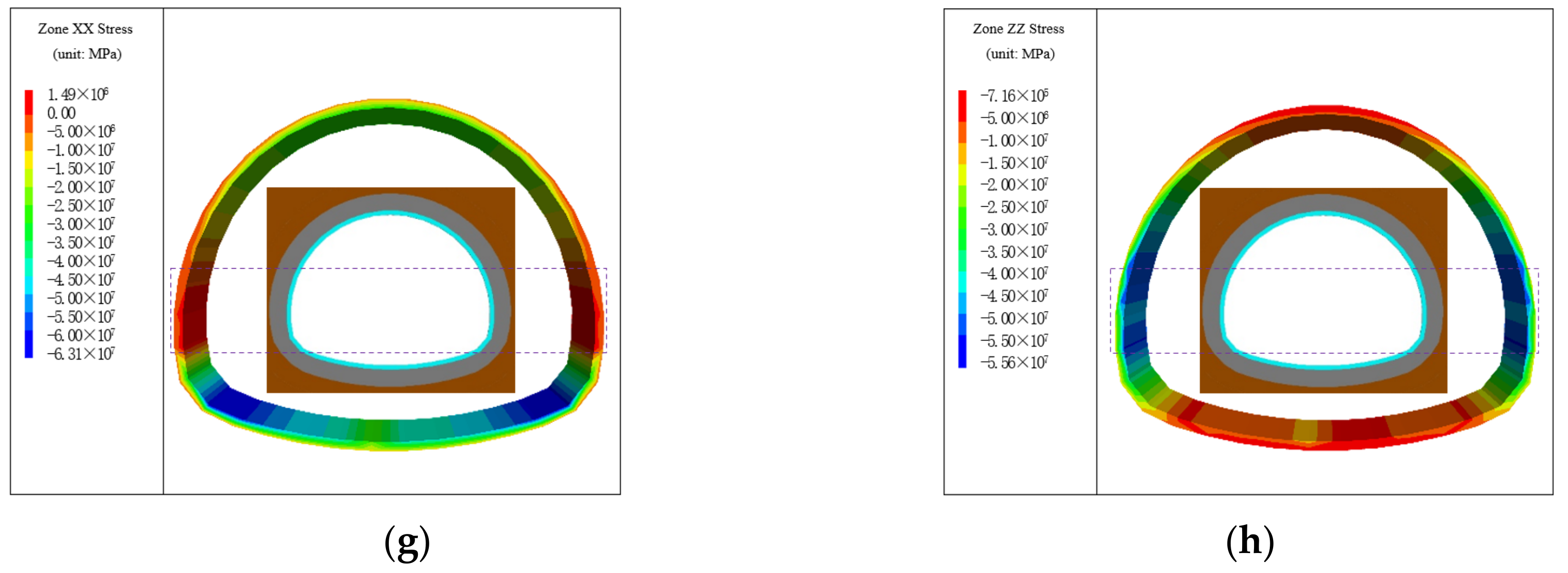
4.2.3. Calculation Results and Analysis of Stress Field
5. Conclusions
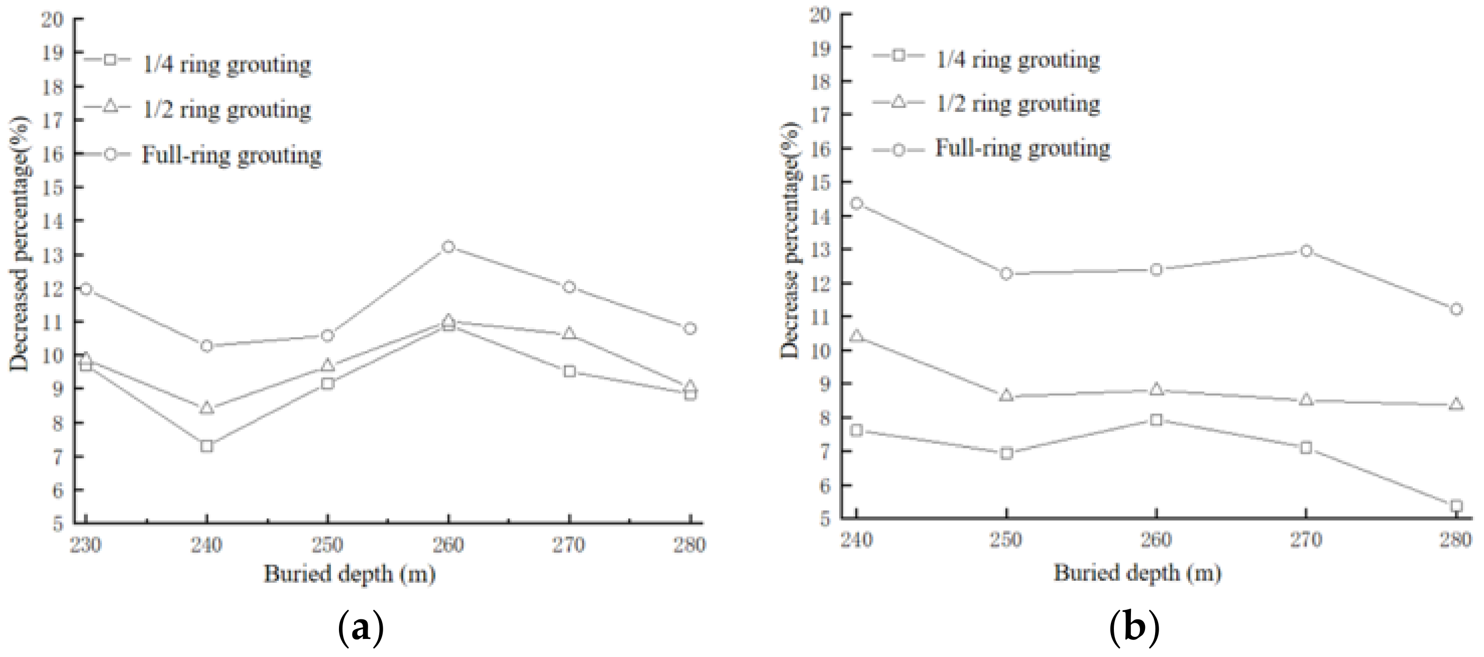
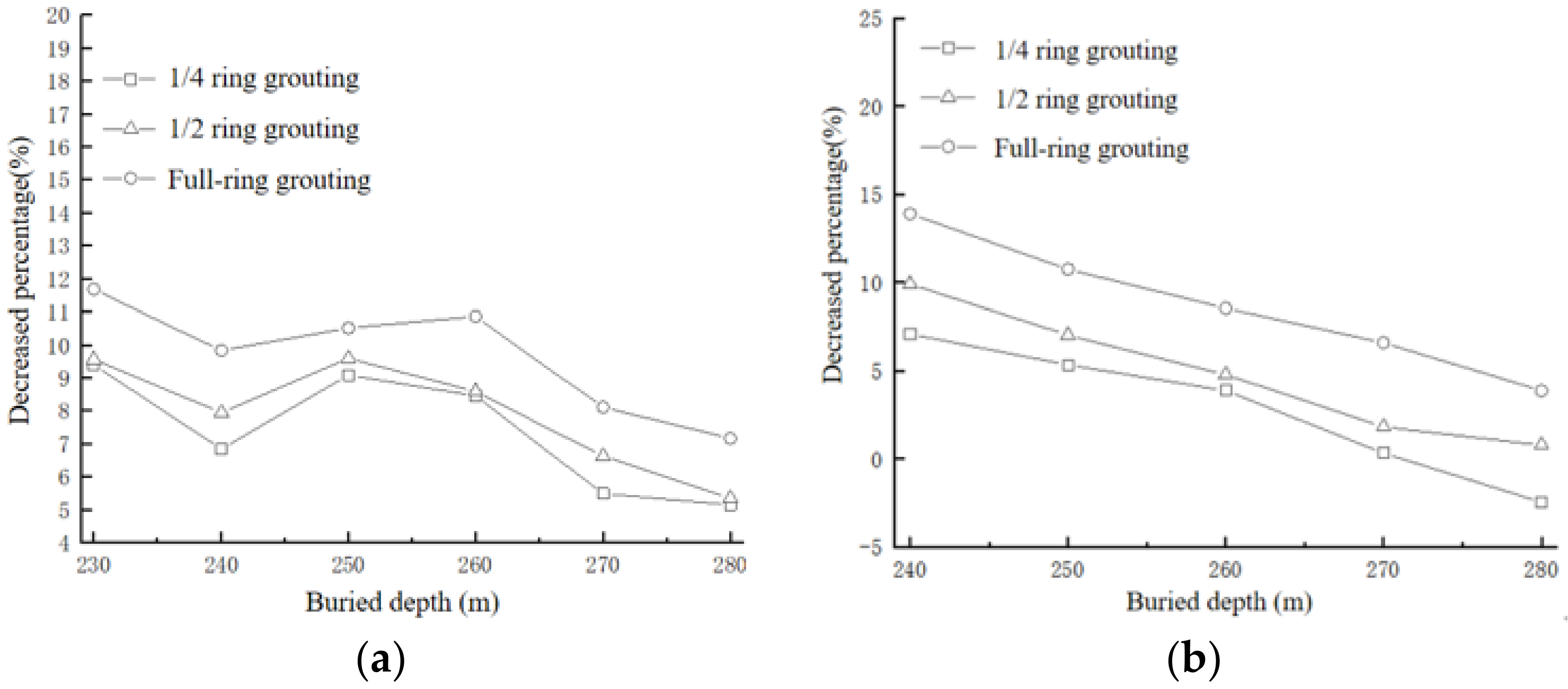
- (1)
- At the same tunnel burial depth, the arch crown settlement displacement decreased with the increase in the circumferential grouting range, which decredses by 5–15%. In the case of Grade V surrounding rock, the groundwater level was 260–270 m higher than the tunnel arch crown. Two schemes can be adopted, namely, 1 m radial grouting reinforcement thickness and 1/2 circumferential grouting reinforcement. When the underground water level was 270–280 m higher than the tunnel arch crown, two schemes could also be adopted, namely, 1 m radial grouting reinforcement thickness and circumferential grouting reinforcement.
- (2)
- The seepage flow without grouting reinforcement, 1/4 circumferential grouting reinforcement, 1/2 circumferential grouting reinforcement, and all circumferential grouting reinforcement was 7 m3/dm, 4 m3/dm, 3 m3/dm, and 0 m3/dm, respectively; with the increase in the reinforcement range of circumferential grouting, the water inflow of the tunnel decreased gradually.
- (3)
- With the enlargement of the circumferential range of the grouting reinforcement ring at the arch crown, the horizontal and vertical stresses of the tunnel initial support gradually decreased, with a smaller range of 10%, and the stress concentration area became smaller and smaller.
Author Contributions
Funding
Data Availability Statement
Conflicts of Interest
References
- Qian, Q.H. Challenges and countermeasures for underground engineering construction safety. J. Rock Mech. Eng. 2012, 31, 1945–1956. [Google Scholar]
- Zhang, Z.E.; Huang, M.L.; Huang, J.F. Discussion on the design of water blocking and drainage limit of water-rich mountain tunnel in ecologically fragile area. IOP Conf. Ser. Earth Environ. Sci. 2020, 510, 052059. [Google Scholar] [CrossRef]
- Wang, H.M.; Pan, G.M.; Liu, C.G.; Zhang, H.S. Research and application of “drainage injection combination” treatment technology for high-pressure water rich tunnels. Mod. Tunn. Technol. 2020, 57, 208–214. [Google Scholar]
- Kolymbas, D.; Wagner, P. Groundwater ingress to tunnels—The exact analytical solution. Tunn. Undergr. Space Technol. 2007, 22, 23–27. [Google Scholar] [CrossRef]
- Hwang, J.H.; Lu, C.-C. A semi-analytical method for analyzing the tunnel water inflow. Tunn. Undergr. Space Technol. 2007, 22, 39–46. [Google Scholar] [CrossRef]
- Zhang, C.; Ali, A.; Sun, L. Investigation on low-cost friction-based isolation systems for masonry building structures: Experimental and numerical studies. Eng. Struct. 2021, 243, 112645. [Google Scholar] [CrossRef]
- Li, R.H.; Gao, X.Q.; Kong, C. Study on the aging deterioration curve of tunnel lining in water rich area. IOP Conf. Ser. Mater. Sci. Eng. 2020, 741, 012021. [Google Scholar] [CrossRef]
- Jeannin, P.Y.; Malard, A.; Rickerl, D.; Weber, E. Assessing karst-hydraulic hazards in tunneling—the Brunnmühle spring system—Bernese Jura, Switzerland. Environ. Earth Sci. 2015, 74, 7655–7670. [Google Scholar] [CrossRef]
- Chen, J.; Tong, H.; Yuan, J.; Fang, Y.; Gu, R. Permeability prediction model modified on Kozeny-Carman for building foundation of clay soil. Buildings 2022, 12, 1798. [Google Scholar] [CrossRef]
- Li, Z.; Chen, Z.-Q.; He, C.; Ma, C.-C.; Duan, C.-R. Seepage field distribution and water inflow laws of tunnels in water-rich regions. J. Mt. Sci. 2022, 19, 591–605. [Google Scholar] [CrossRef]
- Lin, C.; Wang, X.; Nie, L.; Sun, H.; Xu, Z.; Du, Y.; Liu, L. Comprehensive geophysical investigation and analysis of lining leakage for water-rich rock tunnels: A case study of Kaiyuan Tunnel, Jinan, China. Geotech. Geol. Eng. 2020, 38, 3449–3468. [Google Scholar] [CrossRef]
- Shi, H.; Bai, M.; Xing, S. Mechanics parameter optimization and evaluation of curtain grouting material in deep, water-rich karst tunnels. Adv. Mater. Sci. Eng. 2017, 2017, 1853951. [Google Scholar] [CrossRef]
- Zhao, J.P.; Li, J.W.; Bi, L.; Cheng, B.B. Analytical solution of seepage field and reasonable support parameters of tunnel in water rich area. J. Zhejiang Univ. (Eng. Sci.) 2021, 55, 2142–2150. [Google Scholar]
- Fu, H.L.; An, P.T.; Li, K.; Cheng, G.W.; Li, J.; Yu, X.H. Grouting design of rich water tunnels and the calculation of distance between annular blind pipes. Adv. Civ. Eng. 2020, 2020, 8873971. [Google Scholar] [CrossRef]
- Ding, Y.; Zhang, X.; Zhang, B. Preliminary study on double lining support design for water plugging of highway tunnel under high water pressure in mountain area based on limited drainage. Appl. Sci. 2022, 12, 7905. [Google Scholar] [CrossRef]
- Wei, Z.; Zhu, Y. Seepage in water-rich loess tunnel excavating process and grouting control effect. Geofluids 2021, 2021, 5597845. [Google Scholar] [CrossRef]
- Wang, S.; Zhang, H.B.; Ma, S.; Li, J.Q.; Xie, W.B.; Liu, G. Optimization of curtain grouting range for water-rich fault tunnel. IOP Conf. Ser. Earth Environ. Sci. 2021, 859, 012052. [Google Scholar] [CrossRef]
- Jia, Y.L.; Lu, O.Y.; Zhou, S.W.; Wang, G. Study of the thickness of curtain grouting ring for the life-cycle of tunnel in water-rich fault fracture zone. IOP Conf. Ser. Mater. Sci. Eng. 2020, 794, 012018. [Google Scholar] [CrossRef]
- Liu, Y.N.; Yin, W.G.; Zhang, F.Q.; Hu, H.X.; Zhou, H.; Wang, H.B.; Jiang, P. Study on comprehensive treatment method of curtain grouting in water-rich sand layer. IOP Conf. Ser. Earth Environ. Sci. 2018, 189, 022052. [Google Scholar]
- Tian, S.X.; Wang, Y.G. Study on reasonable control parameters of grouting circle in water rich area of Guanjiao Tunnel. Tunn. Constr. 2012, 32, 490–494. [Google Scholar]
- Zou, Y.L.; He, C.; Hu, X.Y.; He, C.; Lan, L.L. Research on reasonable waterproof and drainage types and grouting reinforcement parameters of tunnels in water rich areas. J. Disaster Prev. Reduct. Eng. 2014, 34, 485–491. [Google Scholar]
- Xu, D.Q.; Yan, P.; Li, Y.Q.; Wang, K.Y. Determination of relative displacement value of initial support limit of highway mountain tunnel. Tunn. Constr. 2017, 26, 1083–1088. [Google Scholar]
- Xu, D.Q.; Li, Y.Q.; Yan, P. Limit displacement value of initial support for tunnels with different excavation methods. Ind. Build. 2018, 48, 110–115. [Google Scholar]
- Xu, J.; Lan, W.; Ren, C.; Zhou, X.; Wang, S.; Yuan, J. Modeling of coupled transfer of water, heat and solute in saline loess considering sodium sulfate crystallization. Cold Reg. Sci. Technol. 2021, 189, 103335. [Google Scholar] [CrossRef]
- Fang, B.; Hu, Z.; Shi, T.; Liu, Y.; Wang, X.; Yang, D.; Zhu, K.; Zhao, X.; Zhao, Z. Research progress on the properties and applications of magnesium phosphate cement. Ceram. Int. 2023, 49, 4001–4016. [Google Scholar] [CrossRef]
- Lee, J.; Sagong, M.; Park, J.; Choi, I.Y. Experimental analysis of penetration grouting in umbrella arch method for tunnel reinforcement. Int. J. Rock Mech. Min. Sci. 2020, 130, 104346. [Google Scholar] [CrossRef]
- Kim, J.; Moon, J.S. Change of groundwater inflow by cutoff grouting thickness and permeability coefficient. Geomech. Eng. 2020, 21, 165–170. [Google Scholar]
- Li, M.; Zhang, X.; Kuang, W.; Zhou, Z. Grouting reinforcement of shallow and small clearance tunnel. Pol. J. Environ. Stud. 2021, 30, 2609–2620. [Google Scholar] [CrossRef]
- Zhang, Z.; Liang, G.; Niu, Q.; Wang, F.; Chen, J.; Zhao, B.; Ke, L. A Wiener degradation process with drift-based approach of determining target reliability index of concrete structures. Qual. Reliab. Eng. Int. 2022, 38, 3710–3725. [Google Scholar] [CrossRef]
- Qi, Y.; Wei, G.; Xie, Y.; Wang, Q. Effect of grouting reinforcement on settlement of existing tunnels: Case study of a new crossing underpass. Symmetry 2021, 13, 482. [Google Scholar] [CrossRef]
- Fransson, A.; Gustafson, G. The use of transmissivity data from probe holes for predicting tunnel grouting—Analyses of data from the access tunnel to the Aspo Hard Rock Laboratory. Tunn. Undergr. Space Technol. Inc. Trenchless Technol. Res. 2000, 15, 365–368. [Google Scholar] [CrossRef]
- Aggelis, D.G.; Shiotani, T.; Kasai, K. Evaluation of grouting in tunnel lining using impact-echo. Tunn. Undergr. Space Technol. 2008, 23, 629–637. [Google Scholar] [CrossRef] [Green Version]
- Shin, Y.-J.; Song, K.I.; Lee, I.-M.; Chod, G.-C. Interaction between tunnel supports and ground convergence—Consideration of seepage forces. Int. J. Rock Mech. Min. Sci. 2011, 48, 394–405. [Google Scholar] [CrossRef]
- Fu, Q.; Gu, M.; Yuan, J.; Lin, Y. Experimental study on vibration velocity of piled raft supported embankment and foundation for ballastless high speed railway. Buildings 2022, 12, 1982. [Google Scholar] [CrossRef]
- Ren, C.; Yu, J.; Liu, S.; Yao, W.; Zhu, Y.; Liu, X. A plastic strain-induced damage model of porous rock suitable for different stress paths. Rock Mech. Rock Eng. 2022, 55, 1887–1906. [Google Scholar] [CrossRef]
- Yu, J.; Zhu, Y.; Yao, W.; Liu, X.; Ren, C.; Cai, Y.; Tang, X. Stress relaxation behaviour of marble under cyclic weak disturbance and confining pressures. Measurement 2021, 182, 109777. [Google Scholar] [CrossRef]
- Lisa, H.; Christian, B.; Asa, F.; Gunnar, G.; Johan, F. A hard rock tunnel case study: Characterization of the water-bearing fracture system for tunnel grouting. Tunn. Undergr. Space Technol. Inc. Trenchless Technol. Res. 2012, 30, 132–144. [Google Scholar] [CrossRef]
- Bohloli, B.; Skjolsvold, O.; Justnes, H.; Olsson, R.; Grov, E.; Aarset, A. Cements for tunnel grouting—Rheology and flow properties tested at different temperatures. Tunn. Undergr. Space Technol. 2019, 91, 103011. [Google Scholar] [CrossRef]


| Material | Parameter | ||||||
|---|---|---|---|---|---|---|---|
| Modulus of Elasticity E (GPa) | Poisson’s Ratio μ | Unit Weight γ (kN/m3) | Internal Friction Angle φ (°) | Cohesive Force c (MPa) | Permeability Coefficient K (m2/Pa-s) | Porosity n | |
| Grade IV surrounding rock | 3.90 | 0.30 | 22 | 37 | 0.6 | 3.25 × 10⁻⁸ | 0.323 |
| Grade V surrounding rock | 1.40 | 0.36 | 19 | 24 | 0.13 | 3.85 × 10⁻⁸ | 0.363 |
| Primary support | 21.26 | 0.17 | 24 | - | - | 5.0 × 10⁻¹³ | 0.090 |
| Grouting ring | 16.8 | 0.21 | 20 | 45 | 0.9 | 5.0 × 10⁻¹³ | 0.100 |
| Surrounding Rock Grade | Distance from the Groundwater Level to the Crown (m) | Grouting Scheme |
|---|---|---|
| Grade IV surrounding rock | 230–280 | 1 m thick grouting and 1/4 ring grouting |
| Grade V surrounding rock | 240–260 | 1 m thick grouting and 1/4 ring grouting |
| Grade V surrounding rock | 260–270 | 1 m thick grouting and 1/2 ring grouting |
| Grade V surrounding rock | 270–280 | 1 m thick grouting and full-ring grouting |
Disclaimer/Publisher’s Note: The statements, opinions and data contained in all publications are solely those of the individual author(s) and contributor(s) and not of MDPI and/or the editor(s). MDPI and/or the editor(s) disclaim responsibility for any injury to people or property resulting from any ideas, methods, instructions or products referred to in the content. |
© 2023 by the authors. Licensee MDPI, Basel, Switzerland. This article is an open access article distributed under the terms and conditions of the Creative Commons Attribution (CC BY) license (https://creativecommons.org/licenses/by/4.0/).
Share and Cite
Hua, T.; Liu, S.; Zhang, X.; Meng, L.; Wang, P. Numerical Analysis of Grouting of Water-Enriched Karst Highway Tunnel Based on Critical Water-Enriched Height. Processes 2023, 11, 149. https://doi.org/10.3390/pr11010149
Hua T, Liu S, Zhang X, Meng L, Wang P. Numerical Analysis of Grouting of Water-Enriched Karst Highway Tunnel Based on Critical Water-Enriched Height. Processes. 2023; 11(1):149. https://doi.org/10.3390/pr11010149
Chicago/Turabian StyleHua, Tao, Shiyang Liu, Xuefu Zhang, Lianghua Meng, and Pan Wang. 2023. "Numerical Analysis of Grouting of Water-Enriched Karst Highway Tunnel Based on Critical Water-Enriched Height" Processes 11, no. 1: 149. https://doi.org/10.3390/pr11010149