Article

Influence of the Machining Process on the Thrust Force and Mechanical Characteristics for the Direct Drive System

1
School of Aeronautics, Northwestern Polytechnical University, Xi’an 710072, China
2
State Key Laboratory for Manufacturing Systems Engineering, Xi’an Jiaotong University, Xi’an 710054, China
*
Author to whom correspondence should be addressed.
Processes 2023, 11(1), 17; https://doi.org/10.3390/pr11010017
Submission received: 25 November 2022 / Revised: 16 December 2022 / Accepted: 20 December 2022 / Published: 22 December 2022
(This article belongs to the Special Issue High-Performance Machining Processes: From Mechanisms to Equipment)

Abstract

:
This paper investigates the effects of the machining process on the thrust force and mechanical characteristics for the direct drive feed system driven by the flat permanent magnet synchronous linear motor (PMSLM) in machine tools considering the electromechanical couplings. Firstly, the cutting force in the machining process is researched. Then, the analytical model of the direct drive feed system is established and analyzed. The electromechanical couplings between the mechanical system and servo system in the direct drive feed system are studied. Furthermore, the influences of the cutting force on different couplings are analyzed, and the thrust force characteristic is analytically represented. Finally, the validity of the theoretical analysis is verified by the experiments, and the effects of the machining process on the dynamic precision of the feed system are discussed. The results show that the electromechanical couplings in the direct drive system will aggravate the effects of the machining process on the thrust force and mechanical characteristics of the feed system. A large number of new paired thrust harmonics will be produced. The influence of the machining process on the mechanical system will be extended from the discrete frequency point caused by the cutting force to the approximate frequency band caused by the thrust force, affecting the dynamic precision of the feed system and the cutting stability of the machine tool.

1. Introduction

The direct drive feed system incorporates the merits of simple structure, fast response, high velocity, and high acceleration, which has a bright future in railway transportation, robotic systems, micro aerial vehicle, electromagnetic launchers, and machine tools [1,2].
Due to the non-linearity of the drive circuit and the motor structure, there are lots of harmonics in the thrust force. The thrust fluctuation is one of the significant restrictions for the direct-driven feed system, which has been concerned and studied by scholars. Different kinds of structure optimization and compensation methods have been proposed [3,4,5,6,7,8,9,10], which have important significance for reducing the thrust fluctuation and improving the performance of the feed system. Although the direct drive feed system has outstanding performance advantages, its application is still far less than the traditional lead screw until now in the high-speed machine tool. There are obvious thrust harmonics and displacement fluctuations, especially in the machining process. In order to improve the machining accuracy, much research about the modeling of the cutting force and the optimization of the machining parameters has been conducted [11,12,13,14,15]. The influence of the machining process on the mechanical system is mainly concerned with the mechanical vibration caused by the cutting force itself under different cutting parameters and cutting stability. The dynamic precision of the feed system has an important influence on the final surface quality and the dimensional accuracy of parts [16]. The integrated modeling and optimization design method have been produced for the ball screw feed system in machine tools considering the machining process [17,18]. However, the coupling between the servo system and the mechanical system has not been paid enough attention in the current research. The dynamic characteristics of the mechanical system are ignored for the direct drive feed system. Although many scholars have paid attention to the electromechanical coupling problem in the direct drive feed system [19,20,21], the influence of the machining process has not been considered. In the machining process, there are many more disturbances caused by various non-ideal factors, such as cutting force, cooling pump, complex mechanical vibrations, and so on. The disturbances may aggravate the electromechanical couplings in the direct drive system, putting forward higher requirements for the dynamic precision and the control system of the feed system.
Therefore, in this paper, the effects of the machining process on the thrust force and mechanical characteristics are investigated for the direct drive feed system in machine tools considering the dynamic electromechanical couplings. Firstly, the cutting force in the milling process and the dynamic characteristic of the direct drive system are analyzed, respectively. Then the electromechanical couplings between the mechanical system and servo system in the direct drive feed system are studied. Furthermore, the influences of the cutting force on different couplings are analyzed, and the thrust force characteristic is analytically represented. Finally, the validity of the previous theoretical analysis is verified by the experiments, and the effects of the machining process on the dynamic precision of the feed system are discussed.

2. Analysis of the Cutting Force and the Dynamic Characteristics of the Direct Drive System

2.1. Analysis of the Cutting Force in the Milling Process

The milling is a discontinuous cutting process involving multiple teeth. The cutting force is ever-changing in the milling process. In order to improve the machining accuracy, it is necessary to predict the milling force for improving the tool life and maintaining the stability of machining quality. Furthermore, an accurate force model is also the basis for optimizing milling parameters and maintaining process stability. Considerable research has been conducted to build a reliable cutting force prediction model [22,23,24]. This paper mainly focuses on the influence of cutting force on the direct drive feed system. Therefore, the cutting force itself is not further studied. Based on the previous research, in the milling process, the cutting force can be expressed as:
{ F c x ( t ) = j = 1 F c x j sin ( ω c x j t + ϕ c x j ) F c y ( t ) = j = 1 F c y j sin ( ω c y j t + ϕ c y j ) F c z ( t ) = j = 1 F c z j sin ( ω c z j t + ϕ c z j )
It can be seen from Equation (1) there are lots of harmonics in the cutting force with different frequencies which are related to the machining parameters.

2.2. Analysis of Dynamic Characteristic of the Direct Drive System

The analytical model of the direct drive feed system is established as shown in Figure 1. The drive circuit is consisting of modulator circuit, rectifier, filter circuit and inverter. In order to produce the ideal thrust force, the three phase currents are expected to be ideal sine waveforms. However, there are different kinds of the nonlinear factors in the drive circuit (such as dead time effect, error of the sensor, back electromotive force), leading to lots of harmonics.
The three phase windings of PMSLM are a star connection without the mid-line, which does not contain three times harmonics. Ignoring the transient response and setting the initial phase equal to zero, the servo current can be obtained as:
{ i a ( t ) = m = 1 , 5 , 7 , , 6 i ± 1 I a m sin [ m ( π v τ t + θ ) ] i b ( t ) = m = 1 , 5 , 7 , , 6 i ± 1 I b m sin [ m ( π v τ t + θ 2 π / 3 ) ] i b ( t ) = m = 1 , 5 , 7 , , 6 i ± 1 I c m sin [ m ( π v τ t + θ 4 π / 3 ) ]
In Figure 1, x0o0z0 and xoz are the coordinate system of the mover and the stator, respectively. x represents the position of the mover in the coordinate system of the stator. Based on the Maxwell’s equations, the magnetic field distributions in air-gap are calculated and given by:
B m ( x , z ) = 4 B r π n = 1 , 3 , 5 { ( 1 ) n + 3 2 n sin n π w p 2 τ s h ( n π τ h ) s h [ n π τ ( h + g ) ] c h [ n π τ ( h + g z ) ] cos ( n π τ z ) }
The SC transformation is introduced to analyze the detent force. Based on the analysis in [25,26], the magnetic field distributions in air-gap considering the slotting effect and end effect can be obtained as:
B m a ( x , z ) = B m ( x , z ) λ s ( x , z ) λ e ( x , z )
where, λs(x,z) and λe(x,z) represent the relative permeance function considering the slotting effect and end effect, respectively.
The thrust force of PMSLM can be calculated as follows using the electromagnetic energy method.
F m ( t ) = 1 v { t [ ( L a + M a b + M a c ) i a ( t ) ] N l t [ x τ / 2 x + τ / 2 B a ( x ) d x ] } i a ( t ) + 1 v { t [ ( L b + M a b + M b c ) i b ( t ) ] N l t [ x τ / 2 x + τ / 2 B b ( x ) d x ] } i b ( t ) + 1 v { t [ ( L c + M b c + M a c ) i c ( t ) ] N l t [ x τ / 2 x + τ / 2 B c ( x ) d x ] } i c ( t )
Ignoring the harmonic components of the self-inductance and mutual inductance in the coil, substituting Equations (2) and (4) into Equation (5), the thrust force can be obtained as:
F m ( t ) = F 0 ( t ) + F m r ( t ) = F 0 ( t ) + i F m i ( t )
The mechanical structure of the direct drive feed system consists of worktable, linear guide, motor mover, permanent magnet, linear encoder and machine bed. The flexibility of the worktable and the machine bed is ignored. The mechanical vibrations of the worktable can be assumed as the linear displacements along three axis x, y, and z, and the angle displacements around three axes, θx, θy and θz, respectively. Considering the cutting force, the dynamic equation of the mechanical system can be obtained as follows.
M X ¨ + C X ˙ + K X = H c F c + H m F m r
where, X = [ x y z θ x θ y θ z ] T , M, C, K are mass matrix, damping matrix and stiffness matrix, respectively.
H m = [ H x m H y m H z m H θ x H θ y H θ z ] T ,   H c = [ H x c 0 0 0 H y c 0 0 0 H z c 0 H x y c H x z c H y x c 0 H y z c H z x c H z y c 0 ] ,   F c = [ F c x F c y F c z ] .
In order to facilitate subsequent calculations, the coupling between each modal and higher-order modes of mechanical vibrations is ignored. The stiffness and damping in the vertical and tangential directions are large, leading to tiny amplitudes of the vibrations [27]. The main vibration responses in different directions can be obtained as:
X = [ x θ x θ y θ z ] = [ x m + x c θ m x + θ c x θ m y + θ c y θ m z + θ c z ] = [ i x m i sin ( ω x m i t + φ x m i ) + i x c i sin ( ω x c i t + φ x c i ) i θ m x i sin ( ω θ m x i t + φ θ m x i ) + i θ c x i sin ( ω θ c x i t + φ θ c x i ) i θ m y i sin ( ω θ m y i t + φ θ m y i ) + i θ c y i sin ( ω θ c y i t + φ θ c y i ) i θ m z i sin ( ω θ m z i t + φ θ m z i ) + i θ c z i sin ( ω θ c z i t + φ θ c z i ) ]
It can be obtained from Equation (8) that there are complex multi-frequency mechanical vibrations in the direct drive feed system considering the excitation of the thrust force and cutting force.

3. Analysis of the Dynamic Electromechanical Couplings in the Direct Drive System Considering the Cutting Force

In the direct drive feed system, the mover of PMSLM is directly connected with the mechanical system. The couplings between the servo system and mechanical system become more complex and prominent. Multiple coupling loops, which are overlapped and influenced by each other, determine the dynamic precision of the feed system. The coupling condition and influence factor of each coupling are different. However, in electromechanical couplings, the intermediate coupling parameters all are motor thrust harmonics [21]. In the machining process, the cutting force harmonics with multiple frequencies act on the mechanical system of the direct drive feed system, which will affect the electromechanical couplings as shown in Figure 2. Therefore, in this section, the effects of the cutting force on the thrust force are mainly analyzed considering different kinds of couplings.

3.1. Effects of the Cutting Force on the Thrust Force Considering the Air-Gap Fluctuation

In the direct drive feed system, the mechanical vibration in the normal direction of the worktable will produce the mover eccentricity, leading to air-gap fluctuation. Especially in the machining process, the torsional vibration of the mechanical system will be aggravated by the cutting forces in three directions.
Considering the mechanical pitch and roll vibrations, the relative permeance functions between actual and ideal air-gap are introduced to represent the effects of the air-gap fluctuations on the magnetic field distributions in the air-gap.
In the roll vibration, the high order terms are ignored in three coefficients, and the whole relative permeability function caused by the air-gap fluctuation can be calculated as shown in Equation (9).
λ r ( t ) = L m b + L m b 6 ( L m b 2 g ) 2 A r 2 L m b 6 ( L m b 2 g ) 2 A r 2 cos ( 2 ω r 0 t )
In the pitch vibration, the relative permeance function between actual and ideal air-gap is equal to
λ p ( x 0 , t ) = a 0 + i = 1 [ a i cos ( 2 i π L x 0 ) + b i sin ( 2 i π L x 0 ) ]
where, a 0 = 1 + 1 6 ( L a A p 2 g ) 2 1 6 ( L a A p 2 g ) 2 cos ( 2 ω p 0 t ) , a i = 3 ( L a A p 2 i π g ) 3 sin ( ω p 0 t ) ( L a A p 2 i π g ) 3 sin ( 3 ω p 0 t ) , b i = ( L a A p 2 i π g ) 2 + ( L a A p 2 i π g ) 2 cos ( 2 ω p 0 t ) .
In order to simplify the calculation process, the slotting effect and end effect are ignored. Using the Equations (4), (9) and (10), the magnetic field distributions considering the air-gap fluctuation can be obtained as:
B ( x + x 0 , z ) = λ r ( x 0 , t ) λ p ( x 0 , t ) B m a ( x , z )
Substituting Equations (2) and (11) into Equation (5), the thrust force can be given by
F c a g = F 0 ( t ) + F r ( t ) + F c r ( t ) + F c p ( t ) + F c r p ( t )
where, F 0 ( t ) represents the new nominal thrust force, and
F 0 ( t ) = { [ L b + L b 6 ( L b 2 g ) 2 A r 2 ] [ 1 + 1 6 ( L a A p 2 g ) 2 ] [ τ n π sin ( n L a π 2 τ ) ] + i = 1 , 2 , 3 [ L b + L b 6 ( L b 2 g ) 2 A r 2 ] ( L a A p 2 i π g ) 2 [ 4 i L a τ 2 π ( 1 ) i B n ( 2 i π τ ) 2 ( n L a π ) 2 sin ( n L a π 2 τ ) ] } F 0 ( t )
F r ( t ) represents the original thrust harmonics, and
F r ( t ) = n , m , j { [ L b + L b 6 ( L b 2 g ) 2 A r 2 ] [ 1 + 1 6 ( L a A p 2 g ) 2 ] [ τ n π sin ( n L a π 2 τ ) ] + i = 1 , 2 , 3 , [ L b + L b 6 ( L b 2 g ) 2 A r 2 ] ( L a A p 2 i π g ) 2 [ 4 i L a τ 2 π ( 1 ) i ( 2 i π τ ) 2 ( n L a π ) 2 B n sin ( n L a π 2 τ ) ] } F r n cos ( 6 j ω 0 t )
Fcr(t) represents the new thrust harmonics caused by the roll vibrations, and
F c r ( t ) = n , m , j { [ L b + L b 6 ( L b 2 g ) 2 A r 2 ] [ 1 + 1 6 ( L a A p 2 g ) 2 ] [ τ n π sin ( n L a π 2 τ ) ] + i = 1 , 2 , 3 [ L b + L b 6 ( L b 2 g ) 2 A r 2 ] ( L a A p 2 i π g ) 2 [ 4 i L a τ 2 π ( 2 i π τ ) 2 ( n L a π ) 2 ( 1 ) i B n sin ( n L a π 2 τ ) ] } · [ F r n cos ( 6 j ω 0 t + 2 ω r 0 t ) + F r n cos ( 6 j ω 0 t 2 ω r 0 t ) ]
Fcp(t) represents the new thrust harmonics caused by the pitch vibrations, and
F c p ( t ) = F c p 1 ( t ) + F c p 2 ( t ) + F c p 3 ( t )
F c p 1 ( t ) = n , m , j F c p i = 1 , 2 , 3 { [ L b + L b 6 ( L b 2 g ) 2 A r 2 ] [ 3 ( L a A p 2 i π g ) 3 ] [ 2 n L a 2 τ π ( 1 ) i B n ( 2 i π τ ) 2 ( n L a π ) 2 sin ( n L a π 2 τ ) ] } [ sin ( 6 j ω 0 t + ω p 0 t ) + sin ( 6 j ω 0 t ω p 0 t ) ]
F c p 2 ( t ) = n , m , j { [ L b + L b 6 ( L b 2 g ) 2 A r 2 ] [ 1 6 ( L a A p 2 g ) 2 ] [ B n τ n π sin ( n L a π 2 τ ) ] + i = 1 , 2 , 3 { [ L b + L b 6 ( L b 2 g ) 2 A r 2 ] ( L a A p 2 i π g ) 2 [ 4 i L a τ 2 π ( 2 i π τ ) 2 ( n L a π ) 2 ( 1 ) i B n sin ( n L a π 2 τ ) ] } } · [ F c p cos ( 6 j ω 0 t + 2 ω p 0 t ) + F c p cos ( 6 j ω 0 t 2 ω p 0 t ) ]
F c p 3 ( t ) = n , m , j F c p i = 1 , 2 , 3 { [ L b + L b 6 ( L b 2 g ) 2 A r 2 ] [ ( L a A p 2 i π g ) 3 ] [ 2 n L a 2 τ π ( 1 ) i B n ( 2 i π τ ) 2 ( n L a π ) 2 sin ( n L a π 2 τ ) ] } [ sin ( 6 j ω 0 t + 3 ω p 0 t ) + sin ( 6 j ω 0 t 3 ω p 0 t ) ]
Fcrp(t) represents the new thrust harmonics caused by the couplings between the roll and pitch, and
F c r p ( t ) = F c r p 1 ( t ) + F c r p 2 ( t ) + F c r p 3 ( t )
F c r p 1 ( t ) = n , m , j F c r p i = 1 , 2 , 3 { [ L b 6 ( L b 2 g ) 2 A r 2 ] 3 ( L a A p 2 i π g ) 3 [ 2 n L a 2 τ π ( 1 ) i ( 2 i π τ ) 2 ( n L a π ) 2 B n sin ( n L a π 2 τ ) ] } [ sin ( 2 ω r 0 t + ω p 0 t + 6 j ω 0 t ) + sin ( 2 ω r 0 t + ω p 0 t 6 j ω 0 t ) + sin ( 2 ω r 0 t ω p 0 t + 6 j ω 0 t + π ) + sin ( 2 ω r 0 t ω p 0 t 6 j ω 0 t + π ) ]
F c r p 2 ( t ) = n , m , j { [ L b 6 ( L b 2 g ) 2 A r 2 ] [ 1 6 ( L a A p 2 g ) 2 ] [ B n τ n π sin ( n L a π 2 τ ) ] + i = 1 , 2 , 3 { [ L b 6 ( L b 2 g ) 2 A r 2 ] ( L a A p 2 i π g ) 2 [ 4 i L a τ 2 π ( 1 ) i ( 2 i π τ ) 2 ( n L a π ) 2 ( 1 ) i B n sin ( n L a π 2 τ ) ] } } [ F c r p cos ( 2 ω r 0 t + 2 ω p 0 t + 6 j ω 0 t ) + F c r p cos ( 2 ω r 0 t + 2 ω p 0 t 6 j ω 0 t ) + F c r p cos ( 2 ω r 0 t 2 ω p 0 t + 6 j ω 0 t ) + F c r p cos ( 2 ω r 0 t 2 ω p 0 t 6 j ω 0 t ) ]
F c r p 3 ( t ) = n , m , j F c r p i = 1 , 2 , 3 { [ L b 6 ( L b 2 g ) 2 A r 2 ] ( L a A p 2 i π g ) 3 [ 2 n L a 2 τ π ( 2 i π τ ) 2 ( n L a π ) 2 ( 1 ) i B n sin ( n L a π 2 τ ) ] } [ sin ( 2 ω r 0 t + 3 ω p 0 t + 6 j ω 0 t ) + sin ( 2 ω r 0 t + 3 ω p 0 t 6 j ω 0 t ) + sin ( 2 ω r 0 t 3 ω p 0 t + 6 j ω 0 t + π ) + sin ( 2 ω r 0 t 3 ω p 0 t 6 j ω 0 t + π ) ]
F r n = 12 N l B r π 1 n sin n π w p 2 τ sh ( n π τ h ) sh [ n π τ ( h + g ) ] ch ( n π h s 2 τ ) I m sin ( n π 2 ) ,   F c r p = 0.75 N l I m sin ( n π 2 )
B n = 4 B r π 1 n sin n π w p 2 τ sh ( n π τ h ) sh [ n π τ ( h + g ) ] ch ( n π h s 2 τ ) ,   F c p = 1.5 N l I m sin ( n π 2 )
It can be obtained from Equation (12) that the air-gap fluctuation will produce lots of new unbalanced magnetic thrust harmonics. Meanwhile, there is complex coupling between the effects of the roll and pitch vibrations, leading to more new coupled thrust harmonics. The frequencies of these new coupled harmonics are related to the frequencies of the original thrust force harmonics and these of the mechanical torsional vibrations. The amplitudes of these new unbalanced magnetic thrust harmonics depend on the structure parameters of PMSLM and amplitudes of the mechanical vibrations. Only the ripple thrust harmonics are considered in previous calculation. The slot effect and end effect will produce more new coupling thrust harmonics. Their influences on motor thrust can be obtained by using a calculation method similar to the ripple thrust, which ismethods not discussed here.

3.2. Effects of the Cutting Force on the Thrust Force Considering the Feedback Control

In the direct drive feed system, the linear encoder, which is mounted on the worktable, is generally adopted to realize the full-closed loop control. In the machining process, the mechanical vibrations in the feed direction caused by the cutting force and other disturbances will be collected by the reading head of the encoder to produce the feedback harmonics. The feedback harmonics will produce the regulating thrust force to suppress the disturbances through the servo control system. However, because of the non-linearity of the drive circuit and PMSLM, the feedback control will intensify the coupling between the different harmonics, affecting the thrust force characteristics.
In order to reduce the calculation process, the motion error caused by one of the cutting force harmonics is considered here, and the feedback error is assumed to be
x c e ( t ) = x c e 0 cos ( 2 π f c 0 t + α c e 0 )
The three-phase current of the drive circuit can be calculated as follows considering the feedback harmonics.
{ i a ( t ) = m I a m sin [ m ( π v τ t + θ ) ] + i q c e 0 cos ( 2 π f c 0 t + γ c e 0 ) sin ( ω t )           i b ( t ) = m I b m sin [ m ( π v τ t + θ 2 π / 3 ) ] + i q c e 0 cos ( 2 π f c 0 t + γ c e 0 ) sin ( ω t 2 π / 3 ) i b ( t ) = m I c m sin [ m ( π v τ t + θ 4 π / 3 ) ] + i q c e 0 cos ( 2 π f c 0 t + γ c e 0 ) sin ( ω t 4 π / 3 )
Substituting Equations (4) and (14) into Equation (5), the thrust force can be obtained as:
F m f ( t ) = F 0 ( t ) + F m r ( t ) + F c e ( t )
where, F0(t) represents the nominal thrust force, Fmr(t) represents the original thrust harmonics, and Fce(t) represents the new thrust harmonics caused by the feedback harmonics, F c e ( t ) = F c e 0 ( t ) + F c e r ( t ) + F c e s ( t ) + F c e r s ( t ) .
Fce0(t) represents the nominal regulating thrust force caused by the feedback harmonics, and F c e 0 ( t ) = a 0 F c 0 cos ( 2 π f c 0 t + η c e 0 ) .
Fcer(t) represents the new thrust harmonics caused by the couplings between the feedback harmonics and ripple thrust, and
F c e r ( t ) = n + 1 = 6 j   o r   n 1 = 6 j n = 1 , 3 , 5 , j = 1 , 2 , 3 , 1.5 N l a 0 B n I q r 0 sin ( n π 2 ) { cos [ ( 6 j π v τ + 2 π f c 0 ) t + η c e 0 ] + cos [ ( 6 j π v τ 2 π f c 0 ) t η c e 0 ] }
Fces(t) represents the new thrust harmonics caused by the couplings between the feedback harmonics and slot force, and
F c e s ( t ) = i = 1 0.75 N l a i B 1 I q r 0 cos ( i τ π τ s ) [ cos ( 2 π f c 0 t + 2 i π v τ s t + η c e 0 ) + cos ( 2 π f c 0 t 2 i π v τ s t + η c e 0 ) ]
Fcers(t) represents the new thrust harmonics caused by the couplings, and
F c e r s ( t ) = n + 1 = 6 j   o r   n 1 = 6 j n = 1 , 3 , 5 , j = 1 , 2 , 3 , i = 1 0.75 N l a i B n I q r 0 sin ( n π 2 ) cos ( i τ π τ s ) { cos [ ( 6 j π v τ + 2 i π v τ s + 2 π f c 0 ) t + η c e 0 ] + cos [ ( 6 j π v τ + 2 i π v τ s 2 π f c 0 ) t η c e 0 ] + cos [ ( 6 j π v τ 2 i π v τ s + 2 π f c 0 ) t + η c e 0 ] + cos [ ( 6 j π v τ 2 i π v τ s 2 π f c 0 ) t η r 0 ] }
a 0 = 1 K c [ 1 1.6 w s τ s β c ] ,   a i = 4 i π β c [ 0.5 + ( w s τ s i ) 2 0.78215 2 ( w s τ s i ) 2 ] sin ( 1.6 π w s τ s i )
It can be obtained from Equation (15) that the couplings between the feedback harmonics and the non-linearity of the drive circuit and PMSLM will produce a great number of the coupled thrust harmonics.
In addition, the mechanical vibrations may change the optical path between the reading head mounted on the worktable and the scale mounted on the machine bed, leading to encoder errors. Based on the results in Ref. [28], the different kinds of encoder errors caused by the mechanical vibrations in the machining process can be represented as:
{ Δ δ y e = A Δ δ y sin ( ω Δ δ y t + ϕ Δ δ y ) Δ δ r e = Δ δ r 0 + A Δ δ r cos ( ω Δ δ r t + ϕ Δ δ r )   Δ δ p e = Δ δ p 0 + A Δ δ p cos ( ω Δ δ p t + ϕ Δ δ p )
The three-phase servo currents considering encoder errors can be given by
{ i a ( t ) = [ i q Δ δ r 0 + i q Δ δ p 0 + i Δ δ y sin ( ω Δ δ y t + φ Δ δ y ) + i Δ δ r cos ( ω Δ δ r t + φ Δ δ r ) + i Δ δ p cos ( ω Δ δ p t + φ Δ δ p ) ] sin ( ω t ) i b ( t ) = [ i q Δ δ r 0 + i q Δ δ p 0 + i Δ δ y sin ( ω Δ δ y t + φ Δ δ y ) + i Δ δ r cos ( ω Δ δ r t + φ Δ δ r ) + i Δ δ p cos ( ω Δ δ p t + φ Δ δ p ) ] sin ( ω t 2 π / 3 ) i b ( t ) = [ i q Δ δ r 0 + i q Δ δ p 0 + i Δ δ y sin ( ω Δ δ y t + φ Δ δ y ) + i Δ δ r cos ( ω Δ δ r t + φ Δ δ r ) + i Δ δ p cos ( ω Δ δ p t + φ Δ δ p ) ] sin ( ω t 4 π / 3 )
The thrust force considering the encoder error can be obtained as follows.
F c e e = F 0 Δ δ r 0 ( t ) + F 0 Δ δ p 0 ( t ) + F Δ δ ( t ) + F Δ δ r ( t ) + F Δ δ s r ( t )
where, F 0 Δ δ r 0 ( t ) and F 0 Δ δ p 0 ( t ) represent the nominal thrust force caused by the encoder errors due to pitch and roll.
F Δ δ ( t ) represents the regulating thrust force caused by the encoder errors, and
F Δ δ ( t ) = F Δ δ y sin ( ω Δ δ y t + ς Δ δ y ) + F Δ δ r cos ( ω Δ δ r t + ς Δ δ r ) + F Δ δ p cos ( ω Δ δ p t + ς Δ δ p )
F Δ δ r ( t ) represents the thrust harmonics caused by the couplings between the encoder errors and ripple thrust force, and
F Δ δ r ( t ) = 1.5 N l a 0 ( y s ) B n sin ( n π 2 )
n = 1 , 3 , 5 , n + 1 = 6 j   or   n 1 = 6 j j = 1 , 2 , 3 ,   { i Δ δ y cos [ ( 6 j π v τ + ω Δ δ y ) t + ς Δ δ y ] + i Δ δ y cos [ ( 6 j π v τ ω Δ δ y ) t + ς Δ δ y ] + i Δ δ r cos [ ( 6 j π v τ + ω Δ δ r ) t + ς Δ δ r ] + i Δ δ r cos [ ( 6 j π v τ ω Δ δ r ) t + ς Δ δ r ] + i Δ δ p cos [ ( 6 j π v τ + ω Δ δ p ) t + ς Δ δ p ] + i Δ δ p cos [ ( 6 j π v τ ω Δ δ p ) t + ς Δ δ p ] }
F Δ δ s r ( t ) represents the thrust harmonics caused by the couplings between the encoder errors and slotting force, and
F Δ δ s r ( t ) = 0.75 N l a i ( y s ) B 1 cos ( i τ π τ s )
i = 1 , 2 , 3 , { i Δ δ y cos [ ( 2 i π v τ s + ω Δ δ y ) t + γ Δ δ y ] + i Δ δ y cos [ ( 2 i π v τ s ω Δ δ y ) t + γ Δ δ y ] + i Δ δ r cos [ ( 2 i π v τ s + ω Δ δ r ) t + γ Δ δ r ] + i Δ δ r cos [ ( 2 i π v τ s ω Δ δ r ) t + γ Δ δ r ] + i Δ δ p cos [ ( 2 i π v τ s + ω Δ δ p ) t + γ Δ δ p ] + i Δ δ p cos [ ( 2 i π v τ s ω Δ δ p ) t + γ Δ δ p ] }

3.3. Analysis of the Thrust Force Characteristics under the Action of the Cutting Force

The thrust force of PMLM considering the cutting force can be obtained as:
F l m = F 0 ( t ) + F r ( t ) + F c e ( t ) + F c a g ( t ) + F c e e ( t ) + F cother ( t )
where, Fcother(t) represents the new thrust force caused by other factors.
It can be obtained from Equation (19) that the machining process will intensify the coupling between the mechanical system and the servo system in the direct drive feed system. The cutting force with multi-frequency will be coupled with the non-linearity of the drive circuit and motor structure through the mechanical vibrations, leading to plenty of new coupled thrust harmonics. The frequencies of these new coupled thrust harmonics are related to the frequencies of the original thrust force harmonics and these of the mechanical vibrations caused by the cutting force.

4. Experiments

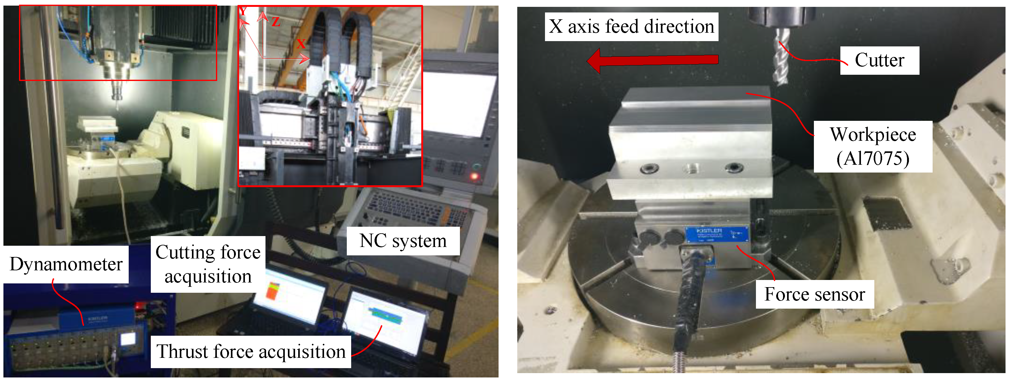
4.1. Experimental Setup

The experiment is carried out in an independently designed vertical machining center as shown in Figure 3. The X axis and Y axis are driven by the PMLM (Heidenhain, LMP28-200-3WDE-232, Traunreut, Germany). The X axis is chosen as the tested object. The main parameters of PMLM are shown in Table 1. The cutter parameters and milling parameters are shown in Table 2. The cutting force was measured by a dynamometer (model: Kistler 9265B, Winterthur, Switzerland) mounted between the aluminum alloy workpiece (model: 7075-T651) and machine table. The sampling frequency of cutting forces in the milling process is 20 kHz. The thrust force was measured by the monitoring software in the NC system and its sampling frequency is 1 kHz.

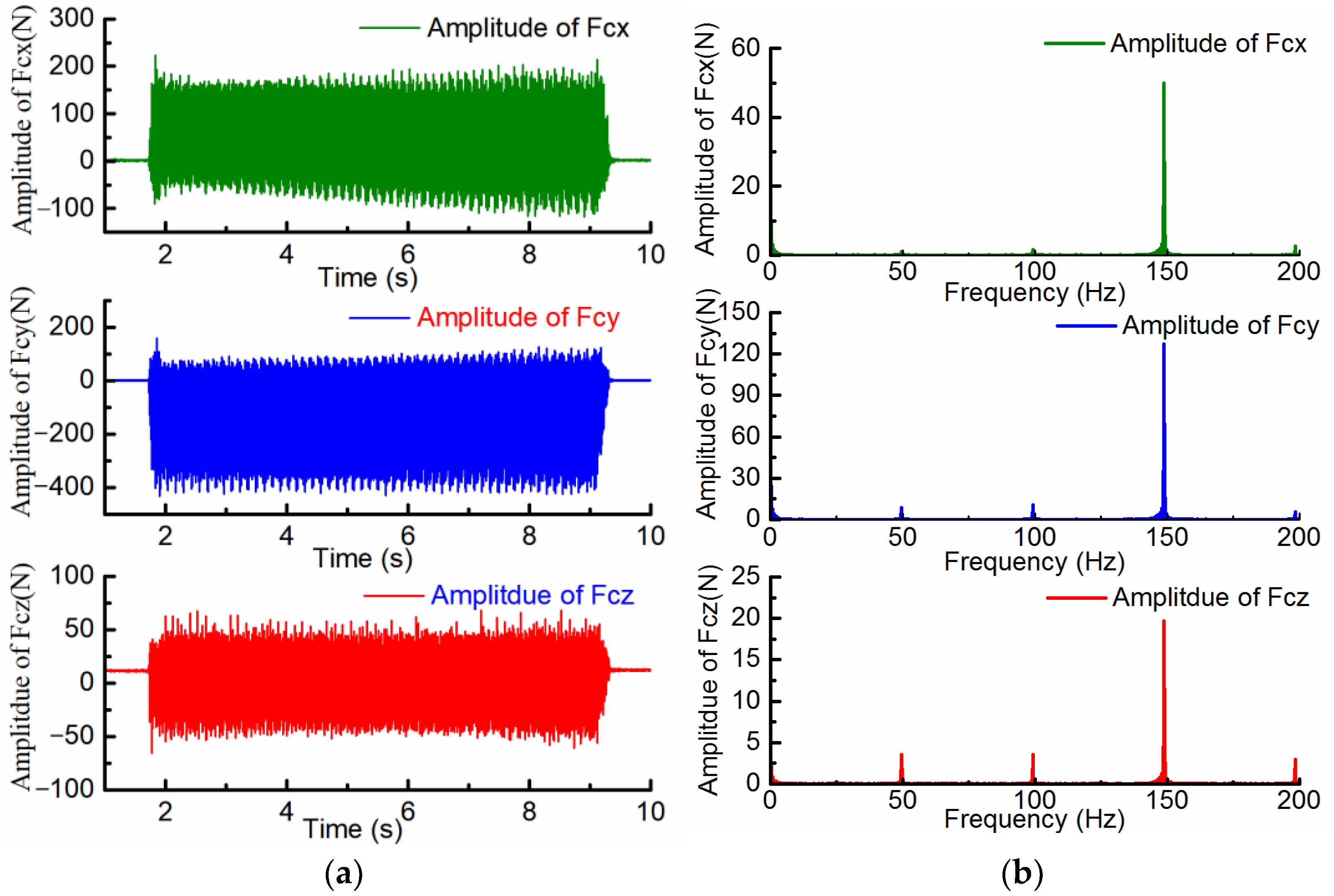
4.2. The Result of the Cutting Force

The results of the cutting force in the three directions are shown in Figure 4.
It can be seen from Figure 4 that there are obvious fluctuations in the cutting force. The amplitude of the cutting force in y direction is the largest and that in z direction is the smallest. The main harmonic components of the cutting force in the three directions are the three times harmonics of the rotation frequency, which are generated by the process of discontinuous contact between the cutter and the material. In addition, there are other harmonics in cutting force due to the tool eccentricity, spindle vibration and other factors.

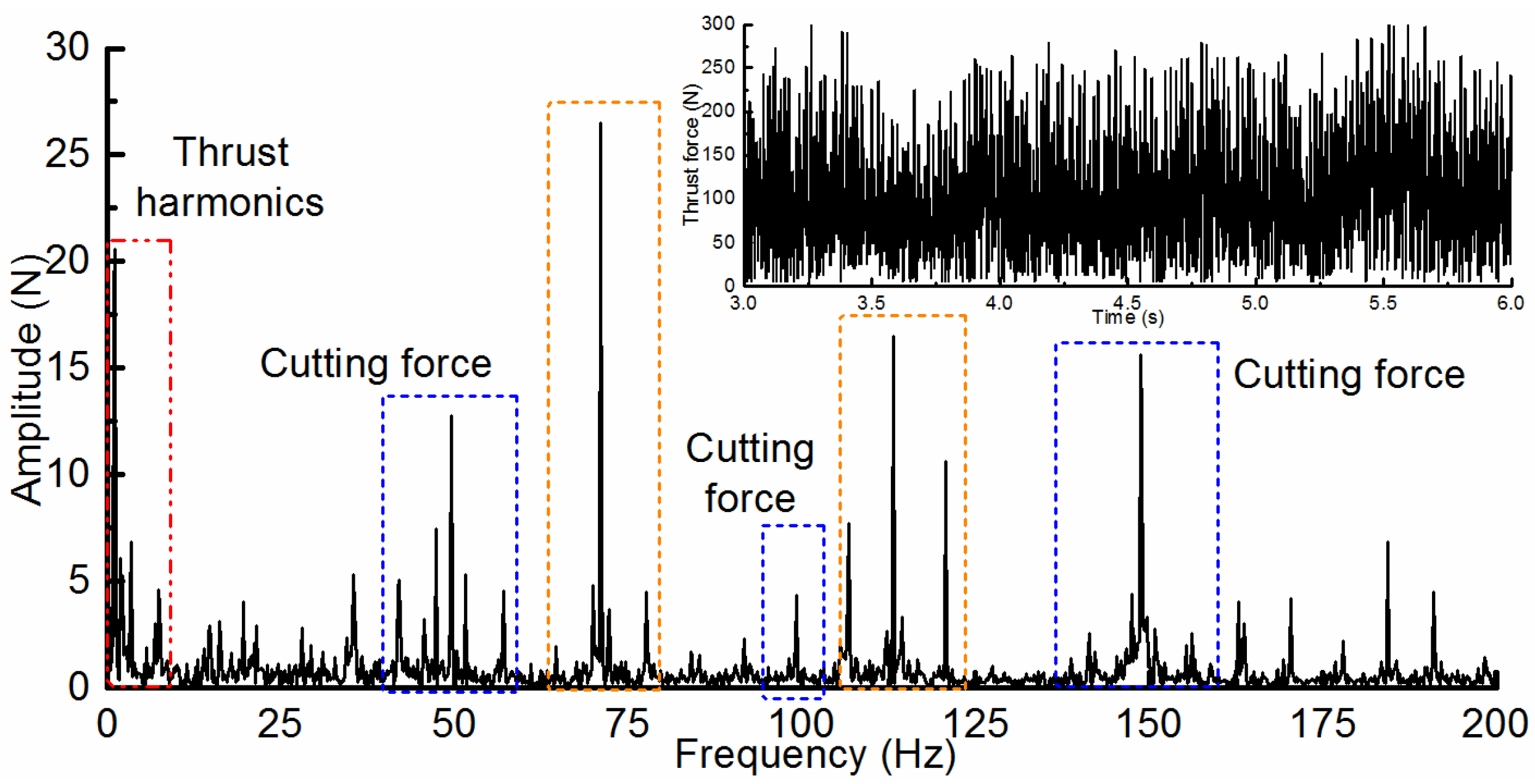
4.3. The Result of the Thrust Force in PMLM

The spectral analysis of the thrust force in the machining process is shown in Figure 5. The original main thrust force harmonics of PMLM are obtained as shown in Table 3 through the frequency spectrum analysis of the thrust force with the constant velocity.
It can be seen from Figure 5 and Table 3 that there are lots of thrust harmonics in addition to the cutting force and original thrust harmonics. There are many new thrust harmonics on both sides of the adjusted thrust caused by the cutting force. The new thrust force harmonics caused by the couplings between the cutting force and the original thrust harmonics are shown in Table 4, Table 5 and Table 6. Due to the limitations of experimental conditions, only the frequency is experimentally verified. In Table 4, Table 5 and Table 6, the coupling thrust harmonics of different components are separated by the frequency characteristics from experimental data.
It can be obtained from Table 4, Table 5 and Table 6 that the max deviation between the theoretical and test results of the frequencies of the new thrust harmonics is only 2.03%, which proves the validity of the previous theoretical analysis.

4.4. The Result of the Dynamic Precision of the Direct-Driven Feed System

The displacement fluctuation of the direct drive feed system in the machining process is shown in Figure 6. The displacement with constant velocity in the machining process is extracted for the spectral analysis as shown in Figure 7.
It can be seen from Figure 6 and Figure 7 that there are more obvious displacement fluctuations for the direct drive feed system because of the effects of the machining process. The spectral distribution of displacement fluctuation is basically consistent with that of thrust harmonics.

5. Discussions

(1)
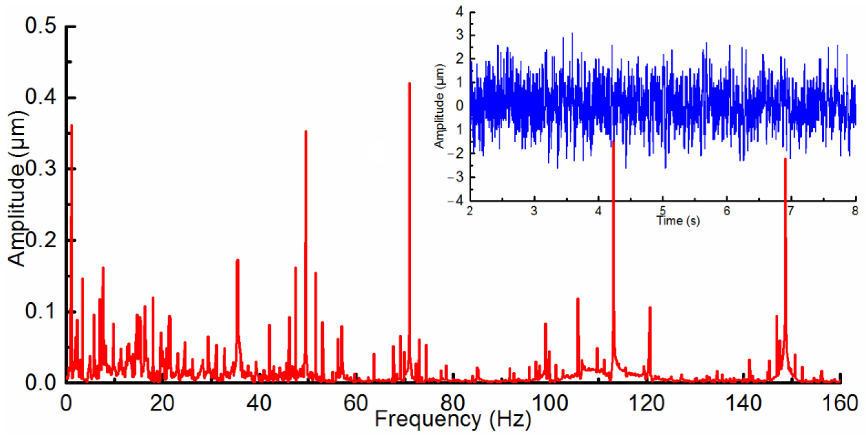
It can be seen from Figure 5 and Figure 7 that there are a large number of thrust harmonics and displacement fluctuations caused by other unknown factors. The modal analysis of the machine tool is carried out, and the modal distribution within 200Hz is shown in Table 7. It can be obtained from Table 7, Figure 5 and Figure 7 that several mechanical vibration modes (such as 36.32 Hz, 50.92 Hz, 72.42 Hz, and 113.65 Hz) are excited during the machining process, which aggravates electromechanical couplings, leading to much more thrust harmonics and displacement fluctuations.
(2)
Thrust spectrum of PMSLM with different conditions is shown in Figure 8. Figure 8a is the thrust spectrum only considering the cutting force and thrust harmonics. Figure 8b is the thrust spectrum considering the main mechanical vibrations of the machine tool. Figure 8c is the thrust spectrum considering the couplings caused by the cutting force.
It can be seen from Figure 8 that the cutting force will be coupled with the original thrust harmonics of the direct drive feed system, leading to more new paired thrust harmonics. Furthermore, more mechanical models will be excited during the machining process, aggravating the thrust fluctuation.
(3)
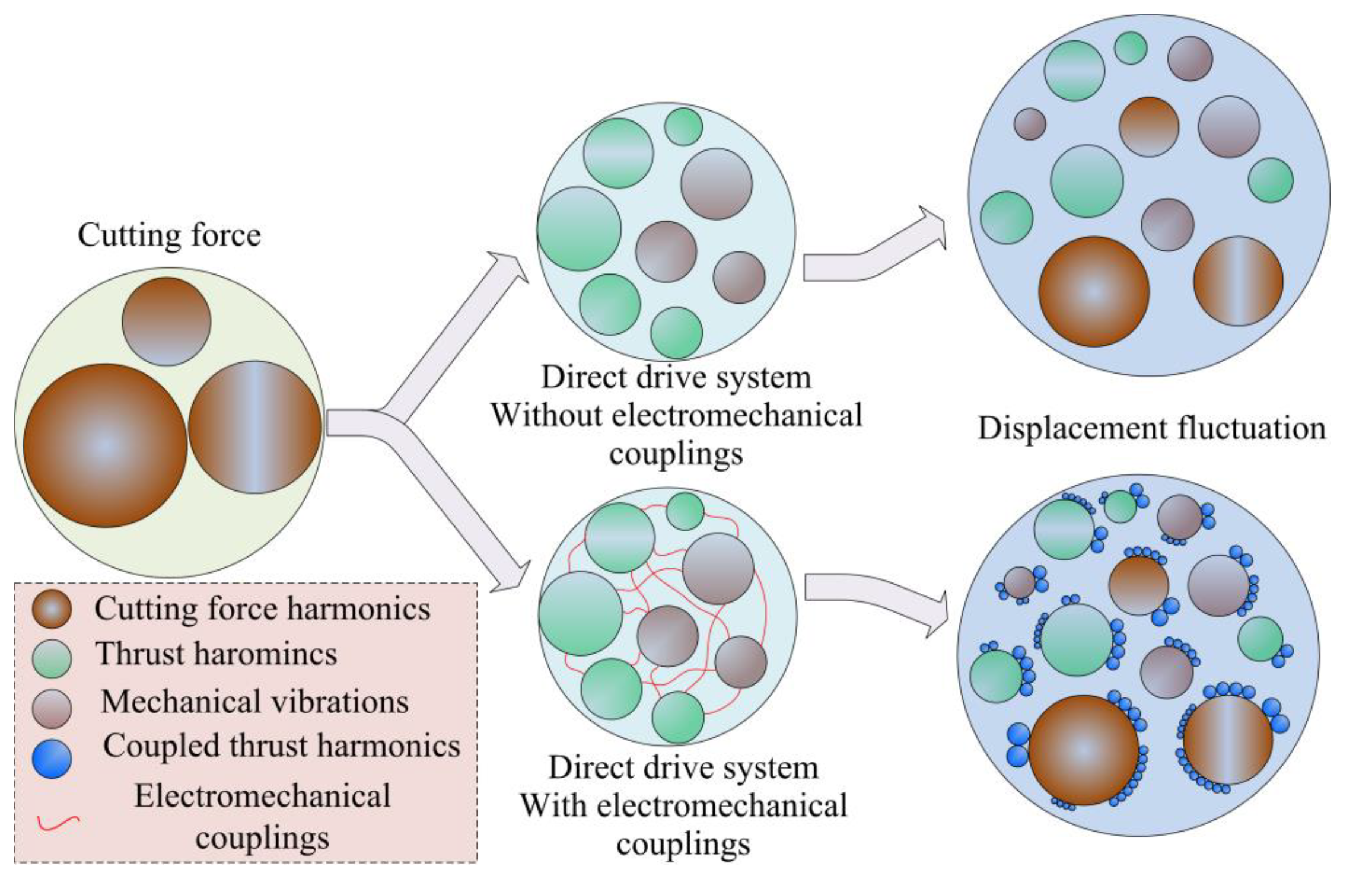
In the direct drive feed system, there are dynamic electromechanical couplings between the servo system and the mechanical system. The thrust harmonics directly act on the mechanical system, leading to obvious displacement fluctuation. Meanwhile, mechanical vibrations will affect the thrust force characteristics through the air-gap fluctuation and the feedback signal. In the machining process, the electromechanical coupling will deteriorate the influence of the cutting force harmonics on the mechanical system as shown in Figure 9. Lots of paired new thrust harmonics, which are produced by the couplings between the cutting force and original thrust harmonics, will appear on both sides of the adjusted thrust due to the cutting force. The influence of the machining process on the mechanical system will be extended from the discrete frequency point caused by the cutting force to approximate frequency band caused by the thrust force, affecting the dynamic precision of the feed system and the cutting stability of the machine tool.
In the machining process of the complex parts (such as the impeller), the cutting parameters, feed velocity, and spatial position of the feed axis are constantly changing. The cutting force, thrust force, and mechanical characteristics are constantly changing. The coupled strength of different coupling loops is different. Therefore, in the high-speed machine tool with the direct drive feed system, more attention should be paid to the influence of the machining process on the internal coupling problem of the feed system to optimize the machining path and cutting parameters.

6. Conclusions

In this paper, the effects of the machining process on the thrust force and mechanical characteristics of the direct drive feed system are researched. The main conclusions can be obtained as follows.
(1)
The dynamic electromechanical couplings between the servo system and mechanical system in the direct drive feed system will aggravate the effects of the machining process on the thrust force and mechanical characteristics of the feed system. The cutting force harmonics with multi-frequencies will be coupled with the non-linearity of the drive circuit and motor structure through the mechanical vibrations. A large number of new paired thrust harmonics will be produced. The frequencies of these new coupled thrust harmonics are related to the frequencies of the original thrust force harmonics and these of the mechanical vibrations caused by the cutting force harmonics.
(2)
The influence of the machining process on the direct drive system will be extended from the discrete frequency point caused by the cutting force to approximate frequency band caused by the thrust force, which will propose higher requirements for the control system. Especially if the frequency of one of the thrust harmonics is close to a certain natural frequency of the machine tool, the resonance will be aroused, affecting the dynamic precision of the feed system and the cutting stability of the machine tool. In order to make full use of the performance advantages of the direct drive feed system in machine tools, it is necessary to consider the influence of the machining process taking account of the electromechanical couplings. Similar problems are more prominent in the feed system driven by the linear motor with a U-shaped bilateral stator.
The thrust force harmonics of the direct drive feed system in the machining process have unique frequency characteristics. The results in this paper are of great significance to the analysis and improvement of the dynamic errors for the direct drive system in practical engineering applications.

Author Contributions

Conceptualization, X.Y. and W.Z.; methodology, X.Y.; software, X.Y.; validation, X.Y., J.X. and W.Z.; formal analysis, J.L.; investigation, X.Y.; resources, X.Y. data curation, X.Y.; writing—original draft preparation, X.Y.; writing—review and editing, J.L. and J.X.; visualization, X.Y.; supervision, X.Y. and J.X.; project administration, X.Y. and W.Z.; funding acquisition, X.Y. All authors have read and agreed to the published version of the manuscript.

Funding

This research was funded by Youth Program of National Natural Science Foundation of China, Grant number 51905411, and Fundamental Research Funds for the Central Universities, Grant number G2020KY05114.

Data Availability Statement

Not applicable.

Conflicts of Interest

The authors declare no conflict of interest. The funders had no role in the design of the study; in the collection, analyses, or interpretation of data; in the writing of the manuscript; or in the decision to publish the results.

Nomenclature

LLength of the motor mover
HAHeight of the motor mover
hsThickness of the winding
τPitch of the permanent magnet
ElkBack electromotive force with load of k-phase coil
ikArmature current of k-phase coil
LaSelf-inductance of a-phase
LcSelf-inductance of c-phase
MacMutual inductance between a-phase and c-phase
NCoil turns
F0Nominal thrust force
xmMechanical vibration in feed direction caused by the thrust force
θmxRoll vibration caused by the thrust force
θmyPitch vibration caused by the thrust force
θmzYaw vibration caused by the thrust force
g’Actual height of the air-gap considering the pitch
xi(s)Complex form of the command signal
Gp(s)Controller of the position loop
FcxCutting force along x axis
FczCutting force along z axis
FcxjAmplitude of the cutting force along x axis
φcxjPhase of the cutting force along x axis
ωcyjFrequency of the cutting force along y axis
FczjAmplitude of the cutting force along z axis
φczjPhase of the cutting force along z axis
LmbWidth of the motor mover
ArAmplitude of the roll vibration
ApAmplitude of the pitch vibration
iqce0Amplitude of the regulated current
τsTooth pitch
hThickness of the permanent magnet
wpWidth of the permanent magnet
gHeight of the air-gap
EmkBack electromotive force without load of k-phase coil
vVelocity
LbSelf-inductance of b-phase
MabMutual inductance between a-phase and b-phase
MbcMutual inductance between b-phase and c-phase
lWidth of the coil
FmrThrust harmonics
xcMechanical vibration in feed direction caused by the cutting force
θcxRoll vibration caused by the cutting force
θcyPitch vibration caused by the cutting force
θczYaw vibration caused by the cutting force
LmbWidth of the motor mover.
xe(s)Complex forms of the deviation signal
Gv(s)Controller of the velocity loop
FcxCutting force along y axis
wsWidth of the slot opening
ωcxjFrequency of the cutting force along x axis
FcyjAmplitude of the cutting force along y axis
φcyjPhase of the cutting force along y axis
ωczjFrequency of the cutting force along z axis
BrResidual flux density
hThickness of the permanent magnet
ωr0Angular frequency of the roll vibration
ωp0Angular frequency of the pitch vibration

References

  1. Altintas, Y.; Verl, A.; Brecher, C.; Uriarte, L.; Pritschow, G. Machine tool feed drives. CIRP Ann.—Manuf. Technol. 2011, 60, 779–796. [Google Scholar] [CrossRef]
  2. Yang, X.J.; Song, B.F.; Xuan, J.L. Effects of the mechanical vibrations on the thrust force characteristics for the PMLM driven motion system. Mech. Syst. Signal Process. 2022, 175, 109110. [Google Scholar] [CrossRef]
  3. Wang, W.T.; Zhao, J.W.; Song, J.C.; Dong, F.; Zong, K.F.; Li, G.H. Thrust performance improvement for PMSLM through double-layer reverse skewed coil and WRF-MKH method. IEEE/ASME Trans. Mechatron. 2020, 25, 2950–2960. [Google Scholar] [CrossRef]
  4. Min, S.G.; Sarlioglu, B. Analytical Prediction and Multiconstrained Nonlinear Optimization of Slotted Linear PM Motors Taking Into Account Two-Dimensional End Effects. IEEE Trans. Ind. Electron. 2020, 67, 2965–2976. [Google Scholar] [CrossRef]
  5. Zhao, J.W.; Wang, L.J.; Dong, F.; He, Z.Y.; Song, J.C. Robust High Bandwidth Current Regulation for Permanent Magnet Synchronous Linear Motor Drivers by Using Two-Degree-of-Freedom Controller and Thrust Ripple Observer. IEEE Trans. Ind. Electron. 2020, 67, 1804–1812. [Google Scholar] [CrossRef]
  6. Zhao, W.X.; Yang, A.C.; Ji, J.H.; Chen, Q.; Zhu, J.H. Modified Flux Linkage Observer for Sensorless Direct Thrust Force Control of Linear Vernier Permanent Magnet Motor. IEEE Trans. Power Electron. 2019, 34, 7800–7811. [Google Scholar] [CrossRef]
  7. Chen, S.Y.; Chiang, H.H.; Liu, T.S.; Chang, C.H. Precision motion control of permanent magnet linear synchronous motors using adaptive fuzzy fractional-order sliding-mode control. IEEE/ASME Trans. Mechatron. 2019, 24, 741–752. [Google Scholar] [CrossRef]
  8. He, Z.Y.; Dong, F.; Zhao, J.W.; Wang, L.J.; Song, J.C.; Wang, Q.J. Thrust Ripple Reduction in Permanent Magnet Synchronous Linear Motor Based on Tuned Viscoelastic Damper. IEEE Trans. Ind. Electron. 2019, 66, 977–987. [Google Scholar] [CrossRef]
  9. Yang, R.; Wang, M.Y.; Li, L.Y.; Zenggu, Y.M.; Jiang, J.L. Integrated Uncertainty/Disturbance Compensation with Second-Order Sliding-Mode Observer for PMLSM-Driven Motion Stage. IEEE Trans. Power Electron. 2019, 33, 2597–2607. [Google Scholar] [CrossRef]
  10. Yang, R.; Wang, M.Y.; Li, L.Y.; Wang, G.L.; Zhong, C.B. Robust Predictive Current Control of PMLSM With Extended State Modeling Based Kalman Filter: For Time-Varying Disturbance Rejection. IEEE Trans. Power Electron. 2020, 35, 2208–2221. [Google Scholar] [CrossRef]
  11. Wojciechowski, S.; Matuszak, M.; Powałka, B.; Madajewski, M.; Maruda, R.W.; Krolczyk, G.M. Prediction of cutting forces during micro end milling considering chip thickness accumulation. Int. J. Mach. Tools Manuf. 2019, 147, 103466. [Google Scholar] [CrossRef]
  12. Chen, Y.; Lu, J.; Deng, Q.; Ma, J.; Liao, X. Modeling study of milling force considering tool runout at different types of radial cutting depth. J. Manuf. Process. 2022, 76, 486–503. [Google Scholar] [CrossRef]
  13. Wan, M.; Wang, Y.T.; Zhang, W.H.; Yang, Y.; Dang, J.W. Prediction of chatter stability for multiple-delay milling system under different cutting force models. Int. J. Mach. Tools Manuf. 2011, 51, 281–295. [Google Scholar] [CrossRef]
  14. Dang, J.W.; Zhang, W.H.; Yang, Y.; Wan, M. Cutting force modeling for flat end milling including bottom edge cutting effect. Int. J. Mach. Tools Manuf. 2010, 50, 986–997. [Google Scholar] [CrossRef]
  15. Wang, B.; Liu, Z.; Cai, Y.; Luo, X.; Ma, H.; Song, Q.; Xiong, Z. Advancements in material removal mechanism and surface integrity of high speed metal cutting: A review. Int. J. Mach. Tools Manuf. 2021, 166, 103744. [Google Scholar] [CrossRef]
  16. Liang, T.; Lu, D.; Yang, X.; Zhang, J.; Ma, X.; Zhao, W. Feed fluctuation of ball screw feed systems and its effects on part surface quality in machine tools. Int. J. Mach. Tools Manuf. 2016, 101, 1–9. [Google Scholar] [CrossRef]
  17. Neugebauer, R.; Denkena, B.; Wegener, K. Mechatronic Systems for Machine Tools. CIRP Ann.—Manuf. Technol. 2007, 56, 657–686. [Google Scholar] [CrossRef]
  18. Ramon, M.; Giacomo, B. Mechatronic Analysis of Machine Tools. Proc. JMechE Part B J. Eng. Manuf. 2006, 220, 345–353. [Google Scholar]
  19. Weck, M.; Krueger, P.; Brecher, C. Limits for controller settings with electric linear direct drives. Int. J. Mach. Tools Manuf. 2001, 41, 65–88. [Google Scholar] [CrossRef]
  20. Szolc, T.; Konowrocki, R.; Michajłow, M.; Pręgowska, A. An investigation of the dynamic electromechanical coupling effects in machine drive systems driven by asynchronous motors. Mech. Syst. Signal Process. 2014, 49, 118–134. [Google Scholar] [CrossRef]
  21. Yang, X.J.; Lu, D.; Liu, H.; Zhao, W.H. Integrated modeling and analysis of the multiple electromechanical couplings for the direct driven feed system in machine tools. Mech. Syst. Signal Process. 2018, 106, 140–157. [Google Scholar] [CrossRef]
  22. Li, B.; Tian, X.; Zhang, M. Modeling and multi-objective optimization of cutting parameters in the high-speed milling using RSM and improved TLBO algorithm. Int. J. Adv. Manuf. Technol. 2020, 111, 1–13. [Google Scholar] [CrossRef]
  23. Kundrak, J.; Karpuschewski, B.; P’almai, Z. The energetic characteristics of milling with changing cross-section in the definition of specific cutting force by FEM method. CIRP J. Manuf. Sci. Technol. 2021, 32, 61–69. [Google Scholar] [CrossRef]
  24. Liu, Y.; Xiong, Z.H.; Liu, Z.Q. Stochastic cutting force modeling and prediction in machining. J. Manuf. Sci. E-Trans. ASME 2020, 142, 1–34. [Google Scholar] [CrossRef]
  25. Fu, D.; Xu, Y.; Gillon, F.; Gong, J.; Bracikowski, N. Presentation of a novel transverse-flux permanent magnet linear motor and its magnetic field analysis based on Schwarz-christoffel mapping method. IEEE Trans. Magn. 2018, 54, 6000204. [Google Scholar] [CrossRef]
  26. Zeng, L.; Chen, X.; Li, X.; Jiang, W.; Luo, X. A thrust force analysis method for permanent magnet linear motor using Schwarz-Christoffel mapping and considering slotting effect, end effect, and magnet Shape. IEEE Trans. Mag. 2015, 51, 8107609. [Google Scholar] [CrossRef]
  27. Yang, X.J.; Lu, D.; Zhao, W.H. Decoupling and effects of the mechanical vibration on the dynamic precision for the direct-driven machine tool. Int. J. Adv. Manuf. Technol. 2018, 95, 3243–3258. [Google Scholar] [CrossRef]
  28. Yang, X.J.; Lu, D.; Zhang, J.; Zhao, W.H. Investigation on the displacement fluctuation of the linear motor feed system considering the linear encoder vibration. Int. J. Mach. Tools Manuf. 2015, 98, 33–40. [Google Scholar] [CrossRef]
Figure 1. The analytical model of the direct drive feed system.
Processes 11 00017 g001
Figure 2. The electromechanical coupling considering the machining process in the direct drive feed system.
Processes 11 00017 g002
Figure 3. The experimental object for the direct drive feed system.
Processes 11 00017 g003
Figure 4. The results of the cutting force in three directions. (a) in time domain; (b) in frequency domain.
Processes 11 00017 g004
Figure 5. The spectral analysis of the thrust force in the machining process.
Processes 11 00017 g005
Figure 6. The displacement fluctuation of the direct drive feed system.
Processes 11 00017 g006
Figure 7. The spectral diagram of the displacement fluctuation of the direct drive feed system in the machining process.
Processes 11 00017 g007
Figure 8. Thrust spectrum of PMLM with different conditions.
Processes 11 00017 g008
Figure 9. The effects of the machining process on the direct drive feed system.
Processes 11 00017 g009
Table 1. The main parameters of direct drive feed system.
NameValue
Position travel (mm)600
Continuous force (N)2920
Peak force (N)11,500
Force constant (N/A)165
Height of the air-gap (mm)1.0
Length of mover (mm)255
Pitch of permanent magnet (mm)22
Tooth pitch (mm)13
Acceleration (m/s/s)15
Max velocity (m/min)90
Table 2. The main parameters in the machining process.
NameValue
WorkpieceMaterialAl7075
Cutter parametersTooth number3
Diameter (mm)16
Milling parametersTypeSide milling
Feed rate (mm/min)1500
Spindle speed (r/min)3000
ap (mm)2
ac (mm)2
Table 3. The original main thrust harmonics.
OrderSourceFrequency (Hz)Amplitude(μm)
1End effect1.0820.58
2Slotting effect1.916.11
3Drive circuit3.426.84
4Drive circuit6.741.53
5Slotting effect, drive circuit7.404.62
Table 4. The coupling thrust force caused by the first-order cutting force.
OrderSourceTest Results (Hz)Theoretical Calculations (Hz)Deviation (%)
1Air-gap Fluctuation35.4135.901.36
2Air-gap Fluctuation39.2439.320.20
3Air-gap Fluctuation42.0741.940.31
4Full-loop Control42.0742.180.26
5Air-gap Fluctuation43.2442.741.17
6Full-loop Control42.9042.840.14
7Air-gap Fluctuation44.7443.852.03
8Air-gap Fluctuation45.5745.760.41
9Full-loop Control46.0846.160.17
10Full-loop Control47.4147.660.52
11Full-loop Control51.5751.490.15
12Full-loop Control53.0752.990.15
13Air-gap Fluctuation53.0753.40.62
14Air-gap Fluctuation55.0755.310.43
15Full-loop Control57.2456.321.63
16Air-gap Fluctuation56.2456.420.32
17Full-loop Control56.2456.981.30
18Air-gap Fluctuation57.0757.220.26
19Air-gap Fluctuation59.5759.840.45
20Air-gap Fluctuation63.4163.260.24
Table 5. The coupling thrust force caused by the second-order cutting force.
OrderSourceTest Results (Hz)Theoretical Calculations (Hz)Deviation (%)
1Air-gap Fluctuation85.2385.550.37
2Air-gap Fluctuation88.9088.970.08
3Air-gap Fluctuation91.7391.590.15
4Full-loop Control91.7391.830.11
5Air-gap Fluctuation92.5792.390.19
6Full-loop Control92.5792.490.09
7Air-gap Fluctuation93.5793.50.07
8Air-gap Fluctuation95.2395.410.19
9Full-loop Control95.5695.810.26
10Full-loop Control97.0697.320.27
11Full-loop Control101.23101.140.09
12Full-loop Control102.73102.650.08
13Air-gap Fluctuation103.23103.050.17
14Air-gap Fluctuation104.73104.960.22
15Full-loop Control105.57105.970.38
16Air-gap Fluctuation106.06106.070.01
17Full-loop Control106.73106.630.09
18Air-gap Fluctuation106.73106.870.13
19Air-gap Fluctuation109.73109.490.22
20Air-gap Fluctuation113.06112.910.13
Table 6. The coupling thrust force caused by the third-order cutting force.
OrderSourceTest Results (Hz)Theoretical Calculations (Hz)Deviation (%)
1Air-gap Fluctuation134.89135.050.12
2Air-gap Fluctuation138.72138.470.18
3Air-gap Fluctuation141.39141.090.21
4Full-loop Control141.39141.330.04
5Air-gap Fluctuation142.22141.890.23
6Full-loop Control142.22141.990.16
7Air-gap Fluctuation142.89143.00.08
8Air-gap Fluctuation144.73144.910.12
9Full-loop Control145.39145.310.06
10Full-loop Control146.72146.820.07
11Full-loop Control150.89150.640.17
12Full-loop Control152.22152.150.05
13Air-gap Fluctuation152.22152.550.22
14Air-gap Fluctuation154.55154.460.06
15Full-loop Control155.39155.470.05
16Air-gap Fluctuation155.39155.570.12
17Full-loop Control156.22156.130.06
18Air-gap Fluctuation156.22156.370.10
19Air-gap Fluctuation158.89158.990.06
20Air-gap Fluctuation162.89162.410.30
Table 7. The modal distribution of the machine tool.
Order12345678
Frequency (Hz)17.0336.3250.9272.4297.54113.65161.13193.28
Disclaimer/Publisher’s Note: The statements, opinions and data contained in all publications are solely those of the individual author(s) and contributor(s) and not of MDPI and/or the editor(s). MDPI and/or the editor(s) disclaim responsibility for any injury to people or property resulting from any ideas, methods, instructions or products referred to in the content.

