Article

Downtime Reduction with Fast Restart Function in a Beverage Production System

by
Chaiyan Jettanasen
1,
Natthanon Phannil
1,
Suntiti Yoomak
1,
Surakit Thongsuk
2,
Sulee Bunjongjit
3 and
Atthapol Ngaopitakkul
1,*
1
King Mongkut’s Institute of Technology Ladkrabang, School of Engineering, Bangkok 10520, Thailand
2
Faculty of Industrial Technology, Rajabhat Rajanagarindra University, Chachoengsao 24000, Thailand
3
Faculty of Engineering, Rajamangala University of Technology Rattanakosin, Nakhon Pathom 73170, Thailand
*
Author to whom correspondence should be addressed.
Processes 2023, 11(1), 39; https://doi.org/10.3390/pr11010039
Submission received: 17 October 2022 / Revised: 13 December 2022 / Accepted: 19 December 2022 / Published: 24 December 2022

Abstract

:
Bottled-beverage production systems require considerable machinery and sophisticated control systems. A malfunction in the production system can result in machine stoppages, thereby decreasing productivity and resulting in the production output not meeting the required target. Therefore, the problem of frequent stoppages of the production system must be resolved. The ‘Fast Restart Function’ is a proposed feature that can help reduce machine downtime by decreasing the time required for the product to drain from the conveyor. In this study, using this strategy, the investigated manufacturing system’s efficiency increased from 86.81% to 90.29%, enabling an increase in the average production capacity by 27,187 bottles per day, i.e., a 3.48 percent increment of the daily capacity. When employed in inefficient production systems or systems facing frequent shutdowns, this system is of considerable value for mitigating production stoppages.

1. Introduction

‘Life cannot exist without water’—if we consider the human species itself, three-quarters of the human body is water. Thus, drinking a sufficient amount of clean water, i.e., 6–8 glasses per day, is beneficial to the body. However, water obtained from natural sources does not invariably guarantee cleanliness. Consumption of naturally-occurring un-purified water has been on the decline in modern society, particularly among the health-conscious people in this era, and consumption of bottled water is increasing. Clean and safe drinking water, a commodity that is easy to purchase, has directly impacted the drinking-water industry, leading to considerable industrial expansion. In Thailand, this product holds the largest market share among bottled beverages sold.
An important sales strategy used by drinking-water companies is to manufacture different sized products according to the needs of the consumers. The smaller package sizes are of 330, 600, and 1500 mL, whereas the bulk package sizes offer capacities of 6 L and 18 L, which are suitable for families and organizations. The 600-mL variant is the most widely-used product, especially in convenience stores and restaurants. In addition, drinking-water companies prefer the following: a PET (polyethylene terephthalate) bottle with an ergonomic design that makes the bottle more comfortable to grip and hold, a bright logo, and high-quality drinking water. Developing a handle with which the bottle is easy to carry is another important marketing strategy.
Currently, the drinking-water market in Thailand exceeds THB 20 billion with a growth rate of approximately 8% [1,2]. Expectedly, this product will experience an increase in demand from consumers who prefer convenience, speed, and cleanliness. However, entrepreneurs perceive an opportunity to expand further in the future, considering that, at present, only 30% of people purchase drinking water on a daily basis. The remaining 70% are still able to obtain their own drinking water from natural sources. As the practice of drinking water from natural water sources will reduce in importance due to natural limitations, including the lifestyle of modern people seeking safe and convenient consumption, the bottled water industry will expand further in the future. Therefore, the consumer market that fulfils 70% of its drinking-water needs from natural sources is a target market of great interest to Thai bottled-water operators.
Nowadays, the rapid pace of economic growth has resulted in increased business competition. The unlimited needs of humans are the driving force for acquiring new knowledge, thereby leading to the development of various technologies over time [3]. This economic expansion and the efforts of various industries have led to the development of high-capacity production machines to address the competition. In particular, the beverage industry in Thailand produces a wide variety of products, such as drinking water, fruit juices, and energy drinks, which face extreme market competition. To cater to the demand for large-volume products, continual production and sufficient product reserves for sales are essential. Therefore, the machinery used in the production system should have high productivity and efficiency. In addition, the production system should be clean and safe to ensure a large production volume and high quality of the products, which are fabricated according to the needs of customers.
For production of plastic bottled beverages [4,5], a wide range of machines for various processes have been utilized, starting from the reception of raw materials until the product is sorted for shipping. Different types of machines operate in different production processes depending on the form of the product. In a field study focusing on a drinking-water production system with a capacity of 34,000 bottles per hour, the average production efficiency was reportedly 86.81% of the production capacity, i.e., approximately 29,200 bottles per hour. Consequently, the productivity did not meet the set target, and the company exported a lesser amount of products than expected. This deterioration in production efficiency is caused by system failures, the jamming of materials used in production, the age of the machine, and several other factors [6], that result in the stoppage of the machine and production system. If the production system halts frequently, the production volume drastically reduces [6,7]. If these problems are resolved, the production system can fabricate products continuously, resulting in a higher efficiency, the ability to manufacture more products, and an overall positive effect on the production process [8,9,10]. Therefore, to solve the problem of frequent stoppage of the production system, the working patterns of the production system should be studied to analyse the cause of the problem, obtain a solution to the problem, and ensure that the production system can work continuously [11,12].
Several studies have focused on the development of each machine type for increasing the performance. Generally, plastic-bottle production lines feature a blow moulding machine, which is the first production machine of the system. A preform tube, which is the bottle raw material, is heated and moulded inside the mould. For the preform-tube heating, the optimum heating location and temperature of the preform tube must be taken into account [13]. Furthermore, the composition and thickness of the bottle affect the completion of the blow moulding process [13,14]. Thus, the bottle blow-moulding machine is one of the machines determining the speed of the production line [15]. In addition, as the liquid-filling process must take into account the appropriate volume and time, a filler machine has been developed. Each liquid has a different flow viscosity, resulting in different filling patterns and filling times. Kalidasan [16] designed an automatic product-filling machine, wherein the filling volume can be calculated according to the size of the bottle; this machine can be applied in the beverage, chemical, cosmetic, and pharmaceutical industries. Although the research advances the automation industry, these filler machines jam frequently and most of them are limited by minor problems. Nwadinobi [17] and Ben [18] have proposed solutions by designing autonomous maintenance that can solve the initial problem, reduce the downtime of the machine, and increase the working time. Moreover, because the filler machine determines the speed of the production line and should be capable of continuous and accurate operation, their efficient working can increase the efficiency of the whole production system. In addition, in the research reported by Ben [19], the relationship among the temperature, soaking time, and NaOH concentration of a bottle washer was investigated considering that in the beer industry, 80% of glass bottles are recycled. In this study, three washing ponds were utilized with temperatures of 60 °C, 80 °C and 60 °C, respectively and NaOH concentrations of 1.99%, 1.81% and 1.66%, respectively. The speed of the washer was studied at two values: 40,000 and 46,000 bottles per hour (BPH). At the speed of 40,000 BPH, the empty bottle inspector (EBI) rejected 4.18% of the total processed bottles, whereas at the speed of 46,000 BPH, the EBI rejected 8.44% of the total processed bottles.
This research investigated the production system of plastic bottled beverages and the working patterns of each machine to improve the work continuity and reduce the downtime of machines. Problems related to the production system’s operating time were analysed, and the results revealed that the draining of the product from the conveyor took considerable time. This resulted in the stoppage of the relevant machine. Moreover, the different speed of each machine in the production system caused downtime of certain machines because no raw material was supplied to the machine. Therefore, this study proposes a new functionality that can reduce the waiting time for product draining on the conveyor and reduce the machine downtime. The proposed function, named ‘Fast Restart Function’, increased the machine uptime, efficiency, and product yield. Thus, its implementation is expected to enhance the productivity and competitiveness of the plastic bottled beverage business.
The contributions of this paper are summarized as follows:
  • Study the production process and working principles of machines in the production of plastic bottled beverages in order to improve the efficiency of the production system.
  • A fast restart function is designed to reduce the waiting time to empty the bottle from the conveyor before the machine restarts.
  • The performance of the fast restart function was analysed to determine its application in the production system.
The rest of this paper is organized as follows: in Section 2, the beverage production system is presented to explain the position and function of each machine. Moreover, the operating speed of each machine is illustrated to provide an overview of the operation in the actual production system. Subsequently, the sensors are discussed in Section 3, describing the workflow for each machine and the waiting time when the machine must be stopped and restarted. In Section 4, a function to reduce the waiting time for a machine restart is introduced, named ‘Fast Restart Function’. This can reduce the waiting time for bottle draining in the conveyor, increase uptime and machine productivity, and increase the efficiency of the production system clearly. Finally, all results are summarized in Section 5.

2. The Plastic Bottled-Beverage Production System

Packaging beverages in plastic bottles is an extremely popular strategy to cater to the market due to its convenience of production and low production cost. Several types and working principles of machines are employed in the production system for plastic bottled beverages. In this study, the production system of plastic bottled beverages starts from the bottle production process to filling and delivery processes, as depicted in Figure 1a.

2.1. Production Machine of the Plastic Bottled-Beverage Production System

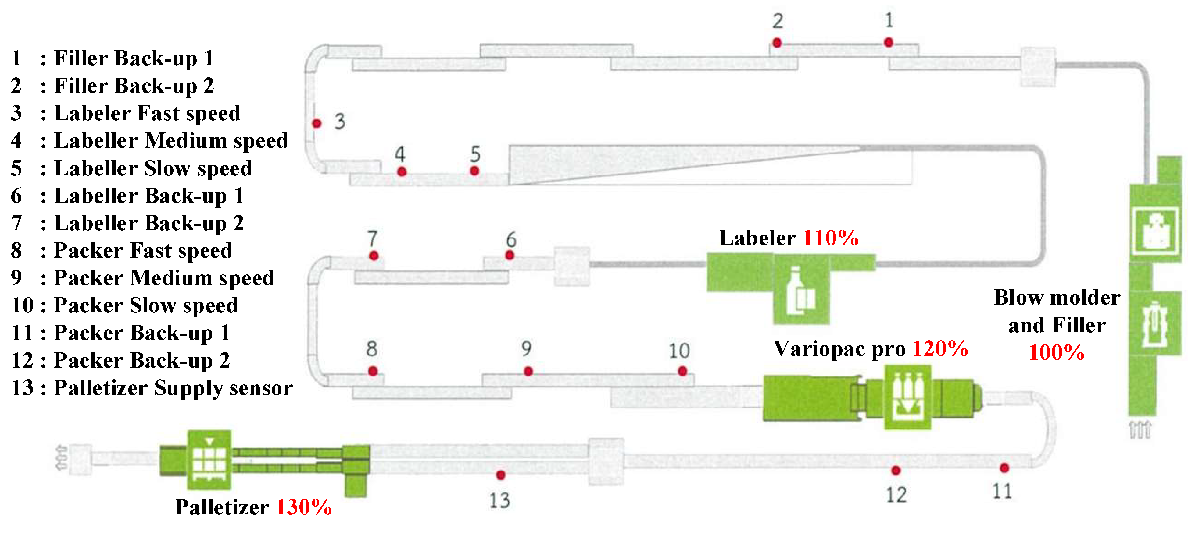
This beverage production system has six major machines: a blow moulding machine, a filler machine, an inspector machine, a labeller machine, a variopac machine, and a palletizer machine. Each machine serves a different function and has a specific place in the sequence of operation in accordance with the flowchart in Figure 1b. The raw materials and products are fed into the production system according to the relative position of the machines as follows:
The blow moulding machine (Number 1 in Figure 1a) is the first machine of the production system used for forming plastic bottles. It comprises three working parts: a preform tube pouring machine, a preform tube oven, and a bottle forming machine. In the working process of the blow moulding machine, preform tubes are inserted into the preform tube pouring machine and subsequently transferred through a conveyor to the preform oven for heating via high-pressure sodium lamps; this process softens the preform tube, making it easier to mould. Thereafter, they are transferred into the bottle forming machine to stretch the preform tube with high-pressure air at approximately 40 bar and a bottle mould.
The filler machine (Number 2 in Figure 1a) is a machine used for filling products and capping bottles. This machine is crucial to the production system. The filler machine consists of two working parts: the product filling part and bottle capping part. The filler machine’s working process starts after the finished formed bottle is sent to the filling process. This process fills products according to the specified quantity, and the products are subsequently sent to the bottle capping part before being sent to the conveyor for further processing.
The inspector machine (Number 3 in Figure 1a) is used to inspect bottles that have been filled with products. The filled bottles must be inspected for product quality to prevent defective products from entering the market. When a defective product is detected, it is removed from the production system. Product quality inspection at this stage is divided into two parts. First, the capping of the bottle is inspected using a high-speed camera that captures grayscale photographs. The image is compared using the light reflected on the bottle with the quality bottle. Thereafter, image aberrations are checked and analysed according to the following criteria: First, a cap is present on every bottle, the bottle cap is not tilted or warped, the bottle cap lock is not broken, and the bottle cap is completely present. Second, the product is filled in the bottle to the required level. The detector emits gamma rays to measure the intensity of the radiation passing through the bottle in different regions. The radiation intensity is reduced if the product is present in the area.
The labeller machine (Number 4 in Figure 1a) is used to label each product’s trademark. The labeller machine sequentially conveys individual bottles via the conveyor into the machine, attaches the label of the product, and passes each bottle through the labelling inspector again to verify the correct labelling.
The variopac machine (Number 5 in Figure 1a) is a bottle packer that arranges the bottles on the conveyor, wraps each bottle with transparent film, places them into the hot air incubator to shrink the film, and finally wraps them in a pack of 12 bottles (4 × 3 bottles).
The palletizer machine (Number 6 in Figure 1a) is the final machine that processes the bottles for easy transport and storage. Products obtained via this process can be sold immediately to the market.

2.2. Working Speed of the Plastic Bottled-Beverage Production System

The filler machine’s maximum speed is used to calculate the manufacturing capacity of 600-mL plastic bottles of beverages, which is 34,000 bottles per hour. Each machine has a different production speed, as shown in Table 1. The production speed of the labeller, variopac, and palletizer machines can be adjusted according to the number of bottles accumulated in the conveyor.
A schematic diagram of the machine speed and sensor position of the production system is illustrated in Figure 2. Each machine has a production speed that differ by 10% from each other in order of their position in the production line. The blow moulding and filler machines have the lowest production speed because they are the primary machines in this line. Other machines require higher production speeds to move the bottle in the conveyor to ensure no overflows and continual production. The operation of each machine is controlled by sensors that detect the number of bottles in the conveyor; the working principle of these sensors are presented in the following section.

3. The Production System

The control system of each machine receives signals from sensors at various locations along the conveyor. The control system is utilized to start, stop, and adjust the production speed of the machines. Each sensor detects the bottle quantity in the conveyor and ensures communication between the conveyor and machine. These machines receive commands via the sensor signals. Two types of sensors are used for machine control: a backup sensor and a speed sensor. The backup sensor measures the bottle quantity at the end of the machine to prevent the product from overflowing onto the conveyor, while the speed sensor measures the bottle quantity before entering the machine to ensure that an adequate number of bottles are fed into the machine, and the speed of the machine is controlled according to the measured bottle volume.

3.1. Starting and Stopping Control

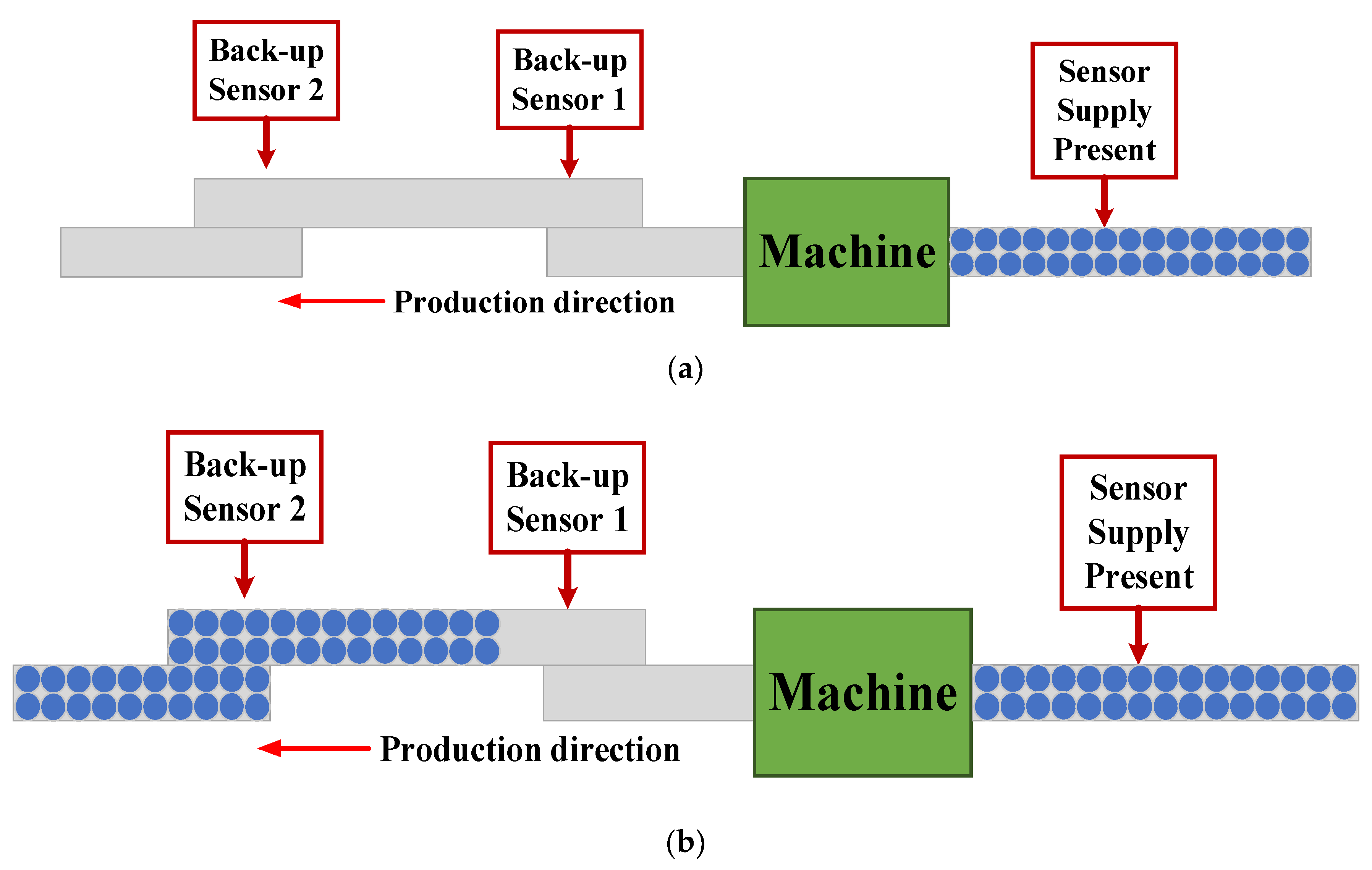
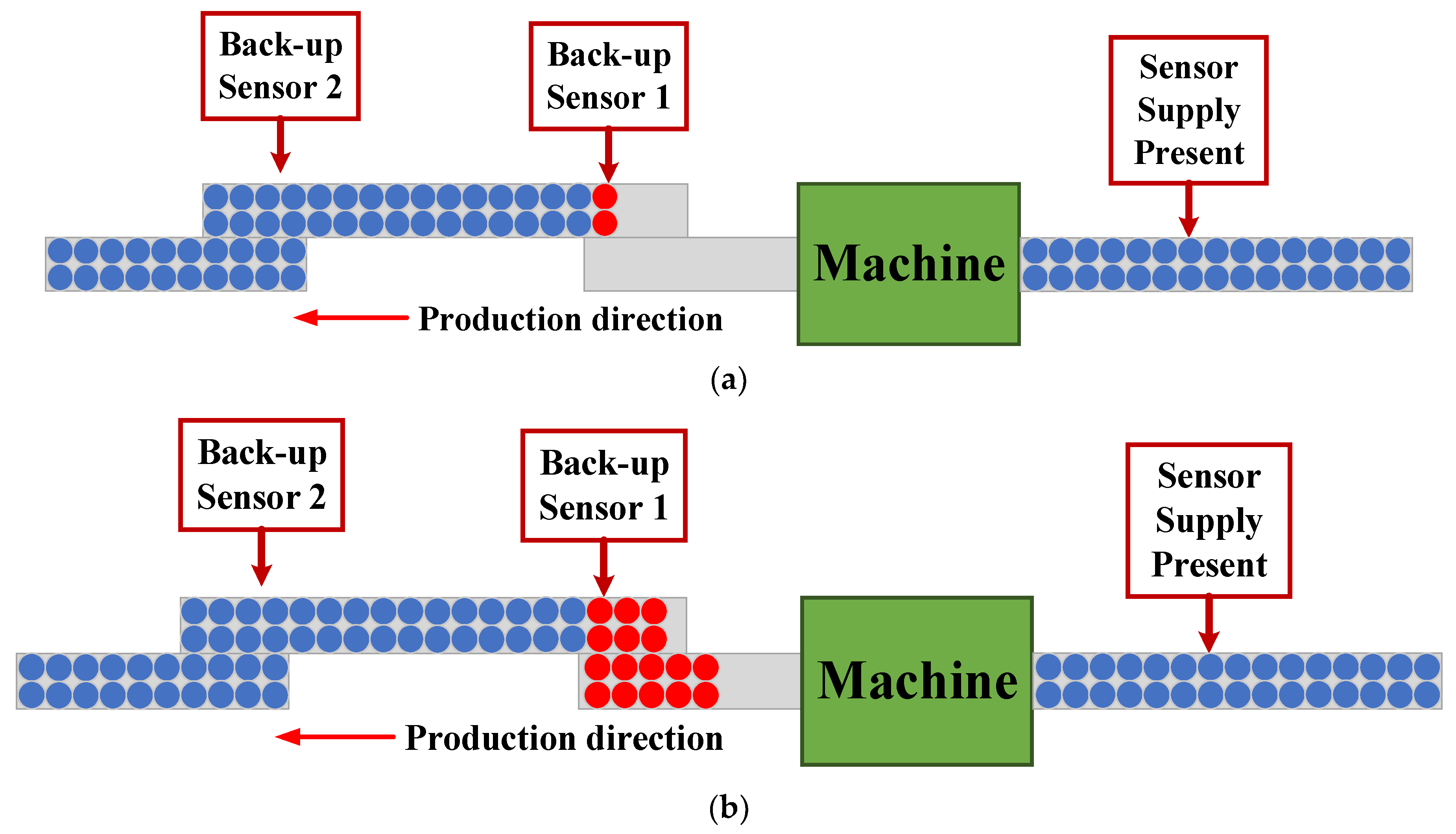
The machine can be started and stopped by analysing the commands from both sensors. The machine can be started in two cases, as depicted in Figure 3, which are the case that raw materials are ready for production and no bottles accumulate in the conveyor, and the case that raw materials are ready for production and bottles are collected in the conveyor. When the bottles in the conveyor reach the back-up machine sensor 1, the machine will stop working immediately to prevent the bottle from overflowing the conveyor, as presented in Figure 4.

3.2. Production Speed Control

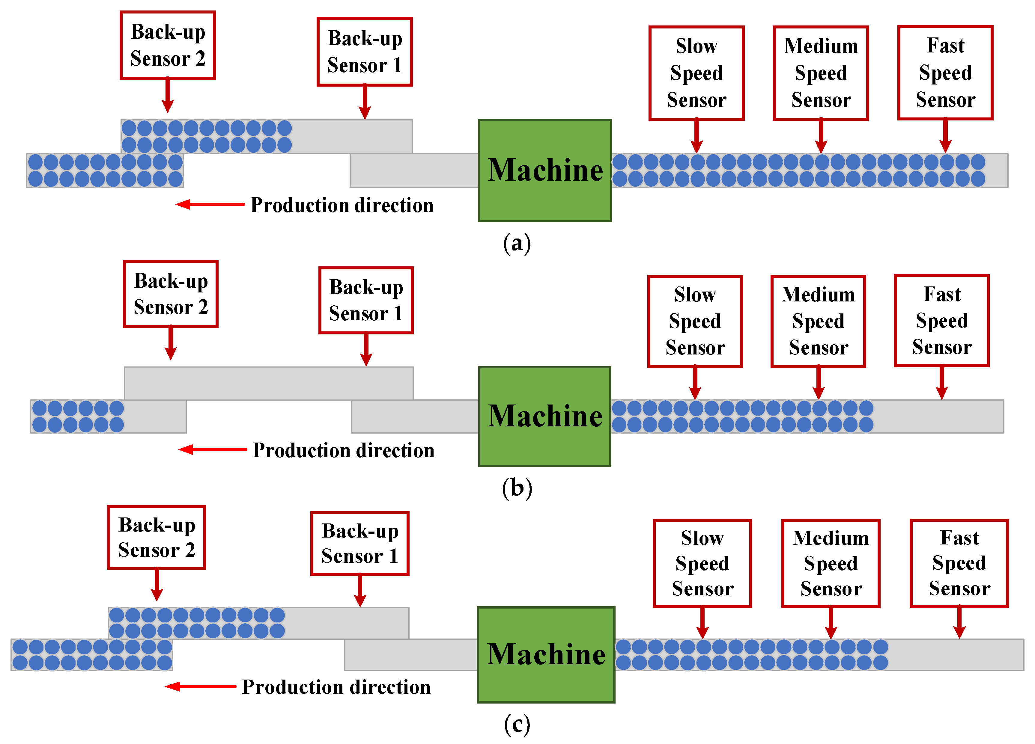
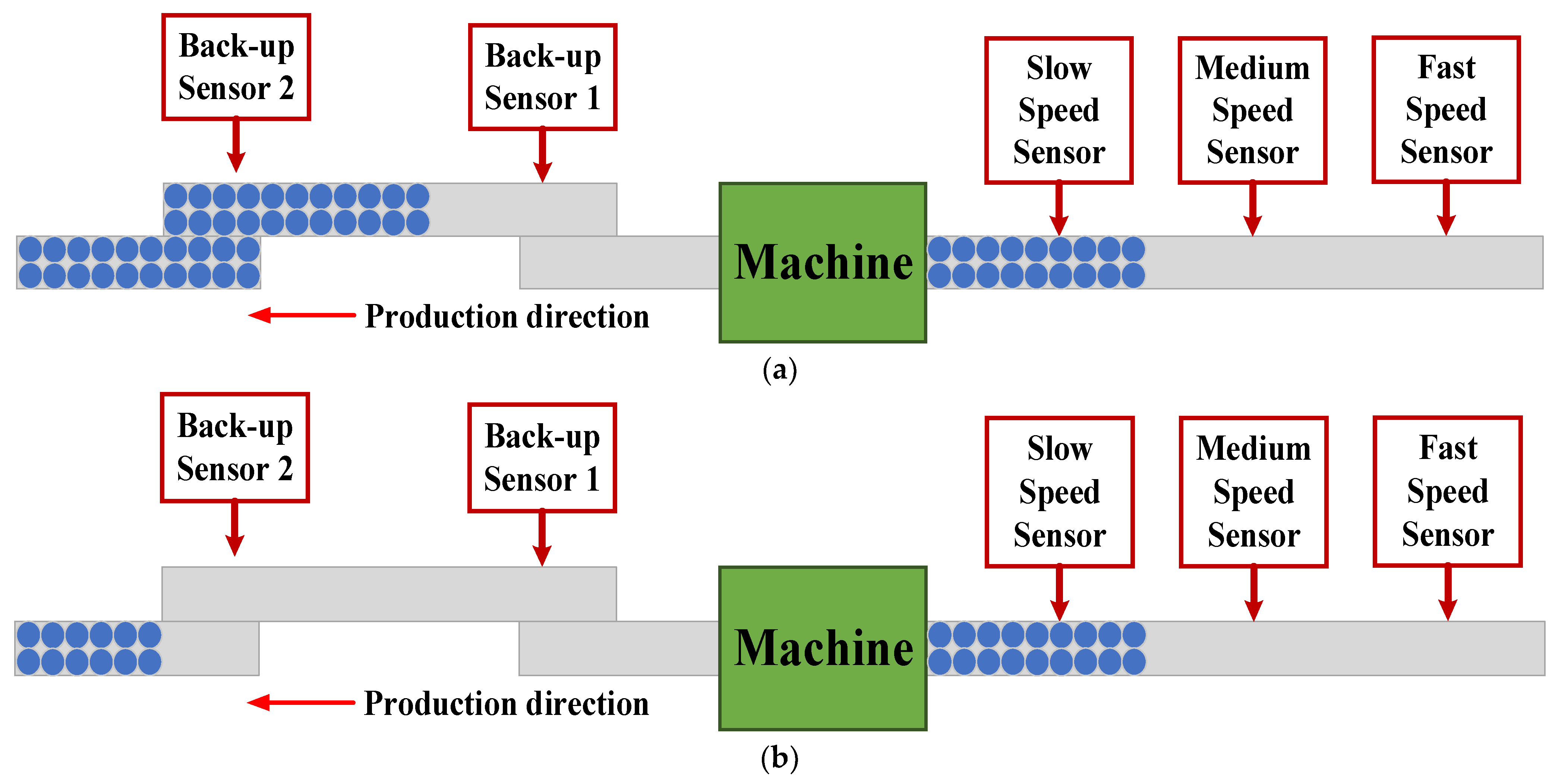
Speed sensors are used with the labeller and variopac machines to adjust the machine’s production speed based on three levels: fast, medium, and slow. The palletizer machine uses a supply sensor, which has the same function as the speed sensor, i.e., to inspect the bottle packs that flow along the conveyor. For the production speed control, the signals from all five sensors are employed, as shown in Table 2. The machine will automatically start when the backup sensor 1 status is ‘ON’ and the slow speed sensor status is ‘OFF’. The status of both sensors confirms that the system has raw materials to feed the machine and the conveyor space behind the machine is sufficient to support the resulting product. If the operator wants the machine to run at high speed, the system must ensure sufficient raw materials and space behind the machine. The raw materials must be as many as the fast speed sensor, and the backup sensor 2 has an ‘ON’ status, as displayed in Figure 5. The production speed will decrease to a medium speed if the conveyor is full, thereby causing the backup sensor 2 status to reflect an ‘OFF’ status or the fast speed sensor an ‘ON’ status, as indicated in Figure 6. If the fast and medium speed sensor has an ‘ON’ status, the production speed will be operated at a slow speed, as demonstrated in Figure 7. Finally, if both backup sensors have an ‘OFF’ status, the machine will stop receiving raw materials while also continuously working to clear the remaining raw materials from the machine, and subsequently, halts operation. After the machine has stopped working and solved the problems in the system, the machine can restart when the machine in the next step is run to reduce the product volume in the conveyor until the backup sensor 2 reflects an ‘ON’ status. Thus, the machine can restart operations.

3.3. Downtime for Machine-Restart Waiting

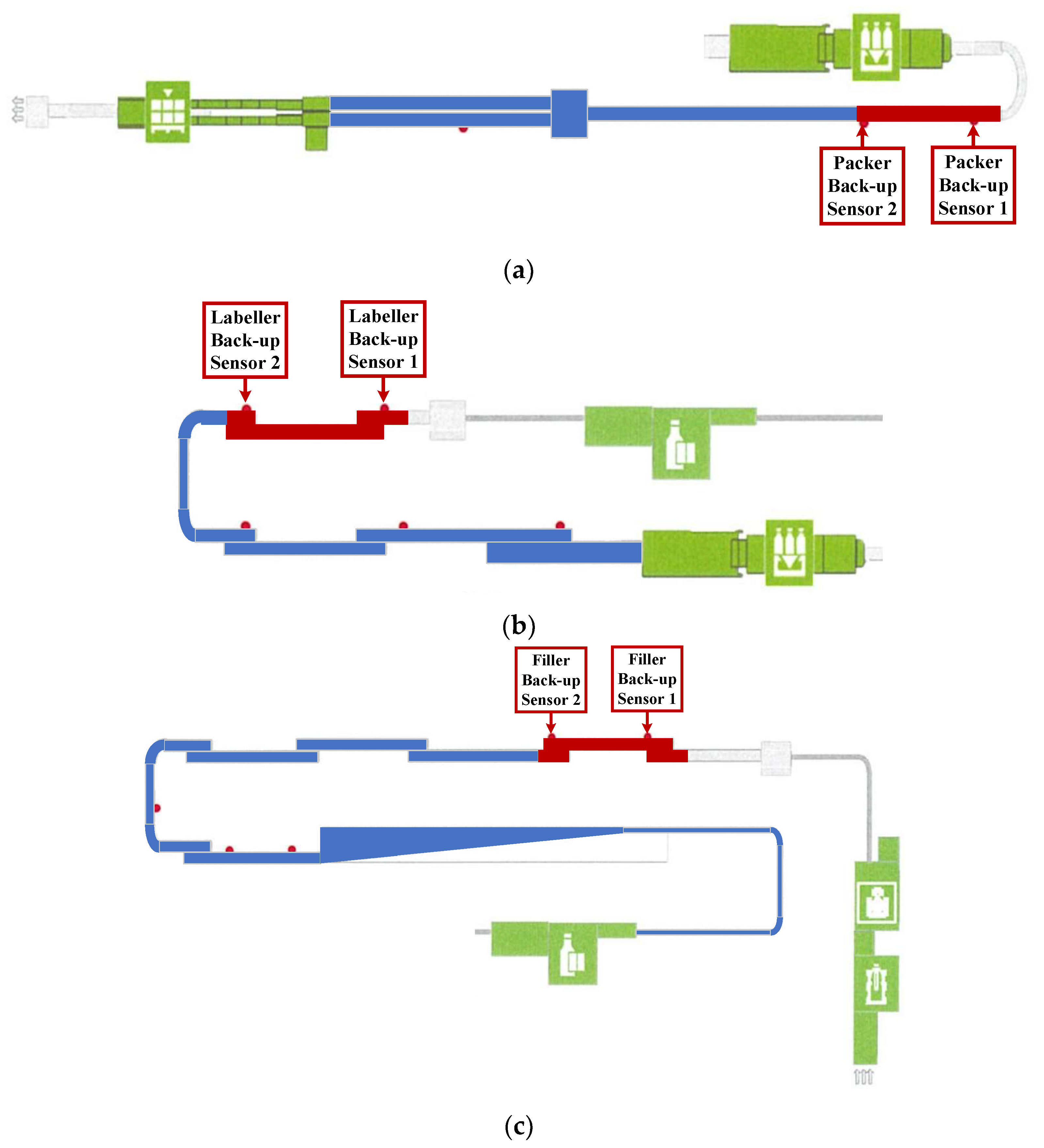
The waiting time for draining the bottles from the conveyor assumes different values for each machine, as listed in Table 3. When one of the machines is stopped, this stoppage affects other machines in the previous process. For example, if the palletizer machine is stopped, the bottles fed from the variopac machine will accumulate in the conveyor between the palletizer machine up to the variopac machine’s backup sensor 1. This results in the stoppage of the variopac, labeller, and filler machines, respectively, as illustrated in Figure 8.
After solving the problem, the machine must be restarted starting from the machine at the end of the production system. In Figure 8a, the palletizer machine must be started to pull the bottle packs in the conveyor out of the system until the packer backup sensor 2 of the variopac machines. This process requires 22 s. Subsequently, the labeller machine is started, as displayed in Figure 8b, and it must wait for 40 s for the variopac machine to operate until the bottles in the conveyor are drained out of the labeller backup sensor 2. Finally, the filler machine is restarted, which requires waiting for 150 s to drain the bottles until the filler backup sensor 2, as indicated in Figure 8c and Table 3.

4. Production System Improvement

The analysis of the production system reveals that if the machine in the system constantly runs at the highest speed and machines in the subsequent process invariably operate at a 10% higher speed, the conveyor will always have free space. The empty space of this conveyor can accommodate bottles at any given time. Therefore, the waiting time required to drain the bottle before starting the machine is no longer necessary. If there is empty space between the backup sensor 1 and the machine, while the machine is set to run at the highest speed, the issue of bottles overflowing the conveyor is completely mitigated, and the system can sustain continued production. The concept of a function that commands the machine to start at its maximum production speed and does not consider the signal from the backup sensor is illustrated in Figure 9. This function is named the ‘Fast Restart Function’.

4.1. Concept of ‘Fast Restart Function’

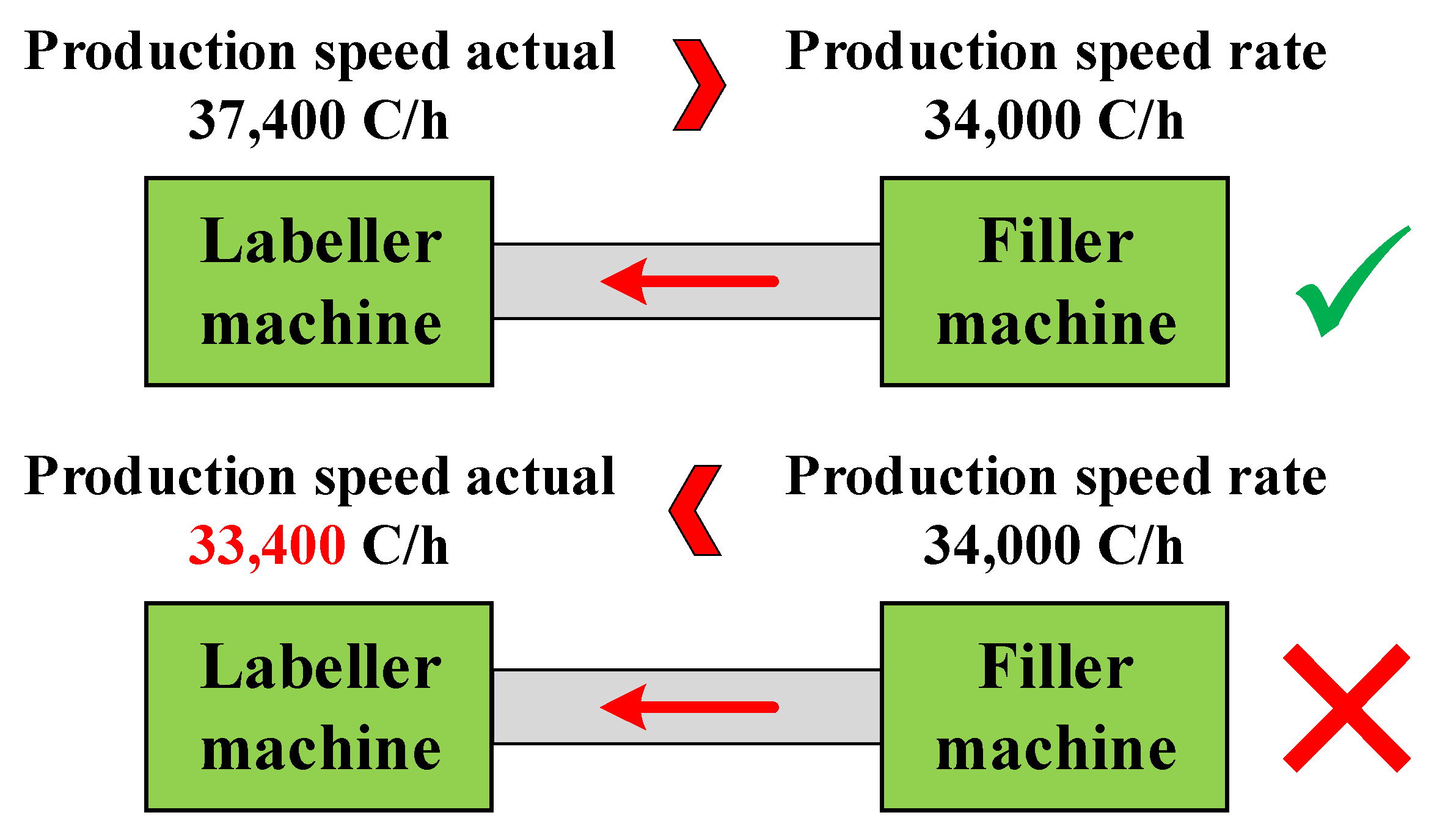
The concept of the fast restart function was developed in the Simatic Manager Step 7 program—a program used in conjunction with the programmable logic controller (PLC). This program is used to process production system operations. The fast restart function is based on the principle of comparing the production speeds between two machines to determine the possibility of continuous operation. As displayed in Figure 10, if the production speed of the filler machine is 34,000 bottles per hour, the labeller machine must ensure production at a speed of more than 34,000 bottles per hour. In the fast restart function, the filler machine can be started by ignoring the signal from the backup sensor. Conversely, if the labeller machine has a production speed same or less than 34,000 bottles per hour, the fast restart function will halt operations immediately. After the fast restart function, all machines will operate at the highest production speed. During the fast restart function, the back-up sensor signal is disregarded to prevent blocking of the restart function. This function will remain in the fast restart function state until the bottle in the conveyor is reduced to a level of back-up sensor 1, then will go into normal working condition. Then the working speed of the labeller machine, variopac machine, and palletizer machine is proportional to the number of bottles accumulated in the belt. These are described in Section 3.2 and Table 2 by slow speed sensor, medium speed sensor, and fast speed sensor of the machinery in the conveyor.
The fast restart function is written in the Simatic Manager Step 7 program as a ladder diagram language including one function block and one data block, as indicated in Figure 11a. The function block is used to control the operation of the fast restart function, while the data block collects the machine’s production speed. In Figure 11b, a data block (DB10) consists of a speed actual machine 2 and a set point machine 1. The function block (FC1) consists of six networks, as demonstrated in Figure 11c.
Network 1 (Speed Actual Machine 2) is employed to obtain the actual production speed of the machine in the next process and store it in the data block (DB10) as a SpeedActualmachine2 variable.
Network 2 (SetPoint Machine 1) is utilized to obtain the maximum start speed of the machine. The values are set via the touch screen monitor, as illustrated in Figure 11d, and stored in the data block (DB10) as the SetPointMachine1 variable.
Network 3 (Comparison of the individual speeds) is the main network of the fast restart function obtained by comparing the machine speeds. When the next process machine attains a speed greater than the maximum starting speed, i.e., theSpeedActualmachine2 is greater than SetPointMachine1, the Q4.0 (Auxiliary marker override active) is flagged as ‘1’. This network can be enabled by the fast restart function and the touch screen, thereby rendering the I0.0 (F_bridging active) to reflect a status of ‘1’.
Network 4 (Delay bridging active) is used to delay the start time of the machine, thereby preventing the bottle overflow problem. The delay time causes the Q4.4 (F_Delay bridging active) to reflect a status of ‘1’, and the fast restart function is terminated at this network. The Q4.4 (F_Delay bridging active) logic can be implemented to start the machine.
Network 5 (Auxiliary filler back-up 1) is utilized for controlling the operation. If the next process machine stops working, more bottles will accumulate in the conveyor. When it reaches the back-up sensor 2 level, the I0.2 (filler back-up 2 active) has a ‘1’ state and the Q4.1 (Auxiliary filler back-up 2) has a ‘1’ state.
Network 6 (power jam in the outlet) is a logic for stopping the machine. When the Q4.5 (power jam in the outlet) status is ‘1’, if the bottle is in the conveyor leading up to the back-up sensor 1 level, the I0.3 (Back-up active 1) has a status of ‘1’ and back-up sensor 2 renders the I0.2 (filler back-up 2 active) status ‘1’. The Q4.4 (F_Delay bridging active) is previously in a ‘normally closed’ state. If the fast restart function is enabled and the Q4.4 (F_Delay bridging active) status is ‘1’, then the Q4.5 (Power jam in the outlet) status is ‘0’; thus, the machine can be started while the bottles continue to accumulate in the conveyor.

4.2. ‘Fast Restart Function’ Performance

An important parameter in this function is the speed of the started machine. This is set at the maximum production speed of each machine. In a 600 mL beverage production system, a production speed of 34,000 bottles per hour is achieved, and the parameter values are listed in Table 4. All machines are assigned a delay time for turning on/off the machine at 1 s. When the machine in the next process has reached its maximum speed of 5 s, the machine that wants to start will require a 1 s start-up delay before starting up. Therefore, the wait time for the fast restart function is 6 s. Notably, compared to the traditional function, the ‘fast restart function can reduce the wait time considerably.
In Table 4, if the variopac machine is stopped, it will have the effect of stopping labeller machine. In a normal restart function, it takes 40 s to drain the bottle from the conveyor. For the fast restart function, there will be no waiting for bottles to drain from the conveyor. As the working speed of the variopac machine is already higher than the labeller machine, the bottle drain time is only 5 s and the starting time is 1 s, so the total waiting time is only 6 s. Therefore, restarting the variopac machine with the fast restart function takes just 6 s instead of 22 s, saving 16 s. Starting the labeller machine takes only 6 s instead of 40 s, which saves 34 s. Restarting the labeller machine takes only 6 s instead of 40 s, which saves 34 s. Finally, restarting the filler machine takes only 6 s instead of 150 s, which also saves 144 s.
However, when considering the waiting time of each machine listed in Table 5, this research analysed the waiting time in three machines: palletizer, variopac machine, and labeller machines. When the palletizer machine stops working, it causes the variopac, labeller, and filler machines to stop working as well. To restore the production system to normal operation using the original function, the waiting time is up to 212 s; however, upon using the fast restart function, it requires a waiting time of 18 s, thereby reducing the waiting time by 194 s. When the variopac machine has ceased working, and the labeller and filler machines have also stopped working, the fast restart function can reduce the waiting time by 178 s. Finally, in the case of the labeller machine stoppage, the filler machine also stops working. The fast restart function requires a waiting time of 6 s and can reduce the waiting time by 144 s. Therefore, the fast restart function considerably reduces the waiting time for restarting machines, while still ensuring their safe operation, thereby resulting in continuous production.
Table 5 shows the performance comparison between the traditional function and the fast restart function in the case of the filler machine failure. A filling machine has 20 downtimes per day typically and a total repair time of 7920 s per day, as listed in Table 6. Each original restart of the filling machine requires 150 s, amounting to 3000 s per day. While restarting the filler machine with the fast restart function takes only 6 s at a time, or 120 s per day. When calculating the total downtime, it was found that the original restart function resulted in a downtime of up to 10,920 s per day, but with the fast restart function, the total downtime was reduced to 8040 s per day. Thus, by reducing the downtime per day, the working time of the machines each day are increased. The fast restart function increased the production efficiency from 86.81% to 90.29% and could produce 705,734 bottles per day, which could increase the original production by 27,187 bottles per day. Therefore, compared to the original restart function, the fast restart function can raise the productivity of the production system by 3.48%.

5. Conclusions

The operation of the machine in the plastic bottle beverage production process requires continuous work and less errors. Often, the slightest mistake can affect the production system, causing machine downtime and leading to reduced productivity. Studying the working principle of the machine in the production process will help to understand the correct working principle, necessary conditions for work, and weaknesses of work processes that should be improved. When examining how the equipment in the process of producing plastic bottled beverages operates, it was found that the machines were stopped many times each day, and solving the problem and restarting the machine takes a long time. As a result, the operating time and efficiency of the machine is reduced. To solve this problem, even after solving the machine downtime problem until the machine can resume normal operation, but restarting the machine is difficult because of the bottles piled on the conveyor. It is necessary to empty off any bottles that have accumulated in the conveyor first, the machine in the previous process can be restarted. In addition, it takes a lot of time to drain the bottles stuck in the conveyor. This directly affects the reduced operating time and efficiency of the machine. Therefore, this study proposes a function to reduce the waiting time for bottle venting accumulated in the machine conveyor, named the ‘Fast Restart Function’. The fast restart function is a function to compare the speed of machines in adjacent processes. This allows the machine in the previous process to be restarted without waiting to drain the accumulated bottles in the conveyor. The fast restart function could reduce the restart time after a failure. The efficiency of the production system increased from 86.81% to 90.29%, and this function could improve the average production capacity by 27,187 bottles/day, i.e., 3.48% of the production capacity per day. The results indicated this strategy’s potential use in inefficient production systems or systems with frequent shutdowns in production systems.

Author Contributions

Conceptualization, C.J. and A.N.; methodology, S.Y.; software, S.T.; validation, S.B.; formal analysis, S.Y.; investigation, N.P.; resources, S.B.; data curation, A.N.; writing—original draft preparation, N.P.; writing—review and editing, N.P.; visualization, S.T.; supervision, C.J. and A.N.; project administration, S.B.; funding acquisition, C.J. All authors have read and agreed to the published version of the manuscript.

Funding

This research was funded by King Mongkut’s Institute of Technology Ladkrabang Research Fund, Thailand, grant number 2564-02-01-016.

Data Availability Statement

No new data were created or analyzed in this study. Data sharing is not applicable to this article.

Acknowledgments

The authors wish to gratefully acknowledge the financial support for this research (No. 2564-02-01-016) from King Mongkut’s Institute of Technology Ladkrabang Research fund, Thailand.

Conflicts of Interest

The authors declare no conflict of interest.

References

  1. Wichailert, K.; Yousapornpaiboon, K. Brand Equity Affects Brand Loyalty of the Bottled Mineral Drinking Water in Thailand. J. Adm. Bus. Stud. 2017, 3, 180–191. [Google Scholar]
  2. Kruawal, K.; Sacher, F.; Werner, A.; Müller, J.; Knepper, T.P. Chemical water quality in Thailand and its impacts on the drinking water production in Thailand. Sci. Total Environ. 2005, 340, 57–70. [Google Scholar] [CrossRef] [PubMed]
  3. Padhee, S.; Nandan, D. Design of Automated Visual Inspection System for Beverage Industry Production Line. Trait. Signal 2021, 38, 461–466. [Google Scholar] [CrossRef]
  4. Jacob, B.; Mohamed, A.O.; Muduli, K. Effect of Preventive Maintenance on Machine Reliability in a Beverage Packaging Plant. Int. J. Syst. Dyn. Appl. 2021, 10, 50–66. [Google Scholar]
  5. De Mattosa, D.L.; Netob, R.A.; Díaz Merinoa, E.A.; Forcellinib, F.A. Simulating the influence of physical overload on assembly line performance: A case study in an automotive electrical component plant. Appl. Ergon. 2019, 79, 107–121. [Google Scholar] [CrossRef] [PubMed]
  6. Gola, A.; Nieoczym, A. Application of OEE Coefficient for Manufacturing Lines Reliability Improvement. Adv. Econ. Bus. Manag. Res. 2017, 31, 189–194. [Google Scholar]
  7. Li, Y.; Chang, Q.; Xiao, G.; Arinez, J. Data-Driven Analysis of Downtime Impacts in Parallel Production Systems. IEEE Trans. Autom. Sci. Eng. 2015, 12, 1541–1547. [Google Scholar] [CrossRef]
  8. Wolniak, R. Downtime in the Automotive Industry Production Process—Cause Analysis. Qual. Innov. Prosper. 2019, 23, 101. [Google Scholar] [CrossRef] [Green Version]
  9. Ashraf, S.R.B.; Rashid, M.M.; Harunur Rashid, A.R.M. Implementation of 5S Methodology in a Food & Beverage Industry: A Case Study. Int. Res. J. Eng. Technol. 2017, 4, 1791–1796. [Google Scholar]
  10. Rajasekar, D.; Sengupta, G. Line feeding downtime reduction by implementing lean material handling techniques in automotive manufacturing. Int. J. Manag. IT Eng. 2020, 10, 39–52. [Google Scholar]
  11. Kumara, P.; Tewarib, P.C. Performance analysis and optimization for CSDGB filling system of a beverage plant using particle swarm optimization. Int. J. Ind. Eng. Comput. 2017, 8, 303–314. [Google Scholar] [CrossRef]
  12. Zou, J.; Chang, Q.; Lei, Y.; Arinez, J. Production System Performance Identification Using Sensor Data. IEEE Trans. Syst. Man Cybern. Syst. 2018, 48, 255–264. [Google Scholar] [CrossRef]
  13. Petchwattana, N.; Naknaen, P.; Jakrabutr, W.; Sanetuntikul, J.; Narupai, B. Modification of Poly (Lactic Acid) by Blending with Poly (Methyl Methacrylate-Co-Ethyl Acrylate) for Extrusion Blow Molding Application. J. Eng. Sci. Technol. 2017, 12, 2766–2777. [Google Scholar]
  14. Biglione, J.; Béreaux, Y.; Charmeau, J.-Y.; Balcaen, J.; Chhay, S. Numerical simulation and optimization of the injection blow molding of polypropylene bottles—A single stage process. Int. J. Mater. Form. 2016, 9, 471–487. [Google Scholar] [CrossRef]
  15. Hsieh, Y.-C.; Doan, M.H. Research on both the radiation heating and the cooling system inside the stretch blow molding machine CPSB-LSS12. Int. J. Adv. Manuf. Technol. 2018, 98, 2357–2364. [Google Scholar] [CrossRef]
  16. Kalidasan, B.; Ben Ajai Raja, J.; Giri Gowtham, M.; Kadeesh, M. Automatic Bottle Filling Machine. Int. Res. J. Eng. Technol. 2018, 5, 407–408. [Google Scholar]
  17. Nwadinobi, C.P.; Mejeh, K.I.; Eti, P.E. Development of Network Model for Overhaul Maintenance of Meyer 78/18 Bottle Filling Machine. Int. J. Eng. Mod. Technol. 2017, 3, 8–21. [Google Scholar]
  18. Sawai Ben, J. Implementation of Autonomous Maintenance and its Effect on MTBF, MTTR, and Reliability of a Critical Machine in a Beer Processing Plant. Int. J. Progress. Sci. Technol. 2022, 31, 57–66. [Google Scholar]
  19. Ben, J.; Mohamed, A.; Muduli, K. Optimizing Bottle Washer Performance in Cleaning Returnable Glass Bottles for Reuse in Beverage Packaging. Int. J. Adv. Sci. Technol. 2020, 29, 8149–8159. [Google Scholar]
Figure 1. The plastic bottled-beverage production system: (a) Model of the plastic bottled-beverage production system; (b) Flowchart of the plastic bottled beverage production system.
Processes 11 00039 g001
Figure 2. Sensor position in the beverage production system.
Processes 11 00039 g002
Figure 3. Conditions for starting the machine: (a) In the case that raw materials are ready for production and no bottles accumulate in the conveyor; (b) In the case that raw materials are ready for production and bottles are collected in the conveyor.
Processes 11 00039 g003
Figure 4. Conditions for stopping the machine: (a) Bottles have accumulated in the conveyor with a large volume up to the back-up machine sensor 1; (b) Bottles accumulated in the belt are larger than the back-up machine sensor 1.
Processes 11 00039 g004
Figure 5. Conditions for controlling the machine to ensure a high production speed.
Processes 11 00039 g005
Figure 6. Conditions for controlling the machine to ensure a medium production speed: (a) Conditions for controlling the machine to ensure a medium production speed in case 1; (b) Conditions for controlling the machine to ensure a medium production speed in case 2; (c) Conditions for controlling the machine to ensure a medium production speed in case 3.
Processes 11 00039 g006
Figure 7. Conditions for controlling the machine to ensure a low production speed: (a) Conditions for controlling the machine to ensure a low production speed in case 1; (b) Conditions for controlling the machine to ensure a low production speed in case 2.
Processes 11 00039 g007
Figure 8. Area showing the amount of bottles accumulated in the conveyor upon system failure; the red area denotes the area occupied by the bottles in the conveyor that is greater than the backup sensor 2, and the blue area depicts the area occupied by the bottles in the conveyor: (a) Bottle area accumulated in the conveyor between the variopac machine and the palletizer machine; (b) Bottle area accumulated in the conveyor between the labeller machine and the variopac machine; (c) Bottle area accumulated in the conveyor between the filler machine and the labeller machine.
Processes 11 00039 g008
Figure 9. Concept of ‘Fast Restart Function’.
Processes 11 00039 g009
Figure 10. Sensor position of each machine.
Processes 11 00039 g010
Figure 11. ‘Fast Restart Function’: (a) Fast restart block; (b) Data block (DB10); (c) Fast restart operator; (d) Touch screen monitor.
Processes 11 00039 g011aProcesses 11 00039 g011b
Table 1. Working speed of each machine.
MachineAdjust SpeedSpeed
(Bottles/Hour)
Speed
(Percentage)
Blow moulding machineConstant speed34,000100
Filler machineConstant speed34,000100
Labeller machineAdjustable speed37,400110
Variopac machineAdjustable speed40,800120
Palletizer machineAdjustable speed44,200130
Table 2. Production speed control with sensor status.
Machine StatusProduction SpeedBack-Up Sensor 2Back-Up Sensor 1Slow Speed SensorMedium Speed SensorFast Speed SensorFigure
Match
RunFastONONOFFOFFOFF5
MediumOFFONOFFOFFOFF6 (a)
MediumOFFONOFFOFFON6 (b)
MediumONONOFFOFFON6 (c)
SlowOFFONOFFONON7 (a)
SlowONONOFFONON7 (b)
Stop-OFFOFFN/CN/CN/C4
Table 3. Waiting time of each machine for transporting the bottles from the conveyor until the back-up sensor 2.
MachineTime (s)Figure Match
Variopac machine228 (c)
Labeller machine408 (b)
Filler machine1508 (a)
Table 4. Wait time reduction when using the ‘Fast Restart Function’.
Started MachineNext MachineWaiting for Start (s)Reduced Time
(s)
OriginalFast Restart
Variopac machinePalletizer machine22616
Labeller machineVariopac machine40634
Filler machineLabeller machine1506144
Table 5. Comparison of the waiting time for filler machine starting when each machine stopped.
Stopped Working MachineWaiting Time (s)Reduced Time (s)
OriginalFast Restart
Palletizer machine21218194
Variopac machine19012178
Labeller machine1506144
Table 6. Performance comparison between original function and ‘Fast Restart Function’ of filler machine.
TopicsOriginalFast RestartUnit
Average system malfunction2020times/day
Average system fix time79207920seconds/day
Average starting time (per time)1506seconds/time
Average starting time (per day)3000120seconds/day
Total downtime10,9208040seconds/day
Average system operating time71,88074,760seconds/day
Average number of bottles produced678,547705,734bottles/day
System performance86.8190.29percent
Disclaimer/Publisher’s Note: The statements, opinions and data contained in all publications are solely those of the individual author(s) and contributor(s) and not of MDPI and/or the editor(s). MDPI and/or the editor(s) disclaim responsibility for any injury to people or property resulting from any ideas, methods, instructions or products referred to in the content.