Article

Numerical Simulations of Particle Motions at Continuous Rotational Speed Changes in Horizontal Rotating Drums

1
School of Energy and Power Engineering, Northeast Electric Power University, Jilin 132012, China
2
Engineering Research Centre of Oil Shale Comprehensive Utilization, Ministry of Education, Northeast Electric Power University, Jilin 132012, China
3
Huaneng Chaohu Power Generation Co., Ltd., Chaohu 238015, China
*
Author to whom correspondence should be addressed.
Processes 2023, 11(1), 47; https://doi.org/10.3390/pr11010047
Submission received: 11 November 2022 / Revised: 16 December 2022 / Accepted: 20 December 2022 / Published: 25 December 2022
(This article belongs to the Section Chemical Processes and Systems)

Abstract

:
The motion of binary particles in three horizontal rotating drums with continuous rotational speed changes was studied based on the Discrete Element Method (DEM). Different simulation conditions were compared between two circular drums and an elliptical drum using the same number of physical properties for binary particles and drums, rotating at a speed series from 0.01 to 21.9 rad/s. By varying the rotational speed, four flow regimes were produced in the simulation. Flow regimes, velocity vectors, normal forces, and the number of contacts between 1 mm particles and 3 mm particles were comparatively analyzed, especially the particle velocity at transient changing rotational speeds. The results showed that four flow regimes were found at the same rotational speed for three different rotating drums, and normal forces were weakest for the cataracting regime; moreover, the three layers of particles were damaged when the rotational speed was suddenly decreased and the velocity direction of the particle motion was changed at the top of the particles’ bed. The maximum number of contacts was found with the rolling regime, based on the simulation results. The number of contacts of the major axis circular drum was smaller than for the minor axis at the same rotational speed, and the number of contacts of the elliptical drum was the largest among the three rotating drums.

1. Introduction

Horizontal rotating drums have many industrial applications, such as cement kilns [1], mixing machines [2,3], pyrolysis furnaces [4]. Research on the efficient mixing of drums can help reduce energy waste and contribute to carbon neutrality targets [5]. Based on the rotational speed and physical properties of particles, six flow regimes have been identified, including slipping, slumping, rolling, cascading, cataracting, and centrifuging [6,7].
Different particle shapes and parameters will affect its motion and the mixing process in the roller. Zhang et al. [8]. studied the average velocity changes in a mixed particle system with 3 mm rectangular particles (RP), triangular particles (TP), and circular particles (CP), and 1 mm spherical particles in an elliptical drum at different rotational speeds; they found that with the increase in the eccentricity of the drum the average velocity fluctuation range of the flake particle system increases gradually. Mellmann [9] plotted bed behavior diagrams of the transverse motions of different particle materials in a rotating drum and analyzed the effects of operating variables, structural parameters of the rotating drums, and the physical properties of particles in flow regimes. Huang et al. [10] used molecular dynamics to simulate binary particle segregation in the radial direction of a high-velocity rotating drum and reported the effects of the radius and density of the particles. Arntz et al. [11] used DEM to study the segregation of granular particles in a horizontal rotating drum, occurring at the rolling, cascading, cataracting, and centrifuging regimes. Ding et al. used a non-invasive positron emission particle tracking (PEPT) technique to investigate the rolling mode [12,13] and slumping mode [14] in a binary mixture. The rolling regime has been investigated in the literature. Santomaso et al. observed the poorly mixed core at low rotational speeds in the rolling regime [15] and compared the mixing efficiency between rolling and cataracting [16]. Santos et al. [17] used the Euler approach to analyze the hydrodynamic behavior in a rotating drum in the rolling regime. The horizontal rotating ellipsoidal drum was simulated by Dan et al. [18,19] and Ayeni et al. [20]. Liao et al. [21] studied the density segregation of wet granular mixtures in a rotating drum by experiment. In this study, particle segregation was enhanced at a high rotational speed.
Different flow regimes could be observed at different rotational speeds of the drum, particle densities [22,23], and filling degrees [24]. Most studies on segregation have focused on different regimes at different rotational speeds; however, the rotational speeds are only one of several key factors. When the rotational speed has been suddenly changed, the flow regimes of particles in the rotating drum that are differential were not well-considered.
In this study, the following topics will be discussed to take into account the influence of continuously changing rotational speeds of rotary drums on the particles moving and the number of contacts between binary particles. The main contributions of this work are summarized below:
(1)
An integrated view of the motion properties of binary particles in the rotating drums is made. Key characteristics of flow regimes and normal forces are analyzed and compared with two circular rotating drums and one elliptical drum, in order to provide further insight into the constant stream of changing rotational speeds;
(2)
Three independent particle motion characteristics: transient state, steady state, and the sudden change in states are investigated when the rotational speed is changed continuously.

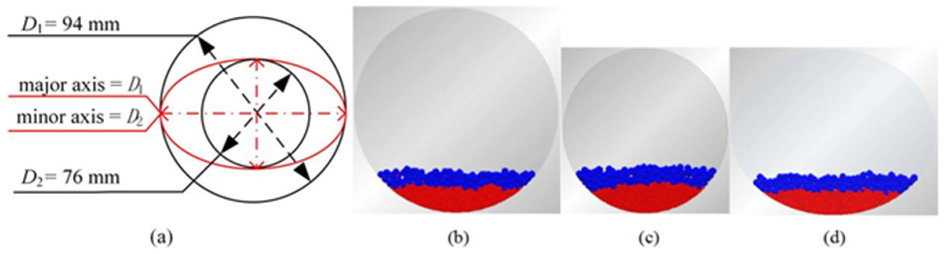
2. Materials and Methods

Simulations were carried out in an elliptical drum and two circular drums. The major axis of the elliptical drum is D1 = 94 mm and the minor axis is D2 = 76 mm. The diameter of the circular drums is D1 = 94 mm, which is the same as the major axis of the elliptical drum. The diameter of another circular drum is D2 = 76 mm, which equals the minor axis of the elliptical drum, as illustrated in Figure 1a. The width of all three drums is 8 mm. There are two types of particles in the drum, the red particles with 1 mm diameter were at the bottom of the rotating drums and the blue ones with 3 mm diameter were located in the upper layer. As shown in Figure 1b–d, two layers were observed in the initial state of binary particles in the rotating drums; ω is the rotational speed of the rotating drums.
In order to make the particles in the drums go through different flow regimes, the rotational speed of the drums is continuously changed, as shown in Figure 2. The drum starts the operation in 0.5 s and the rotational speed of the drum maintains at 3.14 rad/s from 0.5 to 25 s in order to make the drums reach steady state. From 25 to 100 s, the rotational speed of the drums experienced various changes, including slow and quick accelerations and decelerations. The maximum speed of the drums can make the particles within the drums reach the centrifuging regime.
The commercial package EDEM (EDEM 2.7, DEM solutions) was used. The DEM is based on Newton’s second law and models the dynamics of each particle separately. For each mass i, there are two types of motion, translational and rotational, which can be described as:
m i a = j ( F n + F t + m i g )
I i θ = j ( R J + F t μ r R i | F n | ω ^ )
where m i , a , I i , and θ are the mass, linear acceleration, moment of inertia, and angular acceleration of the particle i, respectively; F n and F t are the normal contact force and tangential contact force, respectively; R J is the vector from the center of the particle to the point of contact; μ r is the coefficient of rolling friction; g is the acceleration of gravity.
It treated particles as soft spheres based on the overall particle–particle interaction following the Hertz–Mindlin model in which the contact mechanics can be considered. The Hertz–Mindlin mode (without slip) used in this paper is the default model of the EDEM software and is accurate and efficient in the calculation of forces. In this model, the discovery and tangential components are based on the Hertzian contact theory and the work of Middlin–Deresiewicz, respectively [25]. Parameters of the simulated systems are listed in Table 1.

3. Results and Discussion

The results of the three-dimensional simulations were analyzed including flow regimes, normal force, and the number of contacts. In particular, the number of contacts was influenced by different rotational speeds [26]. The impact of complex rotational speed variations on the number of contacts and velocity probability density of 3 mm particles has been studied in detail as follows.

3.1. Moving Particles at Different Rotational Speeds
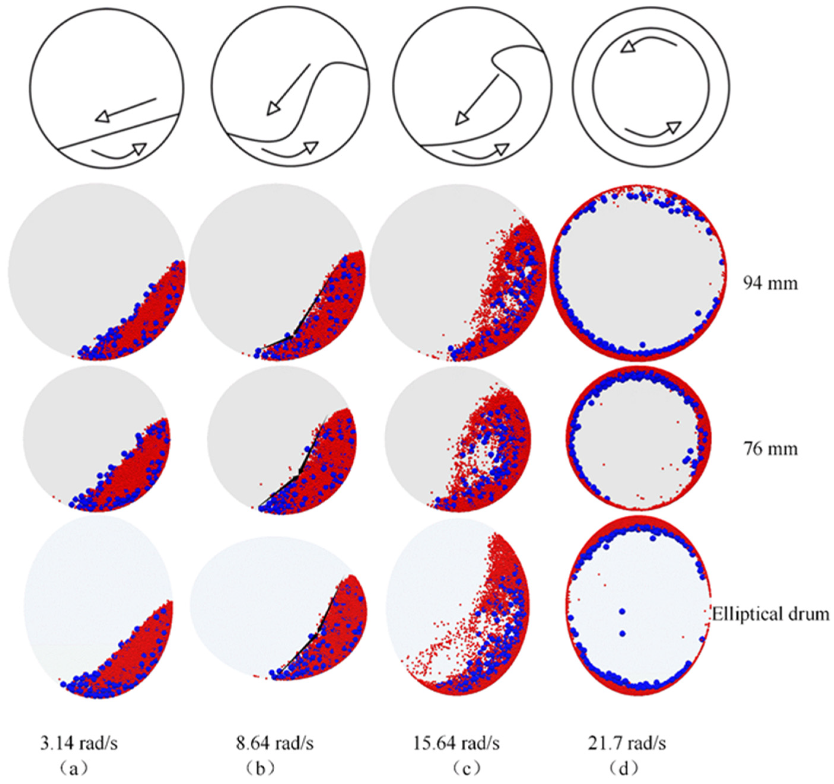
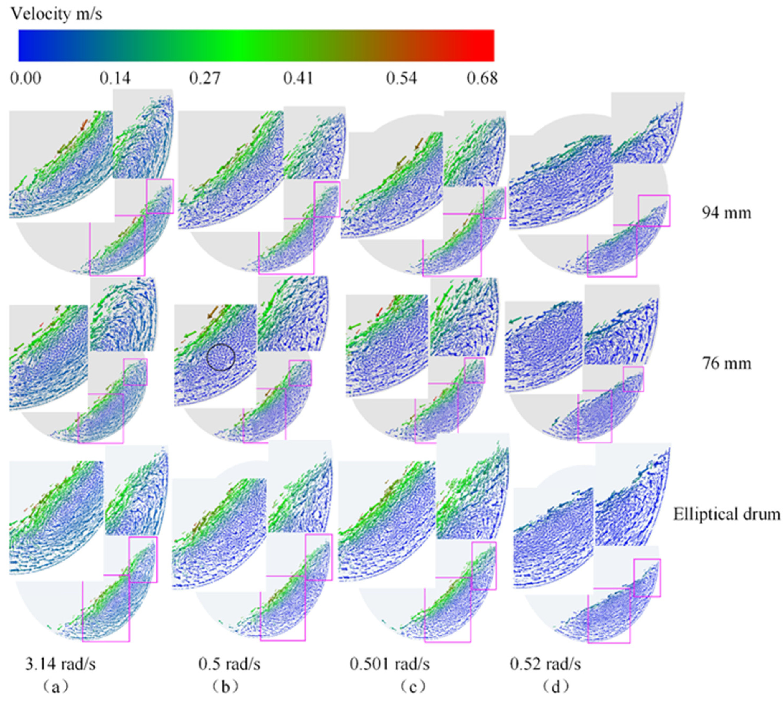
3.1.1. Flow Regimes

The flow regime is related to the Froude number (Fr), filling degree, and wall friction coefficient 8, which can be expressed as Equation (1). Fr is used to define the ratio of the centrifugal force to gravity ( g ) and to represent the motion of particles in rotating drums 8,17,18.
F r = ω 2 · D / 2 · g
where ω and D are the rotation speed and diameter of the drum, respectively.
The four different regimes of the particle bed motion could be obtained by changing the rotational speed as shown in Figure 3. Owing to the simulations of three different drums with the same number of particles, the filling degrees were not in conformity. It should be noted that the slipping and slumping regime was not observed in the present work.
In Figure 3, radial segregation is observed and smaller particles are in the core of the rolling regime. As a transitional stage, the racial separation phenomenon is not obvious in the cascading regime. In the cataracting regime, more 3 mm particles exist in the core than 1 mm particles. Binary particles spin in ringlike segregation patterns in the radial direction, as was shown in the high-velocity rotating drum 9, including bigger particles or smaller particles within the inner ring on the basis of the different densities of the particles and their sizes. The smaller particles accumulated on the wall of the circular drum; the same phenomenon was also observed in the elliptical drum.
This illustrates that as the rotational speed increases, bigger particles draw near the core of the binary particle system in the rotating drum. For binary particle systems with equal density and different sizes, radial segregation (the bigger or smaller particles in the core) depends on the rotational speed.

3.1.2. Normal Force

The normal force between two adjacent particles is in direct contact. The force network is composed of over three or more normal forces; so the normal force is obviously as important as other contact forces directly related to the force network [27]. Visual observation of the normal force is presented in Figure 4. Three colors are used to display different particles: red is shown among 1 mm particles; green is shown among 3 mm particles; blue is shown between 1 mm and 3 mm particles. In this figure, each rod represents one connection between two particles, and the degree of thickness represents the magnitude of the normal force.
By increasing the rotational speed, the flow regime transforms from the rolling state to the cataracting state; the normal forces among particles gradually decrease, as shown in Figure 4a–c. However, the normal forces strengthen again in the centrifuging regime, as depicted in Figure 4d. For the rolling regime, the wall region of the D2 drum has the maximum forces to occur among 3 mm particles, whereas the wall region of the D1 drum has the minimum forces. A similar phenomenon exists among 1 mm particles. The results indicate that gravity is a key factor, which affects the force in the rolling regime. Under the same conditions, particles are densest in the D2 drum. Strong interaction forces occur between particles. In the cascading and cataracting regimes, the normal forces of drums become gradually weak. In particular, most of the particles were thrown out during the cataracting regime when the normal forces were reduced. In the centrifuging regime, the centrifugal force is directly proportional to the diameter at the same rotational speed according to Equation (2), large forces occur along the wall region of the D1 drum, and an obvious layered structure was found. Consequently, normal forces vary reversely between the rolling regime and the centrifuging regimes.
f = m · ω 2 · D / 2
where f is centrifugal force of particles, m is mass of particles, and D is diameter of rotating drum.

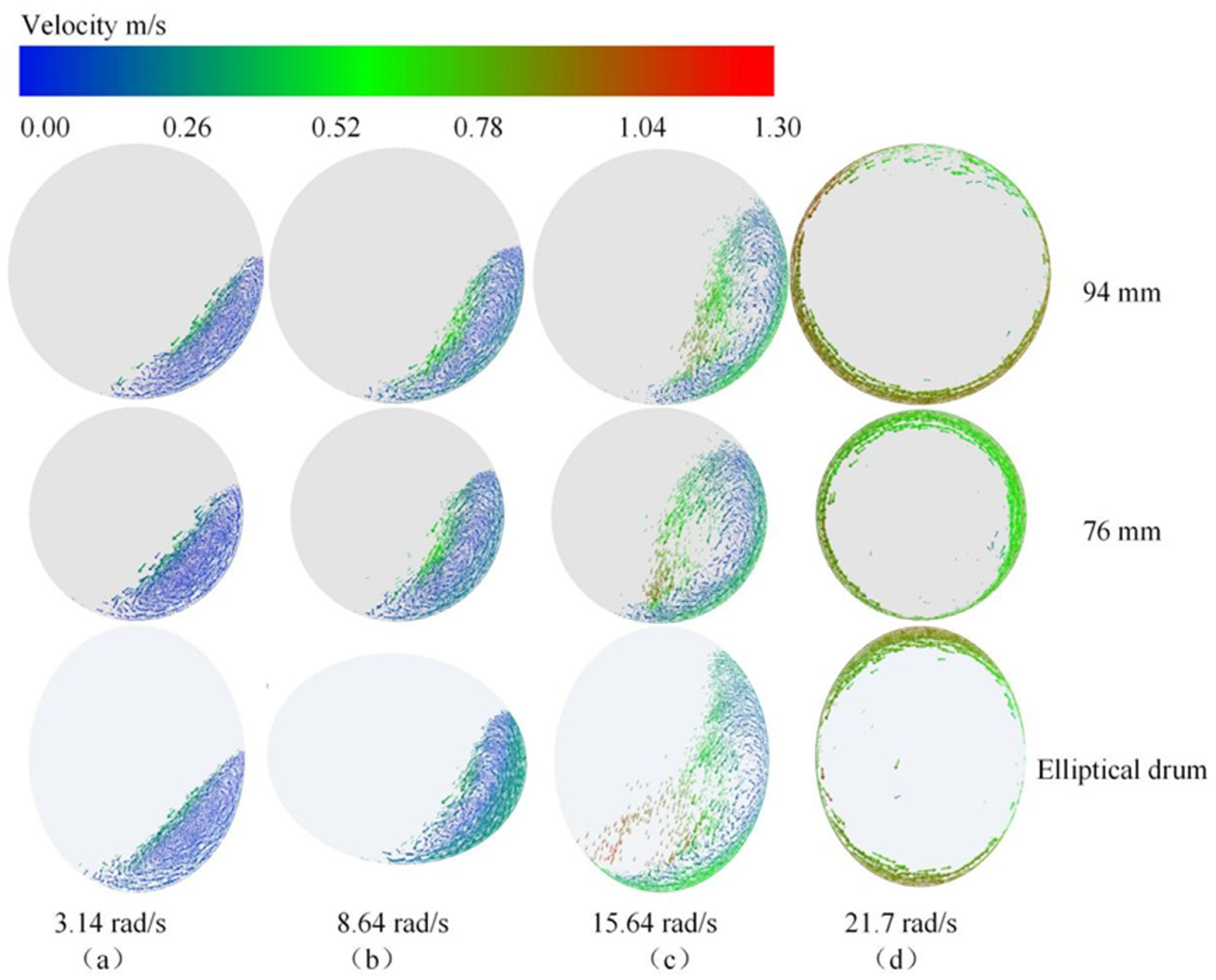
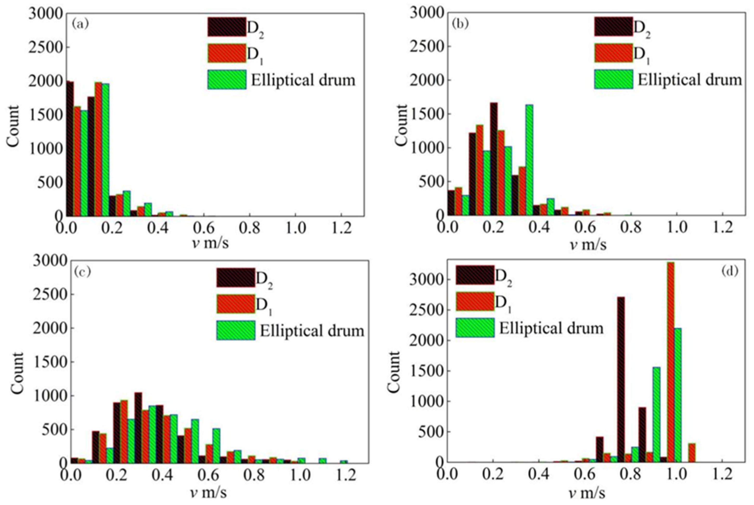
3.1.3. Particle Velocities at Different Rotational Speeds

Figure 5 shows the comparison between the particle velocities within three rotating drums at rotational speeds of 3.14, 8.64, 15.64, and 21.7 rad/s. The velocity of 1 mm and 3 mm particles is observed from one axial slice.
In the 3.14 rad/s case (see Figure 5a), the particle velocity appears as three layers for the three rotating drums: slower particles at the center of the particle system, faster particles along the wall, and the fastest particles at the free surface of the particle flow. This behavior caused by the rolling regime can also be found in [28]. It was also recognized that the free surfaces of three rotating drums approximate a straight line. Figure 5b shows the velocity vectors at 8.64 rad/s and three layers of particle velocities are obvious. A point of inflexion was seen on the free surface of the particle flow. This feature is characteristic of the cascading regime. Figure 5c shows the velocity vector at 15.64 rad/s, particles are thrown off into the free space of the drum 8. In addition, the fastest particles accumulate close to the top region [29], while slower particles are at the center of the particle system. In Figure 5d with a drum speed of 21.7 rad/s, the fastest particles occur along the wall of the three drums and the particle velocity value within the D2 drum is the smallest. In addition, the top point of the particle system continues to rise, changing from a rolling regime to a cataracting regime.
Figure 6 shows the number of particle velocities at different rotational speeds of the three rotating drums. The number of bins of particle velocities is 14. The color identifies the different rotational drums. Black represents the count of the D2 drum, red is the count of the D1 drum, and green is the count of the elliptical drum.
In the 3.14 rad/s case (see Figure 6a), the majority range of the particle velocities is from 0 m/s to 0.2 m/s; the maximum count is close to 2000. The magnitude of the particle velocity varies in the widest range for the rotational speed 15.64 rad/s, from 0 m/s to 1.3 m/s, as shown in Figure 6c. The number of the counts is similar for three rotating drums. Figure 6d shows the particle velocity of the centrifuging regime is 0.8 m/s. The number of particles in the D2 drum is 2700, the velocity of which is about 0.75 m/s; there are above 3000 in the D1 drum, of which the velocity is about 1 m/s. However, the count is rising gradually from 0.8 to 1.0 m/s for the elliptical drum and the maximum count is lower than for the circular drums.

3.2. Transient Analysis of the Drums

In order to observe the details in the transient changing regime of the rotational speeds, the core of the particles and the top of the particle system are zoomed for three drums, as depicted in Figure 7. Because the rotational speed changes suddenly from 3.14 rad/s (Figure 7a) to 0.5 rad/s (Figure 7b), the particle velocities along the wall decrease suddenly. The value of the velocity equals the velocity of the core of the particle system. Two layers form in the particle system, faster particles at the free surface of the particle flow, and others are slower particles. At the top of the particle system, the direction of particle velocity along the wall changes suddenly. The particle velocity shows disorganized particles, except for particles at the free surface flow. As shown in Figure 7d, the area of the core of the particle system was slightly larger than at 3.14 rad/s. Through the whole process of changing rotational speeds, the size of the particles interspersed with one another in the particle system because the rotational speed decreased suddenly.
Figure 8 displays the probability density of the particle velocity for three rotating drums. It can be observed from this figure that the peaks of the probability density become wider as the rotational speed of the drums decreases from 3.14 rad/s to 0.5 rad/s. The peaks gradually become more narrow as the rotational speeds of the drums decrease from 0.5 rad/s to 0.52 rad/s. There is a strong peak in the probabilities of the particle velocity at 3.14 rad/s of D1, D2, and elliptical drums, approximately 12, 21, and 16, respectively. The peak values of the probability density for the particle velocity are close to about 0.025 m/s.

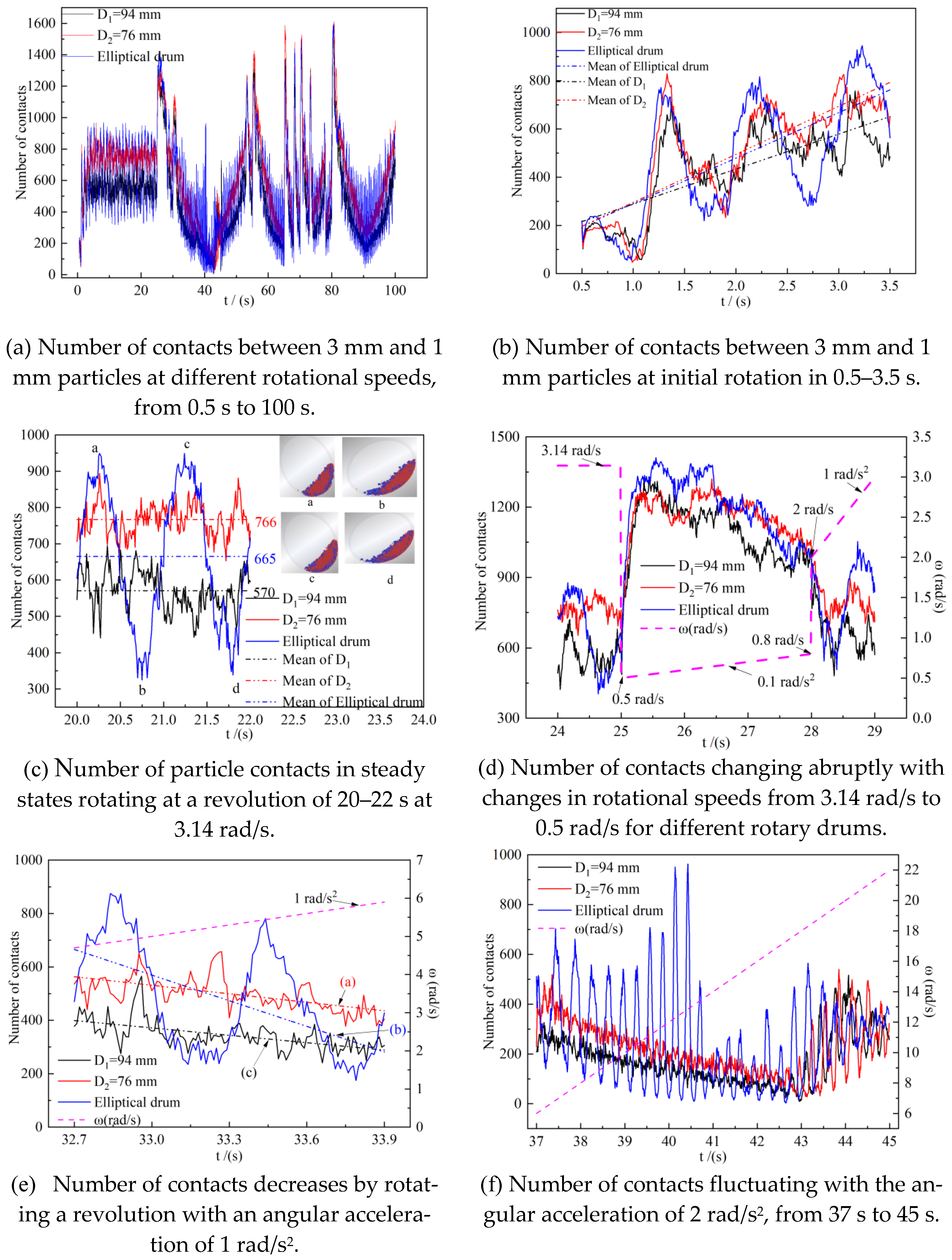
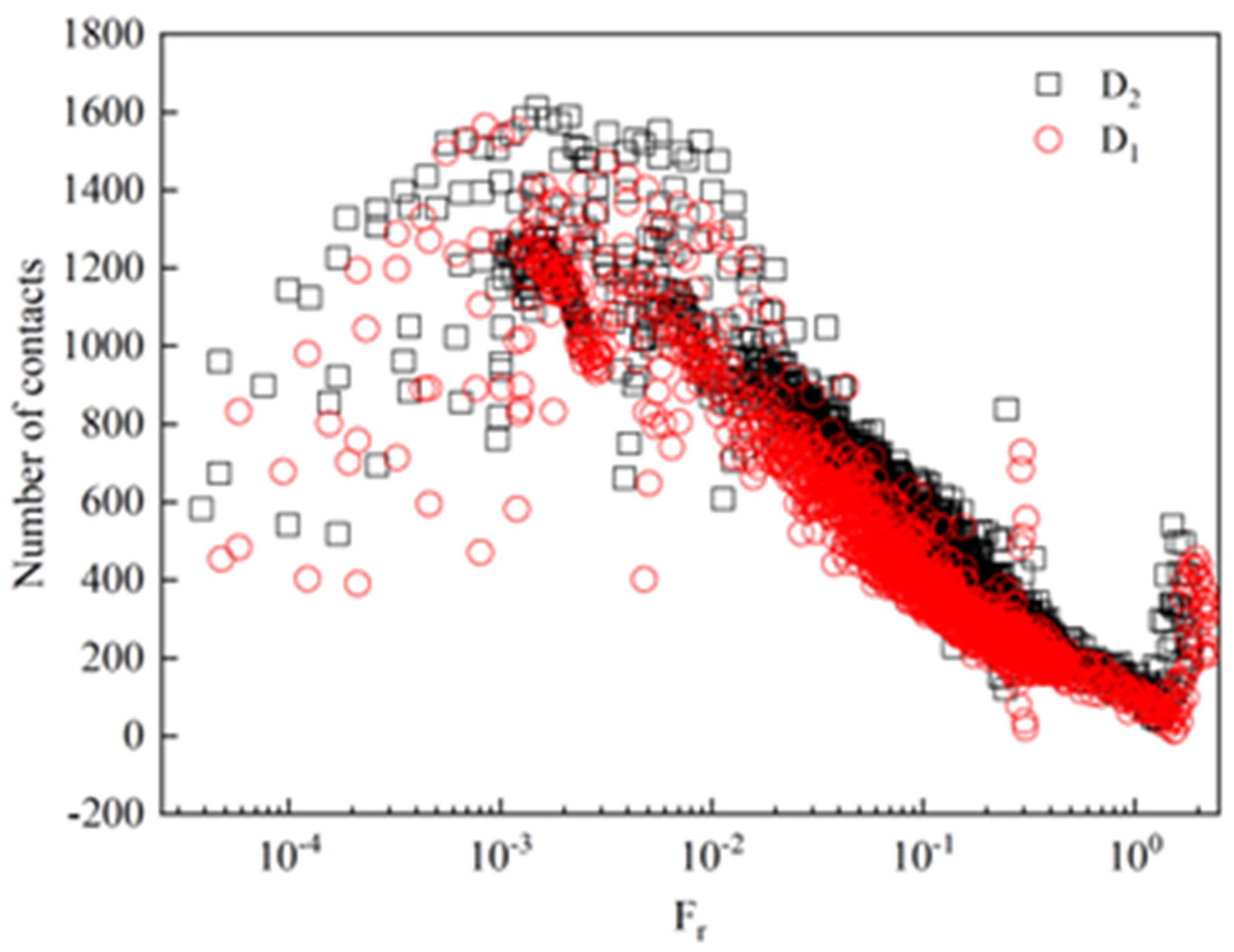
3.3. Number of Contacts

Different numbers of particle contact points are directly linked to heat transfer by conductance [30]. The changes in the number of contacts are between 3 mm particles and 1 mm particles, as shown in Figure 9. Panel (a) illustrates that the different particles’ contact number changes from 0.5 to 100 s through all kinds of rotational speeds, as shown in Figure 2. Detailed analyses from panel (b) to panel (f) were conducted, with different periods of time. Panel (a) illustrates that the number of contacts for D1 is always greater than for D2 and there are no obvious differences in amplitude. The amplitudes for the elliptical drum cover those of the circular drums of diameters D1 and D2. Nevertheless, the results are almost completely contrary to the rotational speed, as shown in Figure 2.
The drums rotate at the constant speed of 3.14 rad/s that starts at 0.5 s (Figure 9b) and the three drums rotate for three seconds, turning one-and-a-half circles. The number of events for the contact with the different drums increases, Figure 9c shows the number of contacts and their mean at a uniform rotational speed, approximately, in one cycle at a lone time of 20 s after inception. This period was more obvious for the elliptical number of contacts in the circle. As a whole, the mean number of contacts in the D2, elliptical, and D1 drums are 766, 665, and 570, respectively.
Figure 9d shows, for changing rotation speed dashed in panel (d), that the number of contacts reads accordingly. The process suddenly drops from a uniform rotation of 3.14 rad/s to 0.5 rad/s and then turns to 0.1 rad/s2 rotational acceleration. After three more seconds at 28 s, the speed then changes abruptly from 0.8 rad/s to 2 rad/s and rotates at the 1 rad/s2 rotational acceleration. The drum accelerates at 0.1 rad/s2 in the interval of 25–28 s. The number of contacts for the three drums has the same trend; the elliptical drum does not have periods such as those shown in Figure 9c at the lower rotation speed. The number of contacts of the three drums was approximately equal at 25 s and 28 s, followed by a gradual separation. At 25 s, because the speed suddenly drops, the number of contacts increases abruptly; when at 28 s, the number of contacts also mutates when the drums go through a sudden high speed.
Figure 9e shows, for an acceleration of 1 rad/s2, the number of contacts changes. As the drum rotates, the circular drums D1 and D2 have nearly the same declining trend. However, the elliptical drum has a larger descending slope than D1 and D2. In Table 2, trend lines were fitted and the slope of the elliptical drum was about three times that of the circular drums.
Linear fitting the number of contacts and time, such as y = m · t + n , m is sloped, and “-”, in contrast to the angular acceleration, is the mean deceleration.
Figure 9f shows that for the high rotating speed with 2 rad/s2 rotational acceleration, the number of contacts changes from 37 s to 45 s, and the flow regimes transfer from cataracting to centrifuging. The number of contacts dropped slightly, followed by increasing the rotational speed. At 42.5 s, the flow regime of the drums was centrifuging; at the same time, the number of contacts of the two circular drums are close to one another. A steady increase in the number of contacts, developed in parallel with the centrifuging. The number of contacts changes for the elliptical drum was more complicated than for the circular drums, the number of contacts of the elliptical drum slow down, then, the maximum is larger than D2′s, and the rotational speed of the drum is from 6 rad/s to 11 rad/s. As the rotational speed continues to rise to 13 rad/s, the maximum number of contacts has greater growth than at 11 rad/s. Due to the continuous changing of the major and minor axes of the elliptical drum, a quarter of the elliptical arc plays a key role in carrying particles and scattering the particles within the elliptical drum. The cataracting flow regime of the elliptical drum is better manifested than for the circular drums, as shown in Figure 3c.
With the further increase in the rotational speed from 13 rad/s up to 22 rad/s, the Brazil nut effect was observed [31]; 1 mm particles move toward the drum wall and 3 mm particles accumulate at the center of the drum 9. The reason is that 1 mm particles easily diffuse into the wall zone through gaps between particles when the three drums rotate at high-speed. So, as the 3 mm particles accumulate at the center of rotation, different particles segregate, and the number of contacts decreases. This phenomenon can be explained by combined percolation and buoyancy effects [32].
However, the major and minor axes of the elliptical drum alternate changes, and the Fr is not constant in a period of rotation. Furthermore, the number of contacts of two circular drums is related to Fr, as shown in Figure 10. As the maximum value of the number of contacts is above 1600, Fr is about 10−3, accordingly, and the regions conform to the rolling regime, the simulation results are the same as 8. The number of contacts reduces gradually as Fr increases, the minimum value of the number of contacts is correspondingly around zero, and Fr is about 1.3. After that, the number of contacts increases with the growth of Fr. On the whole, the number of contacts of D2 drums is larger than that of D1.
From Figure 11, we infer that the number of contacts increases, first, for the three drums along the increasing rotational speed, with the maximum value appearing around 0.5 rad/s. The number of contacts decreased in the form of an index between 0.5 rad/s and 8 rad/s for the two circular drums, with a linear downward trend from 8 rad/s to 18 rad/s; the minimum value appears at 18 rad/s. However, the number of contacts of the elliptical drum has a wider range as the rotational speed increases, accounting for particles moving alternatively parallel to the major axis and the minor axis. Particularly, the rotational speed is the most obvious between 10 rad/s and 14 rad/s.

4. Conclusions

This numerical study using DEM has been performed on the motion of binary particles within three rotating drums at continuously changing rotational speeds. Four different regimes of particle bed motion, namely rolling, cascading, cataracting, and centrifuging are obtained by changing the rotational speed. It is shown that the mixing of particles is improved at the rolling and cascading regime, and the segregation of particles can be found at the cataracting regime and centrifuging regime. Based on the DEM data, it can be seen that the motion of particles of transient characteristics is related to the variation in rotational speed, including both the velocity vector and particle velocity probability density. The number of contacts changes indicate that the rolling regime exhibits the maximum number of contacts and decreases as the rotational speed increases. Moreover, the minimum number of contacts is observed in the transitory stage from the cataracting regime to the centrifuging regime. This behavior is to be expected.

Author Contributions

Conceptualization, Y.Z. and L.Z.; methodology, L.Z.; software, W.L.; validation, Y.Z. and W.L.; formal analysis, Y.Z.; data curation, Y.Z. and W.L.; writing—original draft preparation, Y.Z.; writing—review and editing, Y.Z. and C.S.; supervision, L.Z., Q.W. and H.Q.; funding acquisition, H.Q. All authors have read and agreed to the published version of the manuscript.

Funding

This work was supported by the Jilin Science and Technology Development Plan Project (20200403162SF).

Data Availability Statement

Not applicable.

Conflicts of Interest

The authors declare no conflict of interest.

References

  1. Güereca, L.P.; Torres, N.; Juárez-López, C.R. The co-processing of municipal waste in a cement kiln in Mexico. A life-cycle assessment approach. J. Clean. Prod. 2015, 107, 741–748. [Google Scholar] [CrossRef]
  2. Basinskas, G.; Sakai, M. Numerical study of the mixing efficiency of a ribbon mixer using the discrete element method. Powder Technol. 2016, 287, 380–394. [Google Scholar] [CrossRef]
  3. Gao, W.; Liu, L.; Liao, Z.; Chen, S.; Zang, M.; Tan, Y. Discrete element analysis of the particle mixing performance in a ribbon mixer with a double U-shaped vessel. Granul. Matter 2019, 21, 1–16. [Google Scholar] [CrossRef]
  4. Zhang, L.; Li, Y.; Zhang, H.; Xu, X.; Yang, Z.; Xu, W. A Review of the Potential of District Heating System in Northern China. Appl. Therm. Eng. 2021, 188, 116605. [Google Scholar] [CrossRef]
  5. Tong, G.Q.; Li, Y.; Tagawa, K.; Feng, F. Effects of blade airfoil chord length and rotor diameter on aerodynamic performance of straight-bladed vertical axis wind turbines by numerical simulation. Energy 2022, 265, 126325. [Google Scholar] [CrossRef]
  6. Gui, N.; Yang, X.; Tu, J.; Jiang, S. Numerical study of the motion behaviour of three-dimensional cubic particle in a thin drum. Adv. Powder Technol. 2018, 29, 426–437. [Google Scholar] [CrossRef]
  7. Wu, W.N.; Liu, X.Y.; Zhang, R.; Hu, Z. DEM investigation of the power draw for material movement in rotary drums with axis offset. Chem. Eng. Res. Des. 2019, 144, 310–317. [Google Scholar] [CrossRef]
  8. Zhang, L.; Zhao, Y.; Liu, R.; Liu, S. Study on the variation characteristics of the average velocity of special-shaped flake particle systems moving in elliptical drums. Processes 2022, 10, 1704. [Google Scholar] [CrossRef]
  9. Mellmann, J. The transverse motion of solids in rotating cylinders-forms of motion and transition behavior. Powder Technol. 2001, 118, 69–78. [Google Scholar] [CrossRef]
  10. Huang, D.C.; Lu, M.; Sun, G.; Feng, Y.D.; Sun, M.; Wu, H.P.; Deng, K.M. Ringlike spin segregation of binary mixtures in a high-velocity rotating drum. Phys. Rev. E 2012, 85, 031305. [Google Scholar]
  11. Arntz, M.M.H.D.; Beeftink, H.H.; den Otter, W.K.; Briels, W.J.; Boom, R.M. Segregation of granular particles by mass, radius, and density in a horizontal rotating drum. AIChE J. 2014, 60, 50–59. [Google Scholar] [CrossRef]
  12. Ding, Y.L.; Forster, R.; Seville, J.P.K.; Parker, D.J. Segregation of granular flow in the transverse plane of a rolling mode rotating drum. Int. J. Multiph. Flow 2002, 28, 635–663. [Google Scholar] [CrossRef]
  13. Ding, Y.L.; Forster, R.; Seville, J.P.K.; Parker, D.J. Solids motion in rolling mode rotating drums operated at low to medium rotational speeds. Chem. Eng. Sci. 2001, 56, 561769–561780. [Google Scholar] [CrossRef]
  14. Ding, Y.L.; Forster, R.; Seville, J.P.K.; Parker, D.J. Granular motion in rotating drums: Bed turnover time and slumping–rolling transition. Powder Technol. 2002, 124, 12418–12427. [Google Scholar] [CrossRef]
  15. Santomaso, A.; Olivi, M.; Canu, P. Mechanisms of mixing of granular materials in drum mixers under rolling regime. Chem. Eng. Sci. 2004, 59, 3269–3280. [Google Scholar] [CrossRef]
  16. Santomaso, A.; Olivi, M.; Canu, P. Mixing kinetics of granular materials in drums operated in rolling and cataracting regime. Powder Technol. 2005, 152, 41–51. [Google Scholar] [CrossRef]
  17. Santos, D.A.; Dadalto, F.O.; Scatena, R.; Duarte, C.R.; Barrozo, M.A.S. A hydrodynamic analysis of a rotating drum operating in the rolling regime. Chem. Eng. Res. Des. 2015, 94, 204–212. [Google Scholar] [CrossRef]
  18. Li, D.; Liu, G.D.; Lu, H.L.; Zhang, Q.H.; Wang, Q.; Yu, H.B. Numerical simulation of different flow regimes in a horizontal rotating ellipsoidal drum. Powder Technol. 2016, 291, 86–96. [Google Scholar] [CrossRef]
  19. Li, D.; Wang, L.; Wang, Q.; Liu, G.D.; Lu, H.; Zhang, Q.H.; Hassan, M. Simulations of dynamic properties of particles in horizontal rotating ellipsoidal drums. Appl. Math. Model. 2016, 40, 7708–7723. [Google Scholar] [CrossRef]
  20. Ayeni, O.O.; Wu, C.L.; Joshi, J.B.; Nandakumar, K. A discrete element method study of granular segregation in non-circular rotating drums. Powder Technol. 2015, 283, 549–560. [Google Scholar] [CrossRef]
  21. Liao, C.C.; Hsiau, S.S.; Nien, H.C. Effect of adding a small amount of liquid on density-induced wet granular segregation in a rotating drum. Adv. Powder Technol. 2016, 27, 1265–1271. [Google Scholar] [CrossRef]
  22. Yamanoto, M.; Ishihara, S.; Kano, J. Evaluation of particle density effect for mixing behavior in a rotating drum mixer by DEM simulation. Adv. Powder Technol. 2016, 27, 864–870. [Google Scholar] [CrossRef]
  23. Liao, C.C.; Hsiau, S.S.; Nien, H.C. Density-driven spontaneous streak segregation patterns in a thin rotating drum. Phys. Rev. E 2014, 89, 062204. [Google Scholar] [CrossRef]
  24. Soni, R.K.; Mohanty, R.; Mohanty, S.; Mishra, B.K. Numerical analysis of mixing of particles in drum mixers using DEM. Adv. Powder Technol. 2016, 27, 531–540. [Google Scholar] [CrossRef]
  25. DEM solutions Limited. EDEM 2.7 User Guide; DEM solutions Limited: Edinburgh, UK, 2003. [Google Scholar]
  26. Geng, F.; Gang, L.; Wang, Y.C.; Yuan, Z.; Li, Y. Numerical investigation on particle mixing in a ball mill. Powder Technol. 2016, 292, 64–73. [Google Scholar] [CrossRef]
  27. Yang, R.Y.; Zou, R.P.; Yu, A.B. Microdynamic analysis of particle flow in a horizontal rotating drum. Powder Technol. 2003, 130, 138–146. [Google Scholar] [CrossRef]
  28. Emady, H.N.; Anderson, K.V.; Borghard, W.G.; Muzzio, F.J.; Glasser, B.J.; Cuitino, A. Prediction of conductive heating time scales of particles in a rotary drum. Chem. Eng. Sci. 2016, 152, 45–54. [Google Scholar] [CrossRef]
  29. Rezaeizadeh, M.; Fooladi, M.; Powell, M.S.; Mansouri, S.H.; Weerasekara, N.S. A new predictive model of lifter bar wear in mills. Miner. Eng. 2010, 23, 1174–1181. [Google Scholar] [CrossRef]
  30. Nguyen, V.D.; Cogné, C.; Guessasma, M.; Bellenger, E.; Fortin, J. Discrete modeling of granular flow with thermal transfer: Application to the discharge of silos. Appl. Therm. Eng. 2009, 29, 1846–1853. [Google Scholar] [CrossRef] [Green Version]
  31. Möbius, M.E.; Lauderdale, B.E.; Nagel, S.R.; Jaeger, H.M. Brazil-nut effect: Size separation of granular particles. Nature 2001, 414, 270. [Google Scholar] [CrossRef]
  32. Shinbrot, T. Granular materials: The Brazil nut effect—In reverse. Nature 2004, 429, 352–353. [Google Scholar] [CrossRef] [PubMed]
Figure 1. Three different rotating drums and initial states of binary particles in rotating drums. (a) Cross-sectional shapes of three different rotating drums; (b) the initial particle bed in the circular drum, D1 = 94 mm; (c) the initial particle bed in the circular drum, D2 = 76 mm; (d) the initial particle bed in the elliptical rotating drum.
Processes 11 00047 g001
Figure 2. The rotational speeds of the rotating drum.
Processes 11 00047 g002
Figure 3. Different flow regimes of the binary particle system in rotating drums. (a) Rolling; (b) cascading; (c) cataracting; (d) centrifuging.
Processes 11 00047 g003
Figure 4. Normal force at different rotational speeds.
Processes 11 00047 g004
Figure 5. Vector of particle velocity within three rotating drums at different rotational speeds. (Color represents particle velocity. Red indicates fastest particles, blue indicates slowest particles, and green indicates particles traveling at medium speed, with the velocity values of the references to color in the figure legend.).
Processes 11 00047 g005
Figure 6. Count of the velocities of the particles at different rotational speeds. (a) 3.14 rad/s; (b) 8.64 rad/s; (c) 15.64 rad/s; (d) 21.7 rad/s.
Processes 11 00047 g006
Figure 7. Vectors of the particle velocities at transient changing rotational speeds.
Processes 11 00047 g007
Figure 8. Probability density of particles velocities.
Processes 11 00047 g008
Figure 9. Evolution of the number of contacts for three different rotating drums at varying rotational speeds.
Processes 11 00047 g009
Figure 10. Vectors of the particle velocities at transient changing rotational speeds.
Processes 11 00047 g010
Figure 11. Influence of the rotational speeds on the number of contacts in the two circular drums and the elliptical drum.
Processes 11 00047 g011
Table 1. Simulation parameters.
ParameterValue
Particle size [mm]1, 3
Drum density [kg/m3]7800
Particle density [kg/m3]1800
Number of particles4020, 150
Gravity [m/s2]9.8
Shear modulus of particle [Pa]1 × 10⁸
Shear modulus of drum [Pa]8 × 10⁸
Poisson ratio of particle0.25
Poisson ratio of drum0.29
Coefficient of restitution0.1
Coefficient of static friction0.9
Coefficient of rolling friction0.01
Time step [s]1.45 × 10⁻⁶
Table 2. Trends of the number of contacts with 1 rad/s2 rotational acceleration.
D1 = 94 mmD2 = 76 mmElliptical Drum
m−106.29−92.23−320.13
n4038.883415.1411,133.71
Disclaimer/Publisher’s Note: The statements, opinions and data contained in all publications are solely those of the individual author(s) and contributor(s) and not of MDPI and/or the editor(s). MDPI and/or the editor(s) disclaim responsibility for any injury to people or property resulting from any ideas, methods, instructions or products referred to in the content.

