Article

Capacity Configuration of Hybrid Energy Storage Power Stations Participating in Power Grid Frequency Modulation

Engineering Research Center for Renewable Energy Generation and Grid Integration, Ministry of Education, Xinjiang University, Urumqi 830017, China
*
Author to whom correspondence should be addressed.
Processes 2023, 11(10), 2843; https://doi.org/10.3390/pr11102843
Submission received: 31 August 2023 / Revised: 21 September 2023 / Accepted: 22 September 2023 / Published: 27 September 2023
(This article belongs to the Section Energy Systems)

Abstract

:
To leverage the efficacy of different types of energy storage in improving the frequency of the power grid in the frequency regulation of the power system, we scrutinized the capacity allocation of hybrid energy storage power stations when participating in the frequency regulation of the power grid. Using MATLAB/Simulink, we established a regional model of a primary frequency regulation system with hybrid energy storage, with which we could obtain the target power required by the system when continuous load disturbance of the regional power grid causes frequency fluctuation. To optimize the variational mode decomposition, we proposed a capacity allocation method of hybrid energy storage power station based on the northern goshawk optimization algorithm based on the target power. Then, we adopted the northern goshawk optimization algorithm to optimize the number of modal decomposition and penalty factors of variational mode decomposition, avoiding subjectivity. The algorithm decomposition generated the number of modes, and we used the mode numbers to reconstruct the power components in various schemes. The power modal components were allocated to different types of energy storage systems according to the frequencies, namely, high, medium, and low, during which process the power and capacity of each type of energy storage were determined. The results show that the selection of a reasonable scheme can minimize the capacity allocation cost of a regional grid hybrid energy storage power station. Taking the 250 MW regional power grid as an example, a regional frequency regulation model was established, and the frequency regulation simulation and hybrid energy storage power station capacity configuration were carried out on the regional power grid disturbed by continuous load, verifying the rationality of the proposed capacity allocation method and providing certain reference significance for the capacity configuration of a hybrid energy storage power station.

1. Introduction

As fossil fuels are depleted, our reliance on renewable energy sources has been steadily increasing. Wind and solar energy have emerged as primary sources of large-scale renewable energy, and they are extensively used in electricity generation [1]. However, renewable energy sources, such as wind and solar, face challenges. Their production undergoes significant fluctuations and uncertainties. Most renewable energies lack inertia in the power system, implying less stable electricity production than traditional fossil fuel generators [2]. Against this backdrop, the significance of energy storage technology becomes salient because decent energy storage technology can both bolster the stability of power systems and help realize sustainable clean energy solutions [3]. As energy storage methods such as battery technology, compressed air energy storage, liquid air energy storage, and flywheel energy storage develop, energy storage plays an increasingly pivotal role in the field of energy. As a flexible power resource, energy storage stations can store and release electrical energy according to the need, thereby balancing load and supply in the power system and enhancing its reliability and cost-effectiveness [4]. Hybrid energy storage denotes the integration of two or more energy storage technologies in a single system, leveraging the advantages while avoiding the disadvantages of each technology. This method can more efficiently meet the practical requirements, including high power output, extended discharge, and high energy density [5]. The combination, then, varies along with specific needs. Battery and supercapacitor hybrid batteries, with high energy density, offer prolonged energy for systems. Conversely, supercapacitors, having high power density, cater to high power needs over short intervals. A combination of both ensures sustained energy output and meets high power demands [6]. Flywheel and battery hybrids: flywheel systems can provide rapid response and high power outputs, while batteries deliver continuous high energy outputs. The flywheel can manage high power needs over short periods, possibly extending the battery lifespan by avoiding frequent high-load cycles [7]. With the current technology, hybrid energy storage can reduce fluctuations in wind and solar outputs, elevate the penetration of renewables, and, during grid disruptions or other emergencies, offer stable power to vital equipment. Additionally, it can provide the grid with frequency adjustment, voltage support, and other services, enhancing its stability and reliability [8,9]. When the frequency fluctuates, energy storage stations can swiftly respond to the frequency changes in the power system, offering agile regulation capabilities and maintaining system stability [10]. Thus, the participation of energy storage stations is also crucial for ensuring the safety and stability of operations in the power system [11]. This article will delve into the importance and necessity of capacity configuration when energy storage stations participate in the regulation of primary frequency. Currently, there have been some studies on the capacity allocation of various types of energy storage in power grid frequency regulation and energy storage. Chen, Sun, Ma, et al. in the literature [12] have proposed a two-layer optimization strategy for battery energy storage systems to regulate the primary frequency of the power grid. A droop control strategy for energy storage batteries to participate in grid frequency regulation has also been raised [13]. By adjusting the output of the energy storage battery according to the fixed sagging coefficient, the power can be quickly adjusted and has a better frequency modulation effect. Based on the adaptive droop coefficient and SOC balance, a primary frequency modulation control strategy for energy storage has been recommended [14]. Here, the balance control strategy has been introduced to realize the rational utilization of resources and the rapid balance of SOC in the process of the next frequency regulation of energy storage batteries in different charging states. Xu, Teng, Wu, et al. in the literature [15] employed a two-tier optimization structure for the capacity and power configuration of flywheel energy storage arrays to smooth the active power of wind farms. However, flywheel energy storage alone may not be capable of providing prolonged energy support. Yang and Chang in the literature [16] explored methods of hybrid energy storage capacity configuration, considering various influencing factors and verifying the advantages of hybrid storage. Ding, Wu, and Zhang in the literature [17] adopted wavelet packet decomposition to handle power data from wind farms, deploying hybrid storage to mitigate the fluctuations of the wind farms; however, it also faces limitations. Li et al. and Su et al. in the literature [18,19] proposed an optimal configuration method for BESS, considering that rate characteristics in frequency regulation can effectively reduce the configuration capacity, which benefits the storage configuration. Li and Qin in the literature [20] used complete ensemble empirical mode decomposition with adaptive noise (CEEMDAN) to categorize frequency regulation commands into high and low frequencies for power and capacity distribution. However, determining the optimal parameters for CEEMDAN often presents a challenge. Li, Qu, Ma, et al. in the literature [21] analyzed the principles of battery storage participation in primary grid frequency regulation, contrasting the distinctive features of different control strategies. Yet, single energy storage participation in grid frequency regulation might not address the complex fluctuations of the grid. Liu, Qi, Gao, et al. in the literature [22] adopted an adaptive variational mode of decomposition to balance power fluctuations from wind and photovoltaic sources, allocating this to hybrid storage for an energy storage configuration suited to wind and photovoltaic scenarios. Yang et al. in the literature [23] suggested a beginning–end balance method for sustainable energy storage participation in frequency regulation that caters to the combined regulation of wind and storage across all seasons. Nevertheless, it lacks a further account of the specific types of energy storage configurations for wind farms. Ji, Liu, Jiang, et al. in the literature [24] established a multi-time scale model for cooperative frequency regulation between wind power and energy storage, ensuring frequency regulation effectiveness and economic viability without missing the optimization of energy storage capacity configuration. Compared with the conventional methods of power distribution for hybrid energy storage, empirical mode decomposition (EMD) emerges as an innovative and adaptive approach to signal processing. EMD can break down signals based on their inherent scale features, eliminating the need to predetermine a basis function. This ability makes EMD particularly apt for handling power data from hybrid energy storage that is nonlinear and non-stationary [25]. Researchers [26] have harnessed the EMD technique to distribute power in hybrid energy storage, optimizing the HESS capacity to reduce yearly costs and temper the variability of wind power output. While EMD is adept at handling signals from hybrid energy storage power, it tends to cause mode mixing issues during signal decomposition, which is certainly a significant drawback [27]. Sanabria-Villamizar, Bueno-López, Hernández, et al. in the literature [28] suggested employing the ensemble empirical mode decomposition (EEMD) approach to diminish the issues of mode mixing and edge effects. Subsequently, they used the Hilbert spectrum to pinpoint frequency changes in the temporal domain. At present, prevalent techniques such as low-pass filtering, wavelet packet decomposition, EMD, and EEMD come with challenges, such as latency, imprecision, and mode mixing. However, VMD can address these concerns to a degree [29]. Zhang, Wu, Ma, et al. in the literature [30] suggested determining the number of decomposition modes by checking for overlaps in the center frequency of each mode post-VMD, choosing the mode number based on its merit. Unfortunately, this technique fails to meet the definitive measurement standards and is largely subjective. Looking through the previous research, we find that most discussions about energy storage stations participating in grid frequency regulation have not adopted the perspective of configuring hybrid energy storage station capacity based on the characteristics of grid frequency fluctuations. Also, the advantages of different types of energy storage in addressing disturbances in the grid are not sufficiently exploited.
To make up for the aforementioned defects, we propose here a capacity configuration method for hybrid energy storage stations based on the northern goshawk optimization (NGO) optimized variate mode decomposition (VMD). According to the established regional grid frequency regulation model, during disturbances in the regional grid load, we deduced the target power required for frequency regulation during the regulation period. To the end of determining the capacity configuration for hybrid storage, we decomposed fluctuations in the target power using the NGO–VMD method and conducted reconstruction plan analyses based on the modal frequency characteristics. This method can fully harness the characteristics of each type of energy storage and realize complementation between the types. Using the reconstruction plans, the most cost-effective scheme can be chosen.

2. Principles of Primary Frequency Regulation in Energy Storage Stations

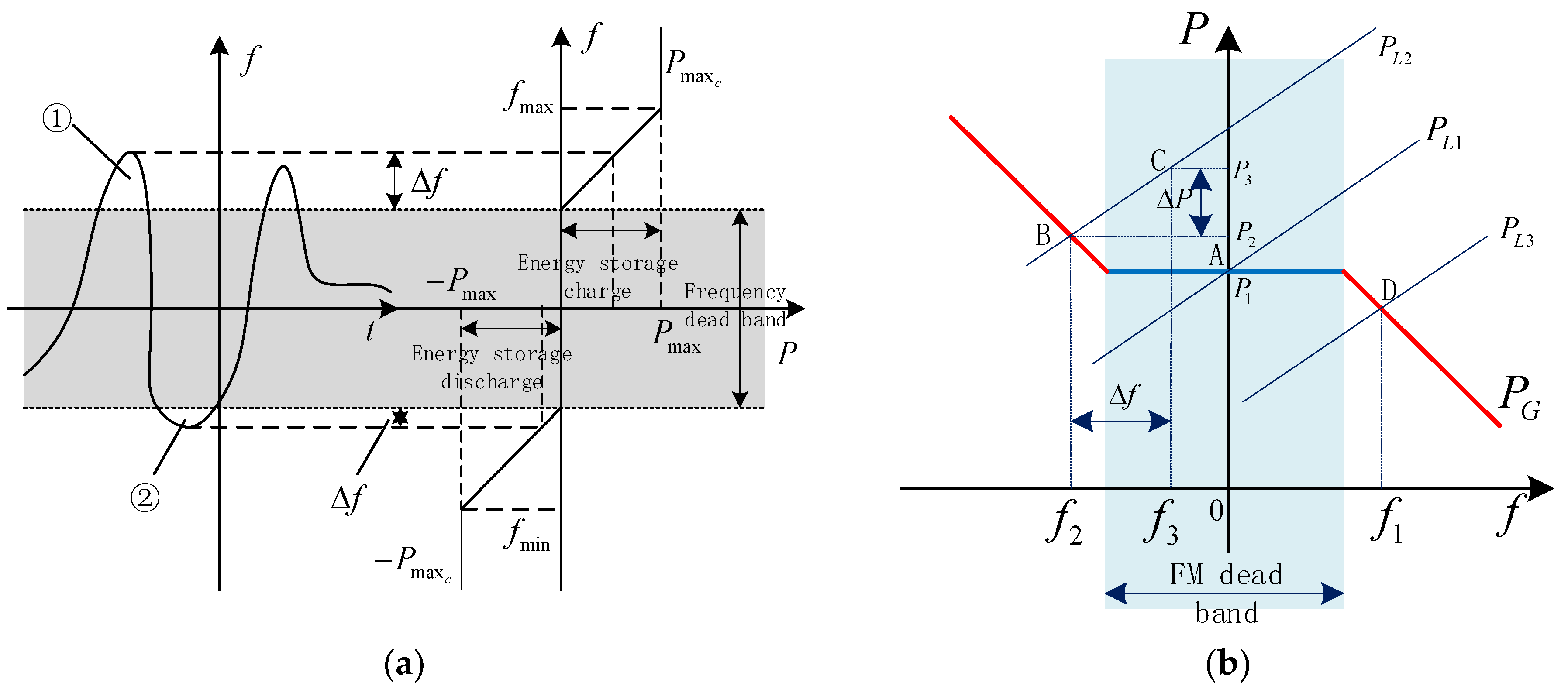
2.1. Principles of Hybrid Energy Storage Participation in Grid Frequency Regulation

In grid frequency regulation, a standard target frequency is typically set to 50 Hz. The grid frequency is then modulated by adjusting the rotational speed of generators to manage the power output [31]. When the actual grid frequency drops below the target threshold, it will be elevated via the regulation system through an increase in the generator speed. Correspondingly, when the frequency exceeds the line, it will be decreased by lowering the generator speed. As depicted in Figure 1a, during the interval labeled ①, energy storage systems are charged to absorb the surplus power from the grid. By contrast, during the interval marked ②, energy storage discharges to offset the grid’s power shortfall, aligning the grid frequency back within the limits of the frequency dead zone. In situations where there is a rapid disturbance necessitating swift transitions in energy storage charging and discharging, we will see the high efficacy of hybrid energy storage in maintaining frequency regulation.
In most instances, the grid utilizes inherent load frequency characteristics and generator units with primary frequency regulation capabilities for frequency control. This method involves the use of rotating inertial mechanical equipment, but the energy conversion process is relatively intricate.
However, hybrid energy storage systems can also engage in frequency regulation, emulating the droop characteristics and inertial control typically seen in standard generator units. Specifically, referring to the frequency deviations and the limitations of the dead zone, the energy storage system determines its output duration and action magnitude. This control function can be implemented using multiple power conversion systems (PCS) for energy storage. That is, when the frequency deviation surpasses the dead zone for frequency regulation actions, and the hybrid energy storage system activates and exchanges power with the grid, while the deviation remains in the dead zone, the system ceases to act. This approach enables proactive participation in grid frequency stabilization, facilitating frequency control. In real-world applications of power system frequency regulation, energy storage predominantly supports traditional generator sets. As illustrated in Figure 1b, the generator’s power–frequency curve P G intersects with the load curve P L 1 when the system frequency is in equilibrium (an ideal state) at point A. Then, as load disturbances and an increase in the load cause the shift from P L 1 to P L 2 , the system’s equilibrium point moves from the balanced point A to the unbalanced point B. At this juncture, the system frequency is f 2 , transgressing the boundary of the dead zone. The hybrid energy storage, as a result, discharges, supplementing the system with the required imbalance of power Δ P . The system’s equilibrium point gradually leaps from B to C, with the frequency remaining at f 3 , which lies within the dead zone and meets the grid’s frequency limits. Similarly, when there is a sudden drop in the load, the load curve will move from P L 1 to P L 3 , the equilibrium point will shift to point D, and the hybrid energy storage will be charged, drawing in the grid’s excess power to realign the frequency inside the frequency dead zone.

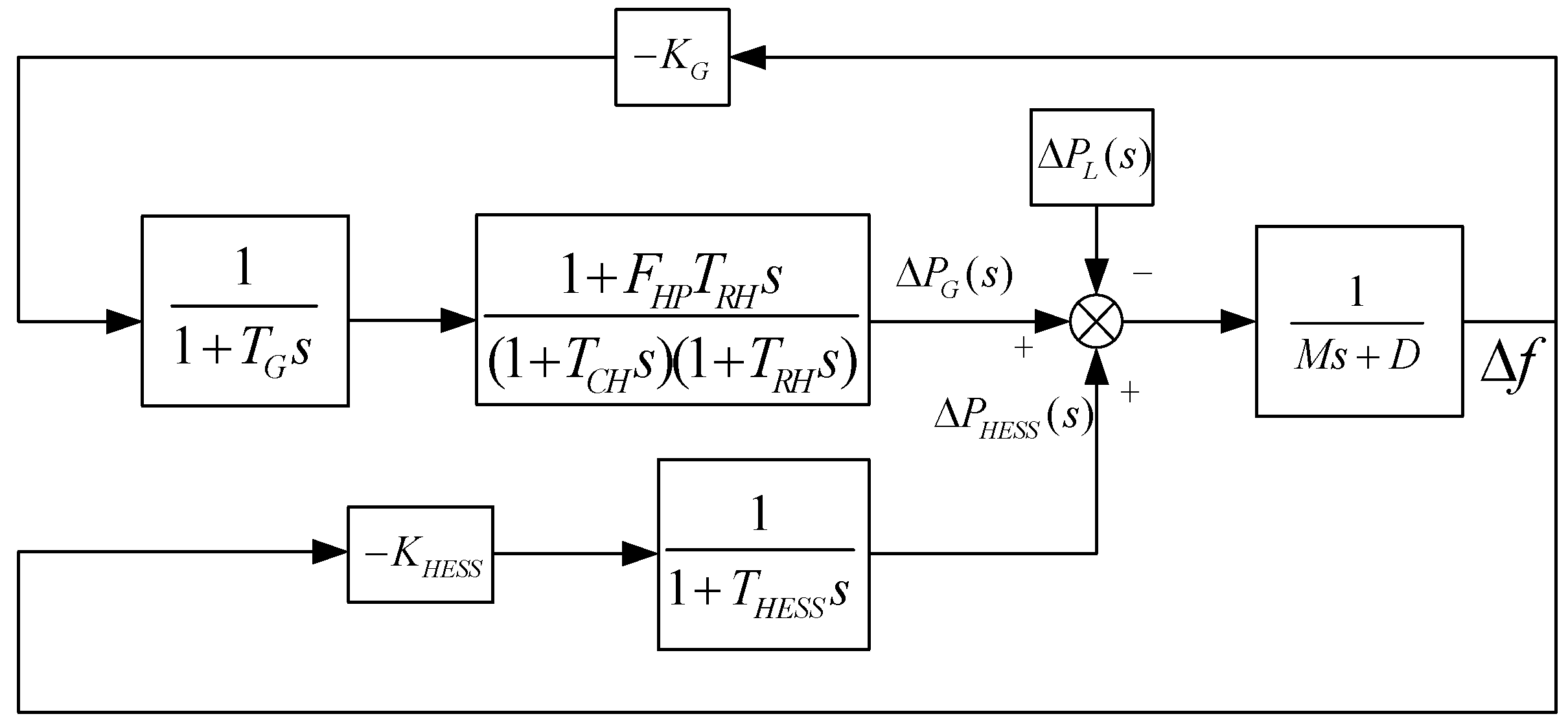
2.2. Regional Electric Grid Frequency Domain Model

The dynamic regional model of the primary frequency regulation system with hybrid energy storage is illustrated in Figure 2. As the figure illustrates, Δ P G ( s ) , Δ P H E S S ( s ) , and Δ P L ( s ) , respectively, represent the output power from the thermal power unit for frequency regulation and from the energy storage station’s hybrid storage and the power disturbance from the load. K G , then, represents the droop coefficient of the thermal power unit, T G is the time constant of the governor, F H P , T R H , and T C H are the parameters of the steam turbine, K H E S S is the droop control coefficient of the energy storage, T H E S S is the time constant of the hybrid energy storage, M is the system’s equivalent inertia, and D is the system’s equivalent damping constant [32].
In Figure 2, the transfer function of the primary frequency regulation system with hybrid energy storage is as follows:
( Δ P G ( s ) + Δ P HESS ( s ) Δ P L ( s ) ) ( M s + D ) 1 = Δ f
{ Δ P G ( s ) = Δ f ( s ) K G G ( s ) Δ P HESS ( s ) = Δ f ( s ) K HESS G HESS ( s )
G ( s ) = 1 + F HP T RH s ( 1 + T g s ) ( 1 + T CH s ) ( 1 + T RH s )
G HESS ( s ) = 1 1 + T HESS s
Given the known historical maximum load fluctuation data for the region, we can determine the target power of the hybrid energy storage from the regional model of the primary frequency regulation system with hybrid energy storage. According to the required power for frequency regulation for energy storage, the power and capacity configuration of the hybrid energy storage is feasible.

3. Capacity Configuration Method for Hybrid Energy Storage

3.1. Northern Goshawk Optimization Algorithm (NGO)

The northern goshawk optimization algorithm is a swarm optimization method introduced in 2022 by Mohammed Dehghani and his colleagues. It simulates the behaviors of the northern goshawk during its prey-hunting process, including prey identification and capture, chasing, and escape actions [33]. This algorithm exhibits superior optimization performance and offers high-precision optimization while maintaining good stability. The fundamental principles of the algorithm are as follows.
(1)
Initialization Phase
This stage serves as the preparatory phase. Populations are randomly initialized within the search space. The population X denotes the initialized group of the northern goshawk:
X = [ X 1   X i   X N ] = [ x 1 , 1 x 1 , j x 1 , m             x i , 1   x i , j x i , m           x N , 1 x N , j x N , m ] N , m
where X i is the position of the northern goshawk, N is the population size of the northern goshawks; m is the dimension of the solution being sought, and x i , j is the position of the j t h dimension for the i t h northern goshawk.
(2)
Identification and Capture Phase (Search Phase)
A northern goshawk begins its hunting with prey identification and capture. In this phase, it randomly selects a prey type and initiates the chase. By executing random prey selection within the search space, this algorithm’s exploratory capabilities can be significantly enhanced. The objective of the process, then, is to determine the optimal region, and we now give a mathematical manifestation of the process, as follows:
P i = X k , i = 1 , 2 , N , k = 1 , 2 , , i 1 , i + 1 , N
x i , j n e w , p i = { x i , j + r ( p i , j I x i , j ) , F p i < F i x i , j + r ( x i , j p i , j ) , F p i F i
X i = { X i n e w , p i , F i n e w , p i < F i X i , F i n e w , p i F i
where P i is the position of the prey selected by the northern goshawk; k is a random integer within the range [1, N], x i , j n e w , p i is the new position of the j t h dimension for the i t h northern goshawk, x i , j is the position of the j t h dimension for the i t h northern goshawk, r is a random parameter used in search and iterative updates, with a range of [0, 1], I is a random parameter used in search and iterative updates, where I can be either 1 or 2, and F i is the objective function value of the i t h northern goshawk.
(3)
Chase and Escape Phase (Exploitation Phase)
This phase simulates the second stage of a northern goshawk’s hunting process. After the hawk attacks its prey, the prey’s attempt to escape prompts the continuation of the chase. Given the goshawk’s remarkable speed, it can chase and ultimately capture its prey under nearly any circumstances. The mimicry of this process can consolidate the algorithm’s ability to locally exploit the search space. In the northern goshawk optimization algorithm, the hunting range’s radius is assumed to be approximately R. The mathematical representation for this phase is as follows:
x i , j n e w , p 2 = x i , j + R ( 2 r 1 ) x i , j
R = 0.02 ( 1 t T )
X i = { X i n e w , p 2 , F i n e w , p 2 F i X i , F i n e w , p 2 F i
x i , j n e w , p 2 is the position of the j t h dimension for the i t h northern goshawk after the update in the second phase, t is the current iteration number, T is the maximum number of iterations, and F i n e w , p 2 is the objective function value of the i t h northern goshawk after the update in the second phase.

3.2. NGO-Optimized VMD

EMD (empirical mode decomposition) and VMD (variational mode decomposition) are two prevalent decomposition methods that can dissect the obtained target power from energy storage stations into power sub-sequences of varying frequencies with strong regularity. While EMD and VMD are both commonly used signal decomposition techniques, their decomposition principles and advantages differ slightly. Compared with EMD, VMD decomposition ensures that every IMF (intrinsic mode function) is a frequency-modulated signal, which means its frequency varies according to time. As a result, VMD can better characterize the time-varying and non-linear features of the original signal. Further, the IMFs resulting from EMD decomposition may not be smooth in the frequency domain, and its decomposition process can easily introduce aliasing, limiting its frequency-modulating capabilities, while VMD provides better control over the decomposition’s precision and speed. However, before executing VMD, there is a need to manually preset certain parameters, which can influence the decomposition’s precision and effectiveness, inducing specific limitations. The efficacy of the decomposition, in turn, is closely linked to the penalty factor α and the decomposition layers K. So, to circumvent the irrationalities brought via the manual parameter setting, we adopt the northern goshawk optimization algorithm to optimize the VMD’s decomposition layers K and the penalty factor α. We expect this to enhance the accuracy and outcome of the decomposition and henceforth refine the power decomposition process of the energy storage station. To validate the efficacy of NGO-optimized VMD, we construct a test signal y ( t ) , as given in the following Formula (12), with 512 sampling points. The decomposition results are presented in Figure 3.
{ y ( t ) = y 1 ( t ) + + y 2 ( t ) + y 3 ( t ) y 1 ( t ) = cos ( 100 π t ) y 2 ( t ) = 1.2 cos ( 200 π t ) y 3 ( t ) = 1.5 sin ( 300 π t )
From Figure 3a, it is evident that signals decomposed using EMD exhibit noticeable aliasing, which can lead to significant errors in subsequent analyses. In Figure 3b, while the use of VMD overcomes the aliasing problem, it introduces the issue of the redundant decomposition of signals with the same frequency, resulting in over-decomposition, for which problem the inappropriate selection of the decomposition layers K is to be blamed. From Figure 3c, it is observable that NGO-optimized VMD accurately decomposes the signal without the issues of over-decomposition or incomplete decomposition, effectively representing the foundational components of the original signal. With this, we opt for NGO-optimized VMD as the method for decomposing the target power of the energy storage station in the subsequent analyses.
To meet the dual requirements for power-type storage (characterized by high power density and rapid charge/discharge speeds) and energy-type storage (known for high energy density and relatively fast charge/discharge speeds) during the frequency regulation process, it is necessary to nonlinearly decompose the target power P t arg e t ( t ) , which includes high-frequency power components and mid-to-low-frequency energy components. Using the NGO-improved VMD method, we reconstructed the decomposed high, mid, and low-frequency components. Among these components, the low-frequency component P l o w ( t ) is allocated for a response via the energy-type storage system, the mid-frequency component P m i d ( t ) via the hybrid battery system (where the energy and power density of the hybrid type lie between those of the energy type and power type) [34], and the high-frequency component P h i g h ( t ) via the power-type storage system. By fully leveraging the unique advantages of these three storage forms, we can get a swift and accurate response to the demand of P t arg e t ( t ) . Moreover, the decomposition via NGO–VMD can help obtain mode components I M F i ( t ) and residue R n ( t ) . Upon reconstructing the decomposed modes, the low-, mid-, and high-frequency components can be represented as:
{ P l o w ( t ) = i = 1 a I M F i ( t ) P m i d ( t ) = i = a b I M F i ( t ) P h i g h ( t ) = i = b n I M F i ( t ) + R n ( t ) P t arg e t ( t ) = P l o w ( t ) + P m i d ( t ) + P h i g h ( t )
where: P l o w ( t ) is the reconstructed low-frequency component, P m i d ( t ) the mid-frequency one, and P h i g h ( t ) the high-frequency one; I M F i ( t ) is the i t h mode decomposed via VMD; and P t arg e t ( t ) is the target power of the energy storage station.

3.3. Mixed Energy Storage Capacity Configuration Strategy

There are self-consumption factors in the active frequency support operation process of the mixed energy storage station. From the literature [35] we inferred that the rated power of the energy storage system surpasses the current system’s target. Within the frequency regulation period T, the excess/deficit power requirement for primary frequency regulation is P t arg e t ( t ) . According to the requirement, the configured P rated should be sufficient to absorb or supplement the maximum excess/deficit power requirement within period T. The power is positive during energy storage charging and negative during discharging. This means the rated power of the energy storage should be capable of meeting the maximum power requirement in the T period, independent of the charging state, to achieve an active power balance. Therefore, the power constraints for energy-type, hybrid-type, and power-type storage are as follows:
P r _ l o w = max ( P l o w ( t ) η c _ l o w , P l o w ( t ) η d _ l o w )
P r _ m i d = max ( P m i d ( t ) η c _ m i d , P m i d ( t ) η d _ m i d )
P r _ h i g h = max ( P h i g h ( t ) η c _ h i g h , P h i g h ( t ) η d _ h i g h )
where P r _ l o w is the rated power configured for the energy-type storage system, P r _ m i d is the rated power configured for the hybrid-type storage system, P r _ h i g h is the rated power configured for the power-type storage system, η c is the charging coefficient of the energy storage, and η d is the discharging coefficient of the energy storage.
Based on the target power P l o w ( t ) , P m i d ( t ) , P h i g h ( t ) in a frequency regulation period t 0 , the cumulative capacity size of the three types of energy storage within one cycle can be computed as follows:
E l o w ( t ) = 0 t 0 P l o w ( t ) d t
E m i d ( t ) = 0 t 0 P m i d ( t ) d t
E h i g h ( t ) = 0 t 0 P h i g h ( t ) d t
where E l o w ( t ) is the accumulated capacity of the energy-type storage system within the cycle t 0 , E m i d ( t ) is the accumulated capacity of the hybrid-type storage system within the cycle t 0 , and E h i g h ( t ) is the accumulated capacity of the power-type storage system within the cycle t 0 .
In consideration of overcharging, over-discharging, and the safety issues of energy storage components, we stipulate the maximum accumulated capacity max E ( t ) and the minimum min E ( t ) . The resulting rated capacity is:
E r _ l o w = max { E l o w ( t ) } min { E l o w ( t ) } S O C l o w max S O C l o w min
E r _ m i d = max { E m i d ( t ) } min { E m i d ( t ) } S O C m i d max S O C m i d min
E r _ h i g h = max { E h i g h ( t ) } min { E h i g h ( t ) } S O C h i g h max S O C h i g h min
where E r _ l o w is the rated capacity of the energy-type storage system, E r _ m i d is the rated capacity of the hybrid-type storage system, E r _ h i g h is the rated capacity of the power-type storage system, S O C l o w max and S O C l o w min , respectively, are the maximum and minimum states of charge (SOCs) for the energy-type storage system, S O C mi d max and S O C mi d min , respectively, are the maximum and minimum states of charge (SOCs) for the hybrid-type storage system, and S O C h i g h max and S O C h i g h min , respectively, are the maximum and minimum states of charge (SOCs) for the power-type storage system.

3.4. Energy Storage Cost

The investment cost for energy storage is a crucial limiting factor. The construction and installation of energy storage devices require a large amount of financial resources. The cost structures of energy storage technologies, such as material costs, manufacturing expenses, and system integration costs, vary along with their types. These costs largely determine the scale and capacity of the energy storage equipment. We refer to the duration during which energy storage devices can operate continuously and provide effective energy storage as the lifespan of the devices. Over time, and with increased frequency of usage, the performance and, hence, capacity of the energy storage devices may decline. Therefore, since a shortened device lifespan can lead to a decrease in storage capacity and thereby affect its economic benefits, we should carefully consider this lifespan degradation in our cost calculations for the devices. To minimize costs, we establish the objective function as:
min C HESS = min ( C low + C mid + C high )
C low = λ ( 1 + λ ) Y low ( 1 + λ ) Y low - 1 [ k low 1 P low + ( k low 2 + k low 3 ) E low ]
C mid = λ ( 1 + λ ) Y mid ( 1 + λ ) Y mid - 1 [ k mid 1 P mid + ( k mid 2 + k mid 3 ) E mid ]
C high = λ ( 1 + λ ) Y high ( 1 + λ ) Y high - 1 [ k high 1 P high + ( k high 2 + k high 3 ) E high ]
where C HESS is the total cost of the hybrid energy storage system, C low , C mid , and C high , respectively, are the costs of the three types of energy storage, Y low , Y mid , and Y high , respectively, are the operational lifespans of the three types of energy storage, k low 1 , k low 2 , and k low 3 , respectively, are the per-unit power costs for energy-type, mixed-type, and power-type storage, k mid 1 , k mid 2 , and k mid 3 , respectively, are the per-unit capacity costs for energy-type, mixed-type, and power-type storage, k high 1 , k high 2 , and k high 3 , respectively, are the operation and maintenance costs per unit capacity for energy-type, mixed-type, and power-type storage, and λ is the discount rate.

4. Case Analysis

Given the frequency domain model of the regional electric grid with energy storage stations, considering the penetration rate of renewable energy and continuous load power disturbances, we configured the capacity of the energy storage station with the simulation analysis of the energy storage station output. We also conducted a comparative analysis of the economic viability of different configuration schemes.

4.1. Simulation Parameter Settings

To verify the rationality of the decomposition method we used for capacity configuration, it is necessary to obtain the power output of the energy storage under load disturbance. Here, we used MATLAB Simulink to establish a regional grid model containing multiple types of energy storage. The regional power grid model parameters are shown in Table 1. The model includes an equivalent traditional unit of 250 MW and an energy storage station composed of three types of energy storage. The energy storage parameters are shown in Table 2. Among them, the units of k1, k2, and k3 are yuan·(MW)−1 and yuan·(MWh)−1, respectively. The discount rate λ is 6%, and the initial water storage of pumped storage is 0.5 (0.5 indicates that the current water storage of the pumped storage is half of the full storage).
The frequency fluctuation duration caused by continuous load disturbance is 1200 s, with a sampling time of 1 s. Figure 4 shows the continuous load disturbance [37] (where the per-unit values are based on the rated capacity of the regional electrical grid).

4.2. Simulation Steps

(1)
Based on the aforementioned simulation parameters, a regional model was built in MATLAB Simulink. The mixed energy storage station was set to assist the thermal power units in primary frequency regulation. Fixed K droop control was implemented in the storage control mode. Under the renewable energy penetration rate of 25%, the system grid interface inertia constant M is 7.5.
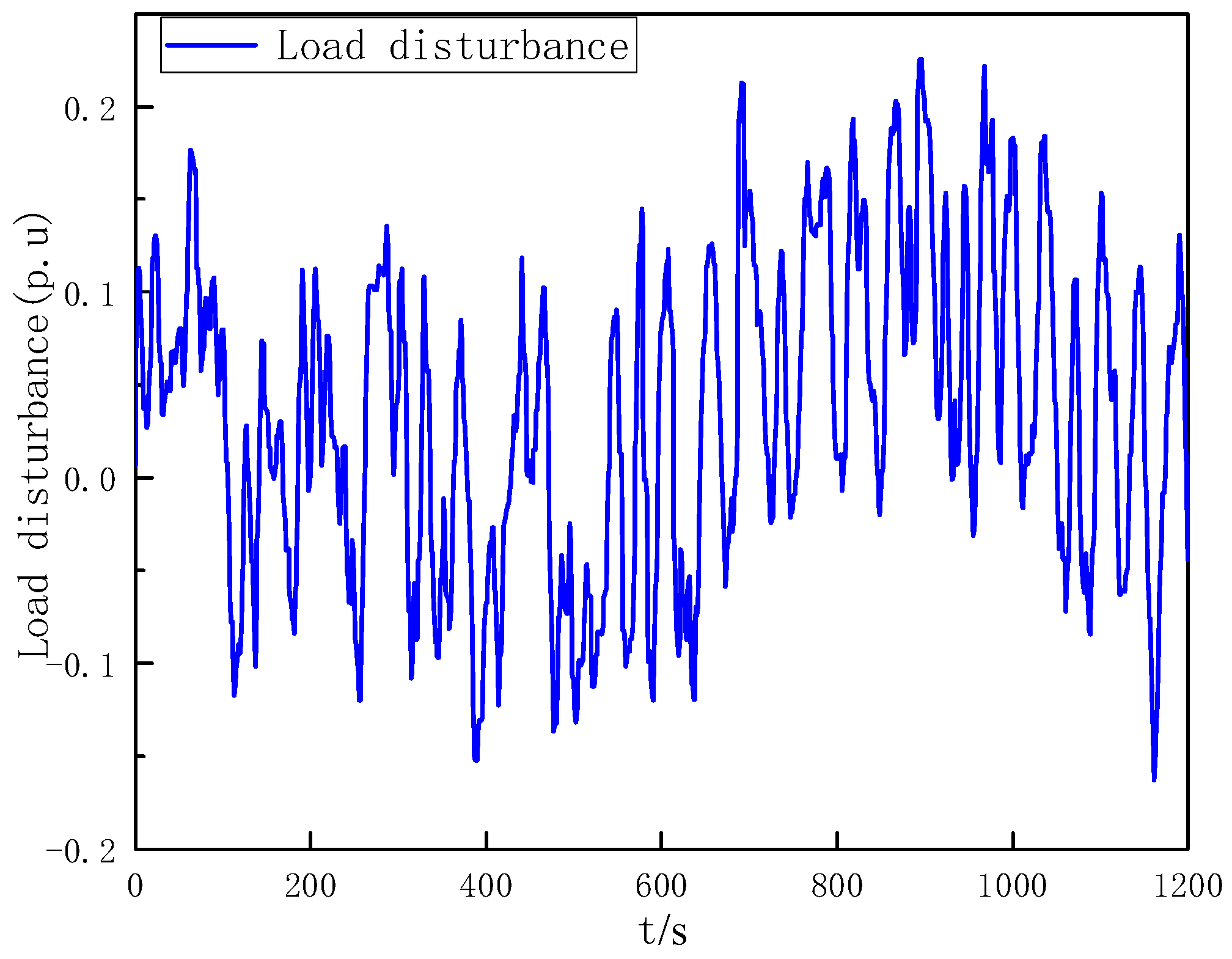
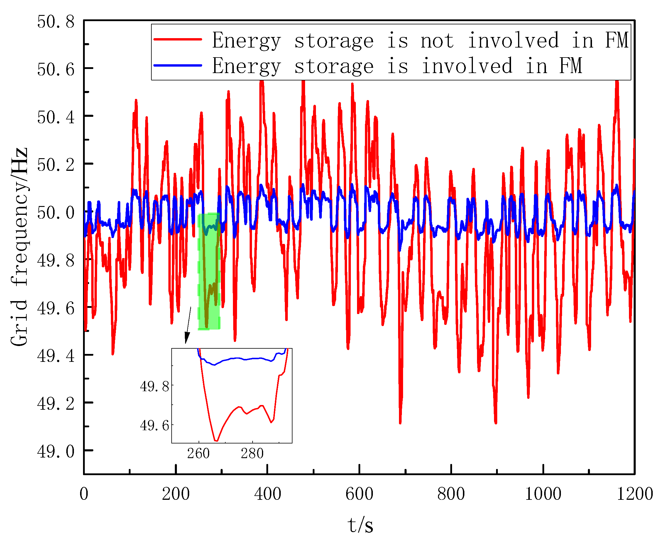
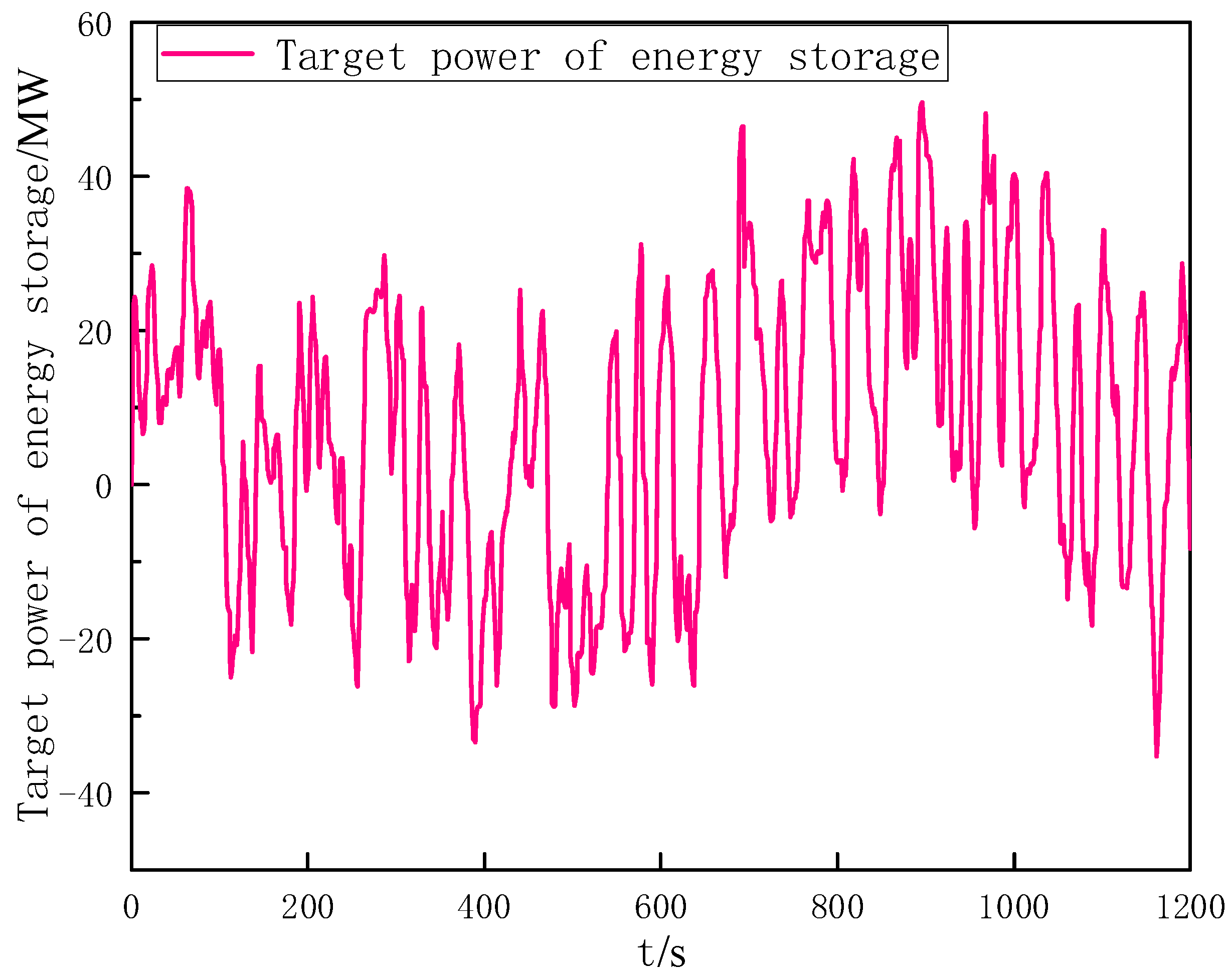
(2)
Incorporating continuous load perturbations into the regional grid model, the simulations yield the frequency profiles of the hybrid energy storage system in scenarios where it does and does not participate in grid frequency regulation, as illustrated in Figure 5. Confronted with significant continuous load disturbances, if the hybrid energy storage station remains non-participatory in frequency regulation, the conventional thermal generation unit alone is not enough to rely on to satisfy the grid frequency requirements (for systems with a capacity below 3000 MW, the permissible frequency deviation stands at 50 ± 0.5 Hz) [38]. By contrast, when the hybrid storage system actively partakes in frequency regulation, the grid’s frequency is kept consistent with the national standards. The energy storage output data of this period, which represents the target power maintaining conformity to grid frequency standards, is depicted in Figure 6.
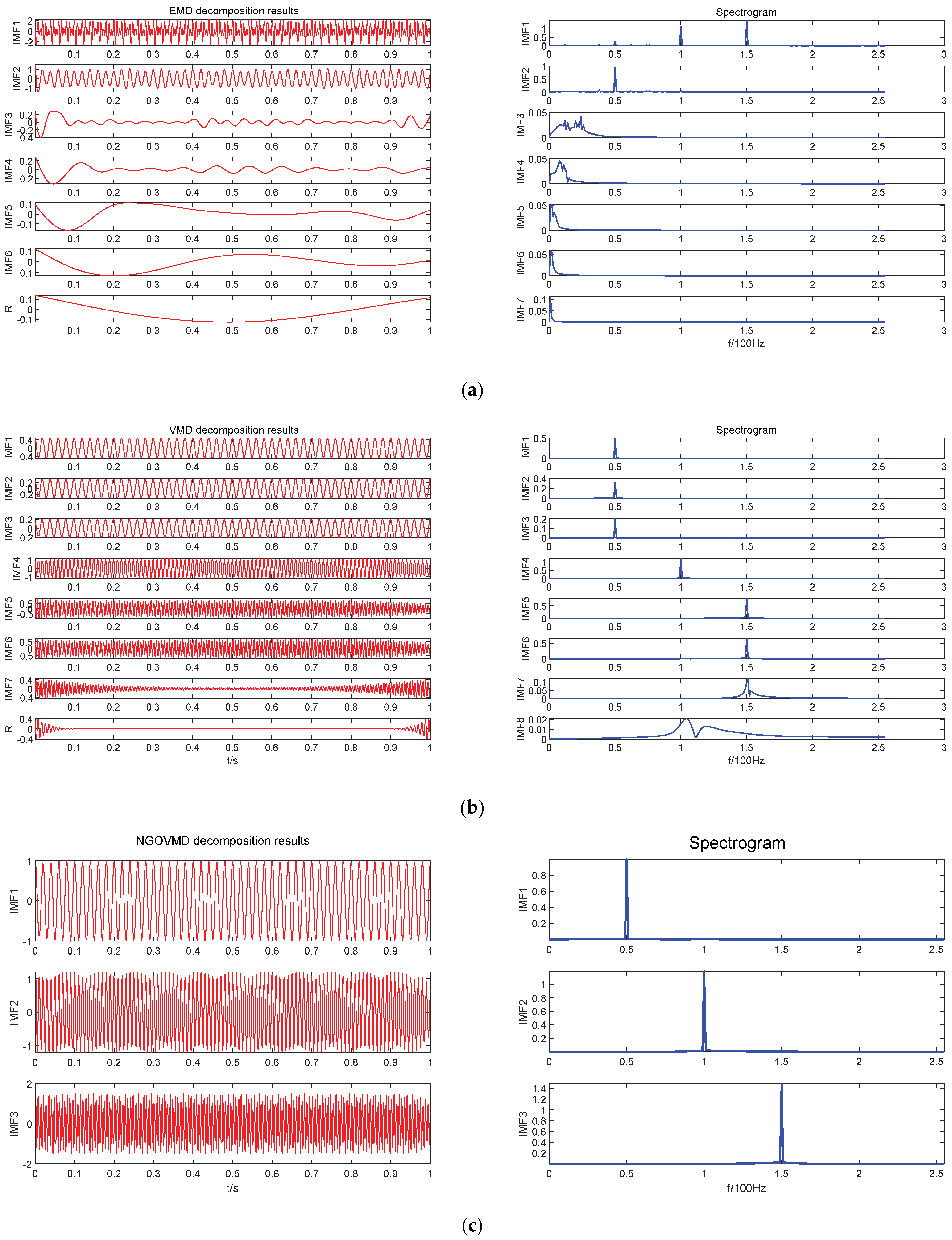
(3)
Utilizing the optimized NGO–VMD decomposition method presented in this paper, the target power P t arg e t of the energy storage station is decomposed. We set the northern goshawk population to 10 with a maximum iteration number of 20. The upper and lower limits for the number of decomposition modes are set to 3 and 15, respectively, and the upper and lower limits for the penalty factor α are set to 100 and 2500, respectively. The other VMD parameters remain at their default values. Through this decomposition method, the decomposition mode number K and the penalty factor for VMD are determined to be 7 and 1523, respectively. The results of this decomposition are shown in Figure 7. The target power P t arg e t is decomposed through NGO–VMD into seven modal components and a residual R, where the seven modalities are correspondingly labeled IMF1 to IMF7, ranking along their frequencies from low to high. In other words, the smaller the mode number, the slower the power component’s frequency and, thus, the stronger the energy characteristics reflected in the curve. The required power for this part stems from the energy storage system with high energy characteristics in the energy storage station. Pumped or compressed storage was chosen according to the local air conditions, and in this paper, we chose pumped storage to support the low-frequency fluctuating power component with high energy characteristics. For power components with frequency fluctuations between high and low, we chose lithium batteries as the energy storage system. As for the power component exhibiting high frequency fluctuations but low energy characteristics, which, so to speak, demonstrate power-type features, we used the supercapacitor system.
According to the above allocation principles, the various power components decomposed via VMD are reconstructed according to Formula (13) to obtain power components of high, middle, and low frequencies. The allocation details for each scheme are shown in Table 3. In the table, the first column represents the mode number, followed by five schemes, L indicates that the power modal component is allocated to the pumped storage system, M shows that the power modal component is allocated to the lithium battery system, and H demonstrates that the power modal component is allocated to the supercapacitor system. Since the smaller the mode number, the stronger the energy characteristics, and the higher the number, the stronger the power characteristics, the pumped storage system is responsible for the power modal component with the highest energy characteristics. It is set so that the lithium battery system can bear, at most, five power modal components. To increase the life of the lithium battery, at least one high-frequency modal power must be allocated to the power-type storage system.
Based on Formula (13), we can deduce:
Scheme   1   { P l o w ( t ) = I M F 1 ( t ) P m i d ( t ) = I M F 2 ( t ) P h i g h ( t ) = i = 3 7 I M F i ( t ) + R ( t ) P t arg e t ( t ) = P l o w ( t ) + P m i d ( t ) + P h i g h ( t )
Scheme   2   { P l o w ( t ) = I M F 1 ( t ) P m i d ( t ) = i = 2 3 I M F i ( t ) P h i g h ( t ) = i = 4 7 I M F i ( t ) + R ( t ) P t arg e t ( t ) = P l o w ( t ) + P m i d ( t ) + P h i g h ( t )
Scheme   5   { P l o w ( t ) = I M F 1 ( t ) P m i d ( t ) = i = 2 6 I M F i ( t ) P h i g h ( t ) = I M F 7 ( t ) + R ( t ) P t arg e t ( t ) = P l o w ( t ) + P m i d ( t ) + P h i g h ( t )
Based on the power reconstructed from each scheme, we can calculate the rated power and rated capacity for each frequency using Formulas (14) to (22). The results are presented in Table 4.
We calculated the total costs of mixed energy storage for each of the six schemes based on Formulas (23) to (26) and the parameters in Table 3. The figures (in units of 100,000 yuan) for the costs are, respectively, 14.673, 13.906, 13.478, 13.619, and 13.494. Based on the results from Table 4, we can see that Scheme 3 has the best economic performance among the schemes without missing the regulation requirements.
The outputs of different components in the mixed energy storage system are shown in Figure 8.
The pumped storage system handles relatively slow power fluctuations. Lithium batteries allocate the power portion between high and low frequencies. The supercapacitor mainly takes on the high-frequency part where the frequency change is the fastest. The three types of energy storage, with their complementary advantages, constitute a mixed energy storage station participating in grid frequency regulation.

5. Conclusions

In this study, referring to variational mode decomposition (VMD) under the northern goshawk optimization algorithm, we proposed a method for the capacity configuration of hybrid energy storage stations. Through the decomposition and reconstruction of the target power of the hybrid energy storage station, we obtained the following conclusions:
(1)
Considering the continuous load disturbance data of the regional power grid, we captured the target power required for the frequency regulation of the regional power grid by simulating the primary frequency regulation model with hybrid energy storage. It can be observed that the target power has both high power and large energy and that hybrid energy storage is the optimal choice for frequency regulation.
(2)
The hybrid energy storage configuration proposed here can effectively utilize the combination of pumped storage power stations, lithium batteries, and supercapacitors to meet the target power requirement of the regional power grid. Since there are various configuration schemes, the rational configuration can reduce the cost of the energy storage station. As the simulation example raised in this paper shows, the most economic configuration, with a cost of 13.478 million yuan, uses a combination of a 29.45 MW pumped storage system whose capacity amounts to 10.57 MWh, a 33.34 MW lithium battery system with a capacity of 4.60 MWh, and an 8.02 MW supercapacitor system whose capacity is 0.67 MWh.
(3)
Taking a 250 MW regional power grid as an example, we established a regional frequency regulation model and conducted a frequency regulation simulation of the regional power grid affected by continuous load disturbance. Then, using the NGO-optimized VMD method for determining the decomposition layer K and the penalty factor α, we verified the rationality of the proposed capacity configuration method, which can provide certain reference significance for the capacity configuration of hybrid energy storage stations.
(4)
The hybrid energy storage capacity allocation method proposed in this article is suitable for regional grids affected by continuous disturbances causing grid frequency variations. For step disturbances, the decomposition modal number in this method is relatively small, and its applicability is limited.

Author Contributions

Conceptualization, H.Z. and X.Z.; methodology, H.Z.; simulation and analysis, H.Z.; validation, H.Z. and Z.W.; formal analysis, H.Z.; investigation, H.Z., K.C. and X.W.; data curation, H.Z. and G.H.; writing—original draft preparation, H.Z.; writing—review and editing, H.Z.; supervision, X.Z.; project administration, X.Z.; literature research, H.Z. All authors have read and agreed to the published version of the manuscript.

Funding

This research was funded by the National Natural Science Foundation of China (51667018) and the Natural Science Foundation of Xinjiang Uygur Autonomous Region (2021D01C044).

Institutional Review Board Statement

Not applicable.

Informed Consent Statement

Not applicable.

Data Availability Statement

Not applicable.

Conflicts of Interest

The authors declare no conflict of interest.

References

  1. McCrone, A.; Moslener, U.; d’Estais, F.; Usher, E.; Grüning, C. Global trends in renewable energy investment 2017. In Bloomberg New Energy Finance; UNEP: Nairobi, Kenya, 2017. [Google Scholar]
  2. Sharma, S.; Huang, S.H.; Sarma, N.D.R. System inertial frequency response estimation and impact of renewable resources in ERCOT interconnection. In Proceedings of the 2011 IEEE Power and Energy Society General Meeting, Detroit, MI, USA, 24–28 July 2011; pp. 1–6. [Google Scholar]
  3. Castillo, A.; Gayme, D.F. Grid-scale energy storage applications in renewable energy integration: A survey. Energy Convers. Manag. 2014, 87, 885–894. [Google Scholar] [CrossRef]
  4. Ding, Q.; Zeng, P.; Sun, Y.; Sun, Y.; Xu, C.; Xu, Z. A planning method for the placement and sizing of distributed energy storage system considering the uncertainty of renewable energy sources. Energy Storage Sci. Technol. 2020, 9, 162–169. [Google Scholar]
  5. Hajiaghasi, S.; Salemnia, A.; Hamzeh, M. Hybrid energy storage system for microgrids applications: A review. J. Energy Storage 2019, 21, 543–570. [Google Scholar] [CrossRef]
  6. Khalid, M. A review on the selected applications of battery-supercapacitor hybrid energy storage systems for microgrids. Energies 2019, 12, 4559. [Google Scholar] [CrossRef]
  7. Wang, B.; Gao, F.; Stanislawski, R.; Krolczyk, G.; Gardoni, P.; Li, Z. Fusion deconvolution for reliability analysis of a flywheel-battery hybrid energy storage system. J. Energy Storage 2022, 49, 104095. [Google Scholar] [CrossRef]
  8. Ma, W.; Wang, W.; Wu, X.; Hu, R.; Tang, F.; Zhang, W. Control strategy of a hybrid energy storage system to smooth photovoltaic power fluctuations considering photovoltaic output power curtailment. Sustainability 2019, 11, 1324. [Google Scholar] [CrossRef]
  9. Barelli, L.; Bidini, G.; Ciupageanu, D.A.; Pelosi, D. Integrating Hybrid Energy Storage System on a Wind Generator to enhance grid safety and stability: A Levelized Cost of Electricity analysis. J. Energy Storage 2021, 34, 102050. [Google Scholar] [CrossRef]
  10. Ye, L.; Wang, K.; Lai, Y.; Chen, H. Review of frequency characteristics analysis and battery energy storage frequency regulation control strategies in power system under low inertia level. Power Syst. Technol. 2023, 47, 446–464. [Google Scholar]
  11. Liu, D.; Zhao, N.; Xu, X.; Shao, P.; Cao, X.; Feng, S. Market-oriented consumption model based on the joint tracking of renewable energy generation curve of “shared energy storage & demand side resources”. Power Syst. Technol. 2021, 45, 2791–2802. [Google Scholar]
  12. Chen, W.; Sun, N.; Ma, Z.; Liu, W.; Dong, H. A Two-Layer Optimization Strategy for Battery Energy Storage Systems to Achieve Primary Frequency Regulation of Power Grid. Energies 2023, 16, 2811. [Google Scholar] [CrossRef]
  13. Almeida, P.R.; Lopes, J.P.; Soares, F.J.; Seca, L. Electric vehicles participating in frequency control: Operating islanded systems with large penetration of renewable power sources. In Proceedings of the 2011 IEEE Trondheim PowerTech, Trondheim, Norway, 19–23 June 2011; pp. 1–6. [Google Scholar]
  14. Meng, G.; Lu, Y.; Liu, H.; Ye, Y.; Sun, Y.; Tan, W. Adaptive Droop Coefficient and SOC Equalization-Based Primary Frequency Modulation Control Strategy of Energy Storage. Electronics 2021, 10, 2645. [Google Scholar] [CrossRef]
  15. Qingxiang, X.U.; Wei TE, N.G.; Xin, W.U.; Yibing LI, U. Capacity configuration method of flywheel storage system for suppressing power fluctuation of wind farms. Energy Storage Sci. Technol. 2022, 11, 3906–3914. [Google Scholar]
  16. Yang, W.; Chang, B. Research on the configuration method & tool for the hybrid energy storage system on the power generation side. Energy Storage Sci. Technol. 2022, 11, 3246–3256. [Google Scholar]
  17. Ding, M.; Wu, J.; Zhang, J. Capacity optimization method of hybrid energy storage system for wind power smoothing. Acta Energiae Solaris Sin. 2019, 40, 593–599. [Google Scholar]
  18. Li, S.; Li, X.; Huang, J.; Liu, W.; Meng, Y.; Xie, Y. Optimal configuration of frequency regulation battery energy storage considering rate characteristics. Acta Energiae Solaris Sin. 2020, 41, 127–132. [Google Scholar]
  19. Su, D.; Lei, Z. Optimal configuration of battery energy storage system in primary frequency regulation. Energy Rep. 2021, 7, 157–162. [Google Scholar] [CrossRef]
  20. Li, C.; Qin, L. Sizing optimization for hybrid energy storage system independently participating in regulation market using improved particle swarm optimization. Acta Energiae Solaris Sin. 2023, 44, 426–434. [Google Scholar]
  21. Li, J.; Qu, S.; Ma, S.; Zeng, W.; Xiong, J. Research on frequency modulation control strategy of auxiliary power grid in battery energy storage system. Acta Energiae Solaris Sin. 2023, 44, 326–335. [Google Scholar]
  22. Liu, Z.; Qi, G.; Gao, J.; Wang, Z. Research on optimal configuration of hybrid energy storage capacity based on adaptive vmd. Acta Energiae Solaris Sin. 2022, 43, 75–81. [Google Scholar]
  23. Fan, Y.; Weiqing, W.; Haiyun, W.; Jing, C.; Xiaozhu, L.; Jiaying, Y. Research on optimization method of primary frequency regulation configuration of wind-storage system considering discharge loss of energy storage. Acta Energiae Solaris Sin. 2022, 43, 416–423. [Google Scholar]
  24. Ji, X.; Liu, D.; Jiang, K.; Kang, Y.; Chen, S.; Dong, T. Primary frequency regulation capacity optimization and wind power coordinated allocation of energy storage-based wind farms. Electr. Power Autom. Equip. 2022, 43, 58–65. [Google Scholar]
  25. Chen, Z.; Liu, B.; Yan, X.; Yang, H. An improved signal processing approach based on analysis mode decomposition and empirical mode decomposition. Energies 2019, 12, 3077. [Google Scholar] [CrossRef]
  26. Chao, C.; Ma, Y.; Chang, Y.; Guan, R. Capacity allocation method of hybrid energy storage system based on empirical mode decomposition and fuzzy chance constrained programming. Distrib. Energy Resour. 2016, 1, 43–48. [Google Scholar] [CrossRef]
  27. Olvera-Guerrero, O.A.; Prieto-Guerrero, A.; Espinosa-Paredes, G. Decay Ratio estimation in BWRs based on the improved complete ensemble empirical mode decomposition with adaptive noise. Ann. Nucl. Energy 2017, 102, 280–296. [Google Scholar] [CrossRef]
  28. Sanabria-Villamizar, M.; Bueno-López, M.; Hernández, J.C.; Vera, D. Characterization of household-consumption load profiles in the time and frequency domain. Int. J. Electr. Power Energy Syst. 2022, 137, 107756. [Google Scholar] [CrossRef]
  29. Dragomiretskiy, K.; Zosso, D. Variational mode decomposition. IEEE Trans. Signal Process. 2013, 62, 531–544. [Google Scholar] [CrossRef]
  30. Zhang, Q.; Wu, J.; Ma, Y.; Li, G.; Ma, J.; Wang, C. Short-term load forecasting method with variational mode decomposition and stacking model fusion. Sustain. Energy Grids Netw. 2022, 30, 100622. [Google Scholar] [CrossRef]
  31. Yan, X.; Li, R.; Cui, S.; Sun, Y.; Li, T. Primary Regulation Method of Grid-connected DFIG Based on Supercapacitor Energy Storage System. High Volt. Eng. 2023, 49, 331–341. [Google Scholar]
  32. Farrokhabadi, M.; König, S.; Cañizares, C.A.; Bhattacharya, K.; Leibfried, T. Battery Energy Storage System Models for Microgrid Stability Analysis and Dynamic Simulation. IEEE Trans. Power Syst. 2018, 33, 2301–2312. [Google Scholar] [CrossRef]
  33. Dehghani, M.; Hubálovský, Š.; Trojovský, P. Northern Goshawk Optimization: A New Swarm-Based Algorithm for Solving Optimization Problems. IEEE Access 2021, 9, 162059–162080. [Google Scholar] [CrossRef]
  34. Zhang, S.; Liu, H.; Wang, F.; Guo, H.; Shi, T. A balancing control strategy for “Power-X-Power” energy storage cluster in system load frequency control. Proc. CSEE 2022, 42, 886–900. [Google Scholar]
  35. Huang, J.; Li, X.; Chang, M.; Li, S.; Liu, W. Capacity allocation of bess in primary frequency regulation considering its technical-economic model. Trans. China Electrotech. Soc. 2017, 32, 112–121. [Google Scholar]
  36. Liu, H.; Xu, X.; Lu, X. Prediction of the cycle life of supercapacitor. Battery Bimon. 2018, 48, 159–162. [Google Scholar]
  37. Fang, H. Research on the Control Strategy of Hybrid Energy Storage Participating in System Frequency Regulation; Qingdao University: Qingdao, Shandong, 2022. [Google Scholar]
  38. Jiang, H.; Pa, H.; Na, C. Island inverter control strategy based on improved virtual oscillator control under mixed load. Power Syst. Prot. Control 2023, 51, 88–96. [Google Scholar]
Figure 1. Frequency regulation droop characteristics of a hybrid energy storage system. (a) The sag characteristics of frequency regulation of energy storage system. (b) The power–frequency characteristics of the auxiliary frequency regulation of a hybrid energy storage system.
Processes 11 02843 g001
Figure 2. Regional model of primary frequency modulation system with hybrid energy storage.
Processes 11 02843 g002
Figure 3. EMD, VMD, and NGO–VMD decomposition results. (a) EMD decomposition results. (b) VMD decomposition results. (c) NGO–VMD decomposition results.
Processes 11 02843 g003
Figure 4. Comprehensive load disturbance of the regional power grid.
Processes 11 02843 g004
Figure 5. Grid frequency.
Processes 11 02843 g005
Figure 6. Hybrid energy storage power station target power.
Processes 11 02843 g006
Figure 7. The modal number of NGO–VMD decomposition.
Processes 11 02843 g007
Figure 8. Each part of the energy storage power station contributes.
Processes 11 02843 g008
Table 1. Simulation parameters of regional power grid, including energy storage power station.
ParameterDescriptionValue
P r a t e d Rated capacity of the grid250 MW
β Wind power permeability25%
P L Load disturbance (p.u.)−0.15~0.2
K G Unit regulated power24
DLoad damping factor1
MConstant of inertia10
T G Steam turbine governor0.08
T c h , T r h , F h p Turbine parameters0.3, 10, 0.5
f d Dead band frequency range −0.03~0.03
Table 2. Hybrid-energy-storage-related parameters [34,36].
ParameterDescriptionPumped StorageLithium BatterySupercapacitors
k1Cost per unit of power5,000,000300,000450,000
k2Cost per unit capacity100,000800,0001,500,000
k3O&M cost per unit capacity10,00020,00020,000
SOCSOC initial value0.50.50.5
YOperating life (year)3099
TypeEnergy storage characteristicsEnergy typeHybrid typePower type
η Charge/discharge efficiency0.85/0.900.85/0.850.90/0.90
T sn Response time(s)100.10.001
Table 3. Target power modal component reconstruction scheme.
I M F i 12345
IMF1LLLLL
IMF2MMMMM
IMF3HMMMM
IMF4HHMMM
IMF5HHHMM
IMF6HHHHM
IMF7HHHHH
R HHHHH
Table 4. The energy storage power and capacity of each reconstruction scheme.
Scheme P r _ l o w /MW P r _ m i d /MW P r _ h i g h /MW E r _ l o w /MWh E r _ m i d /MWh E r _ h i g h /MWh
129.4527.4823.0610.574.672.64
229.4532.9512.7010.574.581.24
329.4533.348.0210.574.600.67
429.4537.657.8110.574.640.45
529.4540.214.7810.574.610.30
Disclaimer/Publisher’s Note: The statements, opinions and data contained in all publications are solely those of the individual author(s) and contributor(s) and not of MDPI and/or the editor(s). MDPI and/or the editor(s) disclaim responsibility for any injury to people or property resulting from any ideas, methods, instructions or products referred to in the content.

