
Influence of Horizontal Multi-Bedding on Hydraulic Fracture Propagation in Shale Reservoirs
Abstract
:1. Introduction
2. Experimental Study
2.1. Determination of Similar Parameters
- (1)
- First theorem of similarity (positive theorem)
- (2)
- Second theorem of similarity (π theorem)
- (3)
- Third theorem of similarity (inverse theorem of similarity)
- 1)
- Geometric parameters: length l.
- 2)
- Physical and mechanical parameters: mass m, density ρ, elastic modulus E, Poisson ratio μ, matrix tensile strength , bedding tensile strength .
- 3)
- Hydraulic characteristic parameters: permeability coefficient k, dynamic viscosity η of fracturing fluid.
- 4)
- Motion parameters: displacement u, strain ε, time t, gravitational acceleration g.
- 5)
- Dynamic parameters: stress σ, pressure P.
- (1)
- The n-related physical quantities involving the physical process of the problem are determined.
- (2)
- The basic m physical quantities covered in the n-related physical quantities are determined.
- (3)
- This consists of (n–m) dimensionless π terms based on basic physical and derived quantities.
- (4)
- The dimension harmony principle is used to determine the value of the undetermined index.
- (5)
- The similarity constant values are determined according to the test conditions.
- (6)
- The relevant physical quantities are determined.
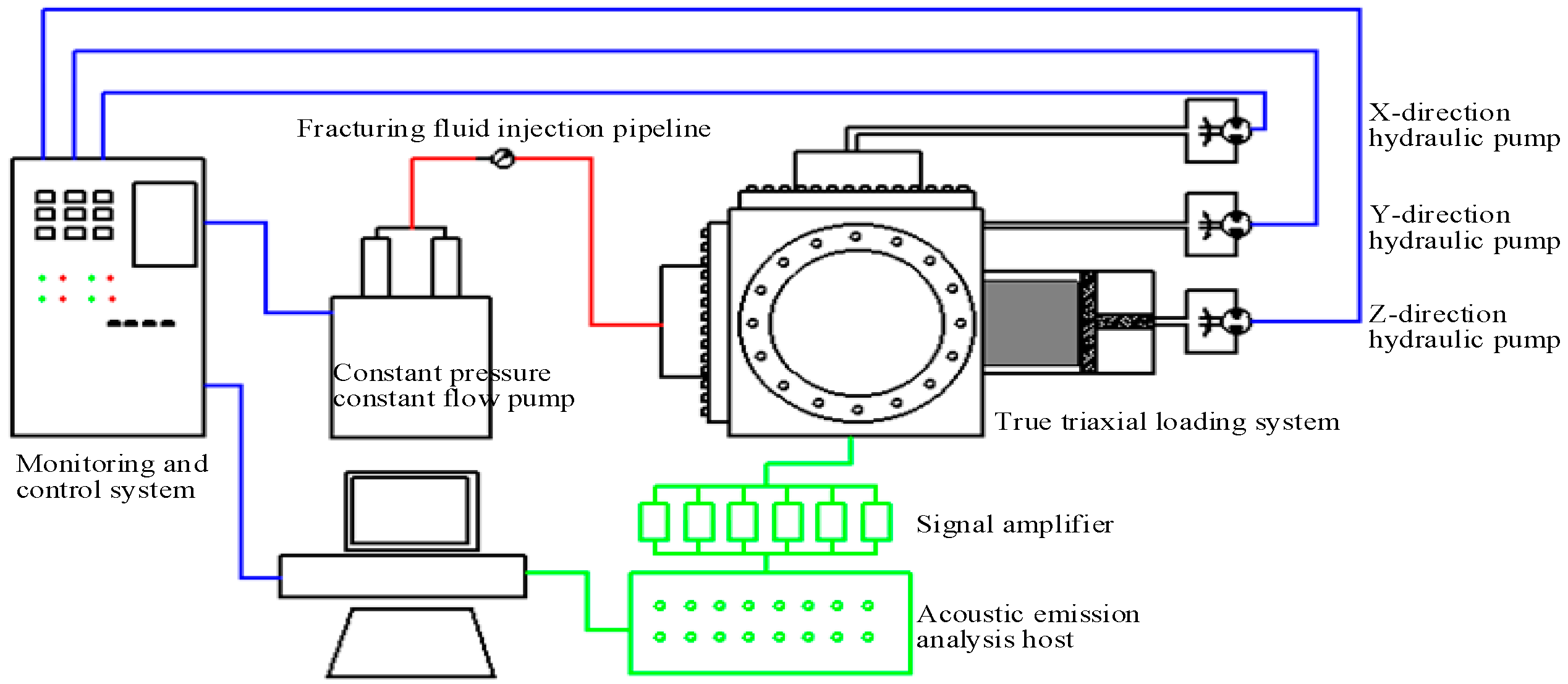
2.2. Experimental Principle and Equipment
2.3. Test Specimen
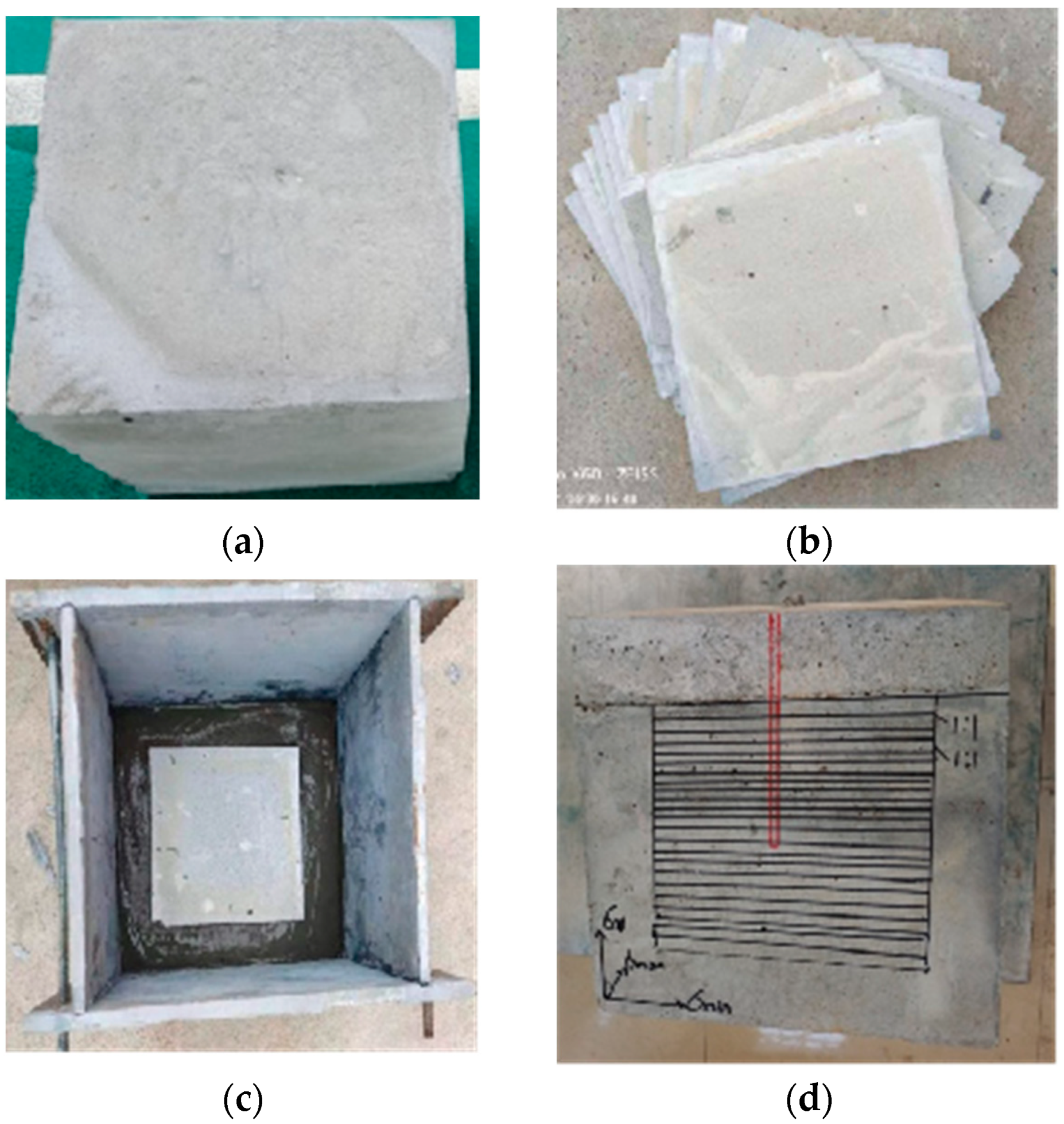
- (1)
- The test specimen is pushed into the fracturing chamber.
- (2)
- Three-axis confining pressure is applied through the hydraulic system and maintained for 2 h.
- (3)
- Fracturing fluid is injected into the core at the set injection rate until the specimen breaks.
- (4)
- The specimen is gradually opened and observed, after which the lengths and heights of the cracks and bedding are observed and measured.
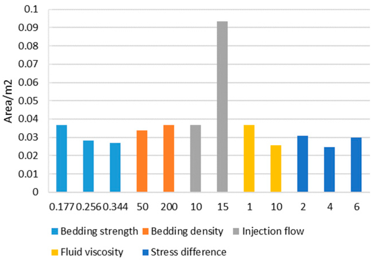
2.4. Fracture Morphology Evaluation in the Hydraulic Fracturing Physical Simulation Experiment
3. Analysis of the Experimental Results
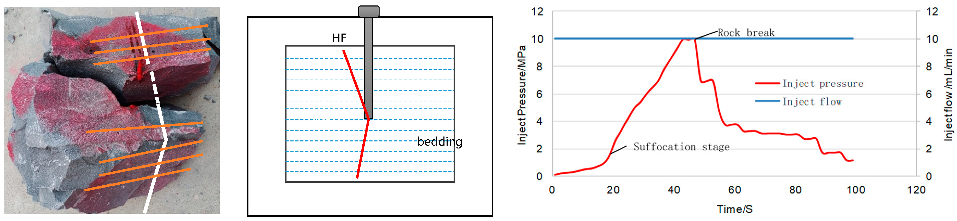
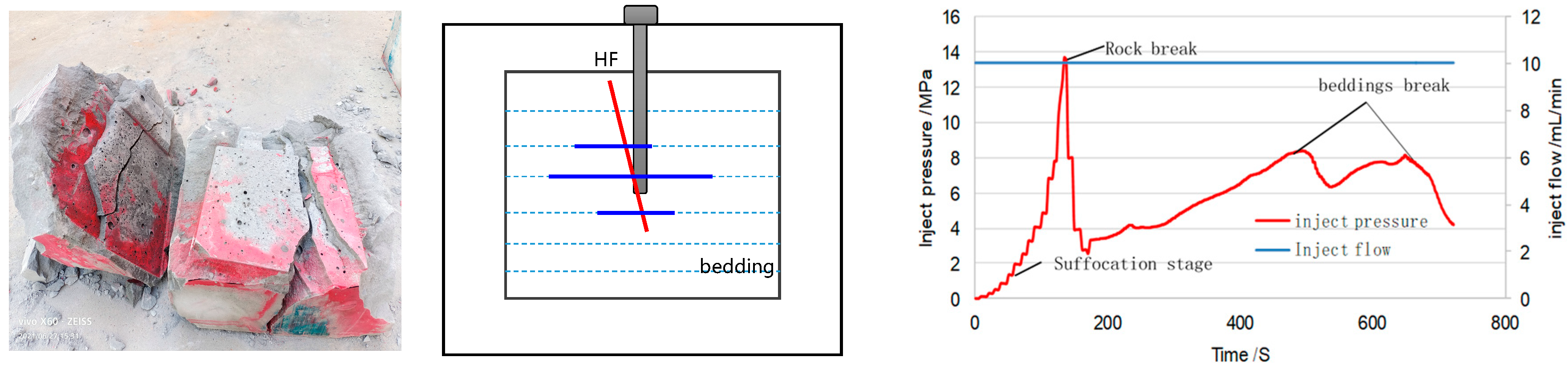
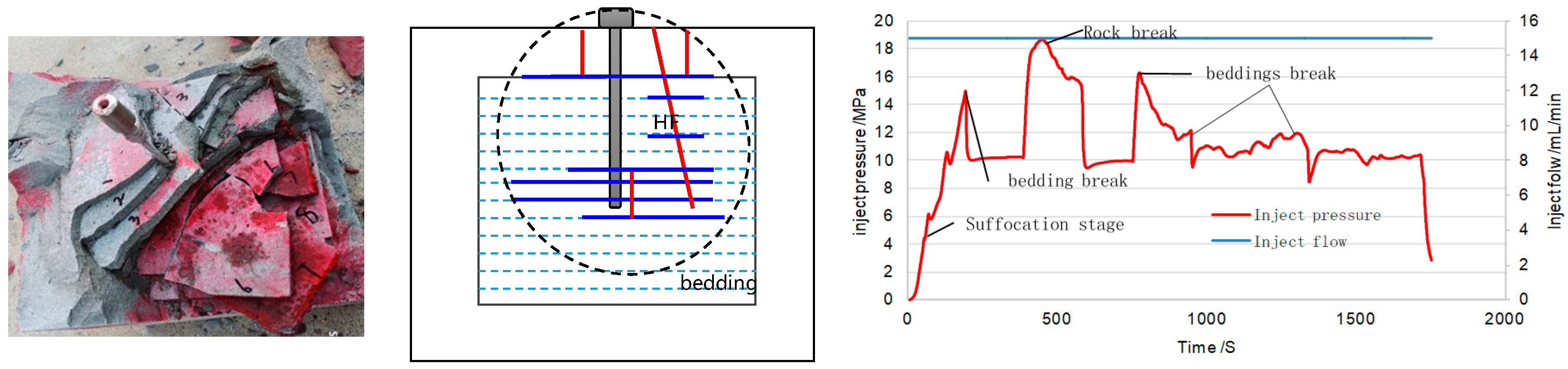
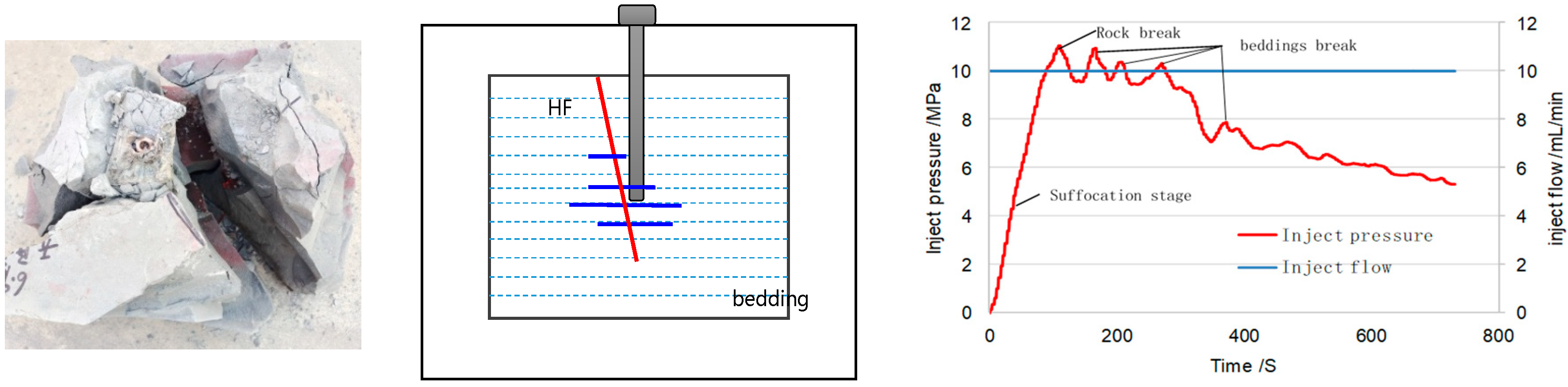
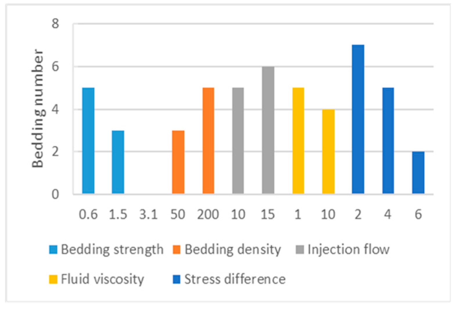
3.1. Effect of Bedding Strength
3.2. Effect of Bedding Density
3.3. Effect of Bedding Flow
3.4. Effect of Fracturing-Fluid Viscosity
4. Discussion
- (1)
- This paper proposes a production method for multilayer hydraulic fracturing specimens and uses SRV to evaluate the effective fracture reconstruction volume. Compared with other experiments, the quantitative analysis of fracturing effect can be carried out only by comparing the number of fractures opened and the pumping curve [18,19].
- (2)
- Compared with raw rock specimens or single-layer bedding experiments [20], the production method of horizontal multilayer bedding specimens proposed in this paper can make a detailed comparative analysis of the influence of different factors on fracture propagation.
- (3)
- Compared with the study by Zhou [21], sensitivity analysis of influencing factors was carried out in this study, and a unique fracturing optimization scheme could be formulated according to different reservoir characteristics.
5. Conclusions
- (1)
- Bedding characteristics are vital for complex fracture formation. A weak bedding cementation strength reduces fracture toughness and increases the chance of activating bedding fractures during hydraulic fracture propagation. The opening of a bedding fracture releases the elastic strain energy of the fracturing fluid, which limits the hydraulic fracture height.
- (2)
- A higher bedding density increases the injection displacement and reduces the injection fracturing-fluid viscosity, opening more bedding fractures with a complex morphology.
- (3)
- A higher bedding strength yields simpler fractures and increases the injection rate, fracturing-fluid viscosity, hydraulic fracture penetration ability, and fracture height.
- (4)
- For a fracturing interval with well-developed bedding and easy opening, it is necessary to increase the displacement, amount, and proportion of high-viscosity fracturing fluid to reduce the limiting effect of the bedding on fracture height expansion. For a fracturing interval with undeveloped bedding and difficult opening, it is necessary to increase the displacement and reduce the viscosity of the fracturing fluid to improve fracture complexity and increase the gas release area.
Author Contributions
Funding
Data Availability Statement
Conflicts of Interest
References
- Caineng, Z.; Songqi, P.; Zhenhua, J.; Jinliang, G.; Zhi, Y.; Songtao, W.; Qun, Z. Shale oil and gas revolution and its impact. Acta Pet. Sin. 2020, 41, 1–12. [Google Scholar] [CrossRef]
- Vega, B.; Kovscek, A.R. Fractal Characterization of Multimodal, Multiscale Images of Shale Rock Fracture Networks. Energies 2022, 15, 1012. [Google Scholar] [CrossRef]
- Ferguson, B.; Agrawal, V.; Sharma, S.; Hakala, J.A.; Xiong, W. Effects of Carbonate Minerals on Shale-Hydraulic Fracturing Fluid Interactions in the Marcellus Shale. Front. Earth Sci. 2021, 22, 695978. [Google Scholar] [CrossRef]
- Zhang, Y.P.; Wei, X.; Tang, P.F. Fracture propagating mechanism and fracturing engineering technology in Gulong shale oil reservoirs of Songliao Basin. Pet. Geol. Oilfield Dev. Daqing 2020, 39, 170–175. [Google Scholar]
- Zhou, W.G.; Wang, S.B.; Yang, H.Q. Three-dimensional Numerical Simulation of Hydraulic Fracture Propagation Path Considering Weak Shale Bedding. Drill. Prod. Technol. 2021, 44, 15–19. [Google Scholar]
- Daneshy, A.A. Hydraulic fracture propagation in layered formations. Soc. Pet. Eng. J. 1978, 18, 33–41. [Google Scholar] [CrossRef]
- Teufel, L.W.; Clark, J.A. Hydraulic fracture propagation in layered rocks: 26 experimental studies of fracture containment. Soc. Pet. Eng. J. 1984, 24, 19–32. [Google Scholar] [CrossRef]
- Olson, J.E.; Bahorich, B.; Holder, J. Examining Hydraulic Fracture: Natural Fracture Interaction in Hydrostone Block Experiments. In Proceedings of the SPE Hydraulic Fracturing Technology Conference, The Woodlands, TX, USA, 6–8 February 2012. [Google Scholar] [CrossRef]
- Shen, Z.Y.; Zhou, L.J.; Li, X.J.; Zhang, X.Y.; Zhou, L. Hydraulic fracturing characteristics of laminated shale and its enlightenment to fracture pressure. Coal Sci. Technol. 2023; online. [Google Scholar]
- Zhao, H.F.; Chen, M.; Jin, Y. Extending behavior of hydraulic fracture on formation interface. Acta Pet. Sin. 2009, 30, 450–454. [Google Scholar] [CrossRef]
- Bryant, E.C.; Sun, W. A mixed-mode phase field fracture model in anisotropic rocks withconsistent kinematics. Comput. Methods Appl. Mech. Eng. 2018, 342, 561–584. [Google Scholar] [CrossRef]
- Khalid, P.; Ehsan, M.I.; Metwaly, M.; Khurram, S. Mechanical and Elastic Characterization of Shale Gas Play in Upper Indus Basin, Pakistan. Arab. J. Sci. Eng. 2021, 46, 5767–5781. [Google Scholar] [CrossRef]
- Yushi, Z.; Xinfang, M.; Shicheng, Z.; Tong, Z.; Han, L. Numerical investigation into the influence of bedding plane on hydraulic fracture network propagation in shale formations. Rock Mechchanics Rock Eng. 2016, 49, 3597–3614. [Google Scholar] [CrossRef]
- Zhou, T.; Zhang, S.C.; Zou, Y.S.; Li, N.; Zheng, Y.H. Hydraulic Fracture Geometry of Shale Gas Reservoirs with Strong Tectonic Stress and Large Dip Angle in Northeastern Margin of Sichuan Basin. Xinjiang Pet. Geol. 2016, 37, 336–341. [Google Scholar] [CrossRef]
- Dehghan, A.N.; Goshtasbi, K.; Ahangari, K.; Jin, Y. The effect of natural fracture dip and strike on hydraulic fracturepropagation. Int. J. Rock Mech. Min. Sci. 2015, 75, 210–215. [Google Scholar] [CrossRef]
- Sun, K.M.; Ji, H.J.; Zhang, S.C. Influence of bedding azimuth and strength on hydraulic fracturing in shale. J. Exp. Mech. 2020, 35, 164–169. [Google Scholar] [CrossRef]
- Aminul-Aleagha, M.D.; Skalle, R. An Experimental Investigation of Shale Mechanical Properties Through Drained and Undrained Test Mechanisms. Rock Mech. Rock Eng. 2013, 46, 1391–1413. [Google Scholar]
- Heng, S.; Li, X.; Liu, X.; Chen, Y. Experimental study on the mechanical properties of bedding planes in shale. J. Nat. Gas Sci. Eng. 2020, 76, 203161. [Google Scholar] [CrossRef]
- Jamil, M.; Siddiqui, N.A.; Rahman, A.H.B.A.; Ibrahim, N.A.; Ismail, M.S.B.; Ahmed, N.; Usman, M.; Gul, Z.; Imran, Q.S. Facies Heterogeneity and Lobe Facies Multiscale Analysis of Deep-Marine Sand-Shale Complexity in the West Crocker Formation of Sabah Basin, NW Borneo. Appl. Sci. 2021, 11, 5513. [Google Scholar] [CrossRef]
- Li, Y.C.; Ma, X.F.; Li, N.; Xiao, J.; He, F.; Zhang, Y.N.; Liu, Z. Experimental study on influence of bedding planes on stimulation effect of hydraulic fracturing in shale reservoir. J. Xi’an Shiyou Univ. 2017, 32, 62–67. [Google Scholar]
- Tong, Z.H.; Haibo, W.A.; Fengxia, L.I.; Yuanzhao, L.; Yushi, Z.; Zhang, C. Numerical simulation of hydraulic fracture propagation in laminated shale reservoirs. Pet. Explor. Dev. 2020, 47, 1039–1051. [Google Scholar]


| C1 | Cm | CE | Ck | Cg | Cu | Ct | ||||||
|---|---|---|---|---|---|---|---|---|---|---|---|---|
| 10 | 1000~2000 | 1~2 | 10 | 10 | 10 | 1 | 10 | 10 | 10 |
| Tensile Strength | Elastic Modulus | |||
|---|---|---|---|---|
| The bedding is perpendicular to the loading direction | The bedding is parallel to the loading direction | The bedding is perpendicular to the loading direction | The bedding is parallel to the loading direction | |
| A block of shale in Sichuan | 4.16 | 1.04 | 15.20 | 29.00 |
| Similar shale | 0.42 | 0.10 | 1.5 | 2.9 |
| Specimen Type | ms: mg: mc: mw | Tensile Strength/MPa |
|---|---|---|
| Stroma | 1: 1: 0.3: 0.25 | 0.775 |
| Low-strength bedding | 8: 1: 0.0: 0.25 | 0.177 |
| Medium-strength bedding | 4: 1: 0.0: 0.25 | 0.256 |
| High-strength bedding | 2: 1: 0.0: 0.25 | 0.344 |
| Rock Sample No. | Specimen Type | Density (Bedding/m) | Displacement (mL/min−1) | Viscosity (mPa·s) |
|---|---|---|---|---|
| D 1 | Low-strength bedding | 20 | 10 | 1 |
| D 2 | Low-strength bedding | 20 | 15 | 1 |
| D 3 | Low-strength bedding | 20 | 10 | 10 |
| D 4 | Low-strength bedding | 5 | 10 | 1 |
| Z 5 | Medium-strength bedding | 20 | 10 | 1 |
| G 6 | High-strength bedding | 20 | 10 | 1 |
Disclaimer/Publisher’s Note: The statements, opinions and data contained in all publications are solely those of the individual author(s) and contributor(s) and not of MDPI and/or the editor(s). MDPI and/or the editor(s) disclaim responsibility for any injury to people or property resulting from any ideas, methods, instructions or products referred to in the content. |
© 2023 by the authors. Licensee MDPI, Basel, Switzerland. This article is an open access article distributed under the terms and conditions of the Creative Commons Attribution (CC BY) license (https://creativecommons.org/licenses/by/4.0/).
Share and Cite
Jiang, M.; Wei, Y.; Li, T.; Dong, K. Influence of Horizontal Multi-Bedding on Hydraulic Fracture Propagation in Shale Reservoirs. Processes 2023, 11, 2846. https://doi.org/10.3390/pr11102846
Jiang M, Wei Y, Li T, Dong K. Influence of Horizontal Multi-Bedding on Hydraulic Fracture Propagation in Shale Reservoirs. Processes. 2023; 11(10):2846. https://doi.org/10.3390/pr11102846
Chicago/Turabian StyleJiang, Minzheng, Yuyang Wei, Tingting Li, and Kangxing Dong. 2023. "Influence of Horizontal Multi-Bedding on Hydraulic Fracture Propagation in Shale Reservoirs" Processes 11, no. 10: 2846. https://doi.org/10.3390/pr11102846