1. Introduction
As part of the global change towards a sustainable chemical industry, developing new chemical processes based on renewable resources as an alternative to increasingly scarce fossil reserves is essential. Oleo-chemicals, produced from natural fats and oils, can be modified to have properties suitable for bio-based monomers for polymer production, with exceptionally high potential as drop-in solutions for conventional petrochemical monomers [
1,
2,
3].
Here, homogeneous transition metal catalysts enable new synthesis routes based on oleo-chemicals, featuring high atom economy and energy efficiency as well as a reduction of waste due to their high selectivity [
4], following a sustainable development in line with the sustainability goals proposed by the United Nations [
5]. Homogeneously catalyzed reactions can typically be operated under mild conditions, as phase transfer limitations are reduced compared to heterogeneously catalyzed reactions. At the same time, a downstream separation of catalyst and product phase is indispensable—on the one hand, to meet purity requirements as the transition metals are often toxic [
6], and on the other hand, to enable recycling of the often high-priced catalysts for the economical operation of these processes [
7,
8]. This downstream separation is challenging because multiple phenomena can reduce catalytic activity, including physical loss, leaching to the product phase, and deactivation (thermal and chemical) [
8]. Conventional separation methods, including distillation, extraction, and membrane processes, are limited regarding their separation efficiency while maintaining the sensitive catalysts in an active state [
7,
9]. Therefore, innovative strategies for separating and recycling homogeneous catalysts have become the focus of research during the past years [
7,
10]. These strategies include particularly sophisticated separation methods based on catalyst immobilization [
7,
11,
12,
13] and multiphase systems [
7,
14,
15,
16]. A common weakness of these approaches is the required tradeoff between suitable conditions for the catalyst and a feasible separation.
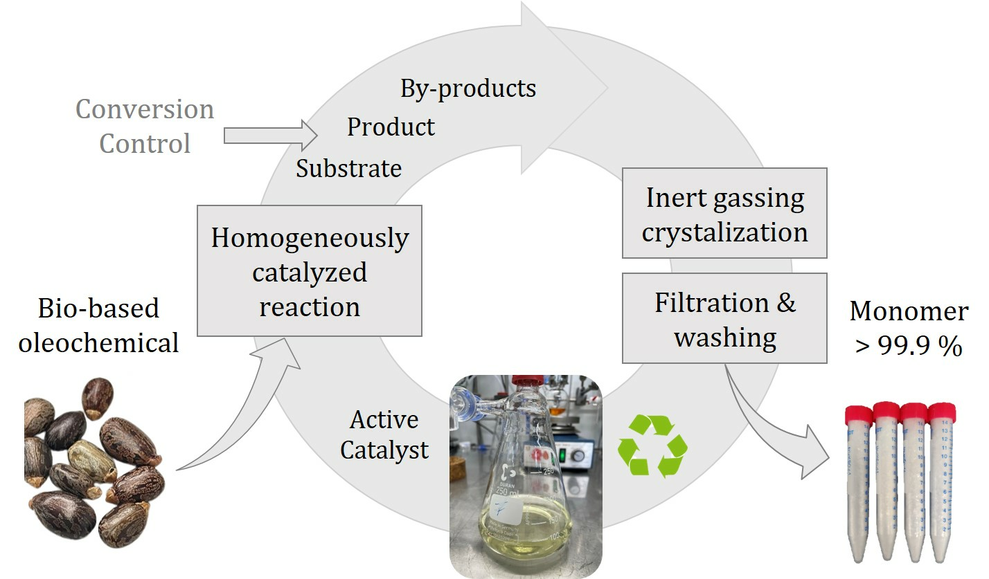
As an alternative, selective product crystallization has been investigated in our research groups during the past years as another promising strategy for separating and recycling homogeneous catalysts [
17,
18,
19,
20,
21]. In this strategy, the reaction product is selectively crystallized from the homogeneous solution upon cooling, using the distinct differences in solubility of the product and catalyst. After the separation of the crystalline product phase by filtration and further purification in a washing step, a pure product is obtained. At the same time, simultaneously, the homogeneous catalyst is recovered in the filtrate for recycling. Compared to the other separation methods, a significant benefit of crystallization is its highly selective nature, enabling the formation of a crystalline product phase, which can be isolated by suitable filtration and washing procedures as a pure product. In addition, the catalyst does not need to be modified with, e.g., sulfonate groups to increase solubility, and crystallization is feasible from the reaction solvent methanol, which also serves as a substrate without further additives. Therefore, the catalyst is in its optimal state.
In preceding investigations from our research groups, we demonstrated that due to the comparably mild conditions during separation by cooling crystallization, the catalytic activity is preserved while achieving a high product yield and purity in the product phase. In the methoxycarbonylation of methyl oleate, a homogeneous palladium catalyst was maintained active during eight recycling runs, achieving a cumulated catalyst turnover number ∑TON of 2800 [
19]. The functionalized 1,19-dimethyl nonadecanedioate was isolated with an average product yield of ≈50% and purity of ≈93%, whereas both exhibited a decreasing trend over the recycling runs. In our subsequent work [
20], using the same catalyst system for the methoxycarbonylation of methyl 10-undecenoate (C
11-ME) with systematically optimized reaction conditions, these results were even exceeded with a ∑TON of 4600 in only five recycling steps and product yield of 82% with an average product purity of 98%. Still, the yield and purity decreased with each recycling step in this study. Catalyst leaching to the product was 10.6% [
20].
Building on our work [
20], we have recently focused on improving the steps of crystallization, filtration, and washing in systematic investigations, which revealed a high potential for further process optimization regarding purity [
22,
23]. In the present study, we aim to implement the optimized procedures in the integrated catalyst recycling process, focusing on a constant high product purity over consecutive recycling runs. Here, one objective is the reduction of leaching of the catalyst to the product. Moreover, combining the highly selective nature of homogeneous catalysis and crystallization, our objective is the further maximization of purity to produce polymer-grade products (>99.9%) without further downstream purification. In polycondensation reactions, e.g., towards polyesters or polyamides, monomer purity is decisive for the achievable polymerization degree, and particularly, monofunctional monomers are critical as they stop the chain growth [
24]. For the purification of dodecanedioic acid, which is a similar monomer used in the production of polyamides or polyesters, elaborate procedures are applied, achieving a purity of up to >99.9% desirable for polymerization [
25,
26,
27].
Our investigated model reaction system, the methoxycarbonylation of methyl 10-undecenoate (C
11-ME), derived from natural castor oil, to linear 1,12-dimethyl dodecanedioate (
l-C
12-DME), is schematically depicted in
Figure 1.
The reaction is catalyzed by a homogeneous organometallic catalyst complex depicted in
Figure 1, which is formed from a palladium precursor Pd
2(dba)
3, ligand 1,2-DTBPMB and methanesulfonic acid (MSA) as co-catalyst. Despite substrate isomerization (
iso-C
11-ME) in the presence of the catalyst, this catalytic system features a highly selective functionalization of the terminal double bond to form the linear target product
l-C
12-DME at a constant selectivity of 95% [
20]. As a major branched by-product, the depicted
iso-C
12-DME is formed, besides minor quantities of further branched by-products
b-C
12-DME.
In an integrated process, the composition of the reaction mixture is a critical input for further product purification by crystallization, filtration, and washing. On the contrary, the components recycled in the filtrate affect the reaction step, particularly the remaining amount of active catalyst. In
Figure 2, the major complex interactions of variable process inputs and critical output parameters regarding reaction, crystallization, and solid–liquid separation via filtration and washing are schematically depicted and will be further explained in the following.
The composition in the reaction mixture is determined in the reaction step, whereby the substrate conversion X is a decisive parameter, assuming constant selectivity of the homogeneous catalyst. The conversion is adjustable via the reaction time and (initial) substrate concentration, which is maintained constant by re-dosing in a recycling process. Furthermore, the catalytic activity is crucial. In our preceding investigations, we verified a high sensitivity of the homogeneous catalyst towards high substrate loadings, indicating a maximum feasible Pd:substrate ratio of 1:1000. Furthermore, thermal catalyst degradation by the formation of Pd black during long reaction durations at high temperatures was observed [
20]. Consequently, a limitation of reaction time is useful for the preservation of catalytic activity, which is reached by purposefully ending the reaction at incomplete conversion.
The purification from a complex reaction mixture with multiple impurities typically poses a challenge. The achievable crystallization yield
Ycryst depends on the initial product concentration as well as the final equilibrium concentration adjustable via the crystallization end temperature. Furthermore, the concentrations of structurally similar substrates and by-products are decisive, as these components affect product solubility and could potentially be incorporated into the crystal lattice. However, in a study of solid–liquid equilibria, no thermodynamic limitations for crystallizing
l-C
12-DME as a pure solid from the reaction mixture were found. Moreover, within a temperature window above 0 °C for cooling crystallization, only pure
l-C
12-DME crystallizes, whereas all further components are retained in the liquid mother liquor [
20]. Nevertheless, the achievable purity can be diminished by secondary processes during crystallization, e.g., agglomeration, which causes entrapment of contaminated mother liquor among the agglomerated crystals [
28]. Furthermore, the final purity also depends on the consecutive steps of filtration and washing, where the actual separation of crystallized product from mother liquor takes place.
The efficiency of these downstream solid–liquid separation steps is closely linked to the product quality set in the crystallization step, particularly particle size distribution (PSD) and the shape defining the filterability. For an efficient separation, particle size and shape should be ideally uniform [
29,
30,
31]. A controlled crystallization is crucial to produce suitable product crystals for an efficient separation. Here, we have recently presented the concept of inert gassing crystallization for enhanced purification of
l-C
12-DME [
22,
23]. In gassing crystallization, upon cooling below the solubility, gas bubbles are introduced into the supersaturated solution, thus reducing the energy for the initial formation of crystal nuclei on the bubble surface, inducing primary heterogeneous nucleation [
32]. For the crystallization of
l-C
12-DME, we could demonstrate that compared to simple cooling crystallization with spontaneous nucleation from the solution, by gassing crystallization using inert argon, fewer nuclei are formed which grow to larger, more uniform crystals with a reduced agglomeration level, achieving the target purity of >99.9% [
22,
23]. However, in our preceding investigations, a significant impact of substrate and isomers, as well as branched by-products, on
l-C
12-DME crystallization was identified. With increasing concentration of these structurally similar components,
l-C
12-DME solubility is increased, thus reducing the amount of crystallizing product, i.e., the crystallization yield. Furthermore, these components strongly promote agglomeration among
l-C
12-DME particles, reducing product purity and increasing catalyst leaching. As a consequence, in an integrated recycling process focusing on high product purity, the concentration of these components must be maintained below a critical limit so that a purge has to be considered after a certain number of recycling runs. The final purity, the catalyst leaching, and the recovery of product particles and filtrate further depend on the wash ratio used in the washing steps, defining the volume ratio of wash liquid to the filter cake pores filled with the remaining reaction solution. Thus, the composition of the recycled filtrate depends on all steps of crystallization, filtration, and washing. Maintaining catalyst activity is linked to the objective of a high product purity, which goes along with minimizing the leaching of catalyst solution to the product phase. However, further mechanisms, including physical loss and deactivation, e.g., by ligand oxidation in the presence of oxygen or water, can cause a decline in catalytic activity during recycling.
Overall, major challenges are the complex interactions of different process steps combined with the high sensitivity of the homogeneously catalyzed reaction as well as the crystallization against minor changes in process conditions. Therefore, we consider a consistent composition in the reaction mixture as an interface between the reaction and crystallization step to be crucial for a stable operation within the integrated catalyst recycling process. Furthermore, assuming that the catalytic activity is inevitably declining over consecutive recycling runs, at least to some degree, we suppose that precise control of the conversion in the reaction step is required for the stabilization of this composition.
Based on this assumption, in this work, we first demonstrate that in recycling with constant reaction time, the polymer grade purity of 99.9% cannot be maintained over multiple recycling runs due to increasing concentration of substrate with decreasing conversion and accumulation of by-products.
Finally, we demonstrate that by precise control of the reaction conversion, the composition in the reaction solution can be retained more consistently, enabling the purification of a crystalline product with constant purity of >99.9% by inert gassing crystallization with downstream filtration and washing during an integrated recycling process.
2. Materials and Methods
For recycling investigations in this work, a new laboratory set-up was established, combining the reactor from our previous recycling study [
20] with a re-designed and optimized set-up for inert gassing crystallization, filtration, and washing [
22]. A photo of this new combined set-up is shown in
Figure 3.
During operation, the individual devices in the equipment were successively connected to a Schlenk line with argon (not depicted in
Figure 3) to provide the inert atmosphere required by the oxygen- and moisture-sensitive catalyst. The reaction is conducted in a 300 mL reactor (1) from Parr Instruments, equipped with a double jacket for heating and cooling, an overhead stirrer shaft, a dropping funnel with pressure compensation, and a temperature sensor. Both the double jacket of the reactor and the dropping funnel are operated by a highly dynamic temperature control system from Julabo. A needle valve at the bottom of the reactor (1) allows oxygen-free and low-loss transfer of the homogeneous reaction volume via a capillary (2) to the crystallizer (3). The equipment for crystallization, filtration, and washing, depicted on the left side in
Figure 3, was custom manufactured at TU Dortmund University’s glass-blowing workshop. The crystallizer is equipped with a four-bladed stirrer with a 45° pitch connected to an electric motor. Gas introduction for gassing crystallization is implemented through a hole in the bottom of the hollow stirrer shaft (⌀ 2 mm), which is connected via rotary union to an argon supply with a controllable gas flow rate [
22]. Temperature control is realized through a double jacket connected with a Huber Ministat 230, controlled by a PT100 temperature probe inside the crystallizer. Upon completion of crystallization, the crystal suspension is gravimetrically transferred through a bottom outlet valve in the crystallizer to the filter apparatus (4), which is equipped with an exchangeable filter crucible (glass frit with pore size 100–160 μm). As the comparably low
l-C
12-DME melting temperature of 31.6 °C [
20] requires crystallization and subsequent filtration and washing below ambient temperatures, the filter apparatus is tempered through a double jacket connected to a Huber CC-K6 thermostat. After filtration, the particles are washed with methanol precooled to −5 °C in the wash liquid storage vessel (5), which is applied through a full cone nozzle in the filter lid via a 20 mL syringe. Finally, the filtrate (mother liquor for recycling) and contaminated wash liquid are collected in two separate filtrate bottles (6).
The experimental procedures for catalyst preforming carried out only before the initial reaction, and for the iteratively repeated steps of the homogeneously catalyzed reaction, crystallization, filtration, washing, and recycling, are explained in the following. All chemicals used within this work are given in
Table 1. Prior to use, the substrate C
11-ME was passed through a column containing Al
2O
3 to remove peroxides. Additionally, methanol was dried with sodium sulfate and degassed.
For catalyst preforming, the precursor Pd2(dba)3 (24.7 mg, 0.0270 mmol, 0.05 mol%) and ligand 1,2-DTBPMB (373 mg, 0.945 mmol, 1.75 mol%) were weighed into a dried Schlenk flask with a stirring bar inside a glove box. Next, dried and degassed MeOH (30 mL) was added under argon counterflow. The resulting solution was stirred at room temperature for at least 4 h. The co-catalyst was prepared separately by mixing MSA (183 mg, 1.89 mmol, 3.5 mol%) with degassed MeOH (1 mL).
For the methoxycarbonylation, the reactor was filled in an argon countercurrent flow by carefully introducing the catalyst solution, the co-catalyst, and additional MeOH (54 mL) with a cannula through the side inlet, whereby the active catalyst complex shown in
Figure 1 was formed in situ. Afterward, C
11-ME (54 mmol, 11.15 g) and MeOH (15 mL), mixed in a 1:1 mass ratio, were introduced into the dropping funnel using a cannula under argon counterflow. The pressure equalization valve remained open throughout the process. The reactor was closed and then purged with CO. The reactor was flushed with CO at low pressure for a total of three times and afterward pressurized to
p ≈ 20 bar. The reactor and the substrate vessel were heated by a jacketed system controlled by a highly dynamic thermostat from Julabo, which was also controlled by the LabVIEW application. Depending on the room temperature, it took 30–40 min to bring the reactor up to operating temperature. After reaching the desired reaction temperature of ϑ = 95 °C, the reactor pressure was set to
p = 30 bar using the pressure control system. Then, the reaction was initiated by opening the dropping funnel.
As soon as the reaction was considered complete by the control system, either after the specified reaction time or after the desired conversion, the system was cooled to 20 °C. At the same time, further gas supply to the reactor was stopped.
Before draining the reaction solution from the reactor, the entire downstream equipment was inertized by argon flushing for approximately 15 min. During inertization and the subsequent crystallization step, the oxygen concentration in the outlet gas flow from the crystallizer lid was monitored via an electrochemical oxygen sensor (SGX-7OX, SGX Sensortech). Using an argon pressure of approximately 3 bar, the reaction solution was transferred to the inertized reactor through a PTFE tube ((2) in
Figure 3). A sample was taken from the solution in argon flow using a 1 mL syringe for offline determination of the conversion achieved in the reaction step. The concentrations of organic components in the reaction solution were analyzed with a gas chromatograph (GC, Agilent 7890A) equipped with a flame ionization detector (FID). Further details regarding the GC analysis are described in the
SI (Table S2, Figures S1–S3).
Gassing crystallization was carried out analogously to our preceding investigations with simplified crystallization systems [
22,
23]. While stirring with n = 350 rpm, after holding the initial temperature ϑ
start = 20 °C for 5 min, linear cooling with a cooling rate of κ = 0.5 K min
−1 was applied until reaching the final temperature ϑ
end = 0 °C, followed by a second holding time of 5 min. In this work, the final crystallization temperature ϑ
end was not varied to maintain constant conditions in the further equipment, which had to be cooled accordingly to prevent the dissolution of the produced crystals during the following filtration and washing steps due to operation below room temperature. Simultaneous with the cooling ramp, gassing through the stirrer was started using Q
gas = 1 L min
−1 of argon presaturated with methanol. Upon cooling, after crossing the solubility curve and reaching a metastable state, primary heterogeneous nucleation was induced on the bubble surface at a reduced supersaturation compared to primary homogeneous nucleation from the homogeneous solution in a simple cooling crystallization process. Nucleation was detected via a sudden temperature increase of up to 1 K due to the released heat of crystallization from the formation and immediate growth of crystal nuclei (see exemplary temperature profile in
Figure S4 in the SI). The point of nucleation was defined as the corresponding local temperature minimum at ϑ
nuc. During successive cooling, gassing was switched from the stirrer to a connection in the crystallizer lid to maintain an inert atmosphere while avoiding further nucleation for an ideally uniform crystal growth.
Based on preceding investigations revealing immediate degradation of supersaturation in cooling crystallization of
l-C
12-DME [
23], we assume that during the holding time of 5 min, a near-equilibrium state was reached with
c* (ϑ
end = 0 °C) in the mother liquor. According to our previous study, the solubility
c* of
l-C
12-DME strongly depends on the concentration of remaining substrate and branched by-products [
20]. In this study,
c* in the complex reaction mixture was calculated from the total concentration of remaining substrate, substrate isomers, and branched by-products and solubility data of simplified ternary systems from our preceding study [
20] with an accuracy of ≈±0.002 g g
sol−1, which complies with the experimental standard error of the solubility measurements (see calculation in SI). With knowledge of
c*, the crystallization yield
Ycryst, describing the percentage of
l-C
12-DME theoretically crystallized from the amount in the reaction mixture with an
l-C
12-DME concentration
, can be calculated according to Equation (1):
For subsequent isolation of the crystalline product particles, the crystal suspension was transferred under argon flow to the tempered apparatus for filtration and washing through the custom-manufactured bottom outlet valve in the crystallizer. Instead of vacuum filtration used in previous work, pressure filtration with ≈100 mbar argon was carried out to prevent the oxygen intake detrimental to the catalyst and evaporation of methanol, which may promote the adhesion of dissolved impurities on the particle surface. Filtration was completed within approximately 30 s, already achieving a partial de-liquoring in the wet cake comparable to previous investigations. For displacement of the remaining mother liquor in the filter cake pores, a two-step filter-cake washing with pure methanol at ≈0 °C was carried out through a nozzle installed in the filter lid. In the first washing step, the recovery of the remaining mother liquor from the filter cake pores for recycling was focused, whereas the second washing step was carried out to increase product purity. Therefore, the wash liquid volume per washing step was adjusted to the crystallized solid mass, accounting for approximately one pore volume in the filter cake with a porosity of ε = 0.7, which was determined in preceding investigations [
22]. The mother liquor separated in the filtration step, and the liquid separated after the first washing step were collected together in a filtrate vessel for recycling, assuming that mainly mother liquor containing the valuable catalyst was displaced from the pores. The contaminated wash liquid from the second washing step was collected in a separate vessel to prevent dilution of the reaction solution.
The filter crucible with the washed filter cake was dried for at least 48 h in a vacuum desiccator. Product recovery
Yisolation in the particle isolation procedure was determined from the dry filter cake mass
according to Equation (2):
The total process yield can be calculated as the product of crystallization yield Ycryst and product recovery Yisolation.
For quality analysis, product crystal samples were dissolved in methanol. The organic purity, including residual substrate C
11-ME and
iso-C
11-ME, as well as branched by-products
iso-C
12-DME and
b-C
12-DME, was analyzed by GC-FID analysis. Furthermore, residual palladium (Pd) in the product phase due to catalyst leaching was analyzed via inductively coupled plasma optical emission spectrometry (ICP-OES). Catalyst leaching was finally calculated analogous to our previous study [
20] according to Equation (3):
Before recycling the filtrate, a sample was taken to determine the amount of remaining C
11-ME. Then, the filtrate was introduced into the reactor, which was not dismantled between recycling runs, and topped up with MeOH to compensate for mass losses from previous steps. In addition, starting from the first recycling run (Run 1), the co-catalyst MSA was re-dosed at 30 wt. % of the initial amount, analogous to our previous work [
21]. Finally, fresh C
11-ME was filled into the dropping funnel to achieve a constant initial substrate quantity of 54 mmol in the reaction system, before initiating the next reaction step.
3. New Set-Up for Conversion Control
In common practice, reactions are usually stopped after a predetermined reaction time, or the progress of the reaction is monitored by invasive sampling and subsequent analysis. Some approaches have been developed for non-invasive reaction monitoring, using, e.g., online NMR [
33] or FTIR [
34] analysis. However, these methods require complex and expensive equipment as well as extensive calibration for different operating conditions [
33,
34]. In our earlier work [
20], we used a new online monitoring concept, correlating the reaction progress with the gas consumption, which was determined from the pressure decrease in the gas buffer tank connected to the reactor. Compared to other online monitoring approaches from the literature, this system does not require extensive calibration upon changes in the reactor’s operating conditions, like temperature or concentrations of substrate and further components. In addition, the conversion monitoring system can be used universally with a wide variety of reactor set-ups. However, pressure fluctuations caused by ambient temperature changes, e.g., by the day/night cycle, had to be eliminated by calculation. Due to the high sensitivity of the pressure measurement, the method’s precision was not sufficient for quantitative online monitoring of the reaction progress.
Therefore, in this study, the concept was further developed for improved online monitoring, enabling for the first time a precise control of the reaction conversion. For monitoring of the reaction progress, the conversion is calculated based on the mass flow rate of replenished CO consumed during the reaction. This new online monitoring system is less sensitive to ambient temperature changes and, thus, features a robust operation with high precision. The monitored parameters are managed in a LabVIEW application. A flowsheet of the new system is depicted in
Figure 4.
The pressure in the reactor is maintained at 30 bar by a pressure controller (Bronkhorst, EL-Press P-612CV (P2-Control)). With an additional mass flowmeter (Brooks Instruments, SLA 5850, calibration in
Table S1 in the SI), the CO flow rate from the gas buffer tank (60 bar) to the reactor is recorded for calculation of the C
11-ME conversion, assuming a consumption with constant C
11-ME:CO ratio of 1:1 in the equimolar reaction. On the one hand, this method allows online monitoring of the reaction progression, and on the other hand, it offers the possibility of further controlling the system according to certain parameters via the highly dynamic temperature control system. The system offers two modes of operation. First, it allows users to set a specific reaction time, after which it automatically cools down to 20 °C to halt the reaction. Alternatively, the system can monitor the conversion parameter, and when it reaches a predetermined percentage, it initiates an automatic cooldown to stop the reaction.
One challenge observed during the implementation of the new set-up is the temperature-dependent gas solubility of CO in the reaction solution [
35,
36], which can affect CO consumption if the temperature fluctuates. The main cause of temperature fluctuations in the reactor is the addition of substrate via the dropping funnel to start the reaction. To keep the temperature difference as low as possible, the dropping funnel was integrated into the heating circuit of the temperature control system. This extension also eliminated pressure fluctuations during substrate addition related to overcompensation by the pressure controller after a short time pressure drop. By avoiding these factors, a much more precise utilization of the system is possible.
4. Results and Discussion
The experimental results of the two recycling series, first with constant reaction time and second with constant conversion, are tabulated in
Table 2 and will be independently discussed in the following.
In
Figure 5, the experimental results of the respective recycling runs from the first recycling series are depicted, including the conversion achieved after a constant reaction time of 18 h and the composition in the reaction mixture before and after product purification (sampling at position 1, and 2 + 3 in the process depicted in
Figure 2).
Figure 5a shows the obtained conversions of the experimental series, where X
offline indicates the conversion determined via GC analysis and X
online indicates the conversion calculated via gas consumption by the LabVIEW system. An excellent conformity between the two data sets can be seen. As expected from previous work [
19,
20], the conversion decreases with increasing number of recycling runs. Starting from a nearly complete conversion in the initial run, the conversion drops to approximately 20% in the fifth recycling run. Notably, this decrease in conversion observed is extreme and will be further explained at a later point. The corresponding impact on the composition in the reaction mixture is visible in
Figure 5b, which shows the masses of all organic components in each recycling run before (left bars) and after (right bars) product purification by gassing crystallization, filtration and washing. Here, the colored bars refer to components in the liquid phase, i.e., the reaction mixture or the filtrate, and the gray bars denote the mass of isolated
l-C
12-DME product crystals recovered after filtration, washing, and drying.
Focusing on the reaction solution (left bars), corresponding to the decreasing conversion, the residual amount of C11-ME (dark blue) and its isomers (light blue) show an increasing trend with each successive recycling run. In addition, the masses of the branched by-products iso-C12-DME (pink) and b-C12-DME (yellow) successively increase, as they are not separated by crystallization and, as a result, accumulate over multiple recycling runs. The l-C12-DME mass initially increases from run 0 to run 1, as, after the initial run, the remaining dissolved l-C12-DME recycled in the filtrate adds up to the new product formed in the reaction. In the following recycling runs, the l-C12-DME mass decreases, as with decreasing conversion, less product is formed in the reaction step.
This significantly changing composition in the reaction mixture directly affects the crystallization process. Focusing on the crystallized
l-C
12-DME mass, depicted as gray bars in
Figure 5b, a decreasing trend with each recycling step is clearly visible. Here, one factor is that the decreasing conversion in the reaction step and consequent lower product concentration in the reaction mixture triggers a reduction in the mass of
l-C
12-DME that can be theoretically crystallized, which is reflected in the reduced crystallization yield, as shown in
Table 2. While a crystallization yield of ≈70% could be achieved in runs 1 and 2,
Ycryst is significantly lower in the following runs, resulting in only 21% in the 5th run. This is related to the lower product concentration in the reaction mixture, as well as to the increased solubility at the constant final crystallization temperature due to the presence of more by-products and primarily substrate and isomers.
Furthermore, corresponding to the decreasing product concentration and increasing solubility, crystallization starts later in the process, which is recognizable from a decreasing nucleation temperature ϑ
nuc in
Table 2, decreasing from ≈10 °C to only ≈1–3 °C in run 3–5. Correspondingly, due to the reduced time until reaching the final crystallization temperature of ϑ
end = 0 °C, less crystal growth can be expected, resulting in smaller crystals that can be less efficiently separated. Additionally, according to our previous investigations [
23], the agglomeration of the platelet-shaped
l-C
12-DME crystals is strongly promoted by increasing concentration of structurally similar by-products and substrates, causing the entrapment of mother liquor that cannot be separated by filtration and washing. Microscope pictures qualitatively depicting the agglomerated particles can be found in the
SI (Figure S5).
These effects are also reflected by the final purity, where other than in runs 0 and 1, the target purity of > 99.9% is not reached in runs 3–5. However, in run 2, despite the high nucleation temperature of ϑ
nuc = 10.7 °C, the final purity is only 99.3%. In this particular experiment, an extreme agglomeration was observed, resulting in significant sedimentation of large particles during draining, as further discussed in the following. Here, the strong agglomeration can be related to the combination of high concentrations of substrate and by-products and a high product concentration, leading to a high crystallization yield. The frequency of particle collisions is increased with increasing
Ycryst, which is another factor promoting agglomeration [
37].
The observed decrease in purity verifies our hypothesis that the target purity of >99.9% cannot be maintained over five consecutive recycling runs when using a constant reaction time, primarily related to the decreasing product concentration and increasing concentration of substrate and by-products, severely affecting the crystallization process. Approximately 2/3 of the detected organic impurities (≈0.004 ± 0.005 g gs−1) are substrate and substrate isomers, which are particularly critical in polycondensation reactions as these monofunctional molecules terminate the growth of polymer chains. Nevertheless, using the improved set-up and procedures for controlled gassing crystallization, filtration, and washing, compared to our previous recycling study, product purity was clearly improved from ≈98% to >99% in nearly all recycling runs (except run 4). Furthermore, only minor palladium concentrations of 1–2 ppm could be detected in the product crystals, corresponding to a catalyst leaching of <1% in each run and a total leaching of 2.1% over the six total runs.
The significant decrease in conversion observed in this study is still an open question. When examining the total mass before and after purification in
Figure 5b, a clear discrepancy can be observed, particularly with respect to the product (represented by the green bars). Theoretically, the cumulative mass of
l-C
12-DME product crystals and
l-C
12-DME in the filtrate (right green and gray bars) should match the
l-C
12-DME mass in the reaction mixture before purification (left green bars). One explanation for the distinct difference is an incomplete product recovery
Yisolation in the filtration and washing steps, as shown in
Table 2. Several factors contribute to this incomplete recovery. One is the dissolution of the product during washing with pure methanol, resulting in a loss of ≈0.8 g product in the contaminated wash liquid from the second washing step, averaged over all runs. Other factors are mass losses during transfer among the equipment, accounting for ≈1.5 g per recycling step, particularly due to a dead zone in the bottom outlet valve of the crystallizer. In addition, ≈1.3 g of the reaction mixture remained in the reactor and was not transferred to crystallization. A third and major factor explaining the incomplete product recovery is the sedimentation of product crystals on the crystallizer walls during the draining process, causing incomplete transfer of product crystals with adhering solution from the crystallizer to the apparatus for filtration and washing. This was specifically observed in recycling run 2. In this run, the extreme agglomeration caused the formation of large particles with an increased tendency to settle on the walls of the crystallizer during the draining process, which lasted for approximately 10 s. Additionally, as the connection between the crystallizer and filter is not cooled, warm-up of the suspension and dissolution of product particles during draining is possible. Thus, the loss of product crystals, as well as solution with the active catalyst, can be mainly related to the challenging suspension transfer.
Figure 6 shows a photo of the crystallizer after draining, depicting the sedimented crystals (1) as well as the dead zone in the bottom outlet valve (2).
As a consequence of the incomplete product recovery, the actual ratio of wash liquid to pore volume in each step was higher than originally intended, with an average value of approximately 2.1 ± 0.6. Here, it should be noted that the lower purity in runs 2–5 cannot be related to a lower wash ratio, as the actual wash ratio was higher than in the preceding runs. The washing with approximately twice the amount of methanol required for displacing one pore volume of remaining mother liquor from the filter cake caused a dilution of the filtrate, compensating for the mass loss of the reaction mixture and mother liquor during the transfer steps. We consider this successive replacement of solution containing the active catalyst with pure methanol from washing as a major factor explaining the observed reduction in conversion. The total catalyst leaching within five recycling runs was only 2.1%. Furthermore, no Pd black formation could be observed in any of the process steps, which demonstrates a significant improvement in the new set-up, reducing catalyst deactivation caused by introducing oxygen and moisture. The percentage of remaining catalyst in each recycling step, calculated from ICP-OES measurement in the filtrate, is summarized in
Table S4 in the SI. Despite the significant reduction over the recycling runs to only 8% of the initial catalyst in the last run, the remaining catalyst was still active, maintaining a selectivity of 95% towards the linear product even at reduced conversion.
Overall, the results of this recycling study highlight the complex dynamics occurring within the system and the challenges associated with maintaining high purity and yield in the integrated process. Particularly, the high sensitivity of crystallization towards the composition in the reaction mixture is pointed out. A notable challenge is the incomplete product recovery observed in our small-batch laboratory equipment. This issue could be solved by optimization of transfer procedures and modifications in the apparatus design to further reduce dead zones. Nevertheless, a certain loss of active catalyst can be expected even with an improved set-up, eventually leading to a comparable decrease in conversion and associated limitation of product purity in the crystallization step. As the variable composition in the reaction mixture is detrimental to efficient product purification, we suppose that precise control of the conversion in the reaction step is required. A possible concept for compensation of catalyst activity loss may be the re-dosing of the catalyst solution. However, one challenge here is the determination of catalytic activity before each reaction to achieve the target conversion within the predefined reaction time. Another method for maintaining constant conversion is the adjustment of reaction time. This method is more robust and does not require adding more catalysts.
Therefore, a second recycling study was performed using a constant conversion to maintain a constant composition of the reaction solution and achieve a crystal purity of >99.9% over the recycling runs. The selected conversion should be high enough to provide enough
l-C
12-DME in the solution for an ideally high crystallization yield and to keep the concentration of the remaining substrate at an acceptable level. However, the conversion should also not be excessively high to avoid long reaction times, which cause thermal stress on the catalyst and subsequent catalyst deactivation, leading to reduced activity. Based on these criteria, the conversion was set at 80%. To achieve this, we used our new set-up for online conversion monitoring, which allowed us to maintain consistent compositions over multiple recycling runs, as depicted in
Figure 7.
Figure 7a illustrates the effectiveness of our control system, achieving a constant conversion of X = 80 ± 3% in four consecutive reactions by successively increasing the reaction time. While runs 0 and 1 have a reaction time of just under 10 h, a reaction time of over 22 h was required in the last run 3 to achieve the desired conversion due to the decrease in active catalyst mass. This decreasing catalytic activity can again be referred to the significant mass losses during transfer steps, particularly residues of solution and the product in the crystallizer, as indicated by the average product recovery of only ≈50% (see
Table 2). Despite these significant changes in catalytic activity, the control system proved to be reliable for maintaining a constant conversion, which is a clear advantage regarding a stable operation of the overall recycling process. The experiment was terminated after the third recycling run due to a gas leak that would have compromised the conversion control system for subsequent runs. However, the data from the first four runs remain consistent and reliable. This data provides a solid basis for further analysis and ensures that the objectives of the study have been substantially met.
The achieved consistent composition of the reaction mixture for crystallization is illustrated in
Figure 7b, with the exception of the first run (run 0), in which no residual
l-C
12-DME and by-products dissolved in the recycled filtrate are added to the reaction system. These results demonstrate the excellent performance of our conversion control strategy for maintaining the desired constant composition in the reaction mixture.
As a result, a constantly high crystallization yield of 69 ± 1% is achieved in all recycling runs 1–3 (see
Table 2). Furthermore, a reproducible nucleation at ~9 °C is observed, providing sufficient time for crystal growth. The slight variations in the mass of isolated
l-C
12-DME product crystals, depicted as gray bars in
Figure 7b, originate only from variable product recovery, which is still limited due to equipment challenges involved in transfer procedures. Consequently, also in this recycling study, for the purification of the filter cake, the volume ratio of wash liquid to filter cake pores of 1.8 ± 0.7 is higher than the target of 1, but overall, still lower than in our recycling study with constant reaction time (2.0 ± 0.6). Finally, a product purity of >99.9% is achieved in all recycling runs, and only branched by-products are detected as organic impurities. Catalyst leaching was again kept below 1% in each run, resulting in a total leaching of 1.6% over the four runs.
Figure 8 depicts a photo of the purified white product crystals from the four runs without any visible residues of the yellow reaction mixture.
5. Conclusions
In this work, we demonstrated the complex interactions of parameters within an integrated catalyst recycling process based on product purification via crystallization. Here, we showed that the key to a stable process operation with product isolation at very high purities (>99.9%) is the precise control of the composition in the reaction mixture as an interface between reaction and downstream purification. Particularly increasing concentrations of non-reacted substrate in the reaction mixture, related to a decreasing conversion due to loss in active catalyst over consecutive recycling runs, strongly affect the crystallization process, decreasing crystallization yield and purity.
Due to this high sensitivity of crystallization towards a changing composition and even low concentrations of impurities, precise control of conversion is required to provide uniform conditions. We achieved this with a newly developed conversion control system, which proved to reproducibly set the predefined target conversion by adjusting the reaction time. This new system offers advanced capabilities for online monitoring of conversion, providing precise control and automation features to optimize chemical reactions.
Finally, by combining precise reaction control and our previously established method of inert gassing crystallization with subsequent filtration and washing, we achieved the purification of a crystalline product with a constant purity of >99.9% over multiple recycling steps, allowing for the use as monomers, e.g., for bio-based polyamides or polyesters, without any further purification.
Nevertheless, the implementation of the concept in our newly developed combined laboratory set-up offers further potential for improvement, especially regarding a reduction of mass losses during transfer, e.g., by minimizing dead zones. On the contrary, the limitations of a batch approach identified in this work suggest a system design for continuous operation as the next step toward the industrial application of the recycling concept. Here, our developed system provides a suitable basis for finding the optimal operating point in terms of catalyst stability (shortened reaction time) and purification efficiency (high conversion).
Overall, the concept of catalyst recycling by selective product crystallization with subsequent filtration and washing is challenging due to the multitude of interactions and high sensitivity towards variable process conditions but presents a viable alternative to other catalyst recycling concepts, particularly in applications with high product purity requirements.

 ,
, 


