A Review of the Settling Law of Drill Cuttings in Drilling Fluids

1
Sanya Offshore Oil & Gas Research Institute, Northeast Petroleum University, Sanya 572025, China
2
Test Team of No.1 Oil Provide Factory, Daqing Oilfield Limited Company, Daqing 163000, China
3
Engineering Technology Research Institute, PetroChina Southwest Oil & Gasfield Company, Chengdu 610017, China
4
Development Department, China National Oil and Gas Exploration and Development Company Ltd., Beijing 100034, China
*
Author to whom correspondence should be addressed.
Processes 2023, 11(11), 3165; https://doi.org/10.3390/pr11113165
Submission received: 22 September 2023
/
Revised: 27 October 2023
/
Accepted: 30 October 2023
/
Published: 6 November 2023
(This article belongs to the Section Particle Processes)
Abstract
:During the drilling process, cuttings settle under the action of gravity, which easily results in the formation of a cuttings bed, which then results in wellbore cleaning problems. The settling law of cuttings in drilling fluid is essentially a problem of solid–liquid two-phase settling. This study analyzes and summarizes the effects of the wall effect, the rheology of the fluid, particle shape irregularity, and particle concentration on the settling rate of particles and clarifies the problems faced by current research on the settling rate of particles and the development direction. Studies have shown that walls exert additional blocking effects on particles, thus reducing their settling velocity. The shear thinning effect of non-Newtonian fluids such as power-law fluids and Herschel–Bulkley fluids will reduce the viscosity of the liquid, thus increasing the settling velocity of the particles. Compared with spherical particles, irregular particles will obtain higher resistance in the fluid, leading to a decline in the particle settling velocity. The mutual interference between particles will result in an increase in the drag force on the particles and a decline in the settling velocity. However, when the particles are aggregated, the settling velocity will increase. This study can provide theoretical guidance for predicting the migration law of cuttings during the drilling of horizontal wells, and it has important significance for enriching the theory of solid–liquid two-phase flow.
1. Introduction
With the continuous decline in conventional oil and gas production, unconventional forms of energy, such as shale oil and gas, have become an important way to effectively alleviate the problem of oil and gas energy supply [1,2]. The development direction of shale oil and gas resources is to increase the production of single wells by using long horizontal wells. In the drilling process of horizontal wells, due to gravity, the cuttings will be deposited at the lower edge of the annulus in highly deviated wells and horizontal wells to form a cuttings bed, which will cause wellbore cleaning problems (as shown in Figure 1) [3]. The presence of a cuttings bed can lead to a number of drilling problems, such as trip resistance, high torque, backrow jam, excessive equivalent circulation density, and a low drilling rate, resulting in an extended drilling time and increased drilling costs [4]. According to statistics, nearly 70% of accidents that cause a loss of drilling time are related to stuck drilling, and nearly 1/3 of stuck drilling accidents are caused by inadequate wellbore cleaning [5]. Fiber drilling fluids are often used to solve borehole-cleaning problems. After the fiber is fully dispersed in the drilling fluid, it can significantly enhance its cutting carrying capacity without increasing the viscosity of the drilling fluid, reducing the occurrence of complex downhole conditions and accidents [6,7].
The problem of wellbore cleaning in horizontal wells essentially lies in the contradiction between the drag effect of flowing drilling fluid on cuttings and the resistance of the cuttings to the drag effect of the drilling fluid due to their own gravity. The circulation of drilling fluid in the annulus is interrupted for a short time when the drill bit is changed and the unit is connected. The cuttings migrating to the wellhead through the circulation of the drilling fluid begin to settle and deposit at the bottom of the well, resulting in wellbore cleaning problems. Compared with straight wells, high-inclination wells are more prone to borehole-cleaning problems. In inclined wells, the vertical component of fluid velocity is reduced and may not be sufficient to transport all cuttings to the surface. Under the action of gravity, more cuttings will settle in the horizontal section, forming a cuttings bed [8]. Considering the settling law of cuttings in drilling fluid is very important to improve the cleaning conditions of wellbores. For example, the sedimentation rate of cuttings can be used to estimate the depth of the formation where the cuttings are drilled. Through the analysis of cuttings, important formation information such as lithology, porosity, permeability, and pore pressure can be obtained. Settling velocity can also be used as an input parameter in drilling optimization and design. For example, the return velocity of the drilling fluid in the annulus should be greater than the settling velocity of the cuttings to guide the mud pump displacement required for the drilling fluid to carry the cuttings effectively [9].
The settling law of cuttings in drilling fluid is essentially a problem of solid–liquid two-phase flow. At present, numerical simulation and experimental methods are mainly used to study the law of particle sedimentation. The available numerical simulation methods can be divided into two main categories: the Euler–Euler method and the Euler–Lagrange method. In the Euler–Lagrange method, both particles and fluids are treated as continuous media, which are described and solved using the Euler method [10]. The fluid phase is regarded as a continuous medium, while the solid phase is regarded as a discrete particle. The particle trajectories can be precisely calculated using the Lagrange method. In this approach, the CFD-DEM method, which is one of the mainstream existing simulation technologies, can more accurately determine the flow state of the fluid and the real characteristics of solid particles in the sedimentation process. The CFD-DEM method uses Fluent fluid dynamics software to calculate the flow process of liquid in the wellbore, and then obtains the flow field and movement law of liquid. EDEM particle simulation software is used to calculate the migration and distribution of particles, and then obtain the stress situation of particles during movement [11,12]. Then, the mass, momentum, and energy conservation equations of the solid phase and the liquid phase are combined to solve the fluid–structure coupling numerical simulation.
Limited to the engineering application background and the development of numerical simulation technology, most of the current research on solid–liquid two-phase flow is still focused on experimental methods [13,14]. Scholars have carried out a lot of experimental research on the free settling characteristics of particles, among which the research on the free sedimentation law of spherical particles has been more in-depth and precise [15]. However, the sedimentation characteristics of particles are affected by the wall retardation effect, rheology, particle shape, particle concentration, drill string eccentricity, string rotation and cuttings size [16], and there are still some limitations and deficiencies in the understanding of particle free sedimentation behavior under the synergistic effect of these factors. In view of the solid–liquid two-phase sedimentation law between cuttings and drilling fluid in the drilling process of horizontal wells, it is necessary to investigate the research status of the existing particle sedimentation characteristics, and focus on the analysis and summary of the wall retardation effect, fluid rheology, particle geometry, and particle concentration. This study can provide theoretical guidance for the prediction of cuttings migration law during the drilling of horizontal wells and has important significance for enriching the theory of solid–liquid two-phase flow.
2. Theoretical Analysis
If a single particle freely settles in a static viscous fluid, it is ruled by gravity FG, buoyancy FB, and drag force FD (viscous resistance). Under laminar and turbulent flow conditions, Figure 2 shows the particle sedimentation process diagram.
In the initial stage of sedimentation, the particles start sinking because of gravity FG. However, with the increase in the settling velocity, the drag force FD of the particles increases continuously until the drag force FD, buoyancy FB, and gravity FG acting on the particles are balanced. At this time, the sedimentation of particles will be carried out at a constant speed, which is the terminal settling rate of the particles Vs [17]. The terminal settling rate of the particles can be expressed by Equation (1):
where ρf means the fluid density, kg/m3; Vs stands for the gravitational settling velocity of the particles, m/s; d stands for the diameter of the particles, m; ρp is the density of the particles, kg/m3; CD means the resistance parameter, dimensionless; and g refers to the acceleration of gravity, m/s2.
It can be seen from Equation (1) that a key parameter is needed in the calculation of settling velocity Vs, namely, the particle sedimentation resistance coefficient CD, which means the proportion of the viscous force of the fluid to the kinetic energy of the particles during the sedimentation process. Similarly, according to Equation (1), the calculation of the resistance coefficient CD can be made according to the properties of the fluid and particles and the settling velocity Vs. The expression is as follows:
The resistance parameter CD means a dimensionless quantity, which is the major coefficient necessary for describing the sedimentation features of the particles. The particle Reynolds number Res is another main dimensionless quantity that shall be decided to illustrate the particle sedimentation features, which means the proportion of the inertial force and the viscous force of the particles. For particles settling in a stationary Newtonian fluid, the expression of the particle Reynolds number Res is shown below:
where μ means the viscosity of Newtonian fluid, Pa·s.
For the determination of CD, it can be seen from Equations (2) and (3) that the drag parameter CD and the Reynolds number Res are both functions of the particle settling rate. Therefore, the settling velocity Vs of the particles is usually obtained through experiments, the values of CD and Reynolds number Res are calculated, and then the CD-Res empirical model is obtained by fitting. On the basis of the proposed CD-Res model, the Newton iteration approach can be adopted for calculating the sedimentation resistance parameter CD and sedimentation velocity, Vs, of the particles in the fluid. The iteration procedure is shown in Figure 3 [18].
According to the different streamlines around the sphere at different Reynolds numbers, the flow region of particle free sedimentation is divided into three types in engineering [19], which are laminar flow (Res < 1), transitional flow (1 < Res < 103), and turbulent flow (103 < Res < 105). Research on the sedimentation resistance coefficient of spherical particles in laminar flow can be traced back to 1851. Stokes [20] solved the Navier–Stokes equation by ignoring the nonlinear inertial term in the laminar flow region, and obtained the equation for the calculation of the drag force of the fluid when the sphere moves slowly in the viscous fluid (particle Reynolds number Res < 0.1), namely, the famous Stokes equation. The study of Stokes provides a basis for the establishment and development of particle sedimentation. However, when the particle settling Reynolds number is large (Res > 1), the particle settling velocity will be influenced by the turbulent vortex behind the particle, and the Stokes equation will no longer be applicable. At the same time, for a higher Reynolds number range, the drag parameter model cannot be obtained through theoretical analysis because it is hard to acquire the analytical solution by using this analysis method. Therefore, the association between the resistance parameter CD and the particle Reynolds number Res is made mainly on the basis of the experimental curve to obtain a semi-empirical equation.
At present, research on the free sedimentation law of spherical particles in Newtonian fluid has been improved, and many CD-Res calculation models have high accuracy in predicting the resistance coefficient. For example, Schille and Naumann [21], Haider and Levenspiel [22], Cheng [23], Abraham [24], Clift [25], Brown [26], Terfous [27], and Roos [28] established CD-Res models for spherical particles in Newtonian fluids. These models have high accuracy and are widely used. At the same time, Goossens [29], Yao [30], and others have produced a very comprehensive summary of research on the sedimentation resistance parameter of spherical particles in Newtonian fluid. Table 1 shows the CD-Res calculation model of some representative spherical particles in Newtonian fluid.
3. Analysis of Influencing Factors
There are many factors that affect the sedimentation characteristics of particles, including the wall effect, fluid rheology, particle geometry, and particle concentration.
3.1. The Impact of the Wall-Blocking Role on the Particle Sedimentation Law
In the case of the free sedimentation of particles, the fluid between the particles and the channel wall will be forced to flow upward, thereby increasing the drag force of the fluid on the particles; that is, the channel wall will exert an additional blocking role in the settling particles and decrease their settling velocity. The additional blocking role of the channel wall in the settling particles is usually characterized by the wall factor. The equation is as follows:
where f is the wall factor; Vs means the settling rate of particles in finite fluid, m/s; and Vs∞ means the settling rate of particles in infinite fluid, m/s.
Researchers have also studied the wall-blocking role of the cylinder. The cylinder used in the experiment is generally made of transparent organic glass, as shown in Figure 4. Munroe [31] and Francis [32] took the lead in studying the sedimentation law of particles in vertical circular tubes, and established the calculation models of the wall factor. The outcomes of their studies demonstrated that under the same particle size conditions, the larger the diameter of the pipe, the greater the settling rate of the particles. Fidleris [33] used water, olive oil, glycerol water, and other solutions to carry out particle sedimentation experiments and plotted the association between the wall element and particle diameter d and pipe diameter D by using the graphical method. At the same time, Fidleris also verified the wall factor calculation models of Munroe [31] and Francis [32]. The results show that the Francis chart has higher accuracy in the laminar flow state with Res < 1, while Munroe‘s correlation has higher accuracy in the range of 1000 < Res < 3000. Felice [34], Kehlenbeck [35], Haberman [36], and other scholars have also studied the wall retardation role in the cylinder and established wall factor calculation models of different flow patterns. Chhabra [37] summarized and analyzed the previously obtained results and verified different wall factor calculation models. The research shows that the Haberman [36] calculation model can accurately reflect the influence of the inner wall of the laminar flow area on particle blocking, and the Felice [34] calculation model can reflect the influence of the inner wall of the transition zone on particle blocking. Table 2 shows the wall factor calculation models of some representative spherical particles settling in cylindrical Newtonian fluid.
The above studies are all aimed at studying the wall-blocking role in Newtonian fluid. With the deepening of research, scholars have also studied the wall-blocking role in non-Newtonian fluid. It has been observed that the shear thinning and elasticity of non-Newtonian fluids can reduce the wall retardation role. Lali [38] measured the settling rate of particles in power-law fluid through experiments. The results show that when Res < 1.0, the experimental outcomes are consistent with the settling velocity calculated by Stokes’ law, but in the range of 1 < Res < 200, the error is very obvious. This is because the shear thinning of power-law fluid will reduce the wall role. Chhabra [39], Sugeng [40], and Achary [41] have all conducted experiments on the wall retardation effect in viscoelastic fluids. It was found that the wall retardation in these fluids will have an effect on the settling particles. However, compared with other non-Newtonian fluids, in viscoelastic fluids, the wall retardation effect of particles under the combined action of elasticity and fluid shear thinning is reduced.
Recently, with the rise of hydraulic fracturing technology in the field of unconventional oil and gas resources such as shale gas, the blocking effect of the inner wall of the parallel plate has attracted the attention of a large number of scholars. Zhu [42] studied the sedimentation process of particles in a parallel plate filled with Newtonian fluid and established a wall factor calculation model suitable for Newtonian fluid. Scholars such as Ilic [43], Faxen [44], Brenner [45], and Lorentz [46] studied the block effect of parallel plate walls of Newtonian fluid through numerical simulation. Liu [47] experimentally studied the blocking effect of shear-diluted fluids such as guar gum and xanthan gum on the wall of parallel plates. The results show that the larger the particles, and the closer to the wall they are, the greater the resistance of the particles. Machac [48] established a wall factor calculation model for parallel plates in power-law liquids. Studies have shown that the wall retardation effect decreases with the decrease in the power-law fluid fluidity indicator n. Malhotra [49] and Zhang [50] experimentally studied the wall retardation effect of particles in elastic fluid, and the results showed that fluid elasticity can decrease the wall retardation role. Song [51] studied the influence of power-law fluid and viscoelastic fluid on the wall retardation role in parallel plates, and the device used is displayed in Figure 5. The outcomes show that in the case of a dimensionless diameter of below 0.057, the wall-blocking effect disappears.
3.2. The Impact of Fluid Rheology on the Particle Sedimentation Law
The viscosity of Newtonian fluid is not affected by the shear rate, so the settling velocity of the particles in Newtonian fluid is only related to the particle diameter. However, most of the fluids used in practical engineering are non-Newtonian fluids [52,53]. The viscosity of the non-Newtonian fluid is affected by the shear rate, and the increase in the shear rate will reduce the viscosity and increase the settling rate of the particles. Therefore, the settling rate of particles in non-Newtonian fluid is affected not only by the particle diameter, but also by the flow index n and consistency index K. Khan and Richardson [54] established a CD-Res calculation model for spherical particles in power-law fluids based on published literature data. The model is applicable to 10−2 < Res < 3 × 10⁵. Chhabra [55] predicted the sedimentation resistance parameter of a single sphere in a non-Newtonian fluid by using the apparent viscosity instead of the viscosity term in the Newton correlation and believed that the prediction results were accurate enough. However, Peden [56], Reynolds [57], and Koziol [58] found that there is a certain correlation between the resistance coefficient of particle sedimentation in non-Newtonian fluid and the flow index n of non-Newtonian fluid. Based on the flow index n, the researchers proposed different CD-Res prediction models. Kelessidis and Mpandelis [59] put forward a five-coefficient suggested model to characterize the CD-Res calculation model by using the nonlinear regression method. Rushd [60] established a calculation model of CD-Res in Herschel–Bulkley fluid, which has a good prediction effect when Res > 10. Shah [61] collected the experimental data in the published literature and established a functional relationship between the particle Reynolds number Res-CD2−n in the power-law fluid. Machac [62] modified the definition of particle Reynolds number Res in Bingham fluid and established a CD-Res model. The prediction outcomes of this model are consistent with the standard Newton resistance curve. Okesanya [63] established the explicit mathematical model of drag parameters and particle settling velocity in viscoelastic fluid and viscoinelastic fluid through the semi-mechanical method. Lee [64], Talmon [65], Merkak [66], Putz [67], Pakzad [68], and Ahonguio [69] also proposed CD-Res prediction models for spherical particles in non-Newtonian fluids. Table 3 shows the CD-Res calculation models of some representative spherical particles settling in non-Newtonian fluid.
3.3. The Impact of Particle Geometry on the Particle Sedimentation Law
Unlike spherical particles, in the actual drilling process, the shape of the cuttings is mostly irregular (as shown in Figure 6). For irregularly shaped particles, the drag parameter CD acts as both the particle Reynolds number Res and the particle shape. Pettyjohn [70], Komar [71], and Dioguardi [72] found that non-spherical particles will obtain higher resistance in the fluid than spherical particles, thus decreasing the settling velocity of particles.
Many researchers have proposed various parameters or shape factors to characterize the shape features of non-spherical particles. At present, one of the important challenges in research on the sedimentation features of non-spherical particles is to find a suitable shape factor to illustrate the shape of non-spherical particles. So far, many researchers have proposed various parameters or shape factors to characterize the shape features of non-spherical particles. Waddel proposed the concept of sphericity [73] to characterize the shape of particles, which defines the proportion of the surface area of a sphere with the same volume as the actual particle to its actual surface area. Bouwman [74] evaluated nine different shape factors and proposed a combined shape element to characterize the shape and roughness of particles. Corey [75] proposed the Corey shape factor to illustrate the shape characteristics of particles for the three-axis diameter of particles, and Williams [76] proposed the concept of roughness for the surface of particles. Tran-Cong [77] used circularity c to illustrate the shape of a particle, which is defined as the proportion of the equivalent circumference of the particle projection area to the actual projection circumference. Among the many parameters employed for the description of the shape of particles, sphericity Φ means the most frequently adopted shape description element, also known as the spherical parameter, which is one of the main coefficients to measure the irregular shape of particles. It is defined as follows:
where Ae represents the surface region of the equal volume sphere, m2 and As represents the surface region of non-spherical particles, m2.
For spherical particles, the sphericity is 1, and the smaller the value is, the more irregular the shape of the particles is. This parameter generally requires that the volume and surface area of the particles can be measured. Table 4 shows the sphericity value of some particles after measurement.
Based on the parameter of sphericity, researchers have established different CD-Res calculation models. Xu [78] used three main particle shapes and eight particle sphericities to imitate cuttings and proppants, and used power-law fluid to simulate drilling fluid and fracturing fluid to carry out particle sedimentation experiments. Based on experimental data, a new CD-Res calculation model for non-spherical particles was developed. Wang [79] experimentally studied the sedimentation law of sand particles in different power-law fluids and established a non-spherical particle CD-Res calculation model. Shahi [80] used PIS (particle image shadowgraph) technology to analyze the sedimentation law of sand particles in water, and established a semi-empirical equation for the sedimentation resistance parameter of non-spherical particles. On the basis of the characteristics of various shapes (sphere, cube, octahedron, cube, tetrahedron, disk, cylinder, cuboid, and other shapes), Yow [81] established a novel explicit equation to characterize the influence of particle sphericity and Reynolds number on the drag coefficient. Chien [82] developed a new CD-Res to forecast the settling rates of irregularly shaped particles in Newtonian and non-Newtonian fluids under various slip states based on extensive drag coefficient experimental data. Yang [83], Hölzer [84], Swamee [85], Zhu [86], Thompson [87], and Ganser [88] also proposed the CD-Res calculation model of non-spherical particles by collecting sedimentation data from the literature and using sphericity as a general shape factor.
3.4. The Impact of Particle Concentration on the Particle Sedimentation Law
In the process of drilling, the concentration of cuttings is also one of the important factors affecting its settling velocity. For particle group sedimentation, the influence mechanism of mutual interference between particles on sedimentation velocity is similar to that of wall surfaces on particle sedimentation velocity. During sedimentation, the particles will bring the fluid to flow upward and hinder the sedimentation rate of other particles. The higher the particle concentration, the more obvious the obstruction and the smaller the sedimentation velocity. Novotny [89] showed that under the same first-order conditions, the particle settling velocity decreased significantly with the increase in particle concentration. Subsequently, Aziz [90], Nolte [91], and Daneshy [92] considered the impact of particle concentration and established the particle sedimentation velocity equations. Richardson [93] and Maude [94] established a particle sedimentation velocity model under the influence of concentration by introducing the concept of the velocity correction coefficient. Sharma [95] verified the previous research results through experiments and fitted a new particle sedimentation velocity calculation model. Table 5 is a partial representative correlation of sedimentation velocity based on particle volume concentration.
With the deepening of research, some scholars have also proposed that the settling rate of the particle group is positively correlated with the concentration. This is because it is easy for the cluster effect to occur between the particles to form particle clusters. At this time, the settling velocity is several times that of a single particle. Tomac and Gutierrez [96] established a three-dimensional particle migration model considering the aggregation and collision between particles and explored the impact of particle concentration on the setting velocity. The results showed that the settling velocity of the particle group increases or remains basically constant with the increase of concentration, rather than decreasing with the increase in concentration. Clark [97] and Dunand [98] conducted an experimental study on the law of particle sedimentation using a transparent parallel plate device. It was found that the particle aggregation effect occurred during the experiment and that the settling rate of the particle group was several times that of the single particle. Kirkby [99] experimentally researched the sedimentation characteristics of multiple particles in a static fluid environment. The results also verified that the aggregation between particles would increase the overall setting velocity of the particles.
4. Conclusions and Prospects
- (1)
- There are many factors affecting the sedimentation of particles, including the shape of the sedimentation channel, the rheological properties, the shape of the particles, and so forth, which will affect the sedimentation process of a single particle. For a multi-particle sedimentation system, in addition to the above influencing factors, the mutual effect between particles is the major element affecting the sedimentation of particles.
- (2)
- The test method of cuttings sedimentation performance in the laboratory mainly involves the single-particle settling method based on the Stokes theory formula. The time required for single-particle cuttings to settle in drilling fluid to the bottom of the vessel is observed and measured, and the settling rate is calculated. However, the quantity and volume of cuttings produced in the drilling process are very large, and the concentration and collision of cuttings will change the settling rate of the cuttings. Therefore, it is difficult for the single-particle cuttings settling method to truly reflect the settling characteristics of cuttings groups, so it is urgent to develop new devices and new experimental methods to further explore the settling mechanism of cuttings groups.
- (3)
- Compared with Newtonian fluid, the shear dilution of non-Newtonian fluid will increase the settling rate of particles. At this time, the settling rate of particles is affected by the particle diameter, flow index, and consistency index. The different rheological properties of non-Newtonian fluids have different effects on the particle sedimentation law. The existing CD-Res prediction models for non-Newtonian fluids are mostly used for power-law fluids and Herschel–Bulkley fluids. The amount of research on CD-Res prediction models for other non-Newtonian fluids is relatively low, which brings inconvenience to actual field operations. Therefore, this is the main research direction in the future—to study the law of particle sedimentation in other types of non-Newtonian fluids by experimental means and establish the corresponding CD-Res correlation equation.
Author Contributions
Writing—review and editing, Y.C.; writing—original draft preparation, Z.H.; conceptualization, H.W.; investigation, X.Z.; visualization, E.J. and Y.Y. All authors have read and agreed to the published version of the manuscript.
Funding
This research was funded by the specific research fund of the Innovation Platform for Academicians of Hainan Province, grant number YSPTZX202301, and the National Natural Science Foundation of China, grant number 52004064.
Data Availability Statement
No new data were created or analyzed in this study. Data sharing is not applicable to this article.
Conflicts of Interest
The authors declare no conflict of interest.
References
- Xu, Y.; Lun, Z.; Pan, Z.; Wang, H.; Zhou, X.; Zhao, C.; Zhang, D. Occurrence space and state of shale oil: A review. J. Pet. Sci. Eng. 2022, 211, 110183. [Google Scholar] [CrossRef]
- Hu, Q.; Li, Y.; Sun, X.; Chen, M.; Bu, Q.; Gong, B. Integrating test device and method for creep failure and ultrasonic response of methane hydrate-bearing sediments. Rev. Sci. Instrum. 2023, 94, 025105. [Google Scholar] [CrossRef] [PubMed]
- Moreira, B.A.; de Oliveira Arouca, F.; Damasceno, J.J.R. Analysis of Suspension Sedimentation in Fluids with Rheological Shear-Thinning Properties and Thixotropic Effects. Powder Technol. 2017, 308, 290–297. [Google Scholar] [CrossRef]
- Li, S.Q.; Chen, Z.; Li, W.; Yan, T. A FE Simulation of the Fracture Characteristics of Blunt Rock Indenter under Static and Harmonic Dynamic Loadings using Cohesive Elements. Rock Mech. Rock Eng. 2023, 56, 2935–2947. [Google Scholar] [CrossRef]
- Massie, G.W.; Castle-Smith, J.; Lee, J.W. Amocos training initiative reduces wellsite drilling problems. Pet. Eng. Int. 1995, 67, 48–55. [Google Scholar]
- Movahedi, H.; Vasheghani, F.M.; Jamshidi, S. Application of hydrated basil seeds (hbs) as the herbal fiber on hole cleaning and filtration control. J. Pet. Sci. Eng. 2017, 152, 212–228. [Google Scholar] [CrossRef]
- Mahmoud, H.; Alhajabdalla, M.; Nasser, M.S. Settling behavior of fine cuttings in fiber-containing polyanionic fluids for drilling and hole cleaning application. J. Pet. Sci. Eng. 2021, 199, 199. [Google Scholar] [CrossRef]
- Agwu, O.E.; Akpabio, J.U.; Alabi, S.B. Settling velocity of drill cuttings in drilling fluids: A review of experimental, numerical simulations and artificial intelligence studies. Powder Technol. 2018, 339, 728–746. [Google Scholar] [CrossRef]
- Anemangely, M.; Ramezanzadeh, A.; Tokhmechi, B. Drilling rate prediction from petrophysical logs and mud logging data using an optimized multilayer perceptron neural network. J. Geophys. Eng. 2018, 15, 1146–1159. [Google Scholar] [CrossRef]
- Yan, T.; Qu, J.; Sun, X. Numerical investigation on horizontal wellbore hole cleaning with a four-lobed drill pipe using CFD-DEM method. Powder Technol. 2020, 375, 249–261. [Google Scholar] [CrossRef]
- Li, Y.; Tang, B.; Jiao, S.; Su, Q. Snake Optimization-Based Variable-Step Multiscale Single Threshold Slope Entropy for Complexity Analysis of Signals. IEEE Trans. Instrum. Meas. 2023, 72, 6505313. [Google Scholar] [CrossRef]
- Yao, L.; Yuan, P.; Tsai, C.Y.; Zhang, T.; Lu, Y.; Ding, S. ESO: An Enhanced Snake Optimizer for Real-world Engineering Problems. Expert Syst. Appl. 2023, 230, 120594. [Google Scholar] [CrossRef]
- Chen, H.; Kuru, E.; Hu, K. A generalized model for field assessment of particle settling velocity in viscoelastic fluids. Powder Technol. 2023, 427, 118697. [Google Scholar] [CrossRef]
- Arnipally, S.K.; Kuru, E. Settling velocity of particles in viscoelastic fluids: A comparison of the shear-viscosity and elasticity effects. SPE J. 2018, 23, 1689–1705. [Google Scholar] [CrossRef]
- Goossens, W.R.A. A new explicit equation for the terminal velocity of a settling sphere. Powder Technol. 2020, 362, 54–56. [Google Scholar] [CrossRef]
- Abbas, A.K.; Alsaba, M.T.; Al Dushaishi, M.F. Comprehensive Experimental Investigation of Hole Cleaning Performance in Horizontal Wells Including the Effects of Drill String Eccentricity, Pipe Rotation, and Cuttings Size. J. Energy Resour. Technol. 2022, 144, 063006. [Google Scholar] [CrossRef]
- Dietrich, W.E. Settling velocity of natural particles. Water Resour. Res. 1982, 18, 1615–1626. [Google Scholar] [CrossRef]
- Sun, X.; Sun, M.; Li, Z. A Novel Prediction Model of the Drag Coefficient of Shale Cuttings in Herschel–Bulkley Fluid. Energies 2022, 15, 4496. [Google Scholar] [CrossRef]
- White, F.M. Fluid mechanics McGraw-Hill series in mechanical engineering. Univ. Rhode Isl 2007, 157, 813. [Google Scholar]
- Stokes, G.G. On the effect of the internal friction of fluids in the motion of pendulums. Trans. Camb. Philos. Soc. 1851, 9, 8–106. [Google Scholar]
- Shiller, L.; Naumann, A.A. Drag coefficient correlation. Z. Des Ver. Dtsch. Ingenieure 1935, 77, 318–320. [Google Scholar]
- Haider, A.; Levenspiel, O. Drag coefficient and terminal velocity of spherical and nonspherical particles. Powder Technol. 1989, 58, 63–70. [Google Scholar] [CrossRef]
- Cheng, N.S. Comparison of formulas for drag coefficient and settling velocity of spherical particles. Powder Technol. 2009, 189, 395–398. [Google Scholar] [CrossRef]
- Abraham, F.F. Functional dependence of drag coefficient of a sphere on Reynolds number. Phys. Fluids 1970, 13, 2194–2195. [Google Scholar] [CrossRef]
- Clift, R.; Gauvin, W.H. Motion of entrained particles in gas streams. Can. J. Chem. Eng. 1971, 49, 439–448. [Google Scholar] [CrossRef]
- Brown, P.P.; Lawler, D.F. Sphere drag and settling velocity revisited. J. Environ. Eng. 2003, 129, 222–231. [Google Scholar] [CrossRef]
- Terfous, A.; Hazzab, A.; Ghenaim, A. Predicting the drag coefficient and settling velocity of spherical particles. Powder Technol. 2013, 239, 12–20. [Google Scholar] [CrossRef]
- Roos, F.W.; Willmarth, W.W. Some experimental results on sphere and disk drag. AIAA J. 1971, 9, 285–291. [Google Scholar] [CrossRef]
- Goossens, W.R.A. Review of the empirical correlations for the drag coefficient of rigid spheres. Powder Technol. 2019, 352, 350–359. [Google Scholar] [CrossRef]
- Yao, S.; Chang, C.; Hai, K.; Huang, H.; Li, H. A review of experimental studies on the proppant settling in hydraulic fractures. J. Pet. Sci. Eng. 2022, 208, 109211. [Google Scholar] [CrossRef]
- Munroe, H.S. The English Versus the Continental System of Jigging: Is Close Sizing Advantageous. Trans. AIME J. 1889, 17, 637–651. [Google Scholar]
- Francis, A.W. Wall effect in falling ball method for viscosity. J. Appl. Phys. 1933, 4, 403–406. [Google Scholar] [CrossRef]
- Fidleris, V.; Whitmore, R.L. Experimental determination of the wall effect for spheres falling axially in cylindrical vessels. Br. J. Appl. Phys. 1961, 12, 490. [Google Scholar] [CrossRef]
- Di Felice, R. A relationship for the wall effect on the settling velocity of a sphere at any flow regime. Int. J. Multiph. Flow 1996, 22, 527–533. [Google Scholar] [CrossRef]
- Kehlenbeck, R.; Felice, R.D. Empirical relationships for the terminal settling velocity of spheres in cylindrical columns. Chem. Eng. Technol. 1999, 22, 303–308. [Google Scholar] [CrossRef]
- Haberman, W.L.; Sayre, R.M. Motion of rigid and fluid spheres in stationary and moving liquids inside cylindrical tubes. David Taylor Model Basin Rep. 1958, 106, 23–26. [Google Scholar]
- Chhabra, R.; Agarwal, S.; Chaudhary, K. A note on wall effect on the terminal falling velocity of a sphere in quiescent Newtonian media in cylindrical tubes. Powder Technol. 2003, 129, 53–58. [Google Scholar] [CrossRef]
- Lali, A.; Khare, A.; Joshi, J.; Nigam, K. Behaviour of solid particles in viscous non-Newtonian solutions: Settling velocity, wall effects and bed expansion in solid-liquid fluidized beds. Powder Technol. 1989, 57, 39–50. [Google Scholar] [CrossRef]
- Chhabra, R.; Tiu, C.; Uhlherr, P. A study of wall effects on the motion of a sphere in viscoelastic fluids. Can. J. Chem. Eng. 1981, 59, 771–775. [Google Scholar] [CrossRef]
- Sugeng, F.; Tanner, R. The drag on spheres in viscoelastic fluids with significant wall effects. J. Non-Newton. Fluid Mech. 1986, 20, 281–292. [Google Scholar] [CrossRef]
- Acharya, A.R. Particle transport in viscous and viscoelastic fracturing fluids. SPE Prod. Eng. 1986, 1, 104–110. [Google Scholar] [CrossRef]
- Zhu, Z.; Song, X.; Li, G.; Xu, Z.; Jing, S.; Qin, X.; Duan, S. Predicting wall drag coefficient and settling velocity of particle in parallel plates filled with Newtonian fluids. Particuology 2021, 58, 242–250. [Google Scholar] [CrossRef]
- Ilic, V.; Tullock, D.; Phan-Thien, N.; Graham, A. Translation and rotation of spheres settling in square and circular conduits: Experiments and numerical predictions. Int. J. Multiph. Flow 1992, 18, 1061–1075. [Google Scholar] [CrossRef]
- Faxen, V.H. The resistance against the movement of a rigour sphere in viscous fluids, which is embedded between two parallel layered barriers. Ann. Phys. 1922, 68, 89–119. [Google Scholar]
- Brenner, H. The slow motion of a sphere through a viscous fluid towards a plane surface. Chem. Eng. Sci. 1961, 16, 242–251. [Google Scholar] [CrossRef]
- Lorentz, H. A general theorem concerning the motion of a viscous fluid and a few consequences derived from it. Versl. Konigl. Akad. Wetensch. Amst. 1896, 5, 168–175. [Google Scholar]
- Liu, Y.J.; Mukul, M.S. Effect of fracture width and fluid rheology on proppant settling and retardation: An experimental study. In Proceedings of the SPE Annual Technical Conference and Exhibition, Dallas, TX, USA, 9–12 October 2005. [Google Scholar]
- Machac, I.; Lecjaks, Z. Wall effect for a sphere falling through a non-Newtonian fluid in are ctangular duct. Chem. Eng. Sci. 1995, 50, 143–148. [Google Scholar] [CrossRef]
- Malhotra, S.; Sharma, M.M. Settling of spherical particles in unbounded and confined surfactant-based shear thinning viscoelastic fluids: An experimental study. Chem. Eng. Sci. 2012, 84, 646–655. [Google Scholar] [CrossRef]
- Zhang, G.D.; Li, M.Z.; Xue, J.Q.; Wang, L.; Tian, J.-L. Wall-retardation effects on particles settling through non-Newtonian fluids in parallel plates. Chem. Pap. 2016, 70, 1389–1398. [Google Scholar] [CrossRef]
- Song, X.Z.; Zhu, Z.; Xu, Z.; Li, G.; Faustino, M.A.; Chen, C.; Jiang, T.; Xie, X. Experimental study on the wall factor for spherical particles settling in parallel plates filled with power-law fluids. J. Pet. Sci. Eng. 2019, 179, 941–947. [Google Scholar] [CrossRef]
- Ofei, T.N.; Lund, B.; Saasen, A. Effect of particle number density on rheological properties and barite sag in oil-based drilling fluids. J. Pet. Sci. Eng. 2021, 206, 108908. [Google Scholar] [CrossRef]
- Ofei, T.N. Effect of yield power law fluid rheological properties on cuttings transport in eccentric horizontal narrow annulus. J. Fluids 2016, 2016, 4931426. [Google Scholar] [CrossRef]
- Khan, A.R.; Richardson, J.F. The resistance to motion of a solid sphere in a fluid. Chem. Eng. Commun. 1987, 62, 135–150. [Google Scholar] [CrossRef]
- Chhabra, R.P. Motion of spheres in power law (viscoinelastic) fluids at intermediate Reynolds numbers: A unified approach. Chem. Eng. Process. Process Intensif. 1990, 28, 89–94. [Google Scholar] [CrossRef]
- Peden, J.M.; Luo, Y. Settling Velocity of Variously Shaped Particles in Drilling and Fracturing Fluids. SPE Drill. Eng. 1987, 2, 337–343. [Google Scholar] [CrossRef]
- Reynolds, P.A.; Jones, T.E.R. An Experimental Study of the Settling Velocities of Single Particles in Non-Newtonian Fluids. Int. J. Miner. Process. 1989, 25, 47–77. [Google Scholar] [CrossRef]
- Koziol, K.; Glowacki, P. Determination of the free settling parameters of spherical particles in power law fluids. Chem. Eng. Process. 1988, 24, 183–188. [Google Scholar] [CrossRef]
- Kelessidis, V.C. Terminal velocity of solid spheres falling in Newtonian and non-Newtonian liquids. Tech. Chron. Sci. J. TCG 2003, 5, 43–54. [Google Scholar]
- Rushd, S.; McKibben, M.; Sanders, R.S. A new approach to model friction losses in the water-assisted pipeline transportation of heavy oil and bitumen. Can. J. Chem. Eng. 2019, 97, 2347–2358. [Google Scholar] [CrossRef]
- Shah, S.N.; El Fadili, Y.; Chhabra, R.P. New model for single spherical particle settling velocity in power law (visco-inelastic) fluids. Int. J. Multiph. Flow 2007, 33, 51–66. [Google Scholar] [CrossRef]
- Macha, I.I. Fall of spherical particles through non-Newtonian suspensions. Chem. Eng. Sci. 1995, 50, 3323–3327. [Google Scholar] [CrossRef]
- Okesanya, T.; Kuru, E.; Sun, Y. A new generalized model for predicting the drag coefficient and the settling velocity of rigid spheres in viscoplastic fluids. SPE J. 2020, 25, 3217–3235. [Google Scholar] [CrossRef]
- Lee, Y.; Bobroff, S.; Mccarthy, K.L. Rheological characterization of tomato concentrates and the effect on uniformity of processing. Chem. Eng. Commun. 2002, 189, 339–351. [Google Scholar] [CrossRef]
- Talmon, A.M.; Huisman, M. Fall velocity of particles in shear flow of drilling fluids. Tunn. Undergr. Space Technol. Inc. Trenchless Technol. Res. 2005, 20, 193–201. [Google Scholar] [CrossRef]
- Merkak, O.; Jossic, L.; Magnin, A. Spheres and interactions between spheres moving at very low velocities in a yield stress fluid. J. Non-Newton. Fluid Mech. 2006, 133, 99–108. [Google Scholar] [CrossRef]
- Putz, A.M.V.; Burghelea, T.I.; Frigaard, I.A.; Martinez, D.M. Settling of an isolated spherical particle in a yield stress shear thinning fluid. Phys. Fluids 2008, 20, 8. [Google Scholar] [CrossRef]
- Pakzad, L.; Ein-Mozaffari, F.; Upreti, S.R.; Lohi, A. Experimental and numerical studies on mixing of yield-pseudoplastic fluids with a coaxial mixer. Chem. Eng. Commun. 2013, 200, 1553–1577. [Google Scholar] [CrossRef]
- Ahonguio, F.; Jossic, L.; Magnin, A. Influence of surface properties on the flow of a yield stress fluid around spheres. J. Non-Newton. Fluid Mech. 2014, 206, 57–70. [Google Scholar] [CrossRef]
- Pettyjohn, E.S.; Christiansen, E.B. Effect of particle shape on free-settling rates of isometric particles. Chem. Eng. Prog. 1948, 44, 157–172. [Google Scholar]
- Komar, P.D. Settling velocities of circular cylinders at low Reynolds numbers. J. Geol. 1980, 88, 327–336. [Google Scholar] [CrossRef]
- Dioguardi, F.; Mele, D. A new shape dependent drag correlation formula for non-spherical rough particles. Experiments and results. Powder Technol. 2015, 277, 222–230. [Google Scholar] [CrossRef]
- Wadell, H. The coefficient of resistance as a function of Reynolds number for solids of various shapes. J. Frankl. Inst. 1934, 217, 459–490. [Google Scholar] [CrossRef]
- Bouwman, A.M.; Bosma, J.C.; Vonk, P.; Wesselingh, J.A.; Frijlink, H.W. Which shape factor(s) best describe granules. Powder Technol. 2004, 146, 66–72. [Google Scholar] [CrossRef]
- Corey, A.T. Influence of the Shape on the Fall Velocity of Sand Grains. Ph.D. Thesis, Colorado State University, Fort Collins, CO, USA, 1949. [Google Scholar]
- Williams, G.P. Particle roundness and surface texture effects on fall velocity. J. Sediment. Petrol. 1997, 36, 255–259. [Google Scholar] [CrossRef]
- Tran-Cong, S.; Gay, M.; Michaelides, E.E. Drag coefficients of irregularly shaped particles. Powder Technol. 2004, 139, 21–32. [Google Scholar] [CrossRef]
- Xu, Z.; Song, X.; Li, G. Settling behavior of non-spherical particles in power-law fluids: Experimental study and model development. Particuology 2019, 46, 30–39. [Google Scholar] [CrossRef]
- Wang, Y.; Zhou, L.; Wu, Y. New simple correlation formula for the drag coefficient of calcareous sand particles of highly irregular shape. Powder Technol. 2018, 326, 379–392. [Google Scholar] [CrossRef]
- Shahi, S.; Kuru, E. An experimental investigation of settling velocity of natural sands in water using Particle Image Shadowgraph. Powder Technol. 2015, 281, 184–192. [Google Scholar] [CrossRef]
- Yow, H.N.; Pitt, M.J.; Salman, A.D. Drag correlations for particles of regular shape. Adv. Powder Technol. 2005, 16, 363–372. [Google Scholar] [CrossRef]
- Chien, S.F. Settling velocity of irregularly shaped particles. SPE Drill. Complet. 1994, 9, 281–289. [Google Scholar] [CrossRef]
- Yang, F.; Zeng, Y.H.; Huai, W.X. A new model for settling velocity of non-spherical particles. Environ. Sci. Pollut. Res. 2021, 28, 61636–61646. [Google Scholar] [CrossRef] [PubMed]
- Hölzer, A.; Sommerfeld, M. New simple correlation formula for the drag coefficient of non-spherical particles. Powder Technol. 2008, 184, 361–365. [Google Scholar] [CrossRef]
- Swamee, P.K.; Ojha, C.S.P. Drag coefficient and fall velocity of nonspherical particles. J. Hydraul. Eng. 1991, 117, 660–667. [Google Scholar] [CrossRef]
- Zhu, X.; Zeng, Y.H.; Huai, W.X. Settling velocity of non-spherical hydro-chorous seeds. Adv. Water Resour. 2017, 103, 99–107. [Google Scholar] [CrossRef]
- Thompson, T.L.; Clark, N.N. A holistic approach to particle drag prediction. Powder Technol. 1991, 67, 57–66. [Google Scholar] [CrossRef]
- Ganser, G.H. A rational approach to drag prediction of spherical and nonspherical particles. Powder Technol. 1993, 77, 143–152. [Google Scholar] [CrossRef]
- Novotny, E.J. Proppant transport. In Proceedings of the SPE Annual Fall Technical Conference and Exhibition, Denver, CO, USA, 9–12 October 1977. [Google Scholar]
- Aziz, K.; Govier, G.W. Pressure drop in wells producing oil and gas. J. Can. Pet. Technol. 1972, 11, 720304. [Google Scholar] [CrossRef]
- Nolte, K.G. Fluid flow considerations in hydraulic fracturing. In Proceedings of the SPE Eastern Regional Meeting, Charleston, WV, USA, 1–4 November 1988. [Google Scholar]
- Daneshy, A.A. Numerical Solution of Sand Transport in Hydraulic Fracturing. J. Pet. Technol. 1978, 30, 132–140. [Google Scholar] [CrossRef]
- Richardson, J.F.; Zaki, W.N. Sedimentation and fluidization: Part I. Trans. Inst. Chem. Eng. 1954, 32, 35–53. [Google Scholar]
- Maude, A.D.; Whitmore, R.L. The wall effect and the viscometry of suspensions. Br. J. Appl. Phys. 1956, 7, 98. [Google Scholar] [CrossRef]
- Sharma, M.M. Advanced Fracturing Technology for Tight Gas: An East Texas Field Demonstration; University of Texas: Austin, TX, USA, 2005. [Google Scholar]
- Tomac, I.; Gutierrez, M. Micromechanics of proppant agglomeration during settling in hydraulic fractures. J. Pet. Explor. Prod. Technol. 2015, 5, 417–434. [Google Scholar] [CrossRef]
- Clark, P.E.; Jamal, A.Q. Prop transport in hydraulic fractures: A critical review of particle settling velocity equations. In Proceedings of the SPE/DOE Low Permeability Gas Reservoirs Symposium, Denver, CO, USA, 27–29 May 1981. [Google Scholar]
- Dunand, A.; Soucemarianadin, A. Concentration effects on the settling velocities of proppant slurries. In Proceedings of the SPE Annual Technical Conference and Exhibition, Las Vegas, NV, USA, 22–26 September 1985. [Google Scholar]
- Kirkby, L.L.; Rockefeller, H.A. Proppant settling velocities in nonflowing slurries. In Proceedings of the SPE/DOE Low Permeability Gas Reservoirs Symposium, Denver, CO, USA, 19–22 May 1985. [Google Scholar]
Figure 1.
Schematic diagram of cuttings forming a cuttings bed under the action of gravity, which causes hole cleaning problems.
Figure 1.
Schematic diagram of cuttings forming a cuttings bed under the action of gravity, which causes hole cleaning problems.
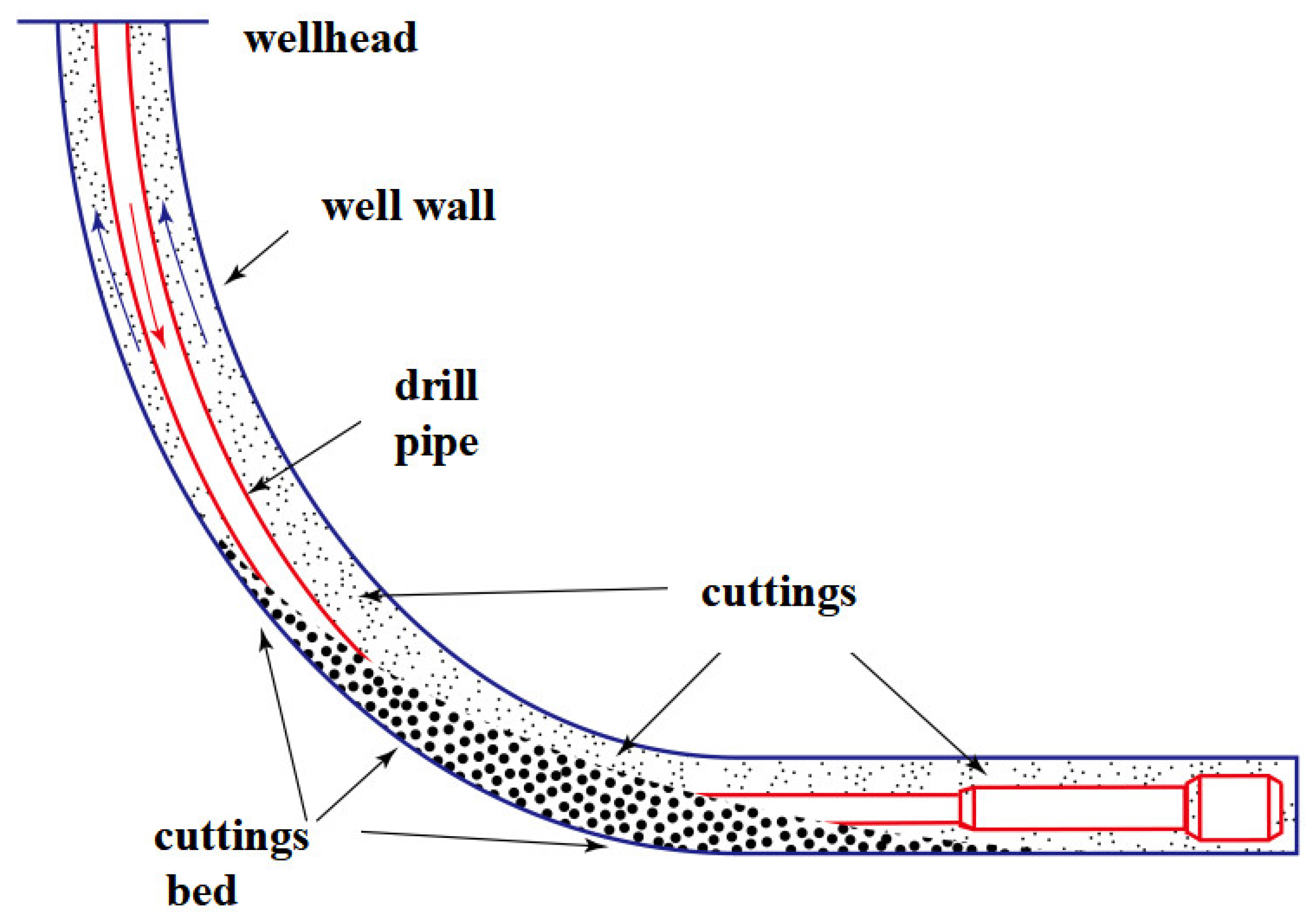
Figure 2.
Schematic diagram for force analysis during particle sedimentation (mainly influenced by fluid drag, buoyancy and gravity).
Figure 2.
Schematic diagram for force analysis during particle sedimentation (mainly influenced by fluid drag, buoyancy and gravity).

Figure 3.
Schematic diagram of sedimentation resistance coefficient CD and sedimentation velocity Vs as calculated using the Newton iteration method.
Figure 3.
Schematic diagram of sedimentation resistance coefficient CD and sedimentation velocity Vs as calculated using the Newton iteration method.
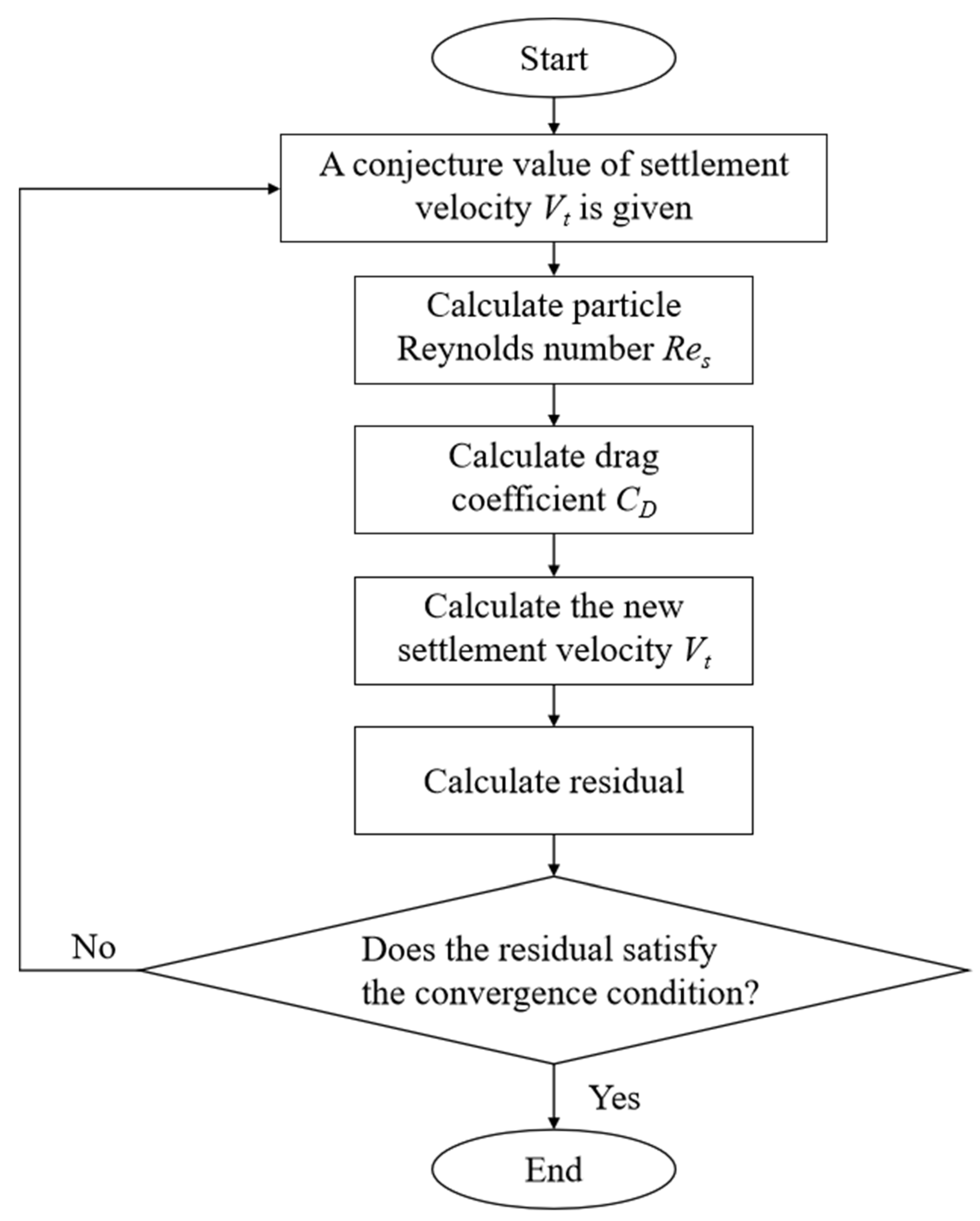
Figure 4.
Schematic diagram of the particle sedimentation experimental device [18].
Figure 4.
Schematic diagram of the particle sedimentation experimental device [18].
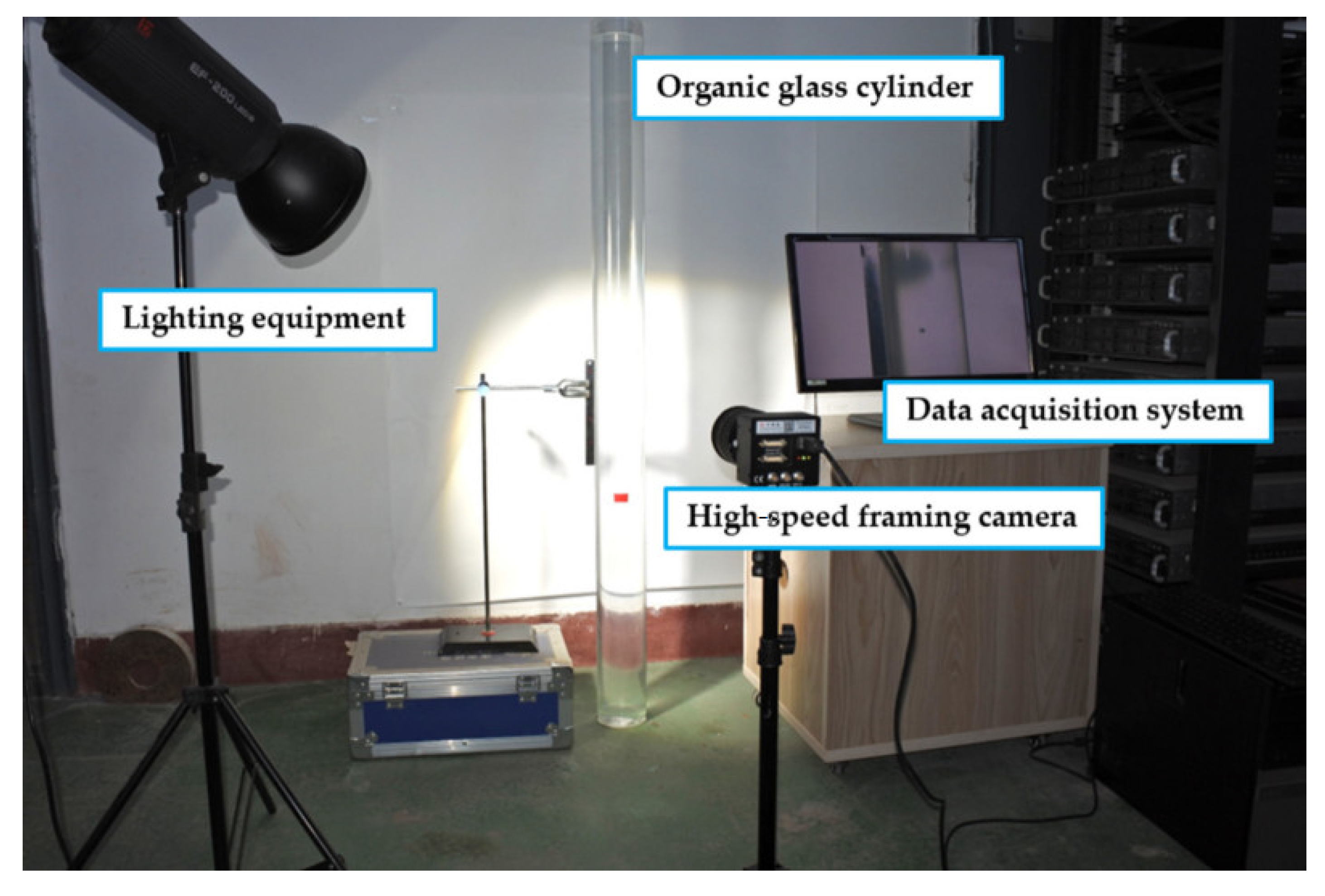
Figure 5.
Parallel plates with different widths [41].
Figure 5.
Parallel plates with different widths [41].

Figure 6.
Schematic diagram of shale cuttings’ morphology in different well sections.


Table 1.
A few representative CD-Res correlations for spherical particles in Newtonian fluid.
| Author | CD-Res Relationship | Range of Application |
|---|---|---|
| Schiller and Naumann [21] | ||
| Haider and Levenspiel [22] | ||
| Cheng [23] | ||
| Abraham [24] | ||
| Clift [25] | ||
| Brown [26] | ||
| Terfous [27] | ||
| Roos [28] |
Table 2.
Some representative wall coefficient calculation models of spherical particles settling in cylindrical Newtonian fluid.
Table 2.
Some representative wall coefficient calculation models of spherical particles settling in cylindrical Newtonian fluid.
| Author | Wall Factor Relationship | Applicable Region |
|---|---|---|
| Munroe [31] | Turbulent flow | |
| Francis [32] | Laminar flow | |
| Fidleris [33] | Graphic method | All ranges |
| Felice [34] | Transition region and turbulence | |
| Kehlenbeck [35] | Transition region | |
| Haberman [36] | Laminar flow |
where λ means the proportion of the particle diameter d to the pipe diameter D. The above studies show that the wall element of particle settling in Newtonian fluid is only associated with the particle diameter d and pipe diameter D in laminar and turbulent regions. In the transition region, the wall element is affected by both λ and particle Reynolds number Res.
Table 3.
A few representative CD-Res calculation models for spherical particles settling in non-Newtonian fluid.
Table 3.
A few representative CD-Res calculation models for spherical particles settling in non-Newtonian fluid.
| Author | CD-Res Relationship | Sphere of Application |
|---|---|---|
| Khan and Richadson [54] | ||
| Kelessidis and Mpandelis [59] | ||
| Renaud [60] | ||
| Shah [61] | ||
| Machac [62] | ||
| Okesanya [63] |
Table 4.
Sphericity of particles.
| Particle Shape | Spherical Degree | Particle Shape | Spherical Degree |
|---|---|---|---|
| Sphere | 1.0 | Polygon | 0.8~0.65 |
| Spherical | 1.0~0.8 | Long strip | 0.65~0.5 |
| Flat | <0.5 | Cube | 0.806 |
| Flat | 0.671 | Cylinder (height = diameter) | 0.877 |
| Cylinder (diameter:high = 1:10) | 0.580 | Circular plate (diameter:thickness = 1:10) | 0.472 |
Table 5.
A few representative models for calculating sedimentation velocity based on particle volume concentration.
Table 5.
A few representative models for calculating sedimentation velocity based on particle volume concentration.
| Author | Wall Factor Relationship |
|---|---|
| Aziz [90] | |
| Nolte [91] | |
| Daneshy [92] | |
| Richardson [93] | |
| Maude [94] |
where is the particle volume coefficient, dimensionless; is the settling velocity under the volume fraction of particle, m/s; is Stokes’ settling velocity, m/s; and is the correction coefficient obtained from the experiment, with under laminar flow conditions, and under turbulent conditions, is between 2 and 4.
Disclaimer/Publisher’s Note: The statements, opinions and data contained in all publications are solely those of the individual author(s) and contributor(s) and not of MDPI and/or the editor(s). MDPI and/or the editor(s) disclaim responsibility for any injury to people or property resulting from any ideas, methods, instructions or products referred to in the content. |
© 2023 by the authors. Licensee MDPI, Basel, Switzerland. This article is an open access article distributed under the terms and conditions of the Creative Commons Attribution (CC BY) license (https://creativecommons.org/licenses/by/4.0/).
Share and Cite
MDPI and ACS Style
Hou, Z.; Yuan, Y.; Chen, Y.; Jiang, E.; Wang, H.; Zhang, X. A Review of the Settling Law of Drill Cuttings in Drilling Fluids. Processes 2023, 11, 3165. https://doi.org/10.3390/pr11113165
AMA Style
Hou Z, Yuan Y, Chen Y, Jiang E, Wang H, Zhang X. A Review of the Settling Law of Drill Cuttings in Drilling Fluids. Processes. 2023; 11(11):3165. https://doi.org/10.3390/pr11113165
Chicago/Turabian StyleHou, Zhaokai, Yuan Yuan, Ye Chen, Enyuan Jiang, Huaishan Wang, and Xu Zhang. 2023. "A Review of the Settling Law of Drill Cuttings in Drilling Fluids" Processes 11, no. 11: 3165. https://doi.org/10.3390/pr11113165
Note that from the first issue of 2016, this journal uses article numbers instead of page numbers. See further details here.