Article

Research on the Hydraulic Excitation Characteristics of the Top Cover Caused by the Radial Installation Deviation of the Seal of a 1GW Francis Turbine

1
China Three Gorges Construction Engineering Corporation, Chengdu 610041, China
2
Department of Energy and Power Engineering, Tsinghua University, Beijing 100084, China
3
School of Energy and Power Engineering, Jiangsu University, Zhenjiang 212013, China
4
S.C.I. Energy, Future Energy Research Institute, Seidengasse 17, 8706 Zurich, Switzerland
*
Author to whom correspondence should be addressed.
Processes 2023, 11(11), 3172; https://doi.org/10.3390/pr11113172
Submission received: 28 September 2023 / Revised: 25 October 2023 / Accepted: 27 October 2023 / Published: 7 November 2023
(This article belongs to the Special Issue State-of-the-Art Energy Conversion and Storage)

Abstract

:
The radial installation deviation of the turbine runner will change the gap flow between the upper crown and the lower ring seal, which will affect the radial force of the runner and the hydraulic excitation characteristics of the top cover. This research focuses on the 1GW Francis turbine on the right bank of the Baihetan hydropower station. The pressure distribution along the circumference of the top cover was analyzed, and the effects of deviations on the specific generation of hydraulic excitation forces were studied. This research shows that the increase in radial deviation will slightly reduce the output and efficiency, and the radial force on the runner increases parabolically. When the radial deviation is 1.5 mm, the radial force is 5.9 times higher compared to the case without any deviation, and the radius of the fitting circle of the radial force behavior trajectory increases with the increase in radial deviation. In addition, the radial deviation has little effect on the internal flow of the runner and the pressure distribution in the upper crown chamber. The dominant frequency components at the upstream monitoring points include fn, 15 fn, 24 fn, and 30 fn. The dominant frequency components at the downstream monitoring points include the blade passing frequencies of 15 fn and 30 fn. However, with the increase in radial deviation, the fluctuation amplitudes exhibit an asymmetric distribution, the uniformity of the pressure distribution in the circumferential direction of the labyrinth seal area becomes significantly worse, and the waveform of the downstream monitoring points changes significantly and presents a non-uniform distribution in one rotation cycle.

1. Introduction

Hydropower, as a renewable and clean energy source, serves as a cornerstone of the low-carbon power industry, providing strong impetus for sustainable economic and social development and playing a vital role in promoting carbon peaking and carbon neutrality [1]. The Baihetan hydropower station, ranking second only to the Three Gorges Dam, is the world’s second largest hydropower station and boasts a leading single-unit capacity globally, with an annual average power generation of 62.443 billion kilowatt-hours. The safe and stable operation of the Baihetan hydropower unit is crucial to ensure smooth power generation. Hydraulic excitation, as a key factor for the safe and stable operation of turbine–generator units, has gradually gained attention in engineering practice. To meet the growing demand for hydropower generation, the size and scale of Francis turbines have been continuously enlarged, resulting in an increase in clearance between the runner and fixed components and causing certain volumetric losses [2]. The installation deviation of the turbine runner can alter the clearance size and impact the fluid flow of the upper crown and lower ring seals. Among them, the upper crown seal is a critical region for flow throttling and pressure reduction in the upper crown chamber, and it is also the most sensitive location to radial installation deviations. The fluid flow pattern and pressure distribution within the upper crown chamber directly influence the radial forces exerted on the runner and the hydraulic excitation characteristics experienced by the top cover, thereby significantly affecting the operational stability of the turbine–generator unit [3,4,5].
In recent years, domestic and international scholars have conducted more in-depth research on pressure pulsation and hydraulic excitation in hydraulic turbine units, providing theoretical guidance for improving the operational stability of these units. Pressure pulsation is an important factor affecting the stable operation of turbine units. Wang et al. [6] conducted numerical simulations using the RANS–LES method to study the vortex rope and pressure pulsation distribution in the draft tube of a Francis turbine under different operating speeds. Chen et al. [7] performed numerical simulations on a Francis turbine without guide vane adjustments to obtain the distribution of internal pressure pulsation and flow characteristics within the turbine unit. Yu et al. [8] conducted numerical simulations on a pump-turbine under different non-design operating conditions and studied the correlation between draft tube vortex evolution and low-frequency pressure pulsation. The study indicated that the frequency of pressure pulsation during cavitation is influenced by the evolution of cavitation volume. Trivedi et al. [9] investigated the impact of flow rate and velocity changes on the pressure pulsation amplitude in the draft tube, runner, and vaneless region by studying power increase and decrease scenarios. Ji et al. [10] studied the flow characteristics of a Francis turbine draft tube under different outputs by numerical simulation. And laser Doppler velocimetry (LDV) tests were conducted to test the flow characteristics of the draft tube of the Francis turbine model.
Installation deviation is an unavoidable issue during the installation process of a hydraulic turbine unit, and its presence can affect the overall operation of the unit. Ji et al. [11] conducted research on the influence of thrust bearing installation deviation on the flow performance of the thrust bearing oil film using fluid–structure coupling and computational fluid dynamics (CFD). Wang et al. [12] investigated the influence of the upper crown seal gap value on the pressure cavity flow field between the upper crown seal gap chamber, top cover, and upper crown in a mixed-flow pump-turbine. The study showed that the average pressure in the pressure cavity below the top cover increases with the increase in the upper crown seal gap value, and the axial force also changes with the increase in the seal gap. Liu et al. [13] studied the influence of different axial installation deviations on axial hydraulic thrust, showing that axial installation deviation has a significant impact on the axial hydraulic thrust on the outer surface of the upper crown and lower ring but has little effect on the axial hydraulic thrust on the runner flow passage and inner surface. Wu et al. [14] performed simulation calculations on a model of a mixed-flow turbine with five different lower ring gaps and found that the influence of the lower ring gap on the flow field and efficiency varies under different flow conditions. Acharya et al. [15] studied the development of the leakage vortex in the guide vane gap of a Francis turbine and the resulting pressure pulsation. They conducted spectral analysis of pressure pulsation in the vaneless space, runner blades, and draft tube, observing a peak of pressure pulsation and its harmonics.
It is evident that installation deviations can affect the pressure pulsation characteristics and hydraulic excitation characteristics of the turbine. This can potentially result in turbine vibration and noise, thereby impacting the safe and stable operation of the turbine. Therefore, the research of installation deviations’ influence on hydraulic excitation has practical engineering significance. In this research, numerical calculations were conducted for five types of installation deviation positions in the Francis turbine. This research investigated the effects of installation deviations on the turbine’s efficiency, radial forces, and other external characteristics. Additionally, the specific effects of deviations on the generation of hydraulic excitation forces were studied by analyzing the time-domain and frequency-domain signals of pressure fluctuations at monitoring points on the top cover.

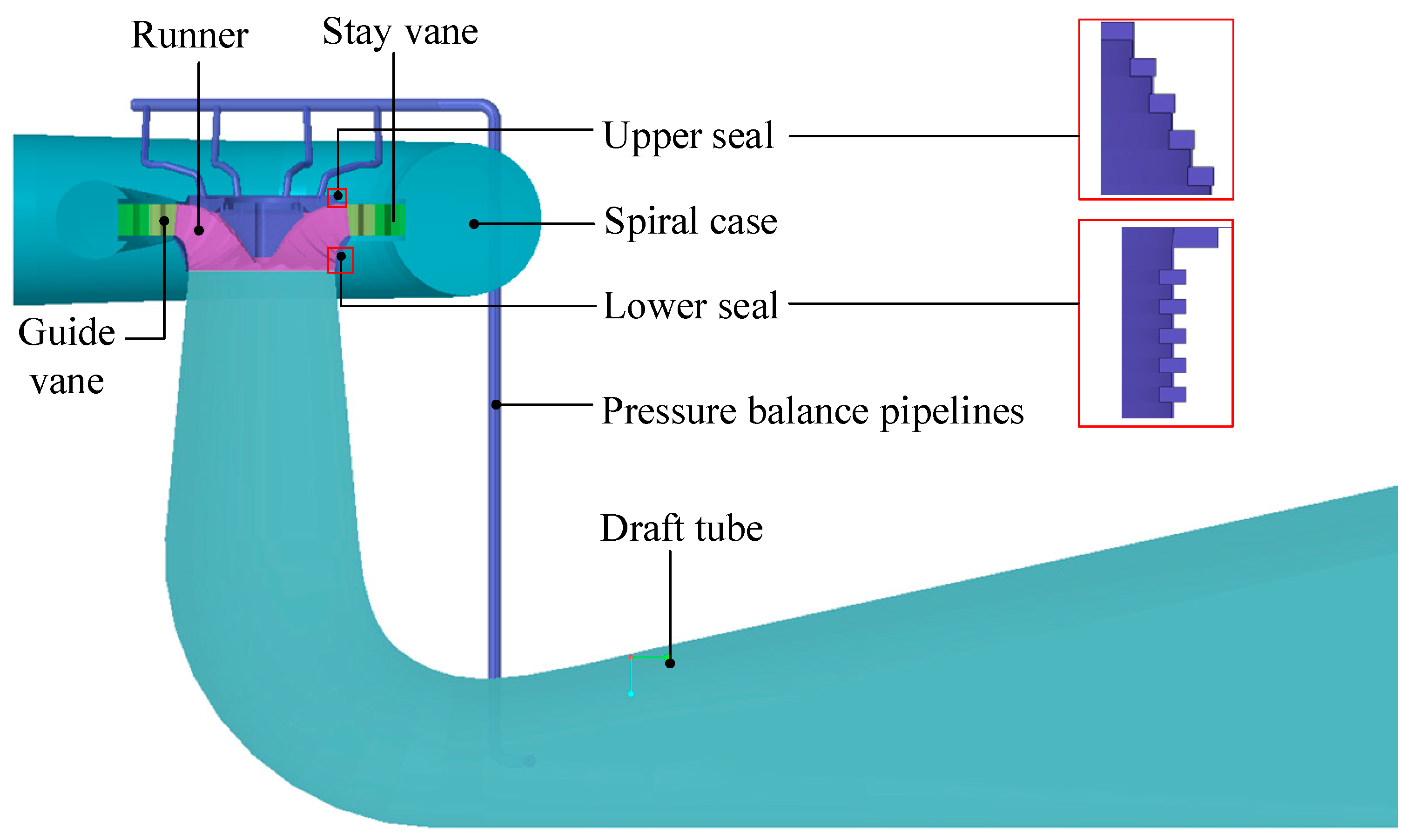
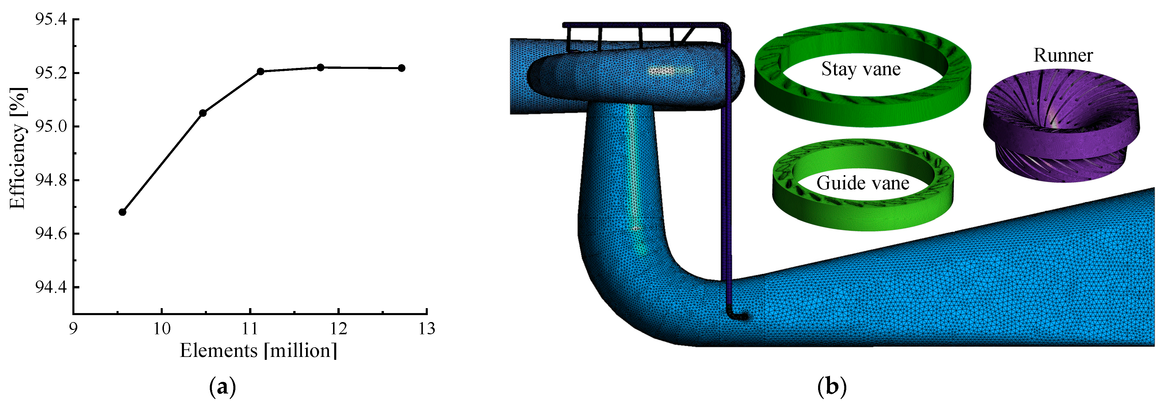
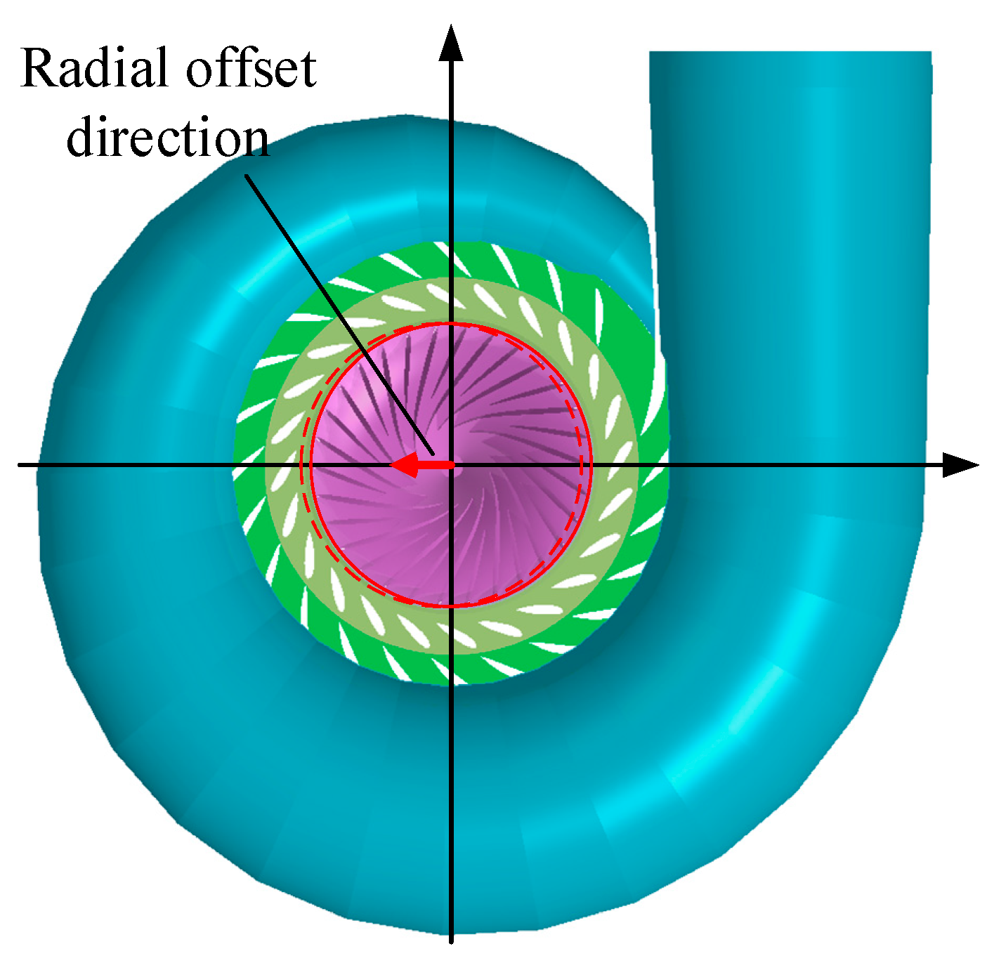
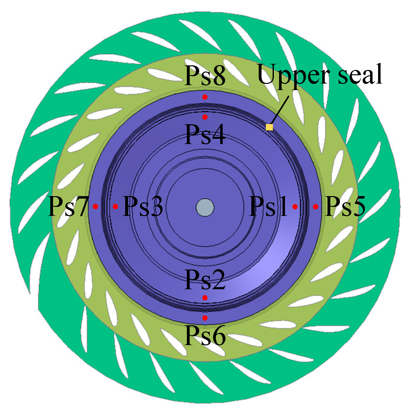
2. Materials and Methods

The subject of this research is the right-bank unit of the Baihetan hydropower station, which uses a Francis turbine with a rated head of 202.1 m, a rated flow of 538.8 m3/s, a rated speed of 107.1 r/min, and a rated output of 1015 MW. The basic geometric parameters of the unit are shown in Table 1. A three-dimensional software, CREO, was used to model the Francis turbine, and the computational domain of the flow field includes the spiral case, stay vanes, guide vanes, runner, upper crown chamber, lower ring chamber, upper and lower seals, pressure balance pipelines (PBP), runner cone, and draft tube, as shown in Figure 1. The upper crown chamber is composed of the top cover and the upper crown to form a flow channel to prevent overflow. The top cover can also support the guide vanes, transmission mechanism, and operating mechanism of the unit, as well as supporting the guide bearings. Leakage from the gap between the upper and lower seals not only causes volume loss in the Francis turbine but also affects the radial force and axial thrust of the runner. This research mainly focuses on the relative installation deviation between the top cover and the runner, which can cause uneven distribution of the gap between the upper and lower seals, directly affecting the axial thrust and radial force on the runner and the hydraulic excitation characteristics inside the upper crown chamber.
In this research, ICEM was used to grid the computational domain of the Francis turbine. The specific griding results are shown in Figure 2. The guide vane was grided using a hexahedral-structured grid, while the rest of the fluid domains were grided using an unstructured grid. Grid refinement was applied at the boundaries of each component.
Five sets of grid schemes were established to validate the grid independence, as shown in Figure 2a. As the number of grids increased, the efficiency of the Francis turbine reached a stable level. To reduce computation time while still ensuring accuracy, the fourth grid scheme was selected [16]. The number of grids for the spiral case, stay vane, guide vane, runner, upper crown and lower ring chambers, pressure balance pipelines, runner cone, and draft tube were 1.307 million, 259,000, 439,000, 6.123 million, 569,000, 168,000, 1.211 million, and 1.745 million, respectively. The total number of grids was 11.822 million, as shown in Figure 2b.
This research used ANSYS CFX to conduct numerical simulations of the rated operating conditions of a Francis turbine, focusing on the investigation of radial installation deviations between the top cover and runner. This part primarily studied the flow field variations caused by radial installation deviations and the sources and characteristics of hydraulic excitations acting on the top cover, and analyzed the sensitivity of the unit’s operational performance to the deviation magnitude. As shown in Figure 3, steady and unsteady calculations are carried out for five cases: no installation deviation, X-direction installation deviation of ΔX = 0.5 mm, ΔX = 1.0 mm, and ΔX = 1.5 mm, and Y-direction installation deviation of ΔY = 0.5 mm. When there is no installation deviation, the unilateral clearance between the upper crown chamber and the lower ring chamber seal is 3.3 mm. Eight pressure monitoring points were set up at the top cover. Among them, the monitoring points Ps1–Ps4 were located downstream of the upper crown seal and were evenly distributed at 360 degrees. Ps5–Ps8 were located upstream of the upper crown seal and were evenly distributed at 360 degrees, as shown in Figure 4. The numerical model uses the SST k-ω turbulence model. The reference pressure is set to 1 atm. The inlet and outlet boundary conditions are set to the inlet total pressure and the outlet static pressure, respectively. The standard wall function is used for the near wall, and the wall condition is set to the no-slip wall. The convergence accuracy of the calculation is set to 10−4.

3. Results

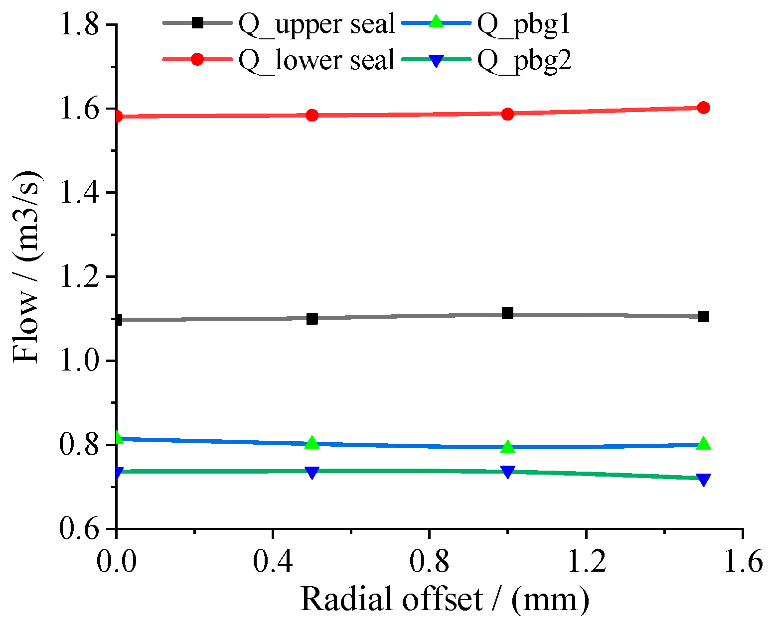
3.1. Effect of Radial Deviation on the External Characteristics of the Francis Turbine

By keeping the guide vane opening constant at the rated opening, the computational results of four cases were analyzed: no installation deviation on the runner, as well as deviations of ΔX = 0.5 mm, ΔX = 1.0 mm, and ΔX = 1.5 mm. Firstly, the influence of different radial installation deviations on the external characteristics of the Francis turbine at the rated operating condition was studied. The main external characteristic indicators involved the output, efficiency, leakage flow rate from the upper crown and lower ring seals, and the flow rate in two balance pipelines. Figure 5 shows the efficiency and output of the Francis turbine for different radial deviations of the runner. It can be observed that with an increase in radial installation deviation, both the output and efficiency of the water turbine decrease. Specifically, when the installation deviation is 1.5 mm, compared to the case with no installation deviation, the efficiency decreases by 0.023% and the output decreases by 0.93 MW. Therefore, the radial installation deviation of the runner has a certain impact on the external characteristics of the Francis turbine.
When the runner is radially offset, the top cover and the upper crown of the runner together constitute the flow passage, and the flow area is unchanged. However, the shape of the flow passage changes, especially at the sealing positions of the upper crown chamber and the lower chamber. When the radial offset is ΔX = 0.5 mm, ΔX = 1.0 mm, and ΔX = 1.5 mm, the change rates of the single-sided gap in the seal are 15.2%, 30.3%, and 45.5%, respectively. Therefore, the radial installation deviation of the runner has a great influence on the fluid flow at the sealing position of the upper crown and the lower ring, especially as the sealing is the most critical position for throttling between the upper crown chamber and the runner cone. Figure 6 shows the leakage of the upper crown and lower ring seals and the flow rates in the two balance pipelines under different radial installation deviations of the runner. It can be observed that as the radial installation deviation increases, the leakage at the upper crown and lower ring seals slowly increases (with a leakage change of +0.7% at ΔX = 1.5 mm, indicating minimal impact), while the flow rate in the two pressure balance pipelines decreases slowly (with a leakage change of −2.2% at ΔX = 1.5 mm, also indicating minimal impact).
Figure 7 illustrates the radial forces acting on the runner under different radial installation deviations and the distribution of radial forces during one rotation cycle. It can be observed that as the radial installation deviation increases, the radial forces acting on the runner increase in a parabolic manner, with the direction of the radial force shifting toward the nose of the spiral case. When there is no installation deviation, the radial force on the runner is minimal. However, when the radial installation deviations are 0.5 mm, 1.0 mm, and 1.5 mm, the radial forces are 2.1 times, 3.7 times, and 5.9 times greater than that with no installation deviation, respectively. In other words, at ΔX = 1.5 mm, the radial force reaches 43.5 tons. From Figure 7a, it can be observed that the radial force on the runner mainly shifts toward the Y-direction, especially when the installation deviation increases, as this tendency becomes more pronounced. It can also be seen that the trajectory of the radial force is essentially circular, and as the radial deviation increases, the range of variation in the radial force (represented by the fitted circle’s radius FR1) gradually increases. Specifically, when the installation deviations are 0.0 mm, 0.5 mm, 1.0 mm, and 1.5 mm, the corresponding FR1 values are 8.34 tons, 10.02 tons, 14.86 tons, and 20.06 tons, respectively.

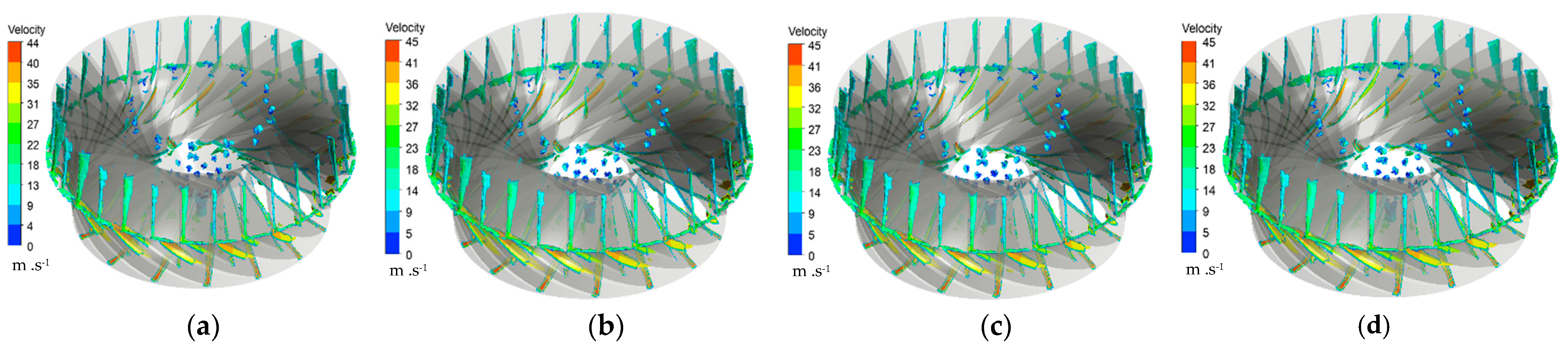
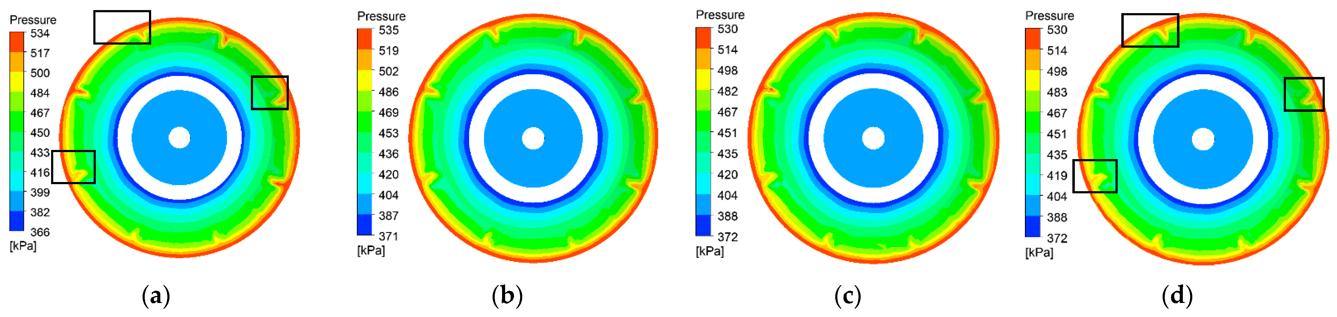
3.2. Influence of Radial Deviations on the Internal Flow Characteristics and Pressure Distribution of the Top Cover

In order to further analyze the influence of radial installation deviation on the internal flow field of the runner, the distribution of vortex structures inside the runner is studied for five different cases: ΔX = 0.0 mm, ΔX = 0.5 mm, ΔX = 1.0 mm, and ΔX = 1.5 mm. The Q-criterion is used to identify the vortex cores inside the runner [17,18,19]. Appropriate thresholds are chosen to ensure the clarity of the main vortex structure and capture the smaller vortices as much as possible. Figure 8 represents the isopleth surface of Q = 500 s−2, and the vortex structures are rendered using absolute velocity. It can be observed that the main vortex cores inside the runner are clearly defined and evenly distributed at the leading edge and trailing edge of the runner blades, as well as at the drain holes. There is no blade vortex present inside the runner. Comparing the shape of the vortex and the velocity distribution on the isopleth surfaces at the leading edge, trailing edge, and drain holes of the runner for different radial installation deviations, it can be concluded that the vortex core structures and their sizes remain essentially the same. It can be seen that the installation deviation has almost no impact on the flow field structure inside the runner.
The contact area between the top cover and the fluid in the flow passage mainly includes the fluid inside the guide vane’s hub surface and the fluid inside the discharge cone. The function of the top cover seal is to throttle and reduce the pressure of the fluid in the upper crown chamber. Therefore, it is necessary to analyze the pressures acting on the upstream and downstream sides of the top cover seal. Figure 9 shows the pressure distribution in the upstream region of the top cover seal for different installation deviations. It can be observed that the pressure gradually decreases after the fluid enters the guide vane, and there is a sudden pressure drop when the fluid enters the vaneless area of the upper crown chamber. The pressure distribution in the upstream region of the seal remains basically the same for different installation deviations. Figure 10 shows the pressure distribution in the downstream region of the top cover seal for different installation deviations. It can be seen that there is a sudden pressure drop after the fluid passes through the seal, and the pressure reduction effect of the seal is basically the same for different radial deviations. The maximum pressure in the downstream region is 530–535 kPa. However, as the radial installation deviation increases, the uniformity of the pressure distribution at the inlet of the downstream region deteriorates (marked by the black box).
The top cover seal is the most critical area for throttling and pressure reduction in the upper crown chamber, and it is also the most sensitive area when radial deviation occurs in the upper crown chamber. According to the calculations in Section 3.1, it is known that radial installation deviation has a significant impact on the radial force of the runner. The seal area between the top cover and the lower ring chamber is the region with the largest axial projection. Therefore, the variation in radial force on the rotating wheel is mainly caused by the uneven pressure distribution in the seal area. In order to quantify the pressure pulsations in the seal area more precisely, the pressure fluctuation amplitude ΔP is used to represent the circumferential variation of pressure [20,21]. The expression for ΔP is as follows:
Δ P = P 1 n i = 1 n P i
where ΔP represents the difference between the pressure at the monitoring point, Pa, and the average pressure, Pi.
Figure 11 shows the pressure distribution of the upper seal in the circumferential direction for different radial installation deviations. Monitoring lines, namely Monitoring I, Monitoring II, Monitoring III, Monitoring IV, and Monitoring V, are set on the five sealing teeth of the top cover seal. It can be observed that with the increase in radial installation deviation, the uniformity of the pressure distribution in the circumferential direction significantly deteriorates. The pressure fluctuation range on Monitoring Line I remains consistent for different installation deviations. However, as the fluid enters the second, third, fourth, and fifth sealing teeth (Monitoring II, Monitoring III, Monitoring IV, and Monitoring V), the uniformity of the pressure distribution in the circumferential direction gradually worsens. Among them, for installation deviations of 0.0 mm, 0.5 mm, 1.0 mm, and 1.5 mm, the maximum pressure differences in the circumferential direction for the fourth and fifth sealing teeth are 10 kPa, 20 kPa, 40 kPa, and 70 kPa, respectively. This corresponds to the variation pattern of the radial force on the runner shown in Figure 10a. When there is no installation deviation, the radial force exerted on the top cover is small. However, as the installation deviation increases, the radial force exerted on the top cover is basically consistent with the radial force exerted on the runner.

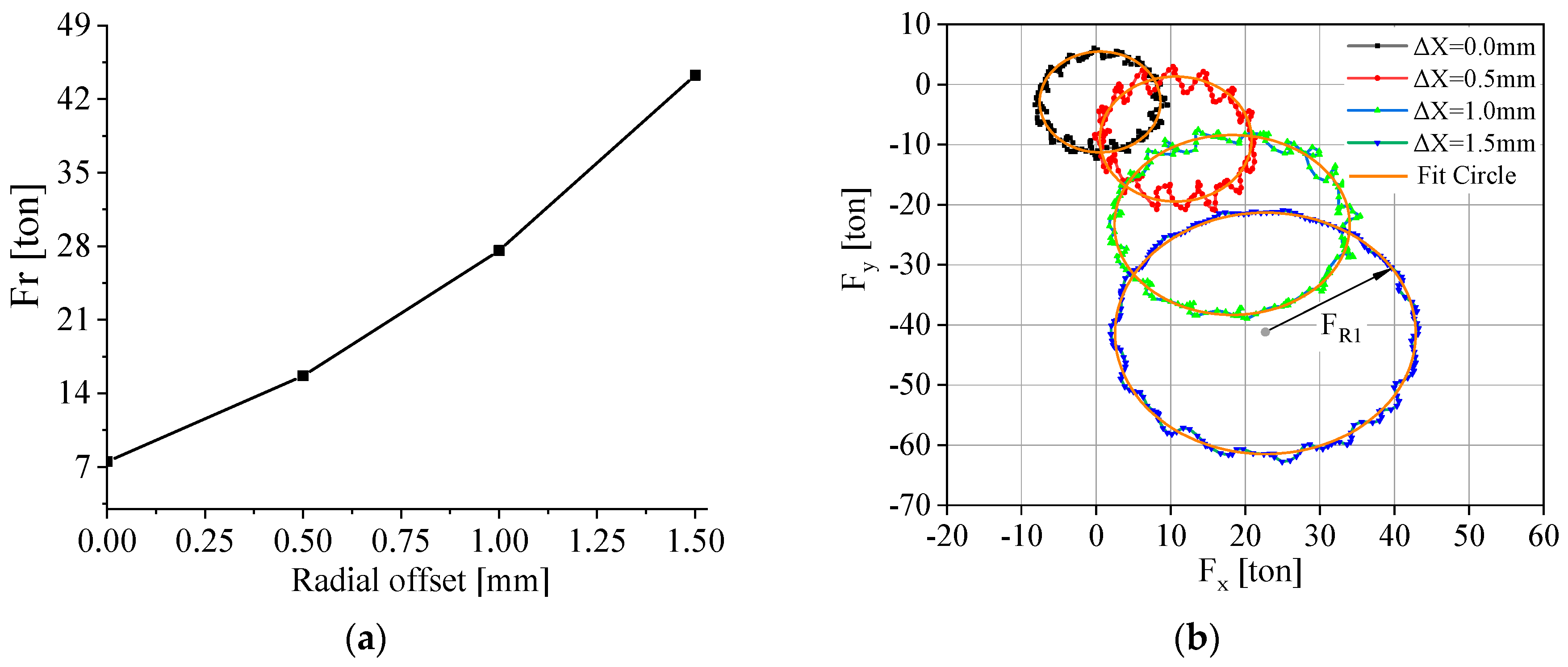
3.3. Distribution of Hydraulic Excitation Force by Different Radial Deviations

From the above analysis, it can be concluded that the radial installation deviation of the runner has a significant impact on the pressure distribution on the top cover and the radial force. In order to analyze the unsteady-state hydraulic excitation force on the top cover, the pressure fluctuations in different areas of the top cover are monitored. Four monitoring points are set uniformly upstream of the upper crown seal, and four monitoring points (Ps5–Ps8) are set uniformly downstream of the upper crown seal.
Figure 12 shows the time-domain waveform of the pressure fluctuations at monitoring points Ps1–Ps8 on the top cover for different radial installation deviations. It can be observed that the waveforms of monitoring points Ps1–Ps4 are basically consistent for all installation deviation conditions, and the waveforms of monitoring points Ps5–Ps8 are also basically consistent. As the radial installation deviation increases, the waveforms of monitoring points Ps1–Ps4 significantly change, and the distribution within one rotation cycle becomes non-uniform. On the other hand, the waveforms of monitoring points Ps5–Ps8 show 15 large peaks and valleys and 15 small peaks and valleys. Specifically, for installation deviations of 0.0 mm, 0.5 mm, 1.0 mm, and 1.5 mm, the corresponding peak-to-peak values at the downstream monitoring points are 1.34 kPa, 0.90 kPa, 0.89 kPa, and 1.08 kPa, respectively. The corresponding peak-to-peak values at the upstream monitoring points are 21.6 kPa, 23.2 kPa, 23.3 kPa, and 22.3 kPa, respectively.
In order to further analyze the main factors affecting the hydraulic excitation force on the top cover, the time-domain signals of the monitored pressure fluctuations are subjected to FFT transformation to analyze the amplitude and frequency characteristics of the pressure fluctuations, as shown in Figure 13. When there is no installation deviation, the main frequency components at monitoring points Ps1–Ps4 include fn, 15 fn, 24 fn, and 30 fn. The maximum pressure fluctuation amplitudes at each monitoring point are in the order of Ps1 > Ps3 > Ps4 > Ps2. The main frequency components at monitoring points Ps5–Ps8 include 15 fn and 30 fn. The maximum pressure fluctuation amplitudes at each monitoring point are in the order of Ps5 > Ps7 > Ps8 > Ps6. Here, 15 fn and 30 fn represent the passing frequencies of the rotating wheel blades. The maximum amplitude of pressure fluctuation for Ps1–Ps4 is 0.2548 kPa, and for Ps5–Ps8, it is 7.64 kPa. When there is an installation deviation in the runner, the main frequencies at monitoring points Ps1–Ps4 remain unchanged. The amplitude of the frequency component at 24 fn significantly decreases with the increasing installation deviation, while the pressure fluctuation amplitudes at frequencies of 15 fn and 30 fn slightly decrease. The main frequencies at monitoring points Ps5–Ps8 also remain unchanged. The amplitudes at a frequency of 15 fn range from 4.8 kPa to 5.4 kPa, and the amplitudes at a frequency of 30 fn range from 7.0 kPa to 7.8 kPa. It can also be observed that with the increasing installation deviation, the fluctuation amplitudes at monitoring points Ps5–Ps8 exhibit an asymmetric distribution, but no fn component caused by radial installation deviation occurs.

4. Conclusions

When there is a radial installation deviation in the Francis turbine, it mainly affects the fluid flow at the positions of the upper crown and lower ring seals. Among them, the upper crown seal is the most critical area for pressure reduction in the upper crown chamber and the most sensitive area when radial deviation occurs. The flow regime and pressure distribution in the upper crown chamber directly affect the hydraulic excitation characteristics on the top cover. This study provides a theoretical reference for the subsequent vibration research of the whole unit. The subsequent vibration of the unit can be carried out around the hydraulic excitation force generated by the installation deviation.
  • As the radial installation deviation increases, the output and efficiency of the Francis turbine both show a decreasing trend. The leakage at the upper crown and lower ring seals slightly increases, while the flow in the pressure balance pipelines decreases slightly. With the increase in radial installation deviation, the radial force acting on the runner increases in a parabolic manner. The radial force is shifted to the direction near the nose of the spiral case.
  • Under different radial installation deviations, the installation deviation has little effect on the flow field structure inside the runner, and the pressure distribution in the hub surface of the guide vanes in contact with the top cover and the upper crown chamber is basically consistent. The uniformity of the pressure distribution in the labyrinth seal area in the circumferential direction deteriorates significantly with the increase in radial installation deviation, which is the main reason for the increased radial force acting on the runner.
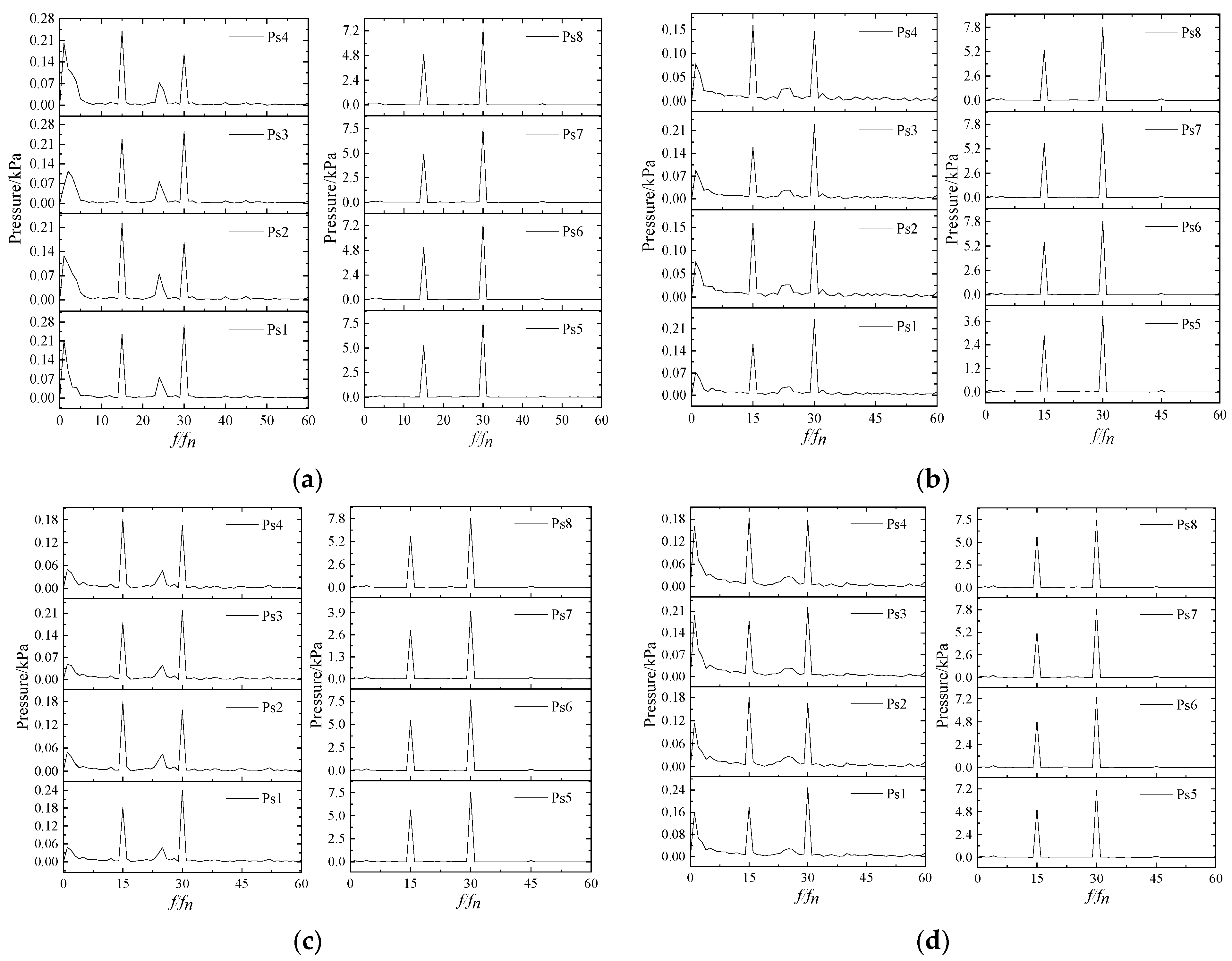
  • With the increase in radial installation deviation, there are significant changes in the waveform of the downstream monitoring point of the labyrinth seal. The waveform of the upstream monitoring point, on the other hand, exhibits 15 large peaks and valleys and 15 small peaks and valleys. The dominant frequency components of the upstream monitoring points include fn, 15 fn, 24 fn, and 30 fn. The dominant frequency components of the downstream monitoring points include 15 fn and 30 fn, and there is no fn component caused by radial installation deviation.

Author Contributions

Conceptualization, K.J. and Y.L.; methodology, Y.L. and P.L.; software, Z.Z.; validation, J.L., Y.Z. and X.H.; formal analysis, Y.L.; investigation, K.J. and J.L.; resources, Z.W.; data curation, P.L.; writing—original draft preparation, Y.L. and Z.Z.; writing—review and editing, Y.L. and K.J.; supervision, Z.W.; project administration, Z.W.; funding acquisition, Z.W. All authors have read and agreed to the published version of the manuscript.

Funding

This study was supported by the Three Gorges Construction Group Co., Ltd. (Contract No. JGJD0322003), the China Postdoctoral Science Foundation Funded Project (2021M701847), the China Postdoctoral Science Foundation Funded Project (2022M711768), the Natural Science Foundation of Jiangsu Province (BK20210771), and the Fund Program of State Key Laboratory of Hydroscience and Engineering (No. 2022-KY-06).

Data Availability Statement

The data that support the findings of this study are available within the article.

Conflicts of Interest

The authors declare no conflict of interest.

Nomenclature

Z1Blade number of stay vaneFrRadial force of the runner, ton
Z2Blade number of guide vaneFxX-direction radial force, ton
Z3Blade number of runnerFyY-direction radial force, ton
D1Runner inlet diameter, mmFR1Fitted circle’s radius, ton
D2Runner outlet diameter, mmΔPVariation of pressure, Pa
b1Runner inlet width, mmPiPressure value, Pa
ΔXX-direction installation deviation, mmPBPPressure balance pipelines
ΔYY-direction installation deviation, mmCFDComputational fluid dynamics
QFlow rate, m3/sSSTShear Stress Transport

References

  1. Zhang, Z.L.; Liu, B.; Wang, F.Q. Innovation and Development of Conventional Hydropower and Pumped-storage Technology in China. Water Power 2023, 1–7. [Google Scholar]
  2. Zhang, X.Y. Analysis on Structure of Leakage-check Ring and Decompression Device of Upper Runner Crown. Heilongjiang Hydraul. Sci. Technol. 2023, 51, 47–50. [Google Scholar]
  3. Ma, W.; Liang, W.K.; Nan, H.P.; Zhao, D.L.; Li, J.B.; Dong, Y.T. The influence of sealing clearance value of Francis runner on the unit stability. J. Hydroelectr. Eng. 2010, 29, 219–223. [Google Scholar]
  4. Zhou, X.; Wu, H.G.; Su, K. Overview and discussion on hydraulic axial thrust in Francis turbine research. J. Hydraul. Eng. 2019, 50, 1242–1252. [Google Scholar]
  5. Dong, Y.T.; Liang, W.K. Numerical Simulation on the Francis Hydraulic Turbine Runner’s Sealing Device and Relief Pipes. J. Xi’an Univ. Technol. 2008, 2, 1006–4710. [Google Scholar]
  6. Wang, T.T.; Zhang, C.B.; Xie, T.T.; Cao, W.Z. Analysis on vortex ropes and pressure pulsations in draft tube of variable-speed Francis turbine. J. Hydroelectr. Eng. 2021, 40, 95–101. [Google Scholar]
  7. Chen, H.; Lu, Y.G.; Liu, K.; Zhang, Z.Z.; Li, H.H.; Huang, X.X.; Zhao, W.Q.; Wang, Z.W. Study on the Internal Flow Characteristics of Long and Short Blade Runners of a 1000 MW Francis Turbine under Different Opening Conditions. Processes 2023, 11, 1796. [Google Scholar] [CrossRef]
  8. Yu, A.; Wang, Y.; Tang, Q.; Lv, R.; Yang, Z. Investigation of the vortex evolution and hydraulic excitation in a pump-turbine operating at different conditions. Renew. Energy 2021, 171, 462–478. [Google Scholar] [CrossRef]
  9. Trivedi, C.; Agnalt, E.; Dahlhaug, O.G. Experimental study of a Francis turbine under variable-speed and discharge conditions. Renew. Energy 2018, 119, 447–458. [Google Scholar] [CrossRef]
  10. Ji, L.; Xu, L.; Peng, Y.; Zhao, X.; Li, Z. Experimental and numerical simulation study on the flow characteristics of the draft tube in Francis turbine. Machines 2022, 10, 230. [Google Scholar] [CrossRef]
  11. Ji, Z.; Shi, Y.; Da, X.; Cao, J.; Gong, Q.; Wang, Z.; Huang, X. Influence of Installation Deviation of Thrust Bearing on Oil Film Flow of 1000 MW Hydraulic Turbine Unit. Water 2023, 15, 1649. [Google Scholar] [CrossRef]
  12. Li, Q.F.; Zhang, Y.P.; Min, Z.; Li, Z.G.; Deng, Y.X.; Dong, Z.Q. Analysis of sealing clearance flow of mixed-flow pump-turbine. J. Lanzhou Univ. Technol. 2016, 42, 51–55. [Google Scholar]
  13. Wang, Y.; Jin, K.; Huang, X.; Lin, P.; Wang, Z.; Wang, W.; Zhou, L. Influence of Radial Installation Deviation on Hydraulic Thrust Characteristics of a 1000 MW Francis Turbine. Water 2023, 15, 1606. [Google Scholar] [CrossRef]
  14. Wu, Z.J.; Liang, W.K.; Dong, W.; Gao, C.H.; Chen, D.Y. Influence of seal clearance of runner on internal fluid field in Francis turbine. Trans. Chin. Soc. Agric. Eng. 2020, 36, 23–29. [Google Scholar]
  15. Acharya, N.; Gautam, S.; Chitrakar, S.; Trivedi, C.; Dahlhaug, O.G. Leakage Vortex Progression through a Guide Vane’s Clearance Gap and the Resulting Pressure Fluctuation in a Francis Turbine. Energies 2021, 14, 4244. [Google Scholar] [CrossRef]
  16. Li, D.; Zhang, N.; Jiang, J.; Gao, B.; Anthony, A.; Zhou, W.; Shi, J. Numerical investigation on the unsteady vortical structure and pressure pulsations of a centrifugal pump with the vaned diffuser. Int. J. Heat Fluid Flow 2022, 98, 109050. [Google Scholar] [CrossRef]
  17. Dehkharqani, S.A.; Engström, F.; Aidanpää, O.J. Experimental Investigation of a 10 MW Prototype Axial Turbine Runner: Vortex Rope Formation and Mitigation. J. Fluids Eng. 2020, 142, 101212. [Google Scholar] [CrossRef]
  18. Xu, L.; Guo, T.; Wang, W. Effects of Vortex Structure on Hydraulic Loss in a Low Head Francis Turbine under Overall Operating Conditions Base on Entropy Production Method. Renew. Energy 2022, 198, 367–379. [Google Scholar]
  19. Juposhti, H.J.; Maddahian, R.; Cervantes, M.J. Optimization of axial water injection to mitigate the Rotating Vortex Rope in a Francis turbine. Renew. Energy 2021, 175, 214–231. [Google Scholar] [CrossRef]
  20. Shubham, S.; Bhupendra, K. Assessment of erosion wear in low specific speed Francis turbine due to particulate flow. Adv. Powder Technol. 2023, 34, 104065. [Google Scholar]
  21. Masoud, S.; Ebrahim, H.; Alireza, R.; Amir, H. Optimal condition of simultaneous water and air injection in a Francis turbine in order to reduce vortices using experimental and numerical methods. Energy Convers. Manag. 2023, 291, 117305. [Google Scholar]
Figure 1. The 3D structure of the 1GW Francis turbine.
Processes 11 03172 g001
Figure 2. Grid division and independence test. (a) Grid independence test. (b) Computational domain and grid detail.
Processes 11 03172 g002
Figure 3. Schematic diagram of the runner installation deviation.
Processes 11 03172 g003
Figure 4. Layout of monitoring points on the top cover.
Processes 11 03172 g004
Figure 5. Efficiency and output under different radial deviations.
Processes 11 03172 g005
Figure 6. Flow rate through the seal and PBP under different radial deviations.
Processes 11 03172 g006
Figure 7. Radial force of the runner under different radial deviations. (a) Change in radial force with the radial installation deviation. (b) Radial force variation during a rotation period.
Processes 11 03172 g007
Figure 8. Isopleth surface of Q = 500 s−2 inside the runner under different installation deviations. (a) ΔX = 0.0 mm; (b) ΔX = 0.5 mm; (c) ΔX = 1.0 mm; (d) ΔX = 1.5 mm.
Processes 11 03172 g008
Figure 9. Pressure distribution of upstream area of different installation deviations. (a) ΔX = 0.0 mm; (b) ΔX = 0.5 mm; (c) ΔX = 1.0 mm; (d) ΔX = 1.5 mm.
Processes 11 03172 g009
Figure 10. Pressure distribution in the downstream area of the upper crown seal of different installation deviations. (a) ΔX = 0.0 mm; (b) ΔX = 0.5 mm; (c) ΔX = 1.0 mm; (d) ΔX = 1.5 mm.
Processes 11 03172 g010
Figure 11. Pressure distribution of upper seal in the circumferential direction. (a) Monitoring lines on the top cover; (b) Monitoring line I; (c) Monitoring line II; (d) Monitoring line III; (e) Monitoring line IV; (f) Monitoring line V.
Processes 11 03172 g011
Figure 12. Time-domain diagram of pressure pulsation at the top cover. (a) ΔX = 0.0 mm; (b) ΔX = 0.5 mm; (c) ΔX = 1.0 mm; (d) ΔX = 1.5 mm.
Processes 11 03172 g012
Figure 13. Time-domain diagram of pressure pulsation at the top cover. (a) ΔX = 0.0 mm; (b) ΔX = 0.5 mm; (c) ΔX = 1.0 mm; (d) ΔX = 1.5 mm.
Processes 11 03172 g013
Table 1. Main design parameters of the 1GW Francis turbine.
ParametersValueParametersValue
Blade number of stay vane, Z123Runner inlet diameter, D18710 mm
Blade number of guide vane, Z224Runner outlet diameter, D27340 mm
Blade number of runner, Z3Long 15 + short 15Runner inlet width, b11570 mm
Disclaimer/Publisher’s Note: The statements, opinions and data contained in all publications are solely those of the individual author(s) and contributor(s) and not of MDPI and/or the editor(s). MDPI and/or the editor(s) disclaim responsibility for any injury to people or property resulting from any ideas, methods, instructions or products referred to in the content.

