Abstract
In the present study, graphite scrap powder from machining of commercial graphite blocks for electrical discharge machining (EDM) applications was recycled as a filler material for manufacturing graphite blocks, and its suitability for use as EDM electrodes was thoroughly assessed. The effects of process parameters applied in EDM electrode manufacturing, including the number of impregnations and graphitization temperatures, on the physical properties of the resulting graphite blocks, were examined. Additionally, EDM performance was evaluated with respect to the above process parameters. In blocks subjected to three impregnation treatments, followed by graphitization at 2200 °C, surface protrusions formed during the EDM process, indicating that the EDM process did not proceed smoothly. On the other hand, in blocks that underwent three impregnation treatments, followed by graphitization at 2800 °C, no surface protrusions were observed, indicating successful EDM operation. This observation further confirms the suitability of these recycled materials for use in EDM electrodes. The graphite block electrodes fabricated using recycled graphite scrap exhibited inferior cyclic stability, with an electrode wear rate of 0.82%, higher than that of a commercial graphite block electrode (0.04%). Nevertheless, using recycled graphite scrap contributes to reducing product costs and CO2 emissions, making the developed graphite electrodes a favorable choice.
1. Introduction
Electrical discharge machining (EDM), also referred to as spark erosion machining, is an advanced machining process in which a workpiece is melted with sparks generated when the workpiece is brought very close to an electrode connected to a voltage of hundreds of volts, with a separation of only a few microns. This allows the workpiece to be shaped as desired [1]. EDM is highly effective for machining difficult-to-cut materials and is also well-suited for dealing with complex shapes and achieving precise dimensions. With these advantages, the technique has been widely used in a broad range of industries, such as information technology, electronics, optics, nuclear power, semiconductors, and aerospace applications [1,2,3,4,5].
Meanwhile, copper and graphite are primarily used as electrode materials for EDM. Copper electrodes are known for their outstanding dimensional stability, along with their ability to produce high-quality machined surfaces. However, they are consumed relatively fast due to their low melting points. On the other hand, compared to copper electrodes, graphite electrodes feature a high sublimation point and exceptional electrical and thermal stability, resulting in lower electrode wear rates and improved machinability. Thus, graphite electrodes are mainly employed in EDM applications, particularly in cases in which high-efficiency machining is valued [1,5].
Reported studies on graphite electrodes for EDM mainly involve deposition of a carbonaceous layer onto a tool to reduce wear [6], analysis of commercial graphite blocks for EDM [7], and forming composites of graphite powder with other metals (e.g., titanium) [8]. In fact, there is little research that evaluated EDM performance by fabricating graphite electrodes.
If they are to be used as EDM materials, graphite blocks must be machined to the desired shape, inevitably generating graphite scrap. While an extremely small portion of this graphite scrap is used as carburizing agents in steelworks or as additives when producing graphite-based firebricks, the remainder is fully disposed of [9].
In a previous study by the authors of this research, graphite blocks with varying particle sizes and impregnation conditions were fabricated to assess the suitability of graphite scrap as a filler material in manufacturing graphite blocks; material characteristics were analyzed and presented [9,10]. After being subjected to a single treatment of impregnation and re-carbonization, the graphite scrap exhibited a volume density of up to 1.44 g/cm3, confirming its suitability as a filler material.
Graphite blocks are used as products through the processes of mixing, kneading, forming, carbonization, impregnation, re-carbonization, and graphitization. Impregnation is performed to increase the density of the graphite block, and graphitization is an essential process for the heat resistance, chemical resistance, and electrical conductivity of the graphite block.
In the present study, graphite scrap generated during the machining of graphite blocks for EDM was used as a filler material for manufacturing graphite blocks for EDM. In the process, the feasibility of recycling such graphite scrap was assessed. To this end, graphite blocks were fabricated using graphite scrap and coal-based binder pitch. Additionally, the effects of the number of impregnations and the graphitization temperature on the EDM performance of the resulting graphite blocks were investigated. Further, electrode wear rates in EDM were analyzed to compare EDM performance between commercial graphite electrodes and graphite block electrodes fabricated using recycled graphite scrap. In particular, since graphite scrap had already been graphitized, it was expected that EDM performance would be achieved even at low graphitization temperatures.
2. Experimental Procedure
2.1. Raw Materials and Preparation
In this study, graphite scrap generated during the machining of graphite blocks into graphite electrodes for EDM was used as a filler material. The graphite scrap was initially pulverized and sieved through a 120-mesh sieve, resulting in an average particle size of 13.4 μm. Coal-based binder pitch was used as a binder.
The filler and binder were mixed at a weight ratio of 7:3, and the mixture was then subjected to uniaxial compression molding at 150 °C and with an applied pressure of 100 MPa. As a result, green bodies with dimensions of 10 × 10 × 50 mm3 were obtained. Afterward, the obtained green bodies were placed in a tube furnace and kept at 1000 °C in a nitrogen atmosphere for one hour for carbonization.
The obtained carbonized blocks were then impregnated at 200 °C using a coal-based impregnation pitch, followed by re-carbonization under the same conditions as those of the initial carbonization. A total of three cycles of impregnation and re-carbonization treatment were performed. After three impregnation treatments, the obtained carbonized blocks underwent graphitization. One group was kept at 2200 °C for one hour, and the other at 2800 °C for the same duration. Table 1 presents the sample names, given based on the manufacturing process applied. Each process was labeled as follows: carbonization as C, impregnation as I, and graphitization as G. In the term I-n, I represents impregnation, while n refers to the number of impregnations. In the term G-m, G represents graphitization, and m indicates the graphitization temperature.

Table 1.
Sample names are given based on manufacturing process applied.
2.2. Bulk Density and Porosity
The bulk density and porosity of the graphite blocks were measured using the Archimedes method. Specifically, the carbonized blocks were immersed in boiling distilled water and kept submerged for over three hours to ensure that their internal pores were saturated with water. Subsequently, they were cooled to room temperature. Afterward, their underwater weight and saturated weight were measured, and then the carbonized blocks were dried in an oven at 110 °C for more than 24 h before measuring their dry weight. Based on the measurements, the bulk density and porosity were calculated using the equations below.
Bulk density (g/cm3) = WDry/(WSaturated − WUnderwater)
Porosity (%) = (WSaturated − WDry)/(WSaturated − WUnderwater) × 100
2.3. Electrical Resistivity
The electrical resistivity of the graphite blocks was measured using the voltage drop method (ASTM C 611 [11]) to assess their electrical characteristics. More specifically, different currents of 0.5, 1.0, 1.5, 2.0, 2.5, and 3.0 A were individually applied, and the corresponding voltages were measured for each current. Subsequently, these measurements were employed to calculate electrical resistivity values using the following equation.
where ⍴ is the electrical resistivity (Ωcm), e is the voltage drop between voltage terminals (V), S is the cross-sectional area of the sample (cm2), i is the current (A), and l is the distance between voltage terminals (cm).
⍴ = eS/il
2.4. Flexural Strength
Flexural strength measurements were performed using a universal testing machine in accordance with the specifications provided in ASTM D 7972 [12]. During the tests, the upper loading point was placed right at the center of each specimen. Each of the two lower loading points was placed 20 mm away from the center. All measurements were performed at a crosshead speed of 0.5 mm/min, and the flexural strengths of each specimen were calculated using the equation below.
where Sb is the flexural strength (N/cm2), W is the maximum load, I is the distance between the two points (cm), b is the specimen width (cm), and t is the specimen thickness (cm).
Sb = 3WI/2bt2
2.5. X-ray Diffraction
In the context of graphite blocks used as EDM electrodes, electrical resistivity plays a crucial role in determining the overall properties. It is, in particular, closely related to the crystallinity. The crystallinity of the obtained blocks was analyzed using an X-ray diffractometer (XRD, Smartlab 9kw, Rigaku, Tokyo, Japan) to assess the effect of various carbonization and impregnation conditions, as well as graphitization temperatures. Cu-Kα1, with a wavelength of 1.5406 Å, was used as an X-ray target source, within a scanning range of 5–60 ° and with a scanning rate of 1°/min. The XRD structural parameters (d002, Lc, La) were determined using both the Bragg and Scherrer equations.
2.6. Elemental Analysis
The graphite blocks obtained at each stage of the manufacturing process were used to perform EDM. Following the EDM process, protrusions were observed on the surfaces of certain graphite blocks. In an attempt to investigate the cause of these protrusions, changes in sulfur and nitrogen contents were analyzed with respect to the carbonization, impregnation, and graphitization treatments applied during the manufacturing process. Elemental analysis was performed on four block samples labeled C, I-3, G-2200, and G-2800 using an elemental analyzer (EA, Vario-Micro Cube, Elementar Analysensysteme GmbH, Langenselbold, Germany).
2.7. EDM Performance and Workpiece Analysis
The EDM performance of the graphite blocks obtained at each stage of the manufacturing process was evaluated using an EDM machine (TURBO-350CNC, DAEHANEDM Co., Ltd., Busan, Republic of Korea). In the tests, five block samples, four labeled C, I-3, G-2200, and G-2800, along with ELLOR20, a commercial graphite product, were used as EDM electrodes. After six hours of EDM, their electrode wear rates were measured. The electrode wear rate was determined by measuring the difference in graphite electrode length before and after the EDM process. In the process, hot-work tool steel (SKD-61) was used as an EDM workpiece. The EDM process applied in this study is schematically illustrated in Figure 1.
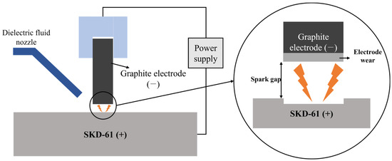
Figure 1.
Schematic illustration of EDM process using graphite electrodes.
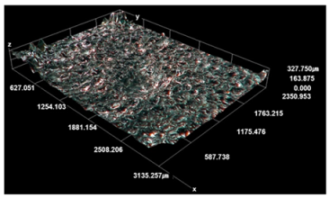
The characteristics of the graphite blocks fabricated using recycled graphite scrap were assessed and compared with those of commercial graphite block products commonly used as EDM electrodes. This comparison allowed for an objective evaluation of the performance of the developed graphite blocks as EDM electrodes. G-2800 and ELLOR20, the commercial graphite block widely used as an EDM electrode, were employed in EDM for the same duration. Subsequently, the machining depth and surface roughness of the workpiece were measured for each electrode, and the results were compared. Machining depth measurements were performed using Vernier calipers, and surface roughness was measured using a digital microscope (KH-8700, HIROX, Tokyo, Japan).
3. Results and Discussion
3.1. Bulk Density and Porosity with Respect to the Manufacturing Process
Figure 2a presents changes in the bulk density and porosity of the carbonized block and graphite blocks obtained at each stage of the manufacturing process. The bulk density of sample C was 1.30 g/cm3; its porosity was 37.3%. As the number of impregnations increased, the bulk density increased, and the porosity decreased, as exemplified by I-3, which exhibited a bulk density of 1.71 g/cm3 and a porosity of 14.0%. This pattern can be attributed to the impregnation process, during which open pores are filled with the impregnation pitch applied. As the number of impregnations increased, the rate of increase of the bulk density decreased. This is because, with repeated impregnation processes, there are fewer available pores in the graphite blocks for the impregnation pitch to occupy.
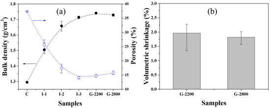
Figure 2.
(a) Bulk density and porosity and (b) volumetric shrinkage of graphite blocks.
After graphitization, both bulk density and porosity increased compared to those characteristics of the carbonized blocks. The increase in bulk density can be attributed to enhanced crystallinity and volumetric shrinkage during graphitization, as depicted in Figure 2b. According to one previous study [13], isotropic graphite blocks experience a decrease in the (002) interplanar spacing and an increase in crystallite size as the graphitization temperature rises. Consequently, the above result can be interpreted as the graphitization process resulting in volumetric shrinkage and, thus, an increase in density. The increases in porosity of both G-2200 and G-2800 are attributable to the release of hydrogen, nitrogen, sulfur, and other gases that have remained within the blocks after carbonization, occurring during the graphitization process [14].
3.2. Electrical Resistivity with Respect to the Manufacturing Process
Figure 3 presents changes in the electrical resistivity of the carbonized block and graphite blocks obtained at each stage of the manufacturing process. The electrical resistivity of Sample C was 47.9 μΩm, but as the number of impregnations increased, the electrical resistivity decreased. For example, I-3 exhibited an electrical resistivity of 27.6 μΩm. As such, electrical resistivity decreased in the order of C, I-1, I-2, and I-3 with the increasing number of impregnations, and this pattern coincides with the porosity decrease shown in Figure 2. It is well known that in most materials containing carbon components, electrical conductivity is higher when the number of pores, which inhibit electron transport, is smaller [15]. Thus, the reduced electrical resistivity observed in this study can be attributed to the decrease in porosity resulting from impregnation.
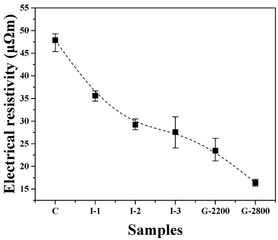
Figure 3.
Electrical resistivity of graphite blocks.
Meanwhile, the electrical resistivity of the graphite blocks was lower when the graphitization temperature was higher (refer to G-2200 and G-2800). Previous studies have reported that higher graphitization temperatures lead to increased crystallinity in graphite products. This enhancement raises the number of sp2 bonds, facilitating electron transport and resulting in reduced electrical resistivity [16,17,18]. Despite having lower porosity, G-2800 exhibited significantly lower electrical resistivity compared to G-2200. This finding suggests that the electrical resistivity of graphite blocks is more affected by their crystallinity than by their porosity.
3.3. Flexural Strength with Respect to the Manufacturing Process
Figure 4 shows changes in the flexural strength of the carbonized block and graphite blocks obtained at each stage of the manufacturing process. The flexural strength of sample C was 14.2 MPa. The flexural strength increased as the number of impregnations increased, with I-3 achieving a flexural strength of 41.0 MPa. The decrease in flexural strength was attributed to the decreased porosity resulting from impregnation treatments.
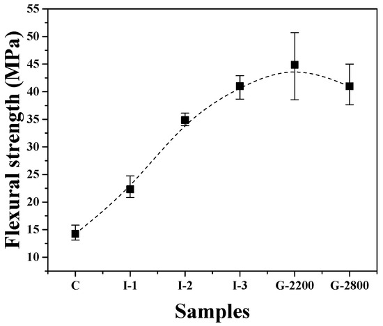
Figure 4.
Flexural strength of graphite blocks.
The flexural strength of G-2200 was slightly higher at 44.9 MPa compared to I-3, but there were significant variations in the measurements. These measurement variations among specimens can be attributed to the inconsistent formation of pores within the graphite blocks due to a phenomenon known as the puffing effect. The flexural strength of G-2800 was 41.0 MPa, which was lower than that of G-2200. This can be attributed to the increased porosity and crystallite size resulting from graphitization.
3.4. Crystallinity with Respect to the Manufacturing Process
The XRD analysis results for the blocks obtained at each stage of the manufacturing process are presented in Figure 5. For sample C, the (002) interplanar spacing was 3.378 Å, Lc was 208.6 Å, and La was 414.3 Å. The carbonized blocks developed in this study exhibited improved crystallinity compared to those made from different fillers, such as coke [13]. This enhancement can be attributed to the use of graphite scrap as filler material, as this scrap was obtained by recycling blocks intended for EDM applications that had already undergone the graphitization process.
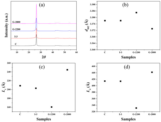
Figure 5.
XRD parameters of graphite blocks (a) XRD spectra, (b) d002, (c) Lc, and (d) La.
I-3 and G-2200 exhibited (002) interplanar spacing similar to that of Sample C, but their Lc values were slightly smaller. This occurred because the impregnation process resulted in an increase in the content of pitch, which was relatively less crystalline, within the block. G-2800, graphitized at the highest temperature employed in this study, experienced a decrease in the (002) interplanar spacing and an increase in both Lc and La compared to Sample C. In this context, the large increase in G-2800’s crystallinity was expected to significantly affect its electrical resistivity reduction.
3.5. Elemental Analysis with Respect to the Manufacturing Process
Figure 6 presents changes in the nitrogen and sulfur contents of the blocks obtained at each stage of the manufacturing process, measured through elemental analysis. The nitrogen content of sample C was 0.26 wt%, and its sulfur content was 0.25 wt%. I-3 exhibited a higher nitrogen content of 0.38 wt% but a slightly lower sulfur content of 0.23 wt% compared to sample C. As the graphitization temperature increased, both nitrogen and sulfur contents further decreased. The nitrogen content of G-2800 was 0.06 wt%, and its sulfur content was 0.02 wt%.
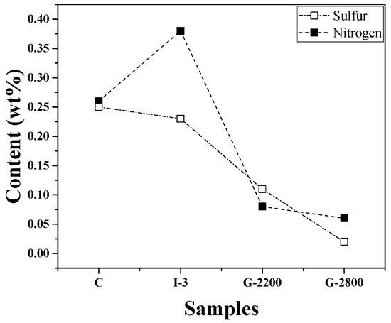
Figure 6.
Nitrogen and sulfur contents with respect to the manufacturing process.
K.I. Fujimoto et al. [19] reported that the impregnation process resulted in an increase in nitrogen and sulfur contents, leading to significant puffing. Additionally, according to Wilhelm Frohs et al. [20], primary puffing (nitrogen release) is a significant process during which gas is released from closed pores. This is followed by secondary puffing (sulfur release), in which gas release may also occur through pores that have been created during primary puffing. Accordingly, the effect of secondary puffing is considered less significant.
Compared to Sample C, sample I-3, which underwent multiple impregnation treatments, saw a significant increase in nitrogen content, while its sulfur content was even lower. Meanwhile, sulfur may be released in the form of H2S or CS2. Sulfur is also known to be released later than nitrogen-containing gas, although the exact release temperatures for each gas type have not been determined.
Based on the literature, it was initially expected that, compared to Sample C, I-3 would exhibit not only a higher nitrogen content but also an increased sulfur content. In reality, however, the nitrogen content of I-3 was higher, while its sulfur content was lower. Although further research will be required for clarity, it can be inferred that part of the sulfur-containing gas was released even within the temperature range corresponding to re-carbonization (up to 1000 °C).
3.6. EDM Performance of Graphite Blocks and Workpiece Analysis
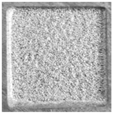
Figure 7 presents images of the graphite electrodes after EDM; these electrodes were made of developed blocks fabricated under different carbonization and impregnation conditions, as well as graphitization temperatures, and of ELLOR20, a commercial graphite block electrode for EDM. In Figure 7a–c, protrusions are visible on the electrode surface. In EDM, electrodes and workpieces can be rapidly heated to higher temperatures, e.g., 3000 °C, due to the sparks generated during the process [1]. Hence, the observed protrusions can be attributed to the sudden temperature increase, causing the puffing effect, which leads to the rapid release of the remaining nitrogen- and sulfur-containing gases within the graphite block [21].
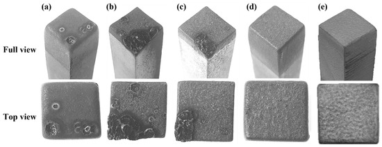
Figure 7.
Images of graphite electrodes after EDM: (a) C, (b) I-3, (c) G-2200, (d) G-2800, and (e) ELLOR20.
In I-3, in particular, the formation of protrusions on the surface after EDM was more pronounced than it was for Sample C. There are two reasons for this: first, the nitrogen and sulfur contents of the blocks increased due to the impregnation process. As previously shown in the elemental analysis results, I-3 exhibited a significantly higher nitrogen content than Sample C. Second, the impregnation process led to the formation of closed pores, along with reduced pore size. Indeed, it has previously been reported that as the number of impregnations increases, the pore size decreases while the number of closed pores increases [22]. This phenomenon may subject the pore wall to greater pressure during the release of nitrogen- and sulfur-containing gases, potentially enhancing the puffing effect [18,23].
In G-2200, while protrusions were less pronounced than they were for I-3, they were still present, as shown in Figure 7c. Puffing is known to occur within the temperature range of 1600–2500 °C [24,25]. Thus, it can be reasoned that, at 2200 °C, puffing had not yet been completed, which explains why protrusions were still visible in G-2200. Additionally, there is a possibility that the EDM process itself did not go well because the electrical resistivity was still high at 23.5 μΩm. Protrusions on the surface adhere to the workpiece or cause a fire during EDM.
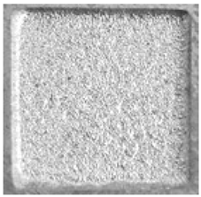
As can be seen in Figure 7d, no protrusions were observed on the surface of G-2800 after the EDM process. Next, the electrode wear rates were estimated by measuring differences in electrode length before and after EDM. G-2800 exhibited an electrode wear rate of 0.82%. It is expected that if the density of the graphite block is increased, the electrode wear rate can be decreased.
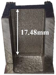
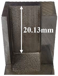
The prepared workpieces were subjected to EDM using G-2800 and ELLOR20 as graphite electrodes for six hours. The same experimental conditions were applied regardless of the electrode type. As shown in Table 2, the machining depth of the workpiece was 17.48 mm when using G-2800 as an electrode and 20.13 mm when using ELLOR20 as an electrode. The surface roughness was 0.51 μm for G-2800 and 0.44 μm for ELLOR20.
Table 2.
Morphological characteristics of workpieces after EDM using G-2800 and ELLOR20.
These elemental analyses and EDM performance results suggest that, to prevent the formation of surface protrusions after the EDM process, the weight contents of nitrogen and sulfur in graphite blocks for EDM applications should not exceed 0.1 wt%.
Table 3 summarizes the physical properties and EDM performance of the blocks obtained at each stage of the manufacturing process.
Table 3.
Physical properties and EDM performance of graphite electrodes.
The densities of G-2800 and ELLOR20 were 1.73 g/cm3 and 1.81 g/cm3, respectively. G-2800 with low density is expected to have high porosity, which leads to a decrease in mechanical and electrical properties. If further research leads to optimization of the manufacturing process, it will become possible to achieve the desired properties. In such a scenario, EDM performance comparable to that of commercial graphite products can be attained.
Compared to ELLOR20, a commercial graphite product, G-2800, which exhibited the best performance, demonstrated inferior electrode wear performance. Nevertheless, the use of recycled graphite scrap makes the developed graphite electrode a significantly favorable choice.
Coal- or petroleum-based coke is used as a filler for graphite blocks. Coal-based coke is manufactured from coke oven gas, a by-product of the steel industry, through the process of distillation, coking, and calcination. According to statistics from the International Energy Agency, carbon emissions through the steel industry are approximately 2.6 billion tons as of 2019 [27]. Replacing coal-based coke with graphite scrap can not only reduce product costs by recycling raw materials but can also contribute to CO2 reduction.
4. Conclusions
In the present study, graphite scrap from machining graphite blocks for electrical discharge machining (EDM) applications was used as a raw material for manufacturing graphite blocks; block physical properties and EDM performance were evaluated. The major findings of this study are as follows.
The graphite blocks were subjected to three impregnation treatments, followed by graphitization at 2800 °C. The resulting graphite blocks exhibited a bulk density of 1.73 g/cm3, an electrical resistivity of 16.4 μΩm, and a flexural strength of 41.0 MPa. The developed graphite blocks demonstrated physical properties that were roughly 80 to 90% of those found in commercial graphite products for EDM, confirming their suitability as recycled raw materials for EDM electrodes.
Surface protrusions formed during the EDM process in both I-3 and G-2200, indicating that the EDM process did not proceed smoothly. The observed protrusions can be attributed to the puffing effect, which leads to the rapid release of the remaining nitrogen- and sulfur-containing gases within the graphite block. This phenomenon becomes more pronounced, especially when the graphitization temperature is not sufficiently high. Consequently, in the manufacturing of graphite blocks for EDM applications, the graphitization process should be performed at sufficiently high temperatures.
G-2800 exhibited a performance inferior to that of ELLOR20 in terms of electrode wear and workpiece machining depth and surface roughness. Nevertheless, further research aiming for improved bulk density and electrical resistivity can potentially achieve the desired EDM performance. In future research, we plan to improve the physical properties by optimizing the mixing ratio of filler and binder and the particle size.
The results of this study suggest process conditions for increasing EDM performance in the manufacture of graphite blocks and can help reduce costs through the recycling of raw materials.
Author Contributions
Conceptualization, S.-H.L.; Methodology, D.-P.J.; Software, H.-Y.L.; Formal analysis, D.-P.J.; Investigation, S.-H.L.; Data curation, D.-P.J.; Writing—original draft, S.-H.L. and D.-P.J.; Writing—review and editing, D.-G.L. and J.-S.R.; Visualization, S.-H.L.; Supervision, J.-S.R.; Funding acquisition, J.-S.R. All authors have read and agreed to the published version of the manuscript.
Funding
This research was supported by a National Research Foundation of Korea grant, funded by the Korean Government (MSIP) [NRF-2018R1A6A1A03025761]. This work was supported by the Technology Innovation Program funded by the Ministry of Trade, Industry and Energy (MOTIE, Korea) [20006662]. This research was supported by the Demonstration Program funded by the Korea Carbon Industry Promotion Agency (KCarbon, Korea) [C210301001].
Data Availability Statement
Data are contained within the article.
Conflicts of Interest
Author Dong-Pyo Jeon was employed by the company GeumSungTech Co., Ltd. Author Hyun-Yong Lee was employed by the company Carbolab Co., Ltd. The remaining authors declare that the research was conducted in the absence of any commercial or financial relationships that could be construed as a potential conflict of interest.
References
- Kumar, S.; Singh, R.; Singh, T.P. Surface modification by electrical discharge machining: A review. J. Mater. Process. Technol. 2009, 209, 3675–3687. [Google Scholar] [CrossRef]
- Puertas, I.; Luis, C.J. A study on the machining parameters optimisation of electrical discharge machining. J. Mater. Process. Technol. 2003, 143–144, 521–526. [Google Scholar] [CrossRef]
- Hasçalık, A.; Caydas, U. Electrical discharge machining of titanium alloy (Ti-6Al-4V). Appl. Sufr. 2007, 253, 9007–9016. [Google Scholar] [CrossRef]
- Ming, W.; Zhang, S.; Zhang, G.; Du, J.; Ma, J.; He, W.; Cao, C.; Liu, K. Progress in modeling of electrical discharge machining process. Int. J. Heat Mass Transf. 2022, 187, 122563. [Google Scholar] [CrossRef]
- Ho, K.H.; Newman, S.T. State of the art electrical discharge machining (EDM). Int. J. Mach. Tools Manuf. 2003, 43, 1287–1300. [Google Scholar] [CrossRef]
- Kim, Y.S.; Chu, C.N. The effects of graphite powder on tool wear in micro electrical discharge machining. Procedia CIRP 2018, 68, 553–558. [Google Scholar] [CrossRef]
- Nowicki, R.; Świercz, R.; Oniszczuk-Świercz, D.; Rozenek, M. Experimental investigation of technological indicators and surface roughness of hastelloy C-22 after electrical discharge machining using POCO graphite electrodes. Materials 2022, 15, 5631. [Google Scholar] [CrossRef]
- Alam, S.T.; Amin, A.K.M.N.; Hossain, M.I.; Huq, M.; Tamim, S.H. Performance evaluation of graphite and titanium oxide powder mixed dielectric for electric discharge machining of Ti-6Al-4V. SN Appl. Sci. 2021, 3, 435. [Google Scholar] [CrossRef]
- Lee, S.H.; Lee, S.M.; Jang, W.P.; Roh, J.S. Mechanical properties of bulk graphite using artificial graphite scrap as a function of particle size. J. Korean Powder Metall. Inst. 2021, 28, 13–19. [Google Scholar] [CrossRef]
- Lee, S.M.; Kang, D.S.; Kim, W.S.; Roh, J.S. Fabrication of isotropic bulk graphite using artificial graphite scrap. Carbon Lett. 2014, 15, 142–145. [Google Scholar] [CrossRef]
- ASTM Standard C 611-98; Standard Test Method for Electrical Resistivity of Manufactured Carbon and Graphite Articles at Room Temperature. ASTM International: West Conshohocken, PA, USA, 2016.
- ASTM Standard D7972-14; Standard Test Method for Flexural Strength of Manufactured Carbon and Graphite Articles Using Three-Point Loading at Room Temperature. ASTM International: West Conshohocken, PA, USA, 2020.
- Lee, S.H.; Hwang, Y.M.; Byun, T.S.; Ko, J.H.; Roh, J.S. Effect of heating rate, temperature, and residence time during graphitization on the mechanical and electrical properties of isotropic graphite blocks. Carbon 2023, 208, 443–451. [Google Scholar] [CrossRef]
- Ōya, A.; Marsh, H. Phenomena of catalytic graphitization. J. Mater. Sci. 1982, 17, 309–322. [Google Scholar] [CrossRef]
- Sun, T.; Dong, L.; Wang, C.; Guo, W.L.; Wang, L.; Liang, T. Effect of porosity on the electrical resistivity of carbon materials. New Carbon Mater. 2013, 28, 349–354. [Google Scholar] [CrossRef]
- Im, U.S.; Kim, J.; Lee, B.R.; Peck, D.H.; Jung, D.H. Mechanical and electrical properties of MCMB/Chopped carbon fiber composite with different bead size. Sci. Rep. 2019, 9, 7065. [Google Scholar] [CrossRef] [PubMed]
- An, D.; Kim, K.H.; Lim, C.; Lee, Y.S. Effect of kneading and carbonization temperature on the structure of the carbon block for thermally conductive bulk graphites. Carbon Lett. 2021, 31, 1357–1364. [Google Scholar] [CrossRef]
- Gupta, A.; Dhakate, S.R.; Pal, P.; Dey, A.; Iyer, P.K.; Singh, D.K. Effect of graphitization temperature on structure and electrical conductivity of poly-acrylonitrile based carbon fibers. Diam. Relat. Mater. 2017, 78, 31–38. [Google Scholar] [CrossRef]
- Fujimoto, K.I.; Mochida, I.; Todo, Y.; Oyama, T.; Yamashita, R.; Marsh, H. Mechanism of puffing and the role of puffing inhibitors in the graphitization of electrodes from needle cokes. Carbon 1989, 27, 909–917. [Google Scholar] [CrossRef]
- Frohs, W.; Roeßner, F. Expansion of carbon artifacts during graphitization—An industrial issue. TANSO 2015, 267, 77–83. [Google Scholar] [CrossRef]
- Kawano, Y.; Fukuda, T.; Kawarada, T.; Mochida, I.; Korai, Y. Puffing behavior during the graphitization of coal-tar-based needle coke impregnated with iron(II) sulfate and boric acid. Carbon 2000, 38, 759–765. [Google Scholar] [CrossRef]
- Mochida, I.; Fujimoto, K.; Oyama, T. Chemistry and Physics of Carbon; Dekker: New York, NY, USA, 1994; pp. 145–148. [Google Scholar]
- Patrick, J.W.; Hanson, S. Pore Structure of Graphite, Coke and Composites; Handbook of Porous Solids; Wiley Online Library: New York, NY, USA, 2002; pp. 1900–1922. [Google Scholar]
- Hupp, T.R.; Lewis, I.C.; Criscione, J.M.; Reddy, R.L.; Fulgenzi, C.F.; Page, D.J.; Fisher, F.F.; Dzermejki, A.J.; Hedge, J.B. Graphite, Artificial. Kirk-Othmer Encyclopedia of Chemical Technology; John Wiley & Sons, Inc.: Hoboken, NJ, USA, 2000; pp. 713–771. [Google Scholar]
- Brandtzæg, S.R.; Øye, H.A. A possible mechanism of sulphur-induced graphitization. Carbon 1988, 26, 163–168. [Google Scholar] [CrossRef]
- Mersen Catalogue, Graphite Grades for Electrical Discharge Machining (EDM). Available online: https://www.mersenkorea.co.kr/sites/korea/files/publications-media/mersen_ellor_edm (accessed on 2 October 2023).
- Safarian, S. To what extent could biochar replace coal and coke in steel industries? Fuel 2023, 339, 127401. [Google Scholar] [CrossRef]
Disclaimer/Publisher’s Note: The statements, opinions and data contained in all publications are solely those of the individual author(s) and contributor(s) and not of MDPI and/or the editor(s). MDPI and/or the editor(s) disclaim responsibility for any injury to people or property resulting from any ideas, methods, instructions or products referred to in the content. |
© 2023 by the authors. Licensee MDPI, Basel, Switzerland. This article is an open access article distributed under the terms and conditions of the Creative Commons Attribution (CC BY) license (https://creativecommons.org/licenses/by/4.0/).