Abstract
In the fragile mining areas of western China, the contradiction between coal mining and water resource protection coexists prominently. Facing this issue, it is necessary to understand the dynamic relationship between mining-induced shear stress and groundwater seepage, as well as the fracture morphology of the overlying strata. In this study, the seepage characteristics of rough fractures within the rock mass are thoroughly investigated, with an emphasis on studying the effects of shear stress and seepage erosion. This research is carried out through seepage experiments and 3D fracture morphology scanning, and the research results are mainly as follows: (a) Rocks with higher shear strengths show less fluctuation in changes in fracture morphology and seepage velocity. (b) The permeability of sandstone and concrete fractures is inversely proportional to the shear stress. The layering of coal greatly limits seepage through the fractures and the permeability of coal is about one-tenth of the permeability of sandstone and concrete under the same conditions. (c) The mechanism of erosion damage to the rock by water-force coupling is the result of the shear and extrusion generated by rock fractures and the transport of rock particles. Changes in fracture erosion and seepage characteristics brought about by the damage will mutually promote and intensify the erosive effect of water force. (d) The degree of change in fracture morphology (fracture damage) under the same conditions is coal > concrete > sandstone. There are differences in the response of different types of rock to the shear stress–seepage erosion, but all show obvious changes in fracture damage and seepage characteristics.
1. Introduction
Coal mining areas in western China lie within arid and semi-arid ecologically sensitive zones. Prominent among these are the provinces and regions of Shanxi, Shaanxi, Inner Mongolia Autonomous Region, Ningxia, and Gansu. These areas account for approximately 70% of China’s total coal reserves and production, yet they hold only 3.9% of the nation’s total water resources [1]. The challenges of groundwater disturbance, pollution, and water resource restoration post-mining pose significant constraints on coal mining and the protection of surface ecology. This disparity between coal mining and water conservation is growing more acute.
In some western mining areas, due to the shallow depth of coal seams and the thinness of the overlying bedrock, large-scale, high-intensity mining activities profoundly affect the overlying rocks and the surface. Consequently, the “three belts” of overlying rocks formed by coal mining lead to the creation of water-conducting fractures in the respective layers [2]. Factors such as mining-induced fractures, mining scale, coal bed depth, and roof conditions can cause aquifer water to seep into mining areas. If not managed properly, this can result in water resource wastage, or in extreme cases, the backflow of groundwater, leading to safety hazards.
Preserving the stability of the groundwater system and ensuring the sustainability of water resources during mining operations is of the utmost importance. Currently, the simultaneous extraction of coal and water resources offers the most viable technical solution to these challenges, given the prevailing technological and economic conditions [3]. Traditional mining techniques have often led to the disruption of water barriers and a reduction in water levels. To mitigate these impacts, recent research has introduced an innovative concept that emphasises either preserving the aquifer during mining or ensuring its restoration post-mining. Central to this concept is the understanding that groundwater resources are finite and require careful management during extraction to maintain groundwater system stability. For instance, Gu et al. delved into the interplay between aquifer structure destruction and water transport in coal seam mining, proposing an underground water storage technique using the coal mine air-mining area [4,5]. Some researchers have probed the effects of coal mining on the hydraulic connectivity of overlying aquifers in specific Chinese regions, uncovering that such activities compromise the water barrier’s integrity and enhance hydraulic connectivity between overlying aquifers. In the context of augmenting water resources, contemporary mining practices aim not just to procure mineral resources but also to optimise water resource utilisation. This has birthed the concept of “extractive water resources,” which seeks to augment water resources during mining operations. Given that fractures in rock masses are primary seepage pathways, mining activities that alter shear stresses within these masses can influence fracture parameters such as opening, connectivity, and orientation [6,7] Comprehensive studies have explored how shear stress impacts seepage under various fracture parameters [8,9] and how seepage in motion can erode rocks, modifying fracture structures and properties. Current investigations have elucidated the specific mechanisms through which seepage erosion affects fractures under diverse geological conditions [10,11,12].
Under the combined effects of stress and percolation, the internal stress and strain states of rock masses undergo changes. Moreover, the interplay of physical and chemical reactions between water and rock mediums can alter the microscopic pore structures on rock and fracture surfaces, significantly influencing the rock mass’s seepage characteristics [13]. Xia et al. identified surface morphology and fracture combined morphology as pivotal factors [14]. Numerous studies have documented mechanical deterioration and microscopic changes in rocks resulting from water–rock interactions [15,16,17,18]. Brush et al. discovered that physical and chemical reactions during soaking alter fracture surface morphologies, impacting seepage pathways [19]. Several researchers have explored the properties of fracture seepage under the combined effects of stress and various solution dissolutions [20,21,22].
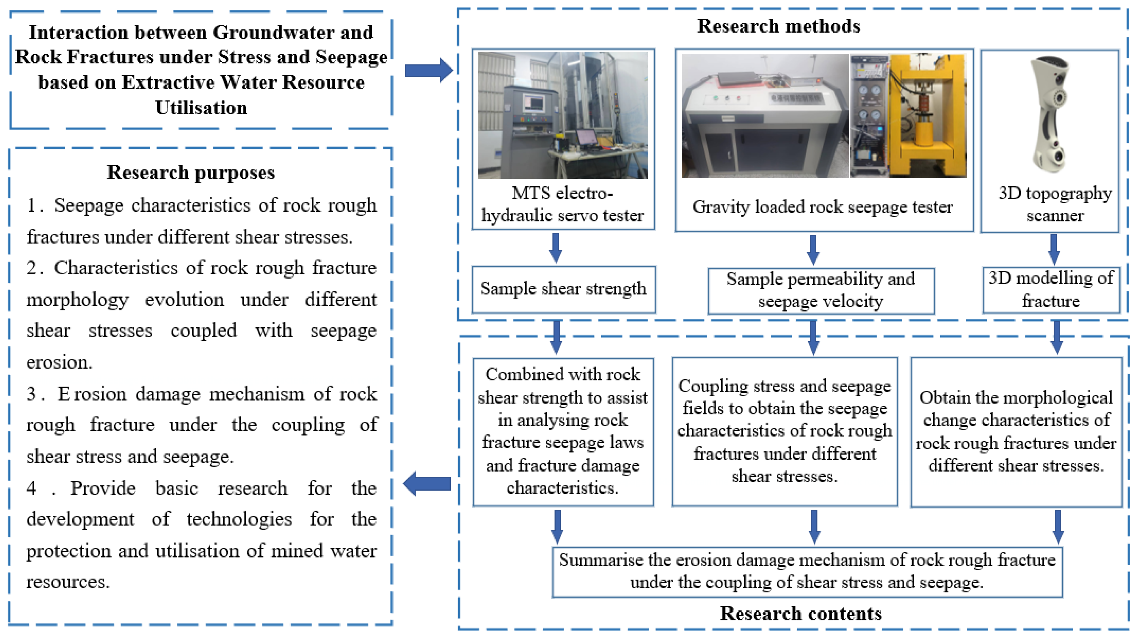
Mining-induced stress changes on fractures of coal and rock predominantly manifest as normal and shear stresses. These can significantly alter fracture openings, with shear stress directly affecting the morphology and seepage characteristics of the rough fractures. At present, some scholars have carried out research on the rock rough fracture in different fracture parameters under seepage characteristics, but a gap still exists on the quantitative study of rock fractures subjected to shear stress. Especially when seepage occurs in underground hydraulic conductive fractures, the rock fractures are in a more complex stress environment. At the same time, the stress damage of the fracture surface protrusion and the erosion of the seepage water occur inside the fracture, and the damage mechanism of the fracture and the seepage characteristics of the fracture water are not clear enough in the coupled action of the two. This paper employs the gravity-loaded rock seepage test device to conduct seepage tests on coal, sandstone, and concrete samples with rough fractures. The samples were specially treated to form fractures and fixed seepage channels consistent with natural conditions. Moreover, in order to quantitatively investigate the seepage characteristics and morphological evolution features of different rock rough fractures under different stresses under the joint action of shear stress and seepage erosion, the study makes use of three-dimensional (3D) morphology scanning technology and point cloud data processing technology. The damage characteristics of rough fracture surfaces under water-force coupling and the evolution of seepage channels were analysed using the scanned fracture morphology coordinates in terms of the pre- and post-experimental fracture profile roughness, morphology cloud maps, and a variety of morphology parameters. The technical route of the study is shown in Figure 1.
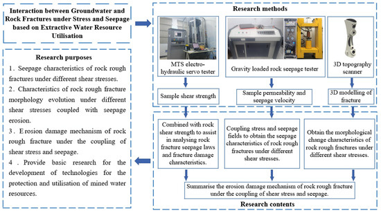
Figure 1.
Technical route of the study.
2. Sample Preparation and Test Programme Design
2.1. Experimental Equipment
This experiment can be broadly divided into three parts, which include:
- (1)
- Shear strength tests of rock samples. Before conducting any seepage experiments, it is crucial to determine the shear strength of the various rock samples. It can also help us to study the damage to rough fracture surfaces of rocks of different strengths under water-force coupling. The insights derived from these tests will provide foundational knowledge for understanding the evolution of seepage channels.
- (2)
- Rough fracture seepage experiments. In the experiment, we will couple the stress field with the seepage field to investigate the seepage characteristics of the rock fractures and the fracture damage law.
- (3)
- 3D topographic scanning. This scan is performed on the fracture surface of each sample, both pre- and post-seepage experiment.
For the shear strength experiments on varied material samples, servo loading was employed using an MTS universal testing machine.
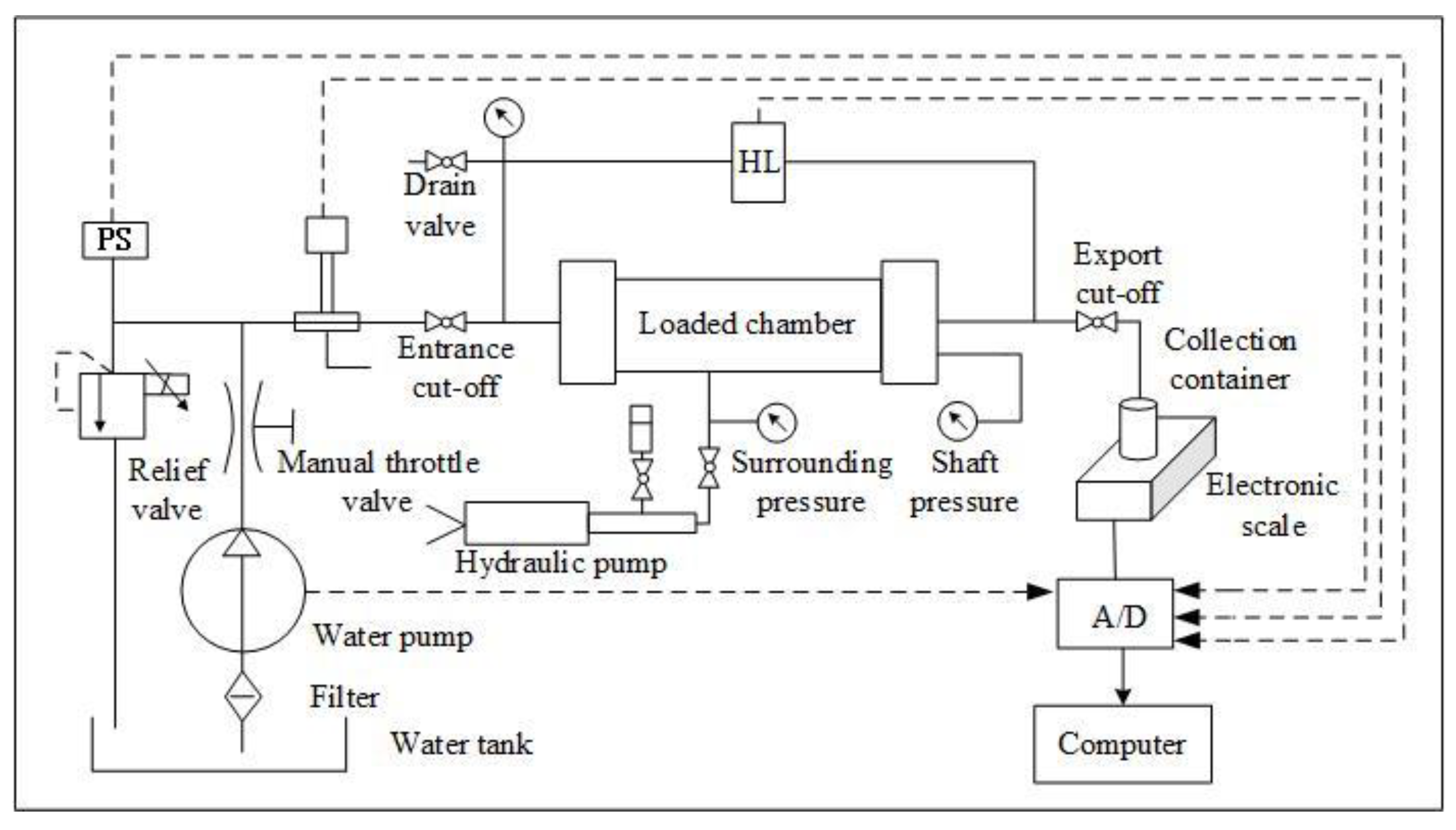
In the seepage experiment, the gravity-loaded rock seepage test platform from China University of Mining and Technology (the explanations of Chinese characters in Figure 2) was used, which consists of six systems, namely, a load-bearing system, loading system, temperature-control system, seepage system, measurement system, and automatic acquisition and control system. Where the axial load σ1,max in the loading system is 300 kN, radial load σ2,max = σ3,max = 25 Mpa. The pressure upstream pw,max of the liquid seepage in the seepage system is 20 MPa. The equipment can be used to carry out triaxial coal and rock mechanics experiments and seepage experiments under different stress paths and to collect data through high-precision sensors and other equipment. The seepage experiment equipment is shown in Figure 2, and the schematic diagram of the equipment is shown in Figure 3.
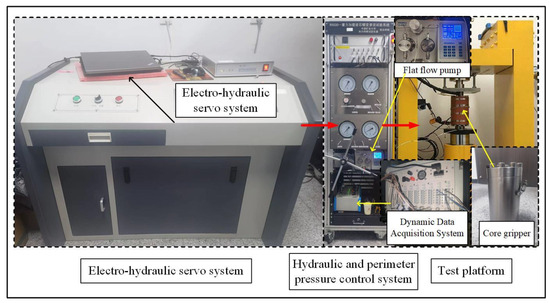
Figure 2.
Rock seepage test platform with gravity loading.
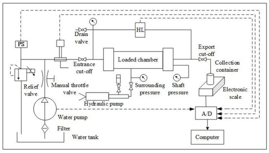
Figure 3.
Schematic diagram of the seepage device.
The experiment utilised a portable high-precision 3D scanner to capture the three-dimensional (3D) morphology of the rough fracture surfaces. The scanner boasted a formidable scanning rate of 2,000,000 points/s, with a measurement accuracy of 0.1 mm and a resolution of 0.25 mm. Figure 4 depicts both the equipment in use and the resultant scanning effect.
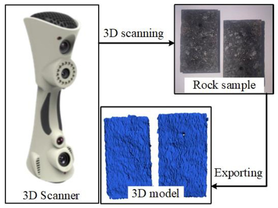
Figure 4.
3D morphology scan.
2.2. Sample Preparation
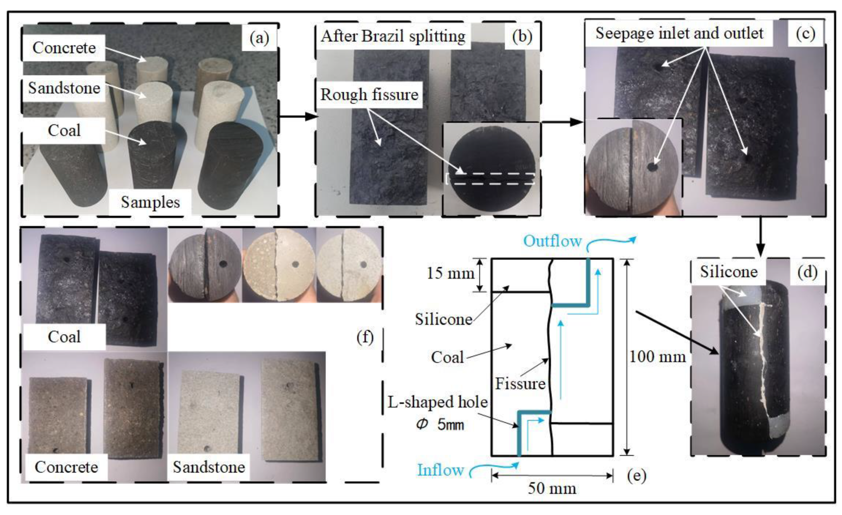
The goal of this phase is to investigate the seepage characteristics and evolution of seepage channels for different rock types under varying shear stress conditions. This necessitated the selection of diverse materials. For this study, three commonly encountered engineering rock masses were chosen: coal, sandstone, and concrete. In this regard, the following concrete composition ratios were chosen in order to ensure that the concrete samples had a good castability and formability while having a certain strength. The concrete mix was prepared using a ratio of cement, sand, and water of 1:3.5:0.65, respectively.
Standard cylindrical samples had 𝜙 ≤ 50 mm and H ≤ 100 mm, as recommended by the International Society for Rock Mechanics (ISRM) [23]. Therefore, in this experiment, the selected samples were machined into cylindrical samples with dimensions 𝜙 = 50 mm and H = 100 mm, and the cylindrical samples were polished and sanded to achieve a more desirable flatness and roughness on the surface of the samples. The Brazilian splitting method was used to split axially along the cylinder when prefabricating a rough fracture.
To facilitate tangential displacement in the sample, 15 mm was removed from the top and bottom of the split sample. Subsequently, 5 mm diameter holes were drilled at both ends to serve as the inlet and outlet for seepage flow. It was imperative to ensure these holes connected to the internal rough fracture surface, providing a conduit for seepage flow. Silicone was utilised to seal both the truncated sections at the sample’s ends and the fractures on the sample cylinder’s side. Given silicone’s deformability and impermeability, it ensured that the rock’s seepage pathways were limited to the rough fractures, even when the sample experienced shear and displacement. The sample preparation process is depicted in Figure 5. The creation of the rough fracture represents a critical step in the experiment. By using the split rock mass fractures, researchers can emulate the natural fractures present in the rock mass. Simultaneously, the specifically designed seepage holes guarantee unobstructed seepage through the rock mass fractures. This ensures that they maintain a connected state throughout the test, enabling a thorough exploration of the seepage characteristics of the rough fractures.

Figure 5.
Sample preparation. (a) Standard samples; (b) split open; (c) seepage hole; (d) complete samples; (e) seepage pathway; (f) different samples.
2.3. Experimental Programme
Most rock masses experiencing seepage under natural conditions are in a water-saturated state. Consequently, before commencing the experiments, it is essential to ensure the coal, sandstone, and concrete samples are thoroughly saturated with water. For this saturation process, we employed a non-destructive water immersion device developed at the China University of Mining and Technology. This ensures the sample remains intact post-saturation. Throughout the immersion process, the samples were periodically weighed, allowing for the calculation of water content. This continued until the samples achieved a fully saturated state.
For the determination of uniaxial shear strength across different sample types, cylindrical samples measuring 50 mm × 50 mm were employed. The variable angle shear experimental method was utilised, with chosen shear angles of 55°, 60°, and 65°. A loading rate of 0.4 mm/min was set, continuing until the samples reached their point of failure. The compressive and shear strengths for coal, sandstone, and concrete were then calculated, with their respective average values being derived. The varied strength attributes of coal, sandstone, and concrete to some extent reveal the damage patterns of rock rough fractures under different stress scenarios. Such insights are crucial for the subsequent analysis of the seepage behaviors of rock rough fractures when subjected to the coupling of shear stress and seepage.
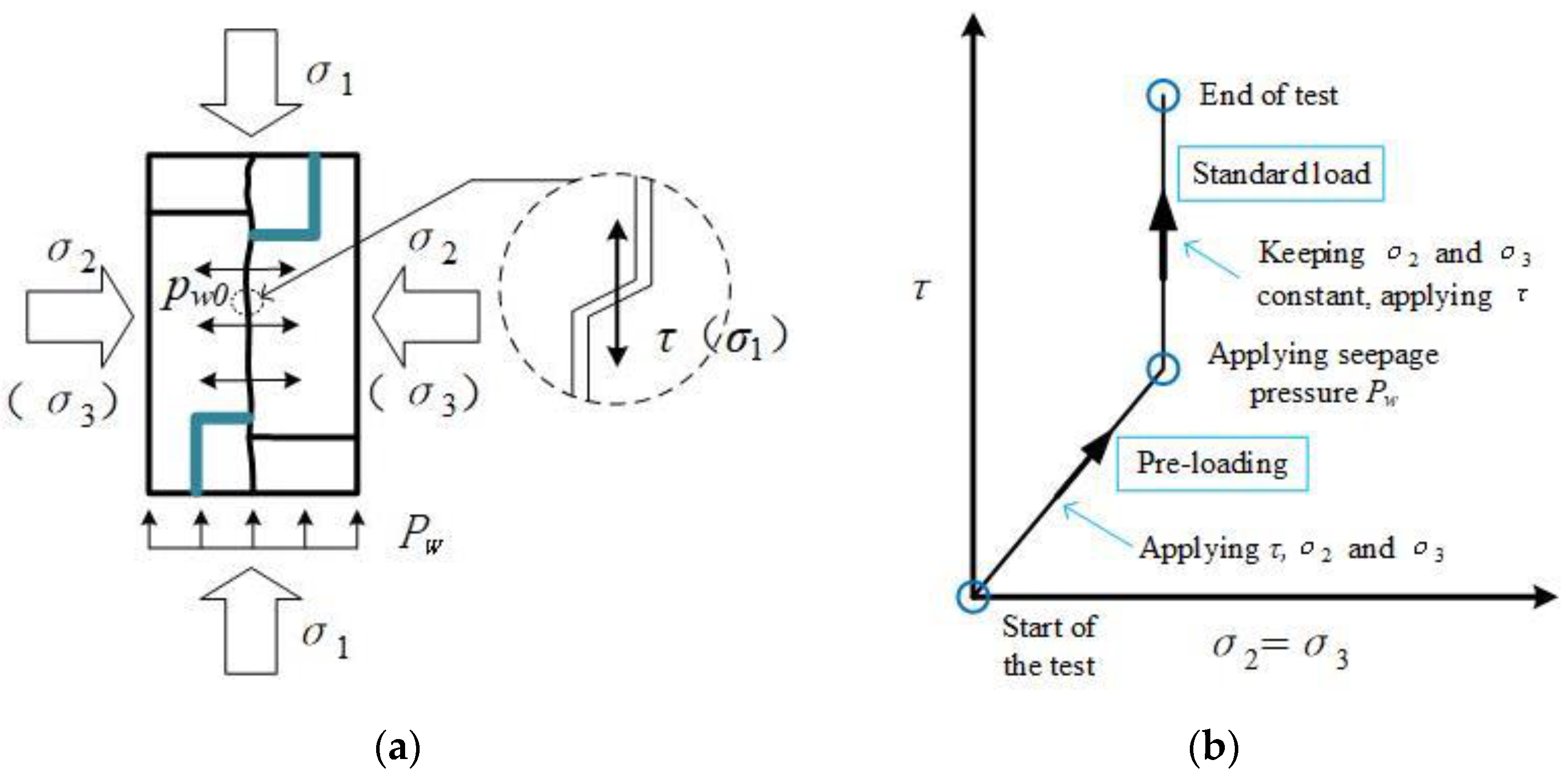
In the laboratory seepage experiments, three main independent variables were set, namely, different rock materials, roughness of the fracture, and shear stress of the rough fracture, and the dependent variable was permeability. In this experiment, the rough fracture formed with Brazilian splitting simulates a fracture in a natural rock mass. The samples on both sides of the fracture are subjected to axial stress to produce tangential displacement, and inside the rough fracture there are surface morphologies with different degrees of roughness due to splitting, while the rough fracture surfaces belong to the state of mutual occlusion in the experiment. In the case of a certain peripheral pressure, the axial stress σ1 of the sample can be regarded as the shear stress τ of the rough fracture, and it is assumed that the axial stress of the sample and the shear stress of the rough fracture are approximately equal in this experiment. The sample will be subjected to the stresses of axial pressure σ1, circumferential pressure σ2, σ3 (σ2 = σ3), and seepage pressure pw, and at the same time, it will also be subjected to the penetration pressure pw0 in the rough fracture; these stresses are shown in Figure 6a [24].
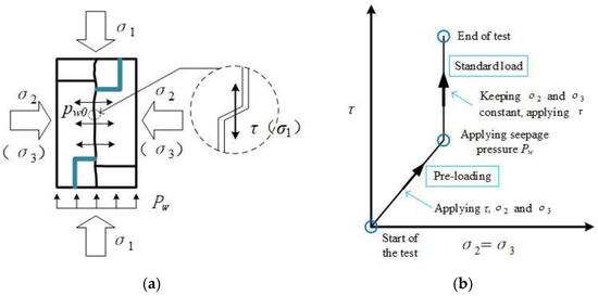
Figure 6.
(a) Schematic representation of forces; (b) stress paths.
According to the parameters and specifications of the experimental equipment, the initial stress conditions for the rough fracture seepage experiment were 4.0 MPa for the perimeter pressure to remain constant and 0.4 MPa, 0.5 MPa, and 0.6 MPa for the permeability pressure to remain constant. The initial value of shear stress in the rough fracture was set to 5.0 MPa, and the subsequent test was carried out using a step-by-step loading method. The shear stress was increased by 2 MPa at each stage, and a total of six sets of shear stresses was set for the experiment, which were 5 MPa, 7 MPa, 9 MPa, 11 MPa, 13 MPa, and 15 MPa. The stress loading path is shown in Figure 6b. The stress loading scheme is shown in Table 1.

Table 1.
Stress loading programme.
On the gravity-loaded rock seepage test platform, stress-controlled loading was used, and the axial and peripheral pressures were gradually loaded until the peripheral pressure reached 4.0 MPa and the axial pressure reached 5.0 MPa. After the peripheral pressure and the axial pressure were stabilised, the seepage pressure was loaded using an advective pump at a constant flow rate of 0.4 MPa, and the data were recorded after the seepage had reached a stable level. The above operation was repeated until the seepage test under different shear stresses in the rough fracture was completed.
3. Seepage Characteristics of the Rough Fractures under Different Shear Stresses
Under the influence of tangential stress, rock rough fractures experience shear slip. This shear movement inflicts damage on the protruding structures between the fracture surfaces. Such damage leads to alterations in the rough fracture openings, subsequently influencing their seepage properties.
3.1. Shear Strength Characteristics of Different Rock Masses
C.A. Coulomb proposed Coulomb’s criterion and argued that the damage of rocks is mainly shear damage, which is related not only to the shear stress on the shear plane, but also to the positive stress acting vertically on the shear plane [25,26,27]. Rock shear strength can be expressed as Equation (1).
where τ is the shear stress or shear strength on the shear surface (MPa); σ is the positive stress on the shear surface (MPa); φ is the angle of internal friction of the rock (°); and c is the cohesion of the rock (MPa).
In the shear test of rock, the positive stress σ and the shear stress τ on the sample can be calculated from Equations (2) and (3).
where τ is the shear stress or shear strength on the shear surface (MPa); σ is the positive stress on the shear surface (MPa); P is the axial load when the sample is destroyed (N); A is the shear area (mm2); f is the friction coefficient of the shear press mould. When the experimental equipment is well lubricated, f is negligible.
By changing the shear angle of the experimental fixture to load different rock samples, combining Equations (2) and (3), the mechanical parameters corresponding to different shear angles of coal (C), sandstone (S), and concrete (Ct) samples are shown in Table 2.
Table 2.
Mechanical parameters of different shear experiments for each sample.
The cohesion and angle of internal friction of a rock sample are crucial determinants of the rock mass’s shear strength. Based on Equation (1), the relationship between shear stress and positive stress for each sample type (coal, sandstone, and concrete) can be derived, as illustrated in Figure 7. By fitting curves for coal, sandstone, and concrete and contrasting these with the Moore–Cullen criterion, both the cohesion and angle of internal friction can be discerned. These values are tabulated in Table 3.
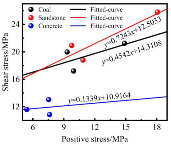
Figure 7.
Shear stress–positive stress distribution of different samples.
Table 3.
Parameters of internal friction angle and cohesion for different samples.
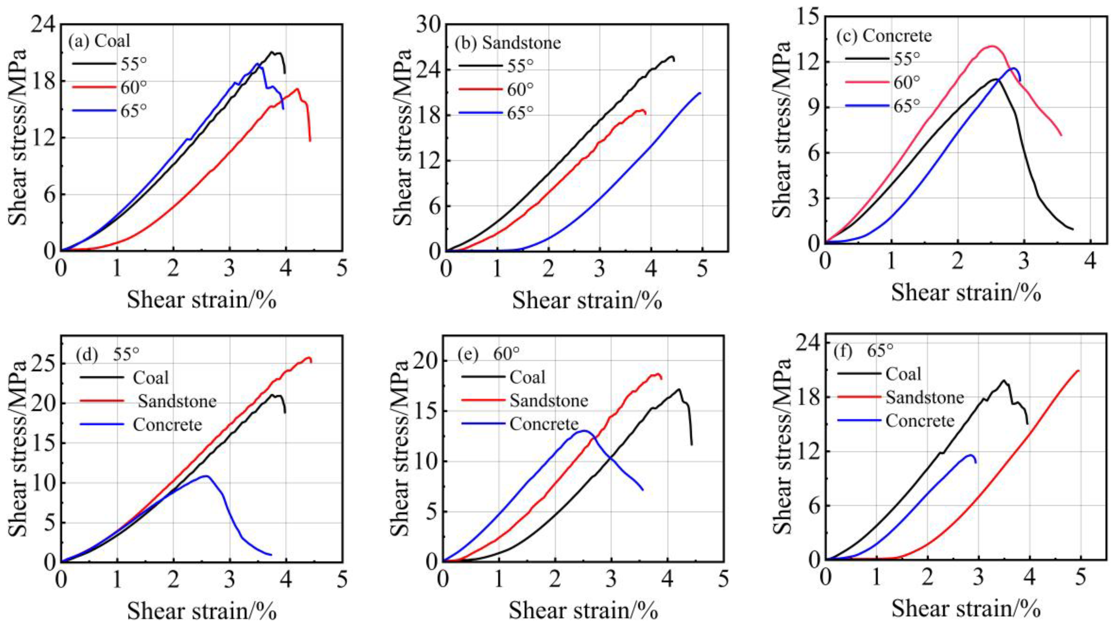
Examining the cohesion values for coal, sandstone, and concrete reveals that these materials possess similar mutual attraction abilities among adjacent components within the rock mass. However, there is a substantial disparity in the internal friction angle among these three rock types. The internal friction angle signifies the internal frictional strength within the rock mass, representing the sliding friction and mechanical interlocking friction between the rock particles. When calculating the average shear strength of these three rock types under shear angles of 55°, 60°, and 65°, it becomes evident that the shear strength ranking is as follows: sandstone > coal > concrete. This hierarchy is indicative of the differing mechanical behaviors of these materials. Figure 8 illustrates the shear stress–shear strain relationships for various rock types at different shear angles.
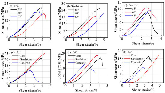
Figure 8.
Shear stress–shear strain relationships for different rock masses at different shear angles. (a–c) Shear stress–shear strain relationships for coal, sandstone, and concrete at different shear angles, respectively; (d–f) Shear stress–shear strain relationships for different rock masses at 55°, 60°, and 65° shear angles, respectively.
Comparing the shear stress–shear strain curves for the same rock type at various shear angles reveals a gradual decrease in shear strength as the shear angle increases. Concrete samples, due to their homogenous nature, exhibit relatively minor changes in shear strength when subjected to similar shear angles. The influence of shear angle is more pronounced in rock masses with higher shear strength. For instance, consider sandstone, which possesses a high shear strength: a 10° change in shear angle corresponds to an approximately 24% alteration in shear strength. In a similar scenario, coal samples experience a roughly 15% change in shear strength, while concrete samples, with a lower shear strength, display a nearly 14% change in shear strength when the shear angle shifts by 10°. When comparing the shear stress–shear strain curves of different rock types under the same shear angle, it becomes evident that the shear strength of rock masses is significantly influenced by factors such as stratification and structural compactness. Sandstone, characterised by smaller particles, improved homogeneity, and compact structure, exhibits resilience against shear damage when subjected to shear forces.
3.2. Seepage Characteristics of Rough Fractures under Different Water Pressures
When investigating the seepage characteristics of rough fractures, it is essential to account for variation under different seepage water pressure conditions. The morphology of rough fractures within a rock mass profoundly influences groundwater flow and storage. As the seepage pressure undergoes changes, both the rate and direction of seepage within the fracture can be altered. Under low seepage pressures, the water flow velocity within the fracture tends to be sluggish, resulting in a relatively steady flow along the primary fracture direction. However, with increasing seepage water pressure, the flow velocity may gradually escalate, potentially reaching levels that induce shear stresses. This can lead to more intricate water flow patterns within the fracture, potentially giving rise to nonlinear phenomena like eddies and countercurrents. Furthermore, the coupling of shear stress and seepage erosion may impact the degree of fracture opening and closing. Under low seepage water pressure conditions, the fracture tends to remain relatively stable, exhibiting small opening and closing amplitudes. However, as the seepage water pressure rises, the force of water may lead to increased fracture opening, possibly resulting in fracture expansion and deformation. Such changes can significantly affect the morphology of the seepage channel.
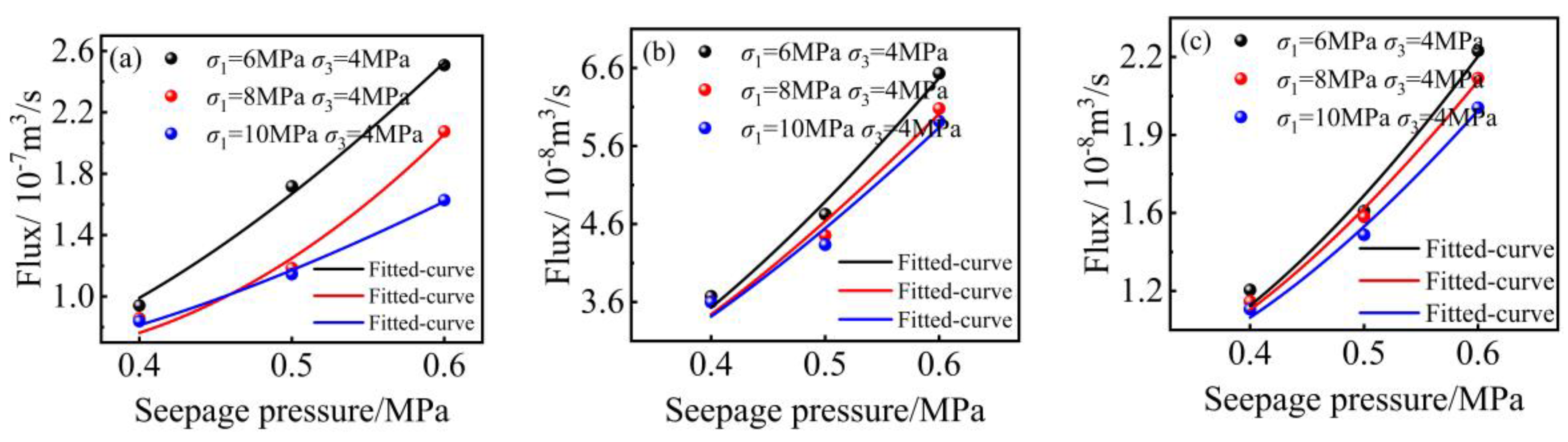
A series of coal, sandstone, and concrete samples was tested under different seepage pressures and shear stresses to establish the relationship between seepage velocity and seepage pressure, as depicted in Figure 9.
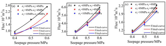
Figure 9.
Relationship between seepage velocity and seepage pressure for different samples. (a) Concrete; (b) sandstone; (c) coal.
According to the cubic law and Darcy’s law it is known that the permeability of the rock mass can be expressed by Equations (4) and (5) [28].
where k is the permeability of the sample (m2); Q is the total flow rate through cross-section A of the sample (m3/s); is the dynamic viscosity of the water (N∙s/m2); is the pressure difference between the upstream and downstream of the seepage flow (Pa); and l is the seepage path (m).
And as shown in Figure 9, when seepage occurs when the fluid enters the pores and rough fractures within the rock mass, it can be found that the seepage pressure and flow rate show a nonlinear increase because the fluid is in a nonlinear flow region. The Forchheimer equation can better describe the seepage behaviour in the pore and fracture medium of the rock mass, as shown in Equations (6) and (7).
where ρ is the fluid density (kg/m3); β is the inertia resistance coefficient.
The relationship between permeability and seepage pressure across different samples reveals that, under identical stress conditions, the seepage rate follows the order concrete > sandstone > coal. Concrete, characterised by a lower strength and smaller internal pores, exhibits a faster seepage rate when subjected to concurrent external stress and seepage flow. This is due to the increased erosion and damage inflicted upon concrete cracks under these conditions. Conversely, coal, with its distinct laminar structure, imposes certain hindrances on fluid seepage within its pores and fractures, resulting in a slower seepage rate.
Maintaining a constant surrounding pressure while elevating the tangential stress on rock masses containing rough fractures leads to a notable reduction in the rough fracture seepage velocity. The reduction in seepage velocity is less pronounced for rock masses with a higher shear strength but more significant for those with a lower shear strength. For example, consider the concrete sample with a lower shear strength: at a seepage pressure of 0.6 MPa, increasing the tangential stress from 6 MPa to 10 MPa results in a roughly 47% decrease in the rough fracture seepage velocity. In a similar scenario, sandstone, characterised by a higher shear strength, experiences only about a 16% reduction in seepage velocity. This phenomenon may be attributed to the coupling of shear stress and seepage, which damages and reconfigures the morphology of the rough fracture surface, altering the seepage channel and subsequently reducing the seepage velocity. Rock masses with lower shear strength are more susceptible to damage on the rough fracture surface, leading to a more pronounced reduction in seepage rate.
3.3. Study of the Coupled Effect of Shear Stress and Displacement on Seepage Characteristics of Rough Fractures
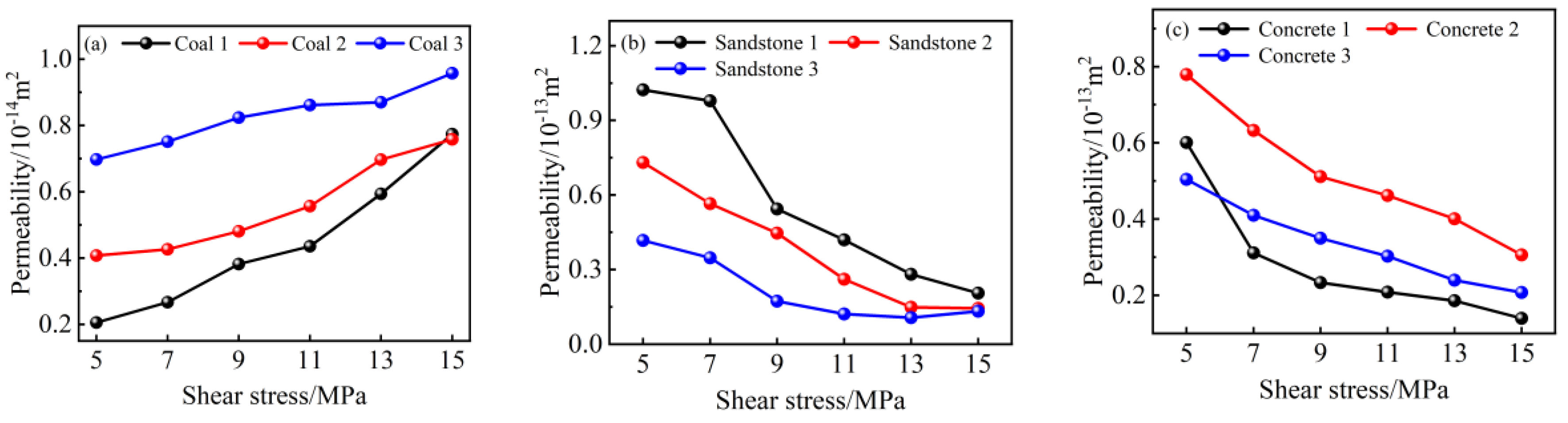
A consistent seepage pressure of 0.5 MPa was maintained, while the peripheral pressure remained constant at 4 MPa. Multilevel tangential stresses were introduced to conduct seepage experiments, and the results of these experiments are presented in Figure 10.
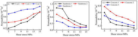
Figure 10.
Rough fracture permeability under different shear stresses. (a) Coal; (b) sandstone; (c) concrete.
Through the analysis, it is evident that the permeability of rough fractures in sandstone and concrete samples exhibits a negative correlation with shear stress. As the shear stress increases on these rough fractures, the permeability gradually decreases. In contrast, the permeability of coal samples shows a positive correlation with shear stress, with permeability increasing as shear stress on the rough fractures rises. When incrementally increasing the tangential stress, the permeability changes in coal samples by an average of 131.25%, with specific changes of 270.47%, 85.99%, and 37.30%. For sandstone samples, the permeability changes by an average of 76.18%, with specific changes of 79.94%, 80.27%, and 68.34%. Concrete samples experience an average permeability change of 65.54%, with specific changes of 76.83%, 60.85%, and 58.93%. Under the same stress conditions, the change in permeability is most pronounced in coal samples. This phenomenon may be attributed to the better homogeneity and smaller particle size of rock particles in the sandstone and concrete samples. Under the influence of shear stress, the rough fractures undergo shear slip, causing shear damage to the convex bodies on the rough fracture surface. Additionally, fine rock particles, driven by seepage pressure, reduce the roughness of the fracture surface, leading to decreased fracture openings and permeability. In the case of coal, its special stratification and non-homogeneity result in rough fractures undergoing shear slip along the direction of stratification, leading to increased fracture openness and permeability. By comparing the permeability of the three types of samples, it can be seen that the permeability of the coal is about one-tenth of the permeability of the other two types of samples. This emphasises the notable influence of rock mass stratification on the seepage characteristics of rough fractures.
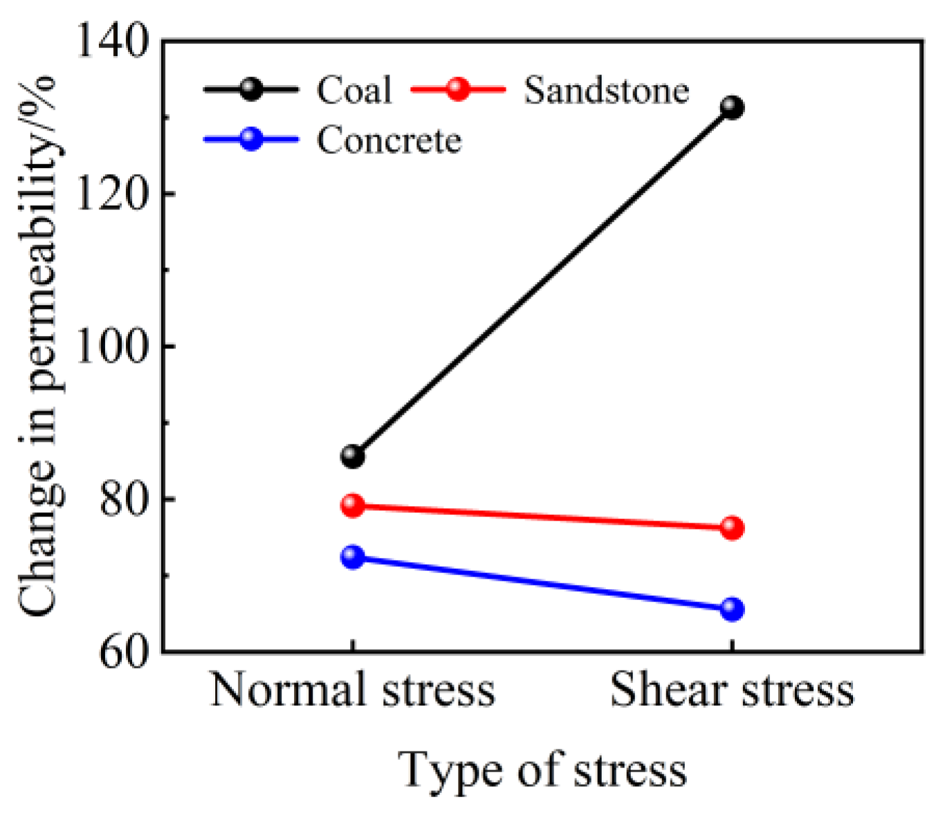
Furthermore, control experiments were conducted to study the influence of stress on the seepage characteristics of rough fractures. These experiments employed peripheral pressures (normal stresses) of 5 MPa, 7 MPa, 9 MPa, 11 MPa, 13 MPa, and 15 MPa, along with a shear stress of 4 MPa, while maintaining a constant seepage pressure of 0.5 MPa. The average changes in permeability for coal, sandstone, and concrete rough fractures under various stress conditions are illustrated in Figure 11.
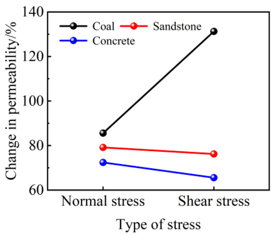
Figure 11.
Variation in sample permeability under different kinds of stresses.
Comparing the two forms of stress, it becomes evident that both normal stress and shear stress have significant impacts on the seepage characteristics of rough fractures. In the case of coal, which exhibits pronounced stratification, the influence of shear stress on rough fracture permeability is approximately twice as significant as that of normal stress. This underscores the importance of studying the coupling of shear stress and seepage erosion to understand its impact on the seepage characteristics of rough fractures in different rock masses. The investigation of rough fracture seepage characteristics under varying shear displacements plays a pivotal role in the study of shear stress–seepage erosion coupling. By comparing the seepage characteristics under different shear displacements, a deeper understanding of how shear displacement affects fracture permeability, flow velocity distribution, and changes in seepage channels can be attained. This exploration aids in unveiling the relationship between rock deformation and seepage. Figure 12 illustrates the permeability of rough fractures in coal, sandstone, and concrete samples under different shear displacements.
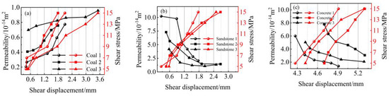
Figure 12.
Variation in rough fracture permeability of samples under different shear displacements. (a) Coal; (b) sandstone; (c) concrete.
The figure above illustrates the permeability changes in rough fractures during the shearing process. While there are some variations in permeability changes among different shear displacements, they generally follow a consistent pattern: under constant peripheral pressure, an increase in shear displacement leads to a gradual decrease in the rate of permeability change, eventually stabilising. This phenomenon primarily results from the closure of contacts between the asperities on the rough fracture surfaces, altering the seepage paths between the fractures and, consequently, affecting permeability. The behavior of coal sample rough fractures is influenced by stratification, leading to increased permeability with higher shear displacement. In contrast, sandstone and concrete sample rough fractures exhibit decreased permeability as shear displacement increases. When comparing the shear displacement of rough fractures in coal, sandstone, and concrete samples under shear stress–permeability coupling, it becomes evident that the shear displacement inversely correlates with the shear strength of the rock mass’s structural surface. With increasing shear displacement, the permeability of rock types with smaller particles, such as sandstone and concrete, further decreases. This is primarily due to the bulges between fractures reaching the peak strength of shear rupture during shear stress, causing changes in fracture openness. Simultaneously, some rock particles are transported to the fracture cavity region by the seepage water, leading to both seepage channel blockage and decreased rough fracture permeability. As the shear displacement continues to increase, the permeability gradually stabilises. This stabilisation occurs because high-angle bumps between the fracture surfaces experience complete shear rupture and wear during the later stages of shear, and the shear slip between the fractures becomes similar to the sliding of flat plates. Consequently, changes in shear stress (shear displacement) no longer significantly affect the fracture seepage rates.
4. Analysis of the Change Rule of Rough Fracture Morphology Characteristics under Hydraulic Coupling Effect
The sliding of fracture surfaces under the influence of tangential stress leads to a relative misalignment of the upper and lower surfaces. This misalignment causes the original occlusal rough bumps within the fracture surface to squeeze and shear against each other, resulting in the destruction of the fracture surface. Once the fracture surface is damaged, the 3D morphology of the surface changes, leading to alterations in the seepage characteristics of the fracture due to modifications in the seepage channels within the fracture surface.
This section emphasises the coupling relationship between shear stress and seepage erosion while analysing their effects on rough fracture morphology and seepage characteristics within the framework of hydraulic coupling. By investigating the mechanism of seepage erosion and conducting corresponding experimental measurements involving 3D scanning of fracture morphology, the influence of erosion on the evolution of fracture geometry and seepage channels is revealed. This analysis explains how this coupling relationship further impacts fracture permeability, flow velocity, and seepage channels.
4.1. Erosion Damage Mechanism of Rough Fractures under Hydraulic Coupling Action
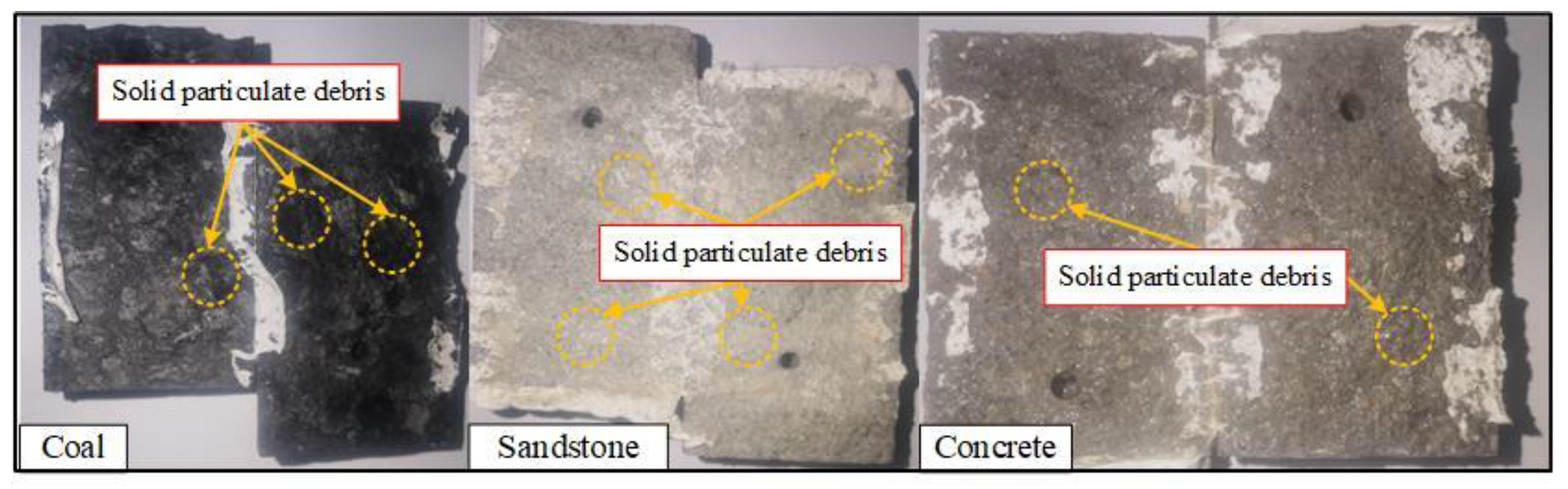
In the seepage experiments conducted on coal, sandstone, and concrete samples, a noticeable phenomenon was observed: the accumulation of rock particles on the fracture surfaces of these samples after the seepage experiments, as depicted in Figure 13. Additionally, a substantial quantity of rock particles was observed in the water flowing out of the downstream outlet of the test apparatus during the experiments. The occurrence of extrusion and shear damage in different regions of the fracture surfaces under tangential stresses, as a result of stress–seepage coupling, led to local damage within the fractures. This damage caused the rough bumps of rock particles on the fracture surfaces to be peeled off, resulting in the formation of large accumulations of particles. Moreover, the shear misalignment of rock particles within the fractures led to a reduction in the local fracture roughness.
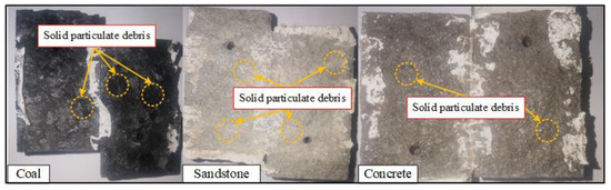
Figure 13.
Inside the fracture surface after seepage experiments.
From these observations, it can be concluded that fractures generate rock particles under the combined influence of shear stress and seepage, resulting in the phenomenon of particle transport and accumulation. These transported particles are then deposited within the raised areas of the opposing fracture surface, aided by the flow of water. As a consequence, the fracture experiences more pronounced shear damage under the influence of tangential stress, exacerbating the overall fracture damage and leading to changes in fracture surface morphology characteristics.
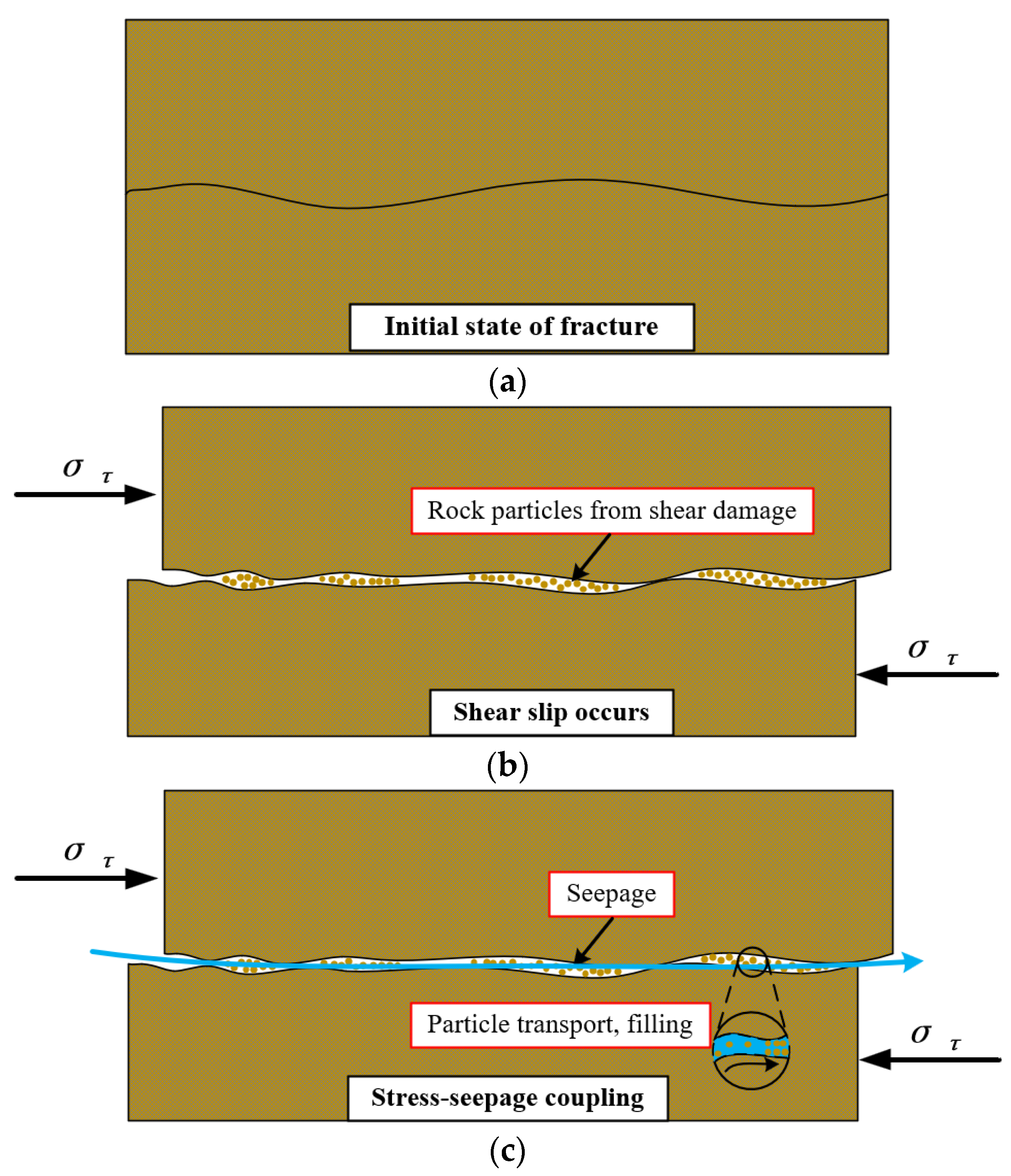
The reason for this phenomenon is that the protruding parts on the slit surface extrude each other and shear damage occurs, resulting in the protruding parts being sheared off. In-depth investigation of the mechanism of its action on samples between the fracture surface of the raised contact show shear sliding and shear breakage; the resulting raised broken material will have shear rolling, micro-rupture, abrasion, and spatial redistribution, which in turn affect the seepage of the fracture, the strength of the characteristics of the fracture including the fracture permeability, the fracture surface shear strength and hydraulic conductivity, etc. [29]. Under the coupling effect of shear stress and seepage pressure, the mechanical strength of the rock particles in the fracture surface will be reduced, resulting in a softening phenomenon, which makes it easy to produce damage and injury in the seepage process. At the same time, due to the destruction and shedding of particles in the seepage pressure driven by the transport of the fracture surface, changing the fracture morphology characteristics also changes the fracture of the original seepage channel. When this part of the rock particles is transported to the narrow area of the fracture, it will produce a filling effect on the fracture, and when it is extruded from the fracture contact surface, shear will exacerbate the fracture surface via the hydrodynamic coupling of erosion damage, the principle of which is shown in Figure 14.
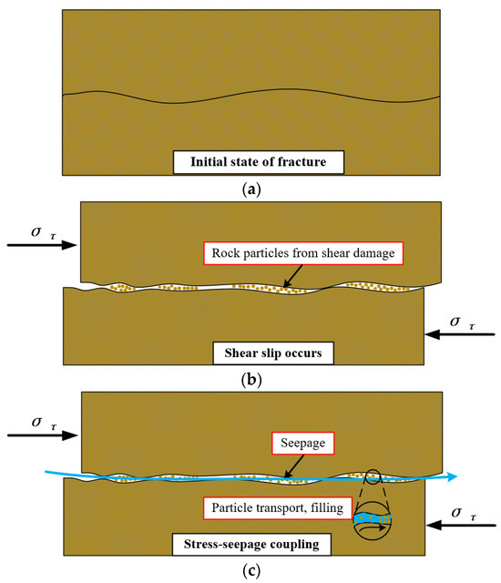
Figure 14.
Fracture damage mechanism under shear stress–seepage erosion coupling. (a) Initial state of fracture; (b) shear slip occurs; (c) stress–seepage coupling.
4.2. Changing Law of Rough Fracture Morphology under Hydraulic Coupling Effect
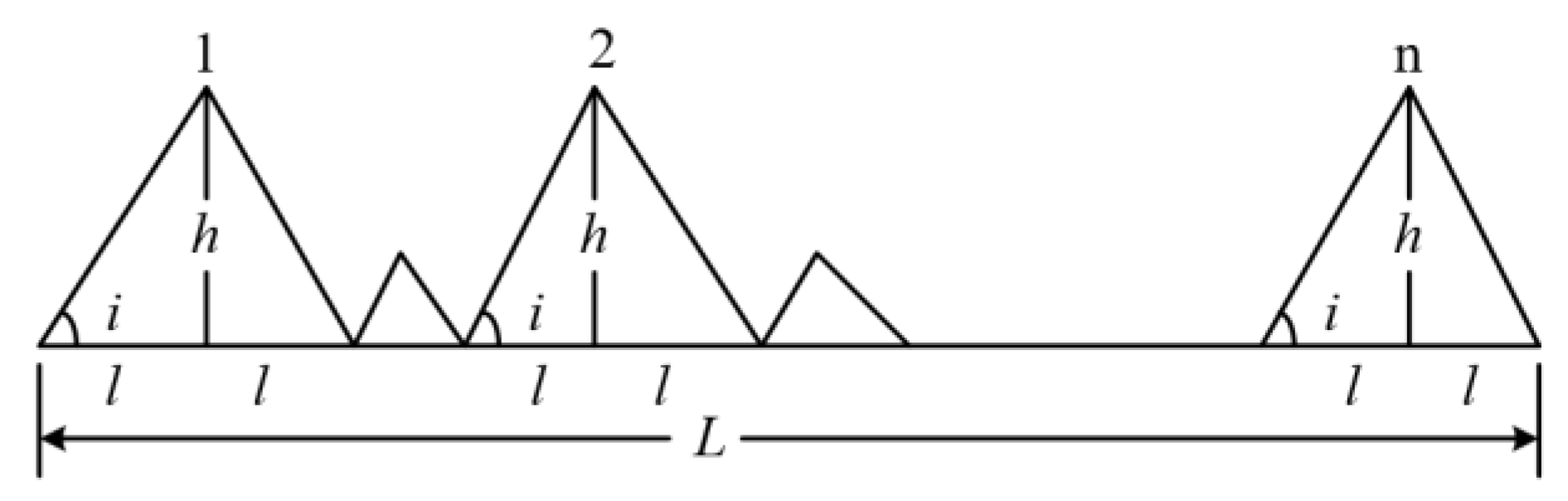
In the rough fracture geometric features, the fracture roughness is determined by the fracture’s own geometric properties, while the rest of the factors are formed by the fracture morphology features under the external stress. Thus, the fracture roughness can be regarded as a basic unit that constitutes the geometric characteristics of the fracture, so it is very important to quantitatively investigate the change rule of the fracture roughness. The JRC modified straight edge method can be used to quantitatively characterise the rock fracture roughness [30] as shown in Figure 15.
Figure 15.
Geometric model of fracture structure surface.
The surface undulation of the fracture surface can be simplified to a jagged structure with geometrically
where L is the sampling length of the structural surface, cm; A is the height of the larger serrations or the undulation of the structural surface; and n is the number of larger serrations.
, , where RA is the relative amplitude of the structural plane.
Corrected for size effects, this gives
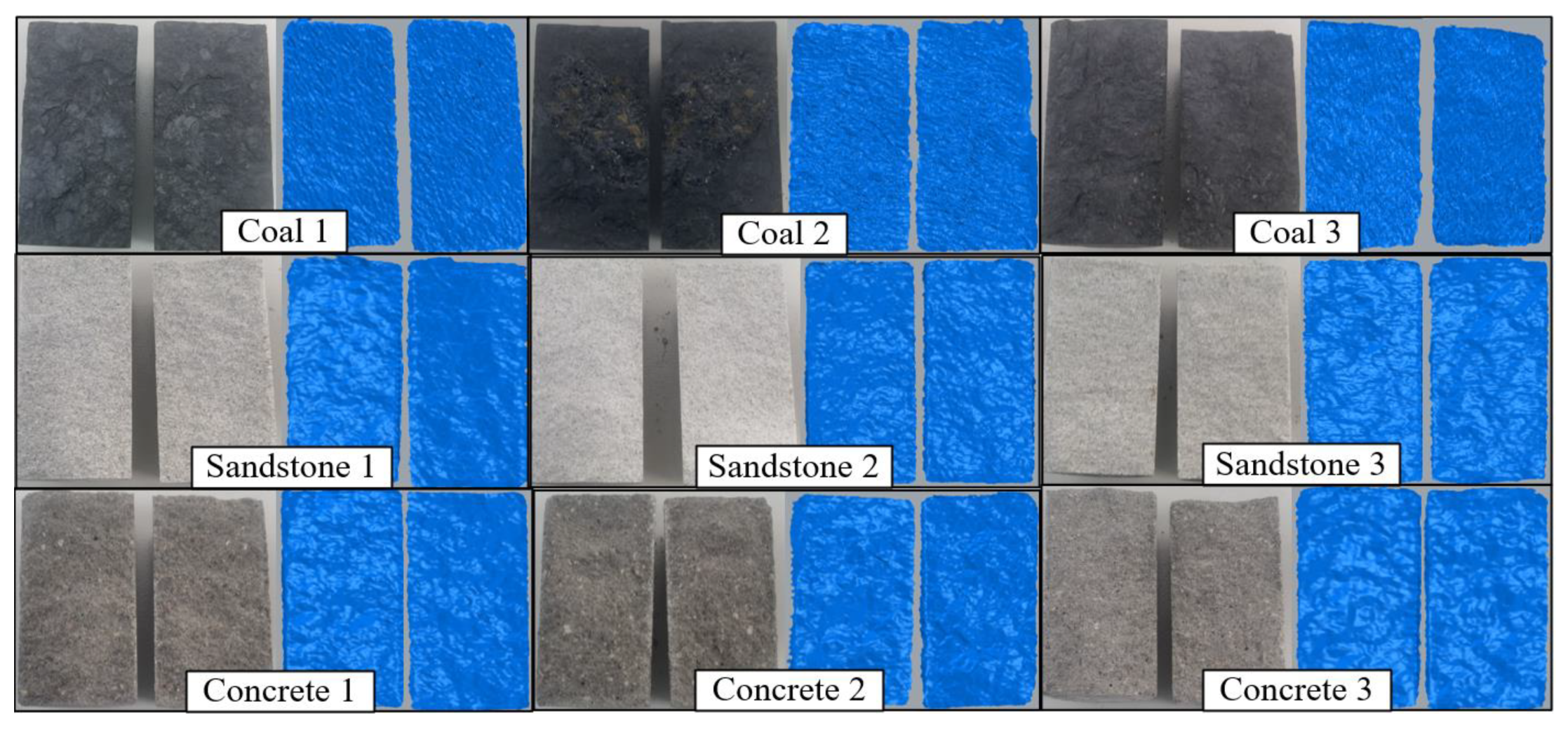
A 3D scanner was used to scan the fracture surface, obtain the 3D point cloud data of the fracture surface, and obtain the 3D model of the fracture surface through 3D reconstruction. Three pieces each of coal, sandstone, and concrete were taken for 3D scanning before and after the seepage experiment. The three-dimensional (3D) model of the sample fracture is shown in Figure 16.

Figure 16.
Three-dimensional scan of a rough fracture.
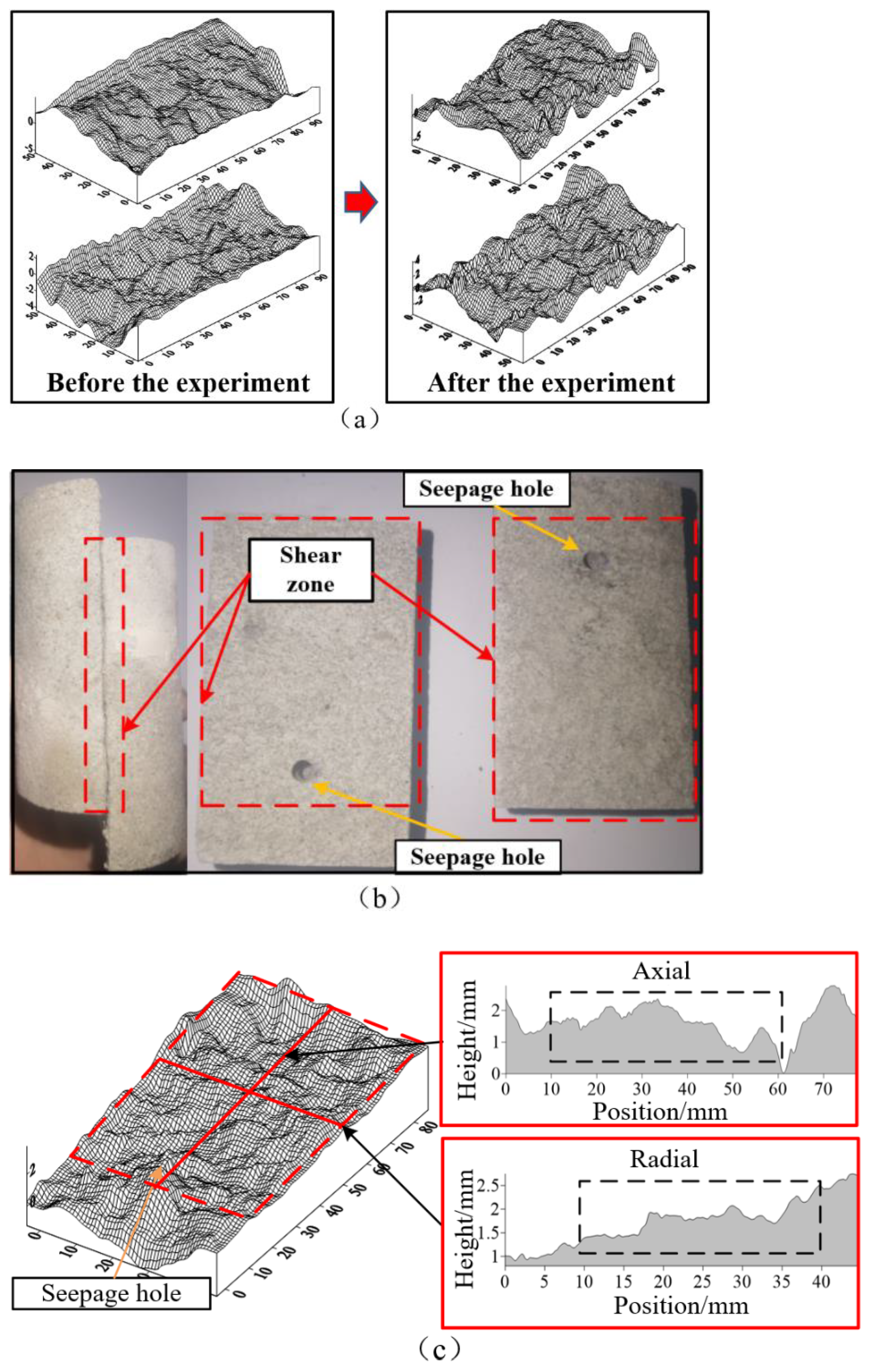
A three-dimensional (3D) wireframe and cloud maps of the fracture surface can be obtained by processing the obtained point data. A comparative analysis was carried out using the three-dimensional (3D) morphology change in the fracture surface of the sample before and after the seepage experiment, as shown in Figure 17a, in order to quantitatively analyse the change in rough fracture morphology and fracture damage characteristics under the coupling effect of shear stress–seepage erosion. One of the upper and lower fracture surfaces of the split sample was taken for analysis, which was vertically intercepted along the axial centre line and radial centre line of the fracture surface to obtain the fracture surface profile. Since the part that actually undergoes shear stress and generates shear displacement is not the entire fracture surface of the sample, but the region from the vicinity of the seepage hole to the other end of the fracture surface, it is necessary to intercept this part of the fracture surface to draw the profile contour line for analysis, as shown in Figure 17b,c.
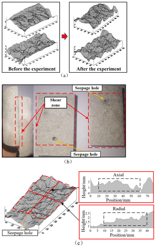
Figure 17.
Quantitative characterisation of the 3D morphology of the rough fracture. (a) Changes in rough fracture morphology before and after the test; (b) rough fracture shear region; (c) rough fracture profiles.
After the quantitative characterisation of the morphological features of the fracture surface, the roughness coefficients of the fracture surface were calculated, as shown in Table 4.
Table 4.
Fracture roughness under the coupling of shear stress and seepage erosion.
According to Figure 18a,b, under the action of shear stress, the overall trend of coal, sandstone, and concrete fracture roughness before and after the seepage experiment is decreasing, and the rough fracture surface tends to be flat. The coal sample has more obvious stratification, its shear damage is more obvious in the raised part of the fracture when subjected to shear stress–seepage erosion coupling, and part of the phenomenon of rock spalling exists, so the change in the fracture roughness of coal is more obvious. In Figure 18c,d, a comparison of coal, sandstone, concrete samples in different normal stress (peripheral pressure) under the action of the fracture roughness changes can be seen. Due to the stress–seepage coupling effect of the fracture surface of the three-bit morphology, the local fracture roughness increases, but the increase in the size of such a fracture roughness is relatively small. Comparing the two forms of stress action, the two forms of stress action and seepage coupling will make the rock mass fracture roughness decrease, but the shear stress–seepage erosion coupling for the rock mass fracture surface damage is more obvious. The damage of rock fracture is mainly controlled by shear stress, which in turn affects the seepage characteristics of the fracture to a certain extent.

Figure 18.
Changes in roughness of fracture profiles under shear stresses. (a,b) Changes in fracture roughness under shear stress; (c,d) changes in fracture roughness under normal stress.
4.3. Characterisation of Rough Fracture Damage under Hydrodynamic Coupling
Rock fractures will undergo different degrees of fracture damage under the coupling of shear stress and seepage erosion, and the damage to the fracture surface will in turn change the distribution of seepage channels, thus affecting the seepage characteristics of the fractures. The seepage of rough cracks can be roughly represented by Figure 19. The black area in the figure represents the area closed by the contact between the upper and lower surfaces of the fracture; this part of the area is almost free of voids, and there is almost no fluid flow through the fracture when seepage occurs. The white area in the figure is a non-connected void formed between the contact area of the fracture surface and the upper and lower surfaces of the fracture; this part of the area is relatively isolated when seepage occurs, and there is no fluid flow through the area. The blue area in the figure is the connected void between the upper and lower surfaces of the fracture; this part of the void is not connected when seepage occurs. This part of the void is the main water-conducting channel when seepage occurs in the fracture, that is, the seepage channel. The three-dimensional (3D) topographic scanning of the fracture can quantitatively study the topographic changes in the fracture surface and can also obtain the damage characteristics of the fracture and the evolution of the fracture seepage channel through the before-and-after comparative analysis.
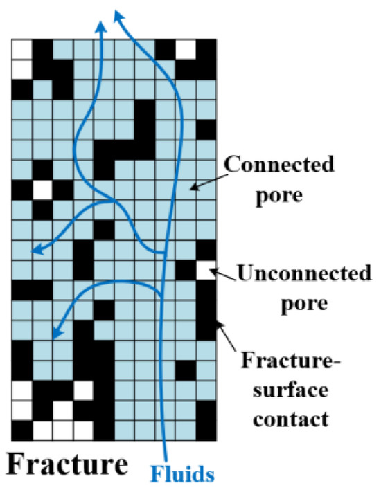
Figure 19.
Schematic diagram of seepage through rough fractures in the rock mass.
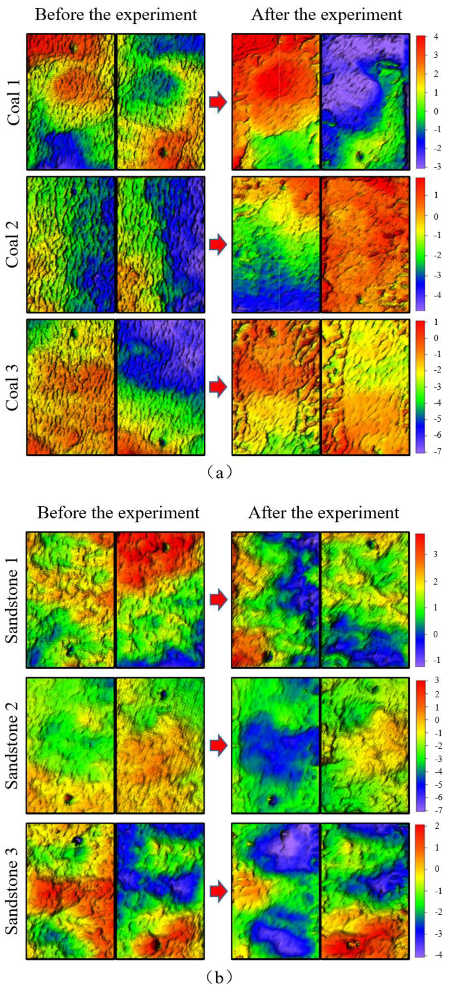
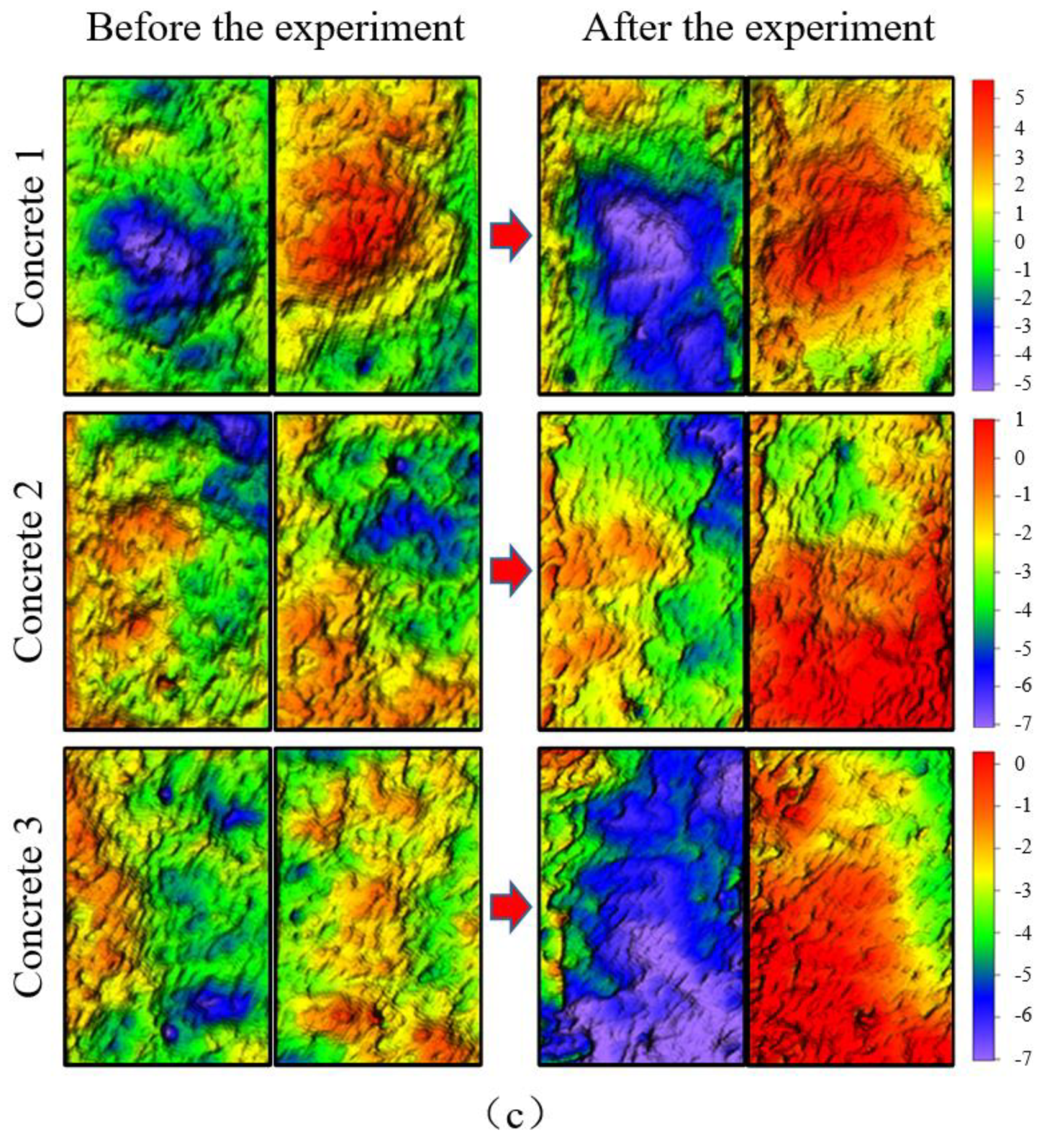
The scanning results shown in Figure 20 indicate the 3D morphology of the fracture surface before and after seepage experiments under the coupling of tangential stress and seepage erosion. The selected region for scanning corresponds to the actual shear region on the fracture surface, where the fracture experiences the combined effects of tangential stress and seepage erosion.

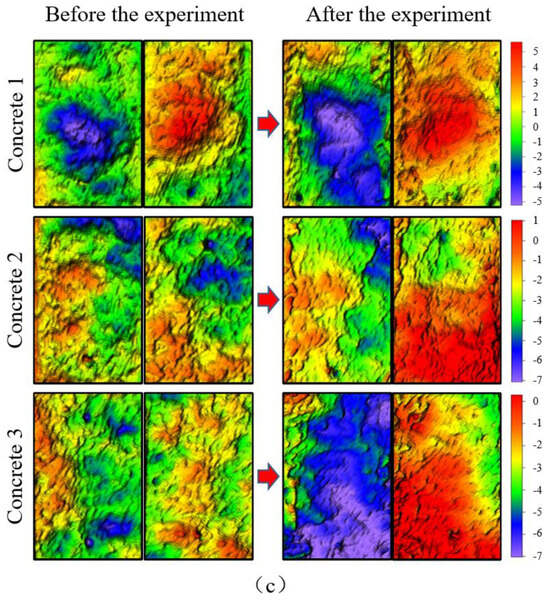
Figure 20.
Morphological cloud map of fracture shear region. (a) Coal; (b) sandstone; (c) concrete.
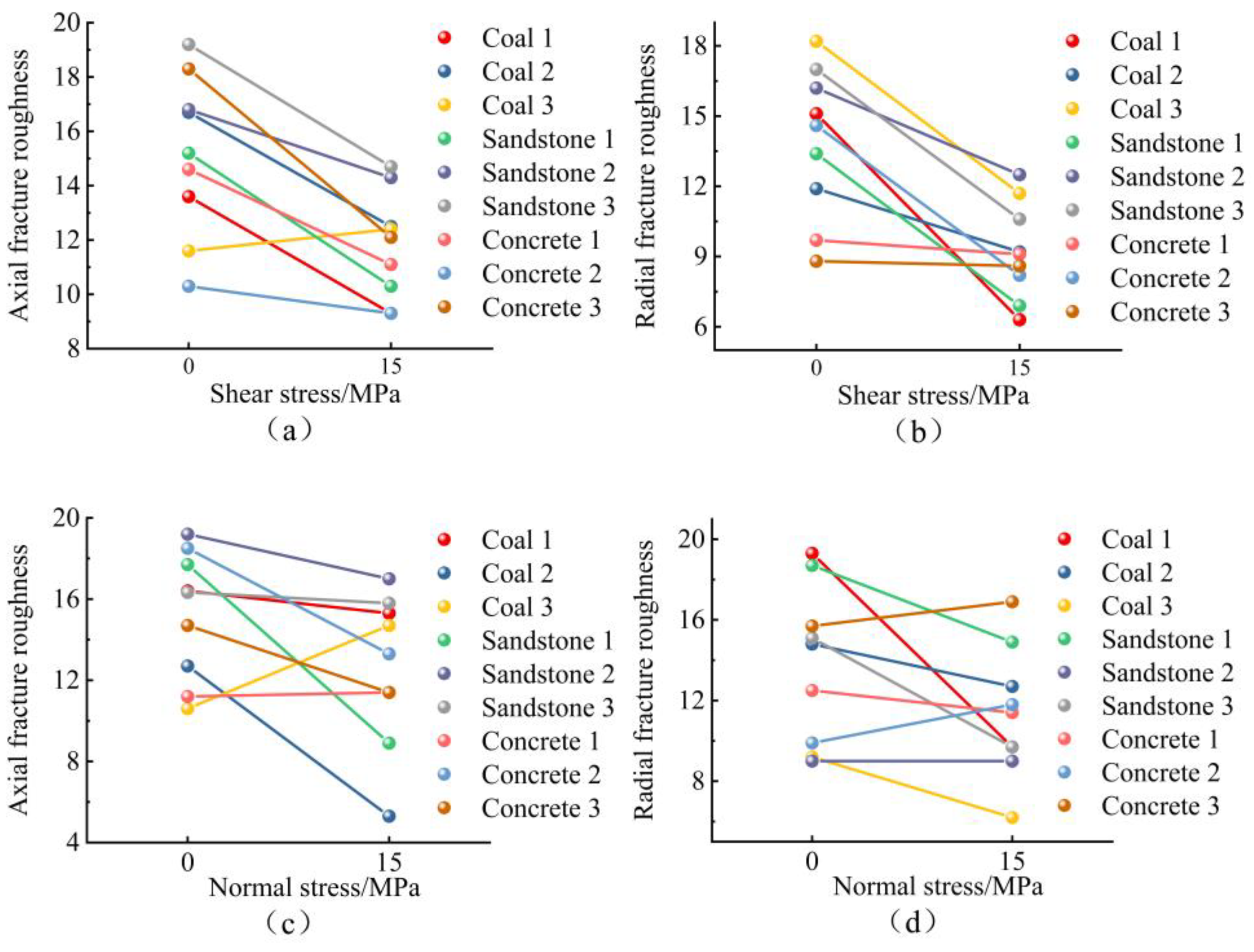
By comparing the three-dimensional (3D) morphology maps of the fracture surface before and after the shear seepage test of the sample in the figure, it can be found that the area of the fracture surface where the actual shear occurs produces a large area of fracture damage and destruction under the coupling effect of shear stress and seepage erosion, which results in the fracture protrusion in this area being sheared off and the roughness being reduced. The intuitive performance can be observed as a large area of similar elevation within the cloud map of fracture morphology. The variation in permeability characteristics of the fractured rock samples is mainly related to the morphological features of the fracture surfaces, and some scholars have studied the morphological features of rock shear surfaces to quantitatively represent the morphological features of rock fractures [31,32]. The height and texture parameters of the rough fracture surface of the rock mass were selected for statistical analysis. The height parameters include the maximum peak height of the fracture surface Sp, the maximum valley depth of the fracture surface Sv, the maximum height of the contour Sz, the arithmetic mean deviation Sa, and the root-mean-square of the height Sq, while the texture parameters include the root-mean-square of the gradient Sdq and the ratio of the unfolded interface area Sdr. Sa is the absolute mean value of the distribution height deviation from the median surface; Sq is the square root of the mean value of the sum of the squared distances from each point to the datum surface on the fracture surface contour, reflecting the discrete and fluctuating nature of the microscopic morphology; Sdq is the root-mean-square of the first-order inverse of the fracture surface contour surface, which is related to the inclined state, slope value, and contour shape of the fracture contour; and Sdr is the ratio of the true surface area of the fracture surface to the projected area of the fracture surface. One of the two fracture surfaces of each sample was taken to be analysed, and the parameters of the rough fracture morphology characteristics before and after the test were normalised. The change in fracture morphology under the coupling of shear stress and seepage erosion is shown in Figure 21, and the average rate of change of each parameter is shown in Figure 22.
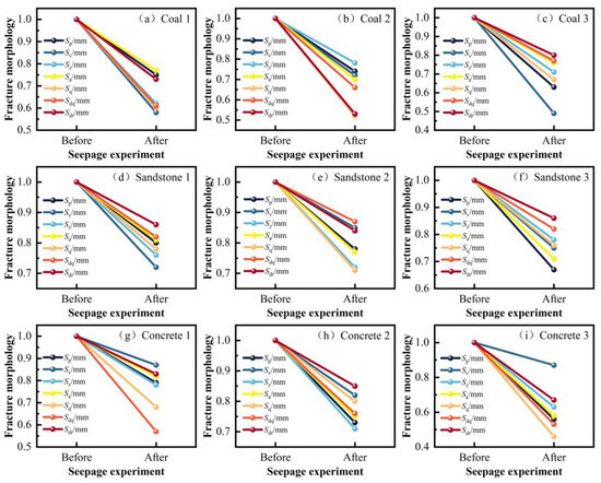
Figure 21.
Changes in fracture morphology parameters before and after seepage experiments with different samples. (a–c) Coal; (d–f) sandstone; (g–i) concrete.
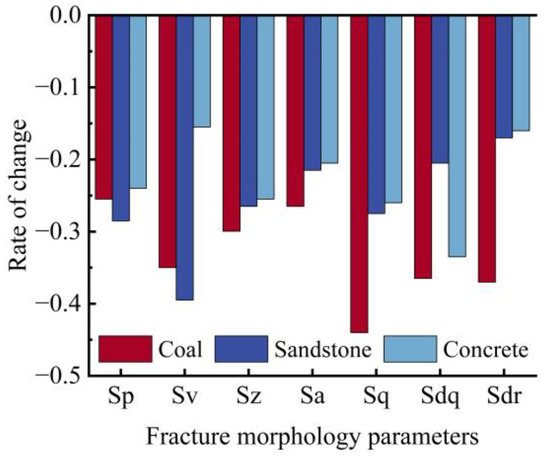
Figure 22.
Average rate of change of fracture morphology parameters for different samples.
By comparing the changes in the fracture morphology parameters before and after the seepage experiments on coal, sandstone, and concrete samples, it can be seen that the rough fracture of the samples has a large change in fracture morphology under the coupling of shear stress and seepage erosion, and the fracture damage is more obvious. The maximum peak height Sp of the fracture surface of the coal sample decreased by 25.5% on average, the root-mean-square of the height Sq decreased by 44.1% on average, and the unfolded interfacial area ratio Sdr decreased by 37.1% on average. Due to the obvious laminar structure of coal, its fracture height rms Sq and fracture slope rms Sdq varied greatly, the fluctuation and discrete nature of the fracture morphology was stronger, the fracture surface morphology of coal varied greatly, and the fracture damage was more obvious. The maximum peak height Sp on the fracture surface of sandstone samples decreased by 28.5% on average, and the maximum valley depth Sv on the fracture surface decreased by 39.5% on average, but the rest of the changes in fracture morphology parameters were relatively small. It can be seen that for sandstone, because its rock mass shear strength is larger, the rock mass particles are smaller, so before and after the seepage experiment the fracture surface morphology parameter changes are small, the fracture damage is not obvious, and there was damage only in the fracture raised part. The concrete sample has a lower shear strength, so the characteristic parameters of the height of the fracture surface change more obviously. Through the fracture shear region morphology cloud it can also be found that there is an obvious increase in damage in the raised part of the fracture surface due to shear stress and seepage pressure under the action of shear damage. Comprehensively analysing the fracture damage of each sample, it can be seen that under the same stress conditions, the fracture damage of the coal sample > the fracture damage of the concrete sample > the fracture damage of the sandstone sample.
5. Conclusions
In this study, the seepage experiments in rough fractures of coal, sandstone, and concrete samples were carried out using the gravity-loading rock seepage test platform, and the seepage patterns and morphological changes in rough fractures of rock masses under the coupling of different shear stresses and seepage and erosion were investigated in the light of the water absorption, compressive strength, shear strength, and other mechanical characteristics of coal, sandstone, and concrete. The conclusions are as follows:
- When seepage occurs within the rough fractures of coal, sandstone, and concrete, there is a nonlinear proportional increase in seepage pressure and seepage flow. Under the same stress conditions, the seepage velocity of the three materials is as follows: concrete > sandstone > coal. Due to the more obvious laminar structure of coal, it has a hindering effect on the seepage flow in the fractures. The decrease in seepage velocity in rough fractures of rock masses with larger shear strength is smaller, and the decrease in seepage velocity in rough fractures of rock masses with smaller shear strengths is larger.
- With the increase in shear stress on the sample under the same conditions of surrounding pressure and seepage pressure, the rough fracture permeability of sandstone and concrete decreases, while the permeability of coal has a significant increase. This is due to the obvious laminar nature of coal and the non-homogeneous nature of the rough fractures in the occurrence of shear slip along the direction of laminar sliding, so that the fracture openings increased and permeability increased. Under the same conditions, the permeability difference between coal and sandstone and concrete is about ten times. The effect of shear stress–seepage coupling on the rough fracture permeability of coal, which has more obvious laminations, is about two times the effect of normal stress–seepage coupling on permeability, and the form of stress action on sandstone, concrete, and this kind of rock mass has less effect.
- The mechanism of rock erosion damage under water-force coupling action is that the raised contact between the fracture surfaces of the rock mass will be sheared and broken with shear sliding, and the resulting raised broken material will roll, micro-fracture, abrade, and be spatially redistributed with shear, which in turn affects the seepage and strength characteristics of the fracture. Due to the destruction and shedding of particles in the seepage pressure driven by the transport on the fracture surface, the fracture morphology characteristics will change, as will the original seepage channel of the fracture. This part of the rock particles, when transported to the narrow area of the fracture, will produce a filling effect on the fracture. When the fracture contacts the surface extrusion, shear will exacerbate the fracture surface due to the hydrodynamic coupling of erosion damage, thus further changing the seepage characteristics of the rock mass fracture.
- Under shear stress and seepage erosion coupling, the destructive effect for the rock mass fracture morphology is significantly stronger than under the normal stress–seepage erosion phase coupling. In addition, under the same conditions, the degree of change in fracture morphology (fracture damage) of different rock masses is coal > concrete > sandstone.
- The 3D morphology scanning technique provides a better representation of the geometric features of the fractures. These data can help us to quantitatively analyse the erosion damage of rock fractures. However, there are some limitations; for example, this method can only obtain the fracture morphology data before and after the test. Real-time monitoring during the experiment cannot be completed. In addition, the stress environment in which the underground rock is located in the actual situation is very complex, and the triaxial experimental method of isoperimetric pressure cannot simulate this situation well. It is necessary to increase the study of rocks containing fractures under true triaxial conditions due to the existence of non-homogeneity and anisotropy factors within coal and some other rocks having an effect on the fracture seepage [33]. In contrast, most current coal seepage studies do not consider the dynamic changes in permeability during seepage caused by stress changes [34]. In the next step, we can consider studying the structural change and stress change of coal and exploring the dynamic change law of permeability at each stage of the seepage process under the influence of anisotropy and other factors.
Author Contributions
Q.Y and Z.S. conceived and designed the experimental programme; Q.Y., Z.S. and Y.X. derived theoretical equations; Z.S., C.W., F.W. and J.S. conducted laboratory experiments; Z.S., W.W. and C.W. collated and analysed experimental data; Z.S. wrote the paper; Q.Y. helped Z.S. revise the manuscript. All authors have read and agreed to the published version of the manuscript.
Funding
This research was funded by the Science and Technology Innovation Special Fund of Jiangsu Provincial Science and Technology Department, approval No. BK20220024, project No. 2022-12460.
Data Availability Statement
Data are contained within the article.
Conflicts of Interest
The authors declare that they have no conflict of interest.
References
- Yao, Q.; Hao, Q.; Chen, X.; Zhou, B.; Fang, J. Design of coal pillar dam width for underground reservoir in coal mine. J. Coal 2019, 44, 891–899. [Google Scholar]
- Xu, J.L.; Zhu, W.B.; Wang, X.Z. A method for predicting the height of hydraulic fracture zones based on the location of key layers. J. Coal Sci. 2012, 37, 762–769. [Google Scholar]
- Yao, Q.; Tang, C.; Liu, Z. Analysis of coal-water co-mining in ecologically fragile mines in western China. Coal Sci. Technol. 2021, 49, 225–232. [Google Scholar]
- Dazhao, G. Theoretical framework and technical system of coal mine underground water reservoir. J. Coal Sci. Technol. 2015, 40, 239–246. [Google Scholar]
- Xie, H.; Xu, W.-L.; Liu, C.; Yang, X.-G. Strategic concept and key technology outlook of underground hydraulic engineering. J. Rock Mech. Eng. 2018, 37, 781–791. [Google Scholar]
- Qiao, W.; Li, W.; Li, T.; Chang, J.; Wang, Q. Effects of Coal Mining on Shallow Water Resources in Semiarid Regions: A Case Study in the Shennan Mining Area, Shaanxi, China. Mine Water Environ. 2017, 36, 104–113. [Google Scholar] [CrossRef]
- Li, P.; Wu, J.; Tian, R.; He, S.; He, X.; Xue, C.; Zhang, K. Geochemistry, Hydraulic Connectivity and Quality Appraisal of Multilayered Groundwater in the Hongdunzi Coal Mine, Northwest China. Mine Water Environ. 2018, 37, 222–237. [Google Scholar] [CrossRef]
- Olsson, R.; Barton, N. An improved model for hydromechanical coupling during shearing of rock joints. Int. J. Rock Mech. Min. Sci. 2001, 38, 317–329. [Google Scholar] [CrossRef]
- Jing, L.; Hudson, J.A. Numerical methods in rock mechanics. Int. J. Rock Mech. Min. Sci. 2002, 39, 409–427. [Google Scholar] [CrossRef]
- Detwiler, R.L.; Rajaram, H. Predicting dissolution patterns in variable aperture fractures: Evaluation of an enhanced depth-averaged computational model. Water Resour. Res. 2007, 43. [Google Scholar] [CrossRef]
- Le Borgne, T.; Ginn, T.R.; Dentz, M. Impact of fluid deformation on mixing-induced chemical reactions in heterogeneous flows. Geophys. Res. Lett. 2014, 41, 7898–7906. [Google Scholar] [CrossRef]
- Dijk, P.E.; Berkowitz, B. Buoyancy-driven dissolution enhancement in rock fractures. Geology 2000, 28, 1051–1054. [Google Scholar] [CrossRef]
- Wu, Y.Q. Groundwater and geological hazards. Undergr. Space 1999, 4, 303–310. [Google Scholar]
- Xia, C.; Wang, W.; Cao, S. Seepage characteristics of joints under different contact states. J. Rock Mech. Eng. 2010, 29, 1297–1306. [Google Scholar]
- Fu, Y.; Wang, Z.; Liu, X.; Yuan, W.; Miao, L.; Liu, J.; Deng, Z. Study of fine-scale damage evolution and macroscopic deterioration of sandstone under dry and wet cycling. J. Geotech. Eng. 2017, 39, 1653–1661. [Google Scholar]
- Feng, X.; Wang, W.; Wang, R.; Yuan, S.; Zhu, Q. An ontological model of rheological damage in sandstone considering water chemical damage. Geotechnics 2018, 39, 3340–3346. [Google Scholar]
- Yu, J.; Zhang, X.; Cai, Y.; Liu, S.; Tu, B.X.; Fu, G.F. Experimental study on the microscopic damage and mechanical property degradation of sandstone under the combined action of water chemistry and freeze-thaw cycle. Geotechnics 2019, 40, 455–464. [Google Scholar]
- Tang, L.; Zhang, P.; Wang, S. Experimental study on the macroscopic mechanical effects of water-rock chemistry on rocks. J. Rock Mech. Eng. 2002, 21, 526–531. [Google Scholar]
- Brush, D.J. Three-Dimensional Fluid Flow and Solute Transport in Rough-Walled Fractures. Ph.D. Thesis, University of Waterloo, Waterloo, ON, Canada, 2001. [Google Scholar]
- Shen, L.F.; Feng, X.T.; Pan, P.C.; Zhou, F. Experimental study of single-fissure granite under stress-seepage-chemistry coupling. J. Rock Mech. Eng. 2010, 29, 1379–1388. [Google Scholar]
- Jiang, Z.-B.; Jiang, J.-N.; Li, H. Changing law of permeability characteristics of slate through fissures in corrosive environment. J. Coal Sci. 2016, 41, 1954–1962. [Google Scholar]
- Wu, Y.; Lin, Y.; Wan, J.; Wang, Z.J. Coupled seepage-erosion model for carbonate rocks with single fissure and sensitivity analysis of its parameters. China Karst 2016, 35, 81–86. [Google Scholar]
- Hudson, J.A.; Cornet, F.H.; Christiansson, R. ISRM suggested methods for rock stress estimation-part 1: Strategy for rock stress estimation. Int. J. Rock Mech. Min. Sci. 2003, 40, 991–998. [Google Scholar] [CrossRef]
- Kou, M.M.; Liu, X.R.; Wang, Z.Q.; Tang, S.D. Laboratory investigations on failure, energy and permeability evolution of fissured rock-like materials under seepage pressures. Eng. Fract. Mech. 2021, 247, 27. [Google Scholar] [CrossRef]
- Zhao, J. Applicability of Mohr–Coulomb and Hoek–Brown strength criteria to the dynamic strength of brittle rock. Int. J. Rock Mech. Min. Sci. 2000, 37, 1115–1121. [Google Scholar] [CrossRef]
- Huang, S.; Xia, K.; Dai, F. Establishment of a Dynamic Mohr-Coulomb Failure Criterion for Rocks. Int. J. Nonlinear Sci. Num. 2012, 13, 55–60. [Google Scholar] [CrossRef]
- Singh, M.; Singh, B. Modified Mohr-Coulomb criterion for non-linear triaxial and polyaxial strength of jointed rocks. Int. J. Rock Mech. Min. Sci. 2012, 51, 43–52. [Google Scholar] [CrossRef]
- Snow, D.T. Anisotropie Permeability of Fractured Media. Water Resour. Res. 1969, 5, 1273–1289. [Google Scholar] [CrossRef]
- Zhao, Z. Gouge Particle Evolution in a Rock Fracture Undergoing Shear: A Microscopic DEM Study. Rock Mech. Rock Eng. 2013, 46, 1461–1479. [Google Scholar] [CrossRef]
- Du, S.G.; Chen, Y.; Fan, L.B. Mathematical expression of the JRC modified straight edge method. J. Eng. Geol. 1996, 4, 36–43. [Google Scholar]
- Deng, H. Mechanisms of loading rate effect on tensile strength of sandstone. Geotechnics 2018, 39, 79–88. [Google Scholar]
- Xu, J.; Wang, W.; Liu, Y.; Peng, S.; Wu, S.; Qu, J.; Xiao, Z. Experimental study on morphological characteristics of coal rock shear section under shear-seepage action. Geotechnics 2018, 39, 4313–4324. [Google Scholar]
- Menezes, F.F. Anisotropy of volume change and permeability evolution of hard sandstones under triaxial stress conditions. J. Pet. Sci. Eng. 2019, 174, 921–939. [Google Scholar] [CrossRef]
- Zhao, Y.; Lin, B.; Liu, T.; Li, Q.; Kong, J. Gas flow field evolution around hydraulic slotted borehole in anisotropic coal. J. Nat. Gas Sci. Eng. 2018, 58, 189–200. [Google Scholar] [CrossRef]


Disclaimer/Publisher’s Note: The statements, opinions and data contained in all publications are solely those of the individual author(s) and contributor(s) and not of MDPI and/or the editor(s). MDPI and/or the editor(s) disclaim responsibility for any injury to people or property resulting from any ideas, methods, instructions or products referred to in the content. |
© 2023 by the authors. Licensee MDPI, Basel, Switzerland. This article is an open access article distributed under the terms and conditions of the Creative Commons Attribution (CC BY) license (https://creativecommons.org/licenses/by/4.0/).