Article

A Turbulent Mass Diffusivity Model for Predicting Species Concentration Distribution in the Biodegradation of Phenol Wastewater in an Airlift Reactor

National Engineering & Technological Research Center for Industry Water Treatment, CNOOC Tianjin Chemical Research & Design Institute, Tianjin 300131, China
*
Author to whom correspondence should be addressed.
Processes 2023, 11(2), 484; https://doi.org/10.3390/pr11020484
Submission received: 3 December 2022 / Revised: 21 January 2023 / Accepted: 2 February 2023 / Published: 6 February 2023

Abstract

:
In this study, a three-dimensional CFD transient model is established for predicting species concentration distribution in the biodegradation of phenol in an airlift reactor (ALR). The gas–liquid flow in the ALR is determined by the Euler–Euler method coupled with the standard k-ε model, and the bubble size is predicted by the population balance model (PBM). A turbulent mass diffusivity model is developed to simulate the turbulent mass transfer process and to predict the species concentration distribution. No empirical methods are needed as the turbulent mass diffusivity can be expressed by the concentration variance c 2 ¯ and its dissipation rate εc. A good agreement is found between simulated and experimental results in the literature. It is not reasonable to assume a constant turbulent Schmidt number because the calculated distribution of turbulent mass diffusivity is not identical to that of turbulent viscosity. Finally, the hydrodynamic characteristics and biodegradation performance of the proposed model in a novel ALR are compared with that in the original ALR.

1. Introduction

Airlift reactors (ALRs) are multiphase reactors that are widely used in the chemical, environmental, and biochemical industries [1]. In an ALR, the fluid flow region is divided into a downcomer and riser by the draft tube at the center of the reactor [2,3]. The gas phase enters through a gas sparger at the bottom of the ALR, an upward flow of the gas and liquid phases occurs in the riser, and a downward flow of the liquid phase occurs in the downcomer. Generally, no gas enters the downcomer as the superficial gas velocity is low, but as the increase of superficial gas velocity, more gas would be brought into the downcomer by the liquid phase. The density difference between the riser and the downcomer would provide a driving force for the circulation of the liquid in the ALR. ALRs have attracted considerable attention in recent years due to their excellent mixing performance, low cost, low power input, and homogeneous shear stress distribution. Compared to bubble columns, ALRs can offer a more favorable culture condition for microorganisms that are susceptible to fluid turbulence-induced damage [4,5].
As one of the major organic pollutants, phenol can be found in the effluent from pharmaceutical, plastic, petrochemical, and explosive manufacturing industries [6], and it has potential environmental and health consequences even at low concentrations [7]. At present, biological degradation is the most common method to treat low-concentration phenolic pollutants in wastewater because of its low cost, low risk of secondary pollution, and high treatment efficiency and capacity [8]. The unique advantages of ALRs, such as high mass and heat transfer rate, low operating cost, and homogeneous shear stress distribution, make them an attractive option in the biological treatment process. Patil et al. studied the biodegradation of diethyl phthalate by the mixture of Micrococcus sp.KS2 and Bacillus sp.KS1 in an ALR, and they found that the ALR was capable of degrading diethyl phthalate up to 1500 mg/L [9]. Livingston et al. treated 3,4-dichloroaniline wastewater in a three-phase ALR, the microorganisms were immobilized onto earth particles, 95% degradation efficiency was obtained, and a mathematical model was established to describe the diffusion and reaction processes in the reactor [10]. Gholamia et al. developed a novel jet ALR that could provide regions with different oxidation-reduction potentials, and thus nitrogen and carbon could be simultaneously and effectively removed from soft drink wastewater in a single piece of equipment [11]. Feng et al. established a computational fluid dynamic model for the bio-treatment of phenol using yeast candida tropicalis in an ALR and explored the impact of gas–liquid flow characteristics on biodegradation behaviors [12]. Wen et al. investigated the biodegradation process of airborne toluene in a gas–liquid–solid ALR contacting immobilized cells. The results showed that the immobilized ALR had a good performance to tolerate shock loads and the maximum elimination capacity of toluene was higher than the ALR with free microorganisms [13].
Some characteristic parameters of the ALR, such as liquid circulation velocity, gas bubble size, gas hold up, interfacial area, and shear stress distribution should be known in order to optimize and scale up its structure. Currently, it remains difficult to characterize the complex multiphase flow induced by the dispersed phase in the ALR [14,15]. Lu et al. studied the hydrodynamic characters in a laboratory scale ALR by the experimental method, the velocity field was measured by using the particle image velocimetry technique, and the bubble size distribution was obtained by digital image analysis. The experimental results showed that the liquid flow had an unsteady structure and the wake oscillation of the bubble was asymmetrical, as the superficial gas velocity increased, the probability density function curve of bubble size changed from unimodal to bimodal [16]. Luo and Al-Dahhan adopted the CARPT technique to measure the distributions of liquid velocity, turbulent kinetic energy, and gas holdup in an ALR and observed that as the increase of the superficial velocity, the flow regime would change from bubbly flow to churn-turbulent flow [2]. Sarkela et al. investigated the mixing performance of an ALR with helical flow promoters, the pH tracer method was used for the measurement of mixing time, circulation time, and axial dispersion. The experimental results showed that the sparger aeration rate had a significant effect on the mixing efficiency, the mixing time would be shorter with the increase of the aeration rate, and the mass transfer performance of the ALR with helical flow promoters is better than that of the regular ALR [17].
It is worth noting that the correlations obtained by experiments are usually system-specific and thus less useful for some operating conditions [18]. Computational fluid dynamics (CFD) is useful for investigating complex flow and mass transfer in the ALR, and it provides detailed information on the flow and species concentration fields by solving a set of differential equations [19,20]. There are two main models used for simulating the multiphase flow in the ALR. In the Euler–Euler (E–E) model, the gas, and liquid phases are regarded as the interpenetrating continua and their motion are described by solving a set of Navier–Stokes equations. In the Euler–Lagrange (E–L) model, the gas phase is treated as individual particles and the liquid phase is treated as continuous fluid. Because every bubble is tracked in the E–L model, so it would cost much more computing resources than the E–E model. There is a growing interest in CFD simulations of the biological and chemical processes in the ALR. Wang et al. adopted CFD to simulate the biodegradation of toluene emissions in ALR, and its rate-limiting step was determined based on the relationship between mass transfer rate and bioreaction [3]. Huang et al. established a steady E–E model to characterize mass transfer and hydrodynamics in the direct coal liquefaction process in an ALR [21]. Kouzbour et al. proposed a three-dimensional CFD model to simulate the reactive flow in an ALR for removing Mn(II) from drinking water by aeration, which could correctly describe the autocatalytic effect of MnO2 on oxidation [22]. Mavaddat et al. investigated the hydrodynamics and production process of polyhydroxybutyrate in an ALR by using the CFD method, and in order to account for the effect of bubble coalescence and breakup phenomenons on the interfacial mass transfer process, a population balance model was adopted [23].
The turbulent mass diffusivity Dt should be known to predict the mass transfer process in ALR. In the studies mentioned above, Dt is obtained by experiments or assuming that the turbulent Schmidt number (Sct) is fixed. In the biodegradation of wastewater in an ALR, the prediction of the distribution of species concentration is often simplified and case-specific. Sun et al. proposed a theoretical model to calculate Dt in a distillation column by solving the auxiliary concentration variance and its dissipation rate equations [24], and it has been successfully used for simulating the turbulent mass transfer process in adsorption columns [25], circulating fluidized beds [26], and bubble columns [27].
This study proposes a three-dimensional CFD model for simulating the biodegradation of phenol in an ALR. The multiphase flow is simulated by the E–E model. The turbulence effect is calculated by the standard k-ε model and the distribution of bubble size is described by the population balance model. The c 2 ¯ c model is adopted to enclose the turbulent mass transfer equations so that the distribution of species concentration in the ALR can be obtained by theoretical methods. Finally, the hydrodynamic characteristics and biodegradation performance of the proposed model in a novel ALR are compared with that in the original ALR.

2. Simulated Case

The bioreactor simulated in this work is a rectangle ALR reported by Feng et al. [12], where the cross-section of the outer column is 0.2 m × 0.2 m, and the liquid level is 0.6 m. A draft tube is fixed coaxially to the column and 50 mm above the column bottom and it is 0.14 m × 0.14 m × 0.45 m. A square gas distributor of 50 mm in width is fixed at the center of the column bottom (see Figure 1a). The air acts as the gas phase and the phenol wastewater with biomass acts as the liquid phase. The air enters the ALR through a gas distributor and is released from the top of the ALR. The airflow rate is measured by a rotor flowmeter. The range of the superficial gas velocity is 0.01 to 0.02 m/s, which could ensure the dissolved oxygen is excessive for the biodegradation process. The local gas holdup is measured by a conductivity probe, the output signals are acquired by using an A/D converter, and the data after digitization are stored and analyzed by a computer. As the superficial gas velocity is low, the gas fraction in the gas–liquid flow is lower than 20%, so the liquid velocity distributions are measured by an LDA system.
The phenol in wastewater can be degraded by using the microorganism yeast candida tropicalis, and the biodegradation products are CO2, H2O, and microbial cells. The batch biodegradation experiments are carried out in the ALR, the initial concentrations of phenol are 800 to 1600 mg/L, and the initial concentrations of cells are 34 to 102 mg/L. The temperature is maintained at 30 °C, and the initial pH of the liquid phase is 6.0. The liquid phase is sampled periodically to measure the concentrations of phenol and cells. The concentration of phenol is determined by high-performance liquid chromatography. The proposed model is verified by experimental results.
Additionally, a novel structure of ALR is proposed and the hydrodynamics and biodegradation behaviors are also characterized (see Figure 1b). The outer cylinder is 0.24 m in diameter and the liquid level is kept at 0.6 m. The outer cylinder has six cylindrical draft tubes of 0.05 m in diameter and 0.45 m in height. Six circular gas distributors of 0.03 m in diameter are installed at the ALR bottom. The draft tubes are fixed 0.03 m above the gas distributors coaxially.

3. Model Equations

The proposed model for predicting the biodegradation of phenol in wastewater assumes (1) uniform initial cell and phenol concentrations in the liquid phase; (2) as the size of the cell is small and the density of the cell is close to the culture medium, the cells, and culture medium are regarded as one phase; (3) the biodegradation and cell growth processes are only limited by cell and phenol concentrations in the liquid phase without considering other nutrients, such as oxygen and mineral salts.

3.1. Continuity Equations

As the quantity of oxygen mass transfer between gas and liquid phases is very small, the influence of interphase mass transfer on the mass balance can be negligible; the continuity equation is given below:
( α k ρ k ) t + · ( α k ρ k u k ) = 0
where k represents the phase (G: gas phase; L: liquid phase) of interest, ρ represents the density, α represents the phase volume fraction, and u represents the velocity vector.

3.2. Momentum Conservation Equations

The momentum conservation equation is given below:
t ( α k ρ k u k ) + · ( α k ρ k u k u k ) = α k p + α k ρ k g + · [ α k μ k , e f f ( u k + ( u k ) T 2 3 I u k ) ] + M k
where μk,eff is the effective viscosity consisting of the turbulence-induced viscosity μt and the molecular viscosity μlam, and p is the pressure. μt can be calculated by:
μ t = C μ ρ k 2 ε
The standard k-ε model is used to model the turbulence. Mk in Equation (2) accounts for the liquid–gas interfacial forces, including the lift force, drag force, and turbulent dispersion force. The drag force is caused by viscous stress and pressure distribution around the moving bubble in the liquid phase, which plays a major role in the interfacial forces [28]. The lift force arises from the rotation of the bubble in the liquid phase, which is perpendicular to the relative velocity. This study considers only drag and lift forces:
M L = M G = M L D + M L L
where the superscript L is the lift force and the superscript D is the drag force, which are calculated as follows:
M L D = 3 4 C D d 32 α G ρ L | u G u L | ( u G u L )
M L L = α G ρ L C L ( u G u L ) × ( × u L )
where d32 is the Sauter bubble diameter, CL is the lift coefficient (CL = 0.5 in this study) [3], and CD is the drag coefficient, which is related to the flow structure and liquid property and is calculated as follows [29]:
C D = 24 ( 1 + 0.15 R e 0.687 ) / R e     R e < 1000 C D = 0.44                                       R e > 1000

3.3. Bubble Size Distribution (PBM)

As the interfacial area depends strongly on the bubble size distribution as a result of bubble coalescence and breakup, the distribution of bubble size is expected to have an impact on the hydrodynamic and mass transfer process. Here, we adopt PBM [24] to predict the distribution of bubble size, and the class method described by Troshko and Zdravistch [30] and Zhang et al. [31] is used to solve the model equations. In this study, the bubble population of 1.2~12.5 mm in diameter is divided into ten classes and each class can be described by the following expression:
t ( α G ρ G f j ) + · ( α G ρ G u G f j ) = S j
where Sj is the source term related to bubble breakup and coalescence, and fj is the volume fraction of bubble class j:
S j =     m n m , n v j 1 ( v m + v n ) v j + 1 ( 1 1 2 δ m , n ) η c ( v m , v n ) α G f m v m α G f n v n v j α G f j     M m = 1 c ( v j , v m ) α G f m v m +     M m = j γ j , m b ( v m ) α G f m v m v j b ( v j ) α G f j
where c(vm,vn) and b(vj) are the frequencies of bubble coalescence and breakup. Several mechanisms have been proposed to describe the bubble coalescence process, such as turbulent fluctuation, wake effect, eddy capture, and so on. In this work, only the turbulent fluctuation is considered and c(vm,vn) is determined by the model of Luo et al. [32]. The turbulent collision between bubbles and turbulent eddies is considered the major contributor to bubble breakup, and the b(vj) is calculated by the model of Luo et al. [33]. Then, the equation for the Sauer bubble diameter d32 is:
1 d 32 = 10 j = 1 ( f j d j )
where dj represents the diameter of each class.

3.4. Species Conservation Equations

The concentration of phenol and biomass is indicated by the mass fraction C ¯ .
t ( ρ L α L C L i ¯ ) + · ( ρ L α L u L C L i ¯ ) = · ( ρ L α L ( D L i + D L , t i ) C L i ¯ ) + S i
t ( ρ L α L C L x ¯ ) + · ( ρ L α L u L C L x ¯ ) = S x
where the superscripts i and x represent phenol and biomass, respectively. Di and D t i represent the molecular and turbulent mass diffusivity, respectively:
D t i = C c 0 k ( k c i 2 ¯ ε ε c i ) 0.5
The concentration variance c i 2 ¯ and concentration variance dissipation rate εci are calculated as follows [34,35]:
t ( α L ρ L c i 2 ¯ ) + · ( α L ρ L u L c i 2 ¯ ) = · [ α L ρ L ( D L i + D L , t i σ c ) c i 2 ¯ ] + 2 α L ρ L C L i ¯ C L i ¯ 2 α L ρ L ε c i
t ( α L ρ L ε c i ) + · ( α L ρ L u L ε c i ) = · [ α L ρ L ( D L i + D L , t i σ ε c ) ε c i ] + C c 1 α L ρ L C L i ¯ C L i ¯ ε c i c i 2 ¯ C c 2 α L ρ L ε c i 2 c i 2 ¯ C c 3 α L ρ L ε L ε c i k L
where σc = 1.0, σεc = 1.0, Cc0 = 0.11, Cc1 = 1.80, Cc2 = 2.20, and Cc3 = 0.80 [27].

3.5. Microbial Kinetics

S in Equations (11) and (12) is the source term related to bioreaction (S = αLr). The bioreaction rates of phenol ri and biomass rx are calculated by:
r x = d ρ L C L x ¯ d t = μ m a x p L C L i ¯ K s + p L C L i ¯ + ( P L C L i ¯ ) 2 / K I × ρ L C L x ¯
r i = d ρ L C i ¯ d t = 0.823 r x + 0.277 ρ L C L x ¯
The model constants (μmax = 0.48 h−1, KI = 207.9 g/m3, and Ks = 11.7 g/m3) are determined by the batch experiments of Feng et al. [12].

4. Simulation Setup

The above differential equations are solved using Ansys Fluent 19 transient solver by the finite volume method. The velocity and pressure are coupled using the SIMPLE algorithm. The second-order discretization method is considered for the differential equations and the convergence is obtained when all the scaled residuals reached a minimum of 10−4. The velocity inlet condition is prescribed to the ALR gas distributor. The gas-phase velocity is specified based on experimental conditions. The degassing condition is prescribed to the outlet of the ALR [6,36]. A no-slip condition is ascribed to the walls for both gas and liquid phases. The initial values for c 2 ¯ and εc are described as follows [26]:
c 2 ¯ = ( 0.082 C i n ¯ ) 2 , ε c = 0.73 ( ε k ) c 2 ¯
where C i n ¯ is the initial liquid-phase phenol concentration.
After the grid independence tests, a structured mesh system with 37,328 cuboids for the rectangle ALR and a structured mesh system with 58,636 hexahedrons for the cylinder ALR with six cylindrical draft tubes are adopted in simulations, and the schematic view of the grids is displayed in Figure 2.

5. Results and Discussion

In this section, the developed CFD-coupled model was first employed to evaluate the hydrodynamic and mass transfer performance of rectangle ALR. The CFD-coupled model was validated by the comparison of the simulation results and experimental data in terms of gas holdup, liquid velocity, cell concentration, and dissolved phenol concentration. Additionally, the Sauter mean bubble diameter, shear stress, and turbulent mass diffusivity were investigated. The validated model was also employed to study the effect of the structures of ALRs on the hydrodynamic performance.

5.1. The Hydrodynamic and Mass Transfer Performance of Rectangle ALR

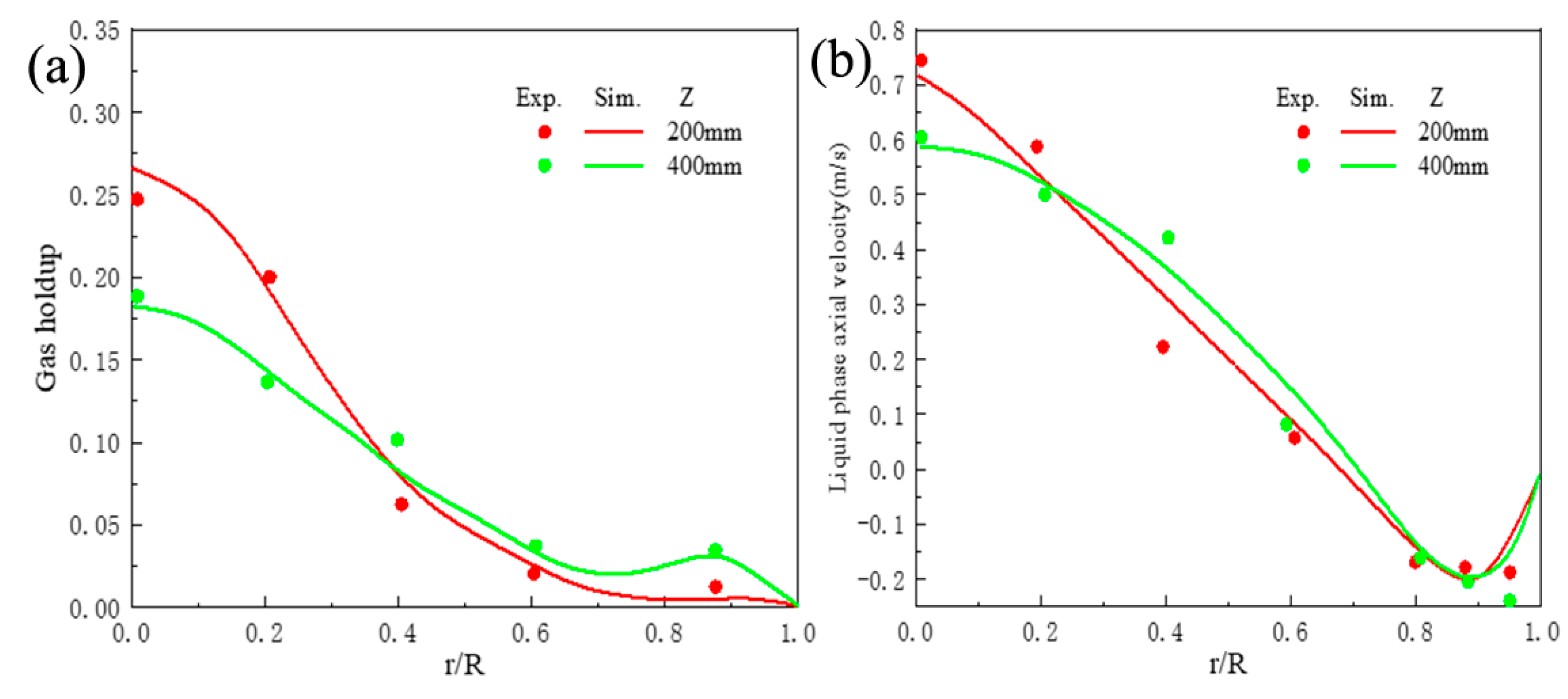
Figure 3a displays the radial profiles of simulated time-averaged gas holdup when the superficial gas velocity is 0.02 m/s, where r is the distance from the ALR axis, R is 0.1 m, and Z is the ALR height. As can be seen, the simulated results agree well with the experimental data. Generally, the gas holdup is maximized at the center of the riser. As the height increased, the profiles become flatter. Specifically, the gas holdup in the riser decreases and it meets an increase in the downcomer. The simulated time-averaged liquid velocities are compared with experimental results, as shown in Figure 3b. It is also found that the profiles obtained at different axial positions become flatter with increasing ALR height, and the negative liquid velocities in the downcomer indicate downward flow directions there. From Figure 3, the simulation results agree well with the experimental data of the gas–liquid two-phase flow, thus validating the proposed CFD coupled model.
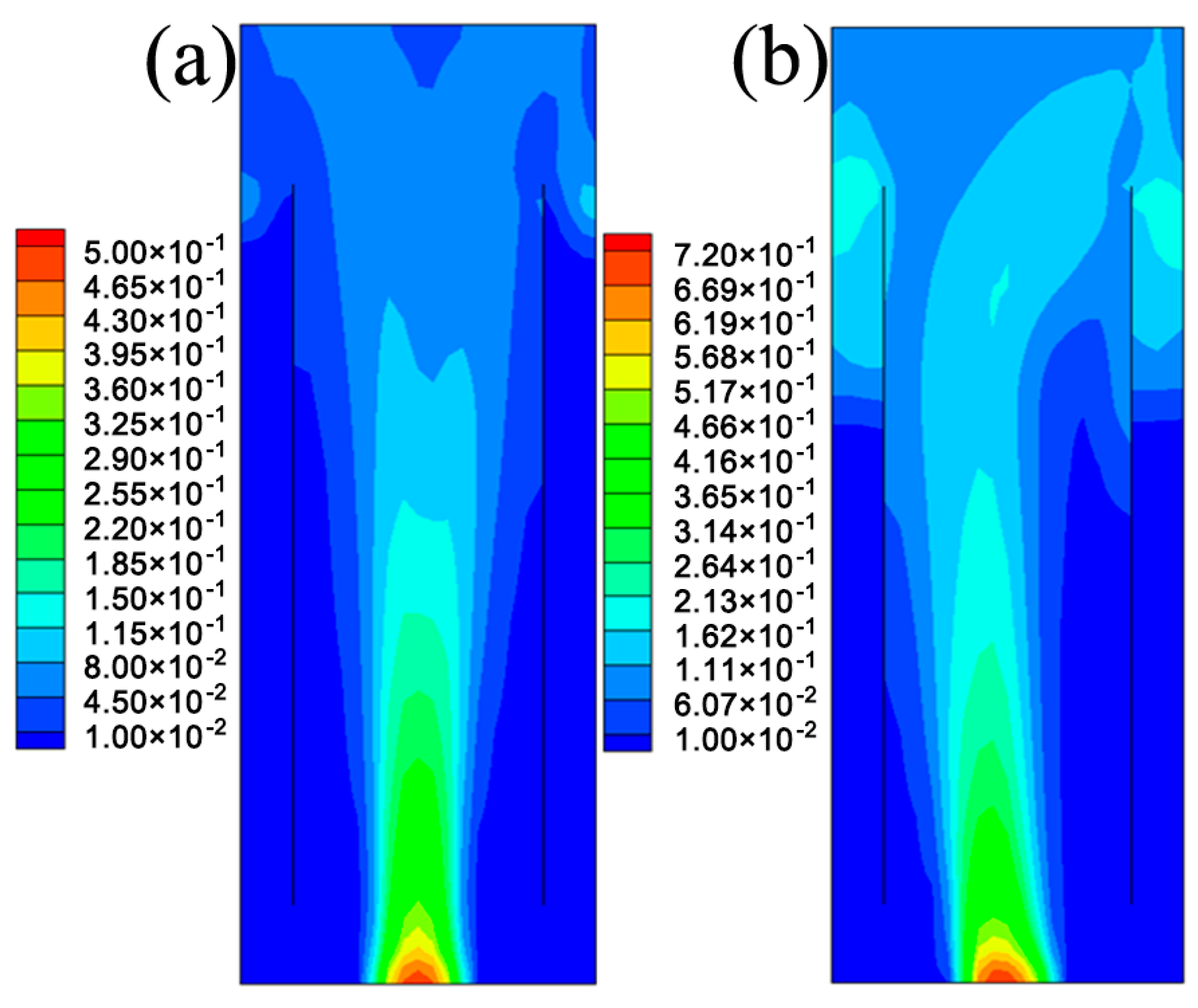
Figure 4 displays the contours of gas holdup in the ALR when the superficial gas velocity is 0.01 m/s and 0.02 m/s, respectively. It is seen in Figure 4 that a high superficial gas velocity is responsible for the high gas holdup in the ALR and more gas bubbles could be kept in the downcomer. However, it is noted that the gas holdup is still very low in the lower downcomer, indicating that no recirculation of the gas phase is formed.
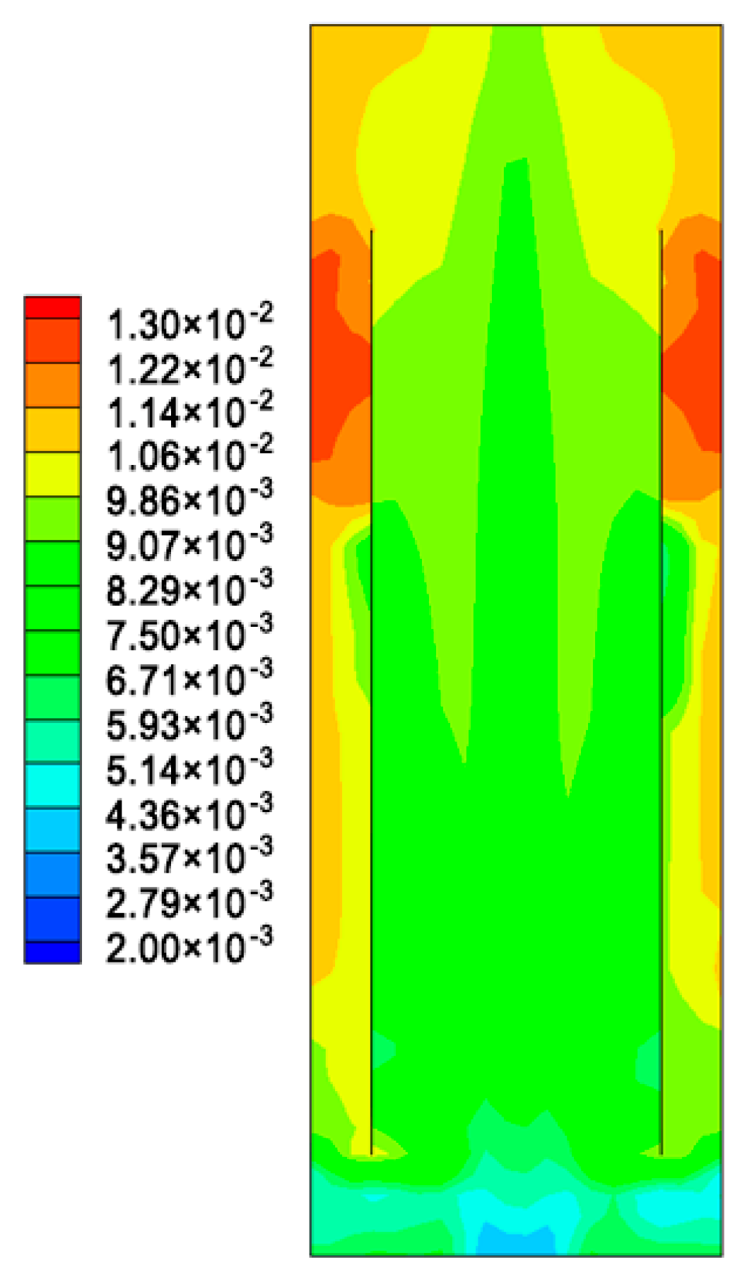
Figure 5 reveals that the bubble diameter increases with the increase of ALR height and larger bubbles are observed in the upper downcomer. That is because no gas bubble recirculation is formed between the riser and downcomer, and bubble coalescence would be more pronounced in the upper downcomer.
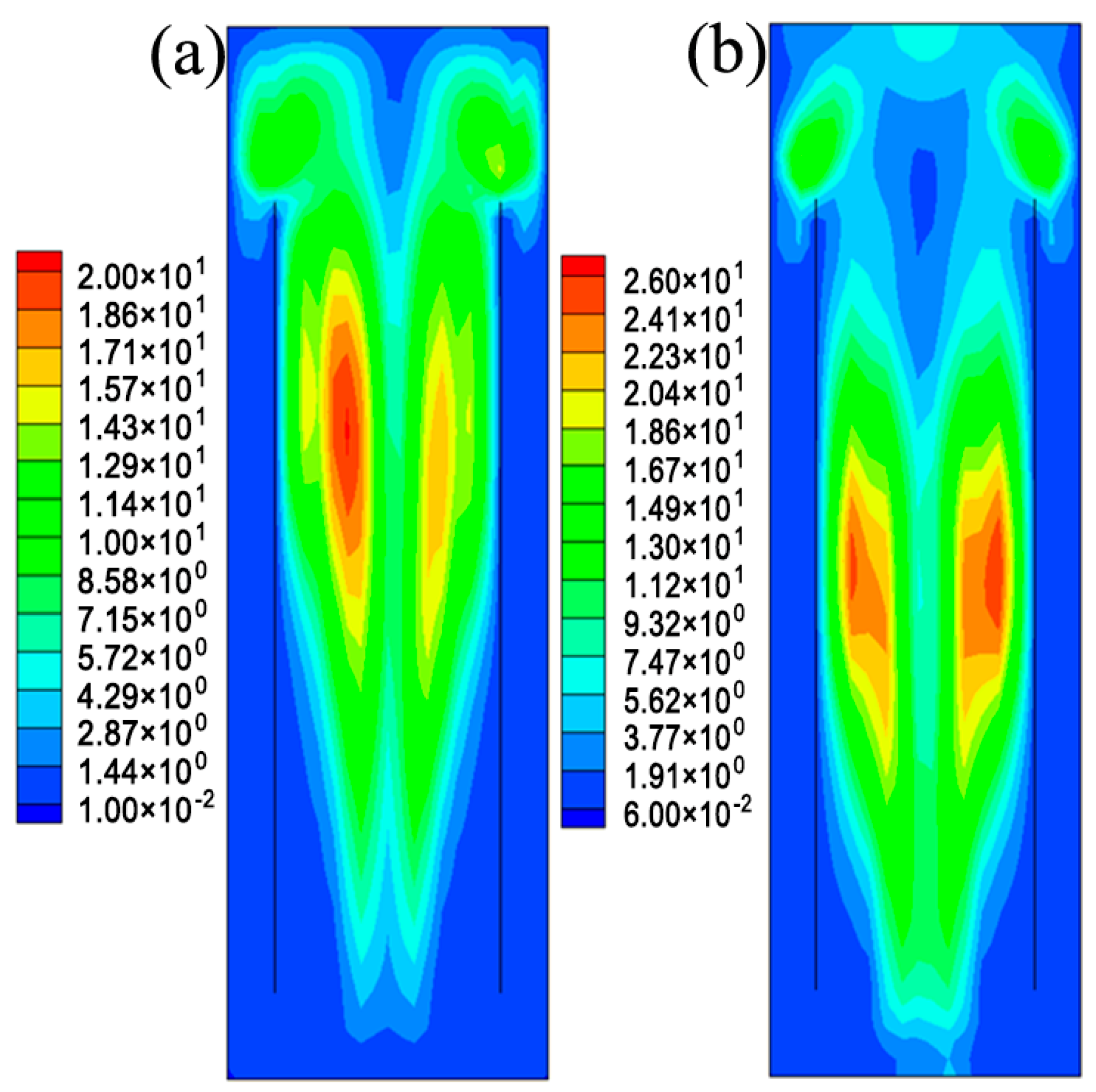
In the biodegradation process, most species of microorganisms are shear stress sensitive, and high shear stress would damage the cell morphology and reduce the reaction efficiency. So the shear stress distribution has been suggested to have an impact on microbial cultivation and thus it should be seriously considered in the design of ALR [37]. Figure 6 displays the calculated distributions of the shear stress in the ALR. The shear stress is found to increase as the superficial gas velocity increases and the maximum appears at the middle of the riser, implying the formation of a liquid-phase eddy. The shear stress in this downcomer is much smaller than that in the riser because of the very low gas holdup in the downcomer and the gas–liquid interaction should be negligible.
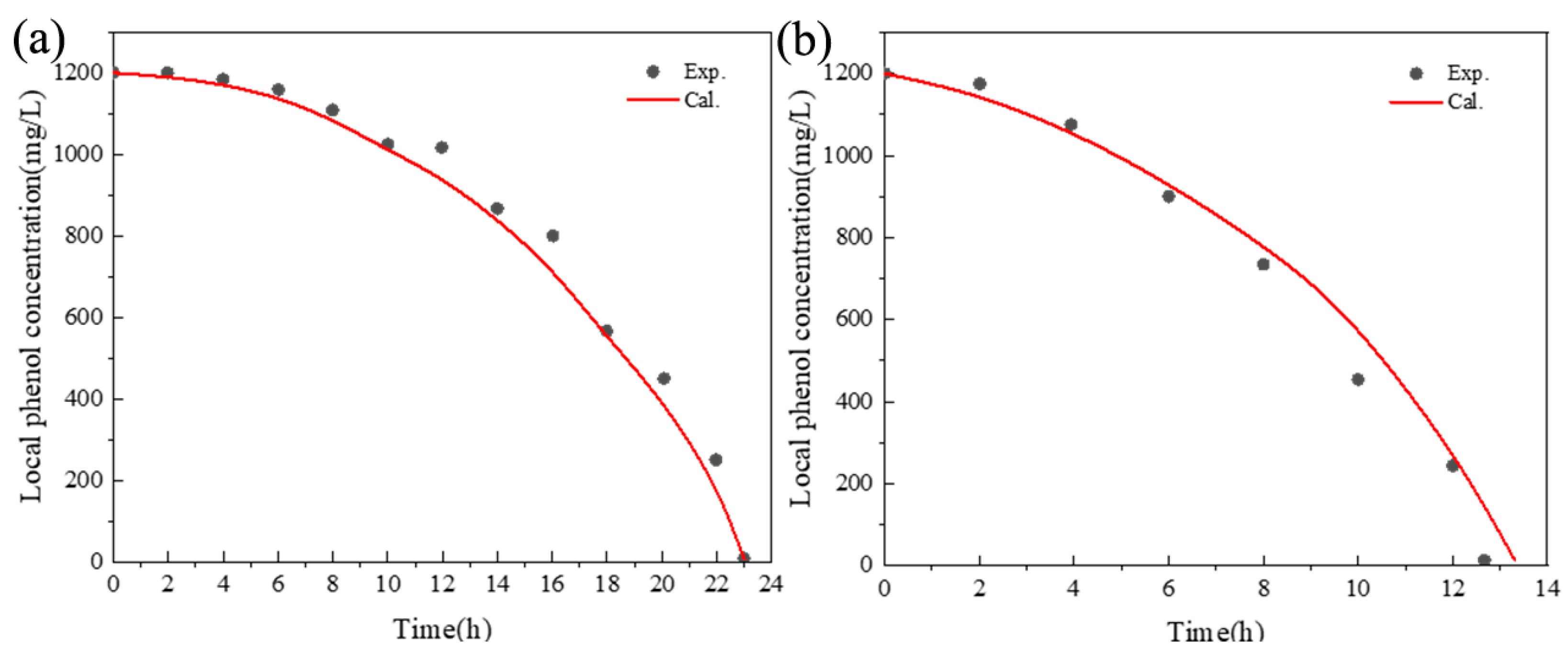
The simulated local cell concentrations and dissolved phenol concentrations under different initial cell concentrations are compared with the findings reported in the experimental study of Feng et al. [12]. Figure 7 and Figure 8 show a good agreement between them, indicating that the model proposed in this work is able to characterize the biodegradation of phenol in the ALR. As the initial cell concentration increases, substrate inhibition has a weaker effect on microbial growth, more cells would be generated by the nutrient substance in the liquid phase, and the biodegradation rate would increase. The dissolved phenol is biodegraded totally within 13 h at the initial cell concentration of 102 mg/L, which is about 10 h faster than that at the initial cell concentration of 34 mg/L.
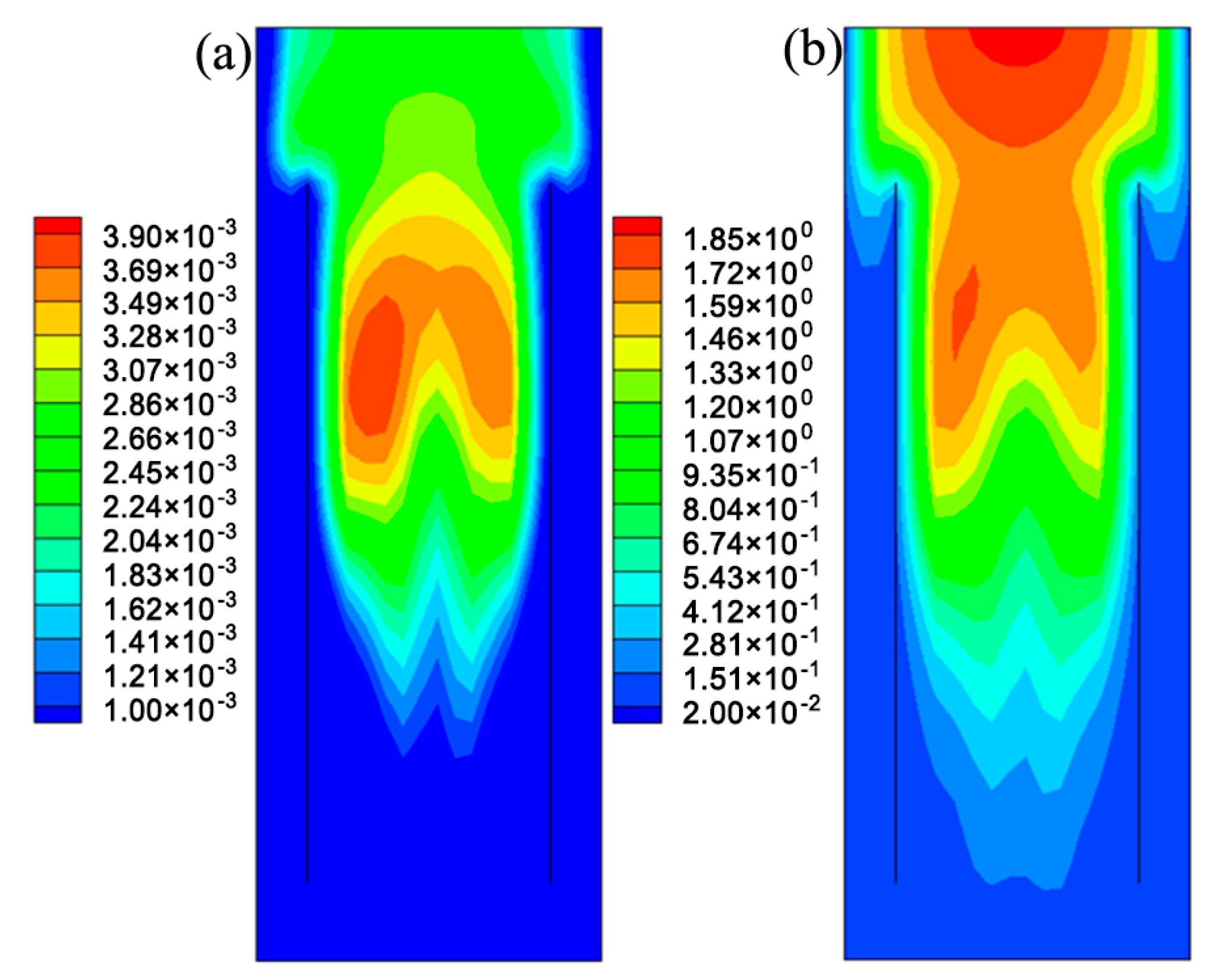
Figure 9a,b show the contours of Dt of dissolved phenol and liquid phase turbulent viscosity, respectively. Similar distribution patterns are observed for Dt and turbulent viscosity, and both Dt and turbulent viscosity increase with increasing ALR height. At a fixed ALR height, Dt decreases quickly in the near-wall region. This could be attributed to the constraint of turbulence in this region. In the previous works, Dt is often calculated by using Sct and assuming that Dt is proportional to the turbulent viscosity. Huang et al. adopted Sct = 0.75 to simulate the direct coal liquefaction process in an ALR [21], while Talvy et al. predicted the absorption process in an ALR by assuming Sct = 1 [38]. Figure 10 displays the profiles of calculated Sct at different heights, which shows that Sct varies throughout the ALR. So the traditional Sct method may not be feasible for the wastewater biodegradation process in the ALR. The c 2 ¯ -εc model proposed in this work is more rigorous, as it takes into account the impact of concentration fluctuation on the turbulent mass transfer.

5.2. Comparison between Different Structures of ALRs

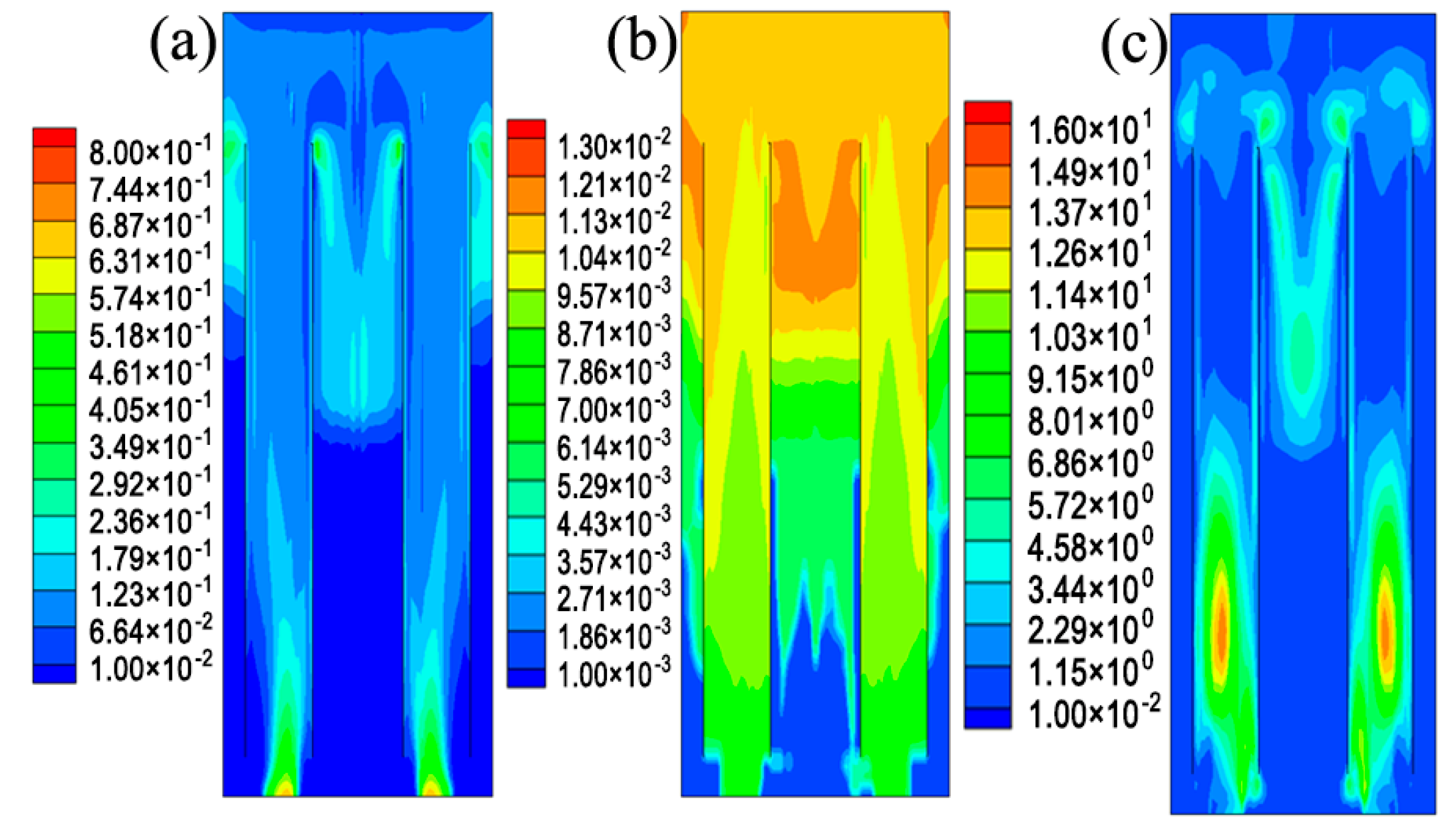
Figure 11 displays the contours of simulated distributions of the gas holdup, Sauter bubble size, and shear stress in the novel ALR when the superficial gas velocity is 0.02 m/s. By comparison, it is found that gas holdup is more uniformly distributed in the novel ALR. Additionally, Figure 11b reveals that bubble size increases with increasing ALR height and the largest bubble size appears in the upper part of the downcomer. Figure 11c shows the contour of shear stress distribution in the novel ALR. The largest shear stress appears in the lower part of the riser and the shear stress is rather small in other regions of the ALR, which are different from that in the original ALR. Table 1 compares volume-averaged gas holdup, bubble size, and shear stress between original and novel ALR. As shown, the novel ALR is characterized by smaller bubble size and higher gas holdup and thus it can provide more gas–liquid interfacial areas, which means greater mass transfer performance. Additionally, smaller volume-averaged shear stress is observed in the novel ALR, which is favorable for the biodegradation process.
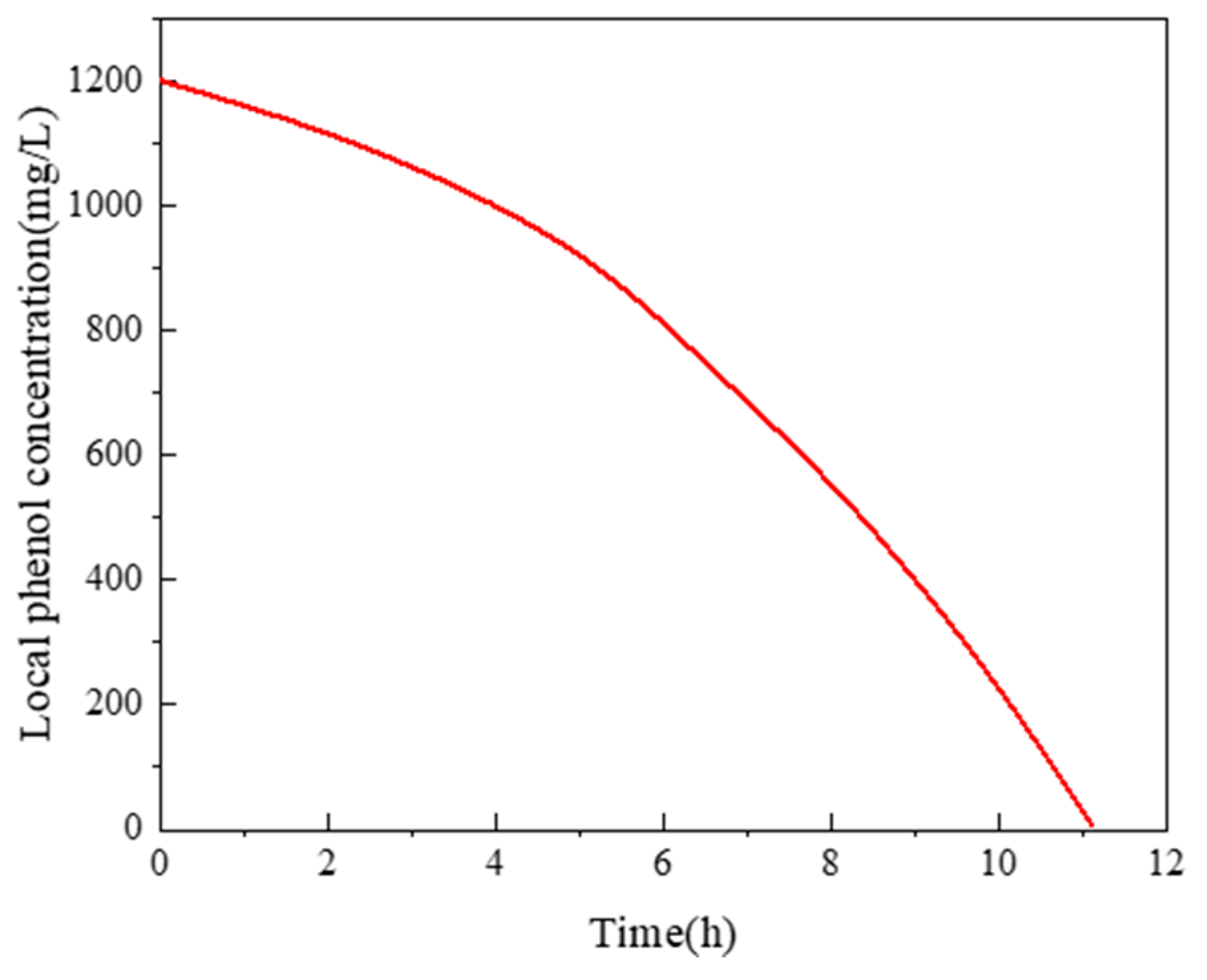
Figure 12 displays the variation in the concentration of dissolved phenol during the biodegradation in the novel ALR. A comparison of Figure 12 with Figure 8b reveals that dissolved phenol would be totally degraded within about 11 h and the biodegradation rate is greater in the novel ALR, which may be due to its excellent hydraulic performance.

6. Conclusions

This study proposes a 3D CFD model to characterize the dynamic biodegradation of phenol in the ALR. The turbulent effect is determined by the standard k-ε model and the bubble size distribution is predicted by the population balance model. The turbulent mass diffusivity Dt is decided by the c 2 ¯ -εc model, so the empirical methods for simulating the turbulent mass transfer process can be avoided. The simulation results agree well with the experimental data, indicating that the proposed model is able to characterize the biodegradation of phenol in the ALR. The predicted distributions of Dt and turbulent viscosity are not identical, which indicates that it may not be reasonable to assume a constant Sct in the ALR. Additionally, a novel structure of ALR is proposed and it has better hydraulic and biodegradation performance than the original one.

Author Contributions

Conceptualization, Simulation, Data collection, Draft preparation, L.L.; Resources, Validation, Visualization, Writing—review and editing, R.H.; Software, Writing—review and editing, X.J.; Validation, Investigation, Visualization, Writing—review and editing, Y.H.; Resources, Investigation, Writing—review and editing, C.F.; Simulated case, Data curation, Writing—original draft preparation, C.Z.; Writing—original draft preparation, X.G. All authors have read and agreed to the published version of the manuscript.

Funding

This research was funded by China National Offshore Oil Corporation (CNOOC, Grant No. CNOOC-KJ 145 FZDXM 00 TJY 003 TJY 2021).

Data Availability Statement

Not applicable.

Conflicts of Interest

The authors declare no conflict of interest.

References

  1. Wadaugsorn, K.; Limtrakul, S.; Vatanatham, T.; Ramachandran, P.A. Hydrodynamic behaviors and mixing characteristics in an internal loop airlift reactor based on cfd simulation. Chem. Eng. Res. Des. 2016, 113, 125–139. [Google Scholar] [CrossRef]
  2. Luo, H.-P.; Al-Dahhan, M.H. Local characteristics of hydrodynamics in draft tube airlift bioreactor. Chem. Eng. Sci. 2008, 63, 3057–3068. [Google Scholar] [CrossRef]
  3. Wang, X.; Jia, X.; Wen, J. Transient modeling of toluene waste gas biotreatment in a gas–liquid airlift loop reactor. Chem. Eng. J. 2010, 159, 1–10. [Google Scholar] [CrossRef]
  4. Ansoni, J.L.; Santiago, P.A.; Seleghim, P. Multiobjective optimization of a flat-panel airlift reactor designed by computational fluid dynamics. Chem. Eng. Sci. 2019, 195, 946–957. [Google Scholar] [CrossRef]
  5. Han, Y.; Zhang, L.; Liu, M.; Niu, J. Numerical simulation of the hydrodynamic behavior and the synchronistic oxidation and reduction in an internal circulation micro-electrolysis reactor. Chem. Eng. J. 2020, 381, 122709. [Google Scholar] [CrossRef]
  6. Feng, W.; Wen, J.; Jia, X.; Yuan, Q.; Sun, Y.; Liu, C. Modeling for local dynamic behaviors of phenol biodegradation in bubble columns. AIChE J. 2006, 52, 2864–2875. [Google Scholar] [CrossRef]
  7. Muñoz Sierra, J.D.; Oosterkamp, M.J.; Spanjers, H.; van Lier, J.B. Effects of large salinity fluctuations on an anaerobic membrane bioreactor treating phenolic wastewater. Chem. Eng. J. 2021, 417, 129263. [Google Scholar] [CrossRef]
  8. Kamali, M.; Aminabhavi, T.M.; Tarelho, L.A.C.; Hellemans, R.; Cuypers, J.; Capela, I.; Costa, M.E.V.; Dewil, R.; Appels, L. Acclimatized activated sludge for enhanced phenolic wastewater treatment using pinewood biochar. Chem. Eng. J. 2022, 427, 131708. [Google Scholar] [CrossRef]
  9. Patil, S.S.; Jena, H.M. Biodegradation of diethyl phthalate from synthetic wastewater in a batch operated internal loop airlift bioreactor. Int. Biodeterior. Biodegrad. 2019, 143, 104728. [Google Scholar] [CrossRef]
  10. Livingston, A.G. Biodegradation of 3,4-dichloroaniline in a fluidized bed bioreactor and a steady-state biofilm kinetic model. Biotechnol. Bioeng. 1991, 38, 260–272. [Google Scholar] [CrossRef] [PubMed]
  11. Gholami, F.; Zinatizadeh, A.A.; Zinadini, S.; McKay, T.; Sibali, L. An innovative jet loop-airlift bioreactor for simultaneous removal of carbon and nitrogen from soft drink industrial wastewater: Process performance and kinetic evaluation. Environ. Technol. Innov. 2020, 19, 100772. [Google Scholar] [CrossRef]
  12. Feng, W.; Wen, J.; Liu, C.; Yuan, Q.; Jia, X.; Sun, Y. Modeling of local dynamic behavior of phenol degradation in an internal loop airlift bioreactor by yeast candida tropicalis. Biotechnol. Bioeng. 2007, 97, 251–264. [Google Scholar] [CrossRef] [PubMed]
  13. Wen, J.P.; Chen, Y.; Jia, X.Q.; Mao, G.Z. Removal of toluene from air streams using a gas-liquid-solid three-phase airlift loop bioreactor containing immobilized cells. J. Chem. Technol. Biotechnol. 2006, 81, 17–22. [Google Scholar]
  14. Šimčík, M.; Mota, A.; Ruzicka, M.C.; Vicente, A.; Teixeira, J. Cfd simulation and experimental measurement of gas holdup and liquid interstitial velocity in internal loop airlift reactor. Chem. Eng. Sci. 2011, 66, 3268–3279. [Google Scholar] [CrossRef]
  15. Gandhi, A.B.; Gupta, P.P.; Joshi, J.B.; Jayaraman, V.K.; Kulkarni, B.D. Development of unified correlations for volumetric mass-transfer coefficient and effective interfacial area in bubble column reactors for various gas− liquid systems using support vector regression. Ind. Eng. Chem. Res. 2009, 48, 4216–4236. [Google Scholar] [CrossRef]
  16. Lu, X.; Ding, Y.; Yu, J.; Long, B.; Zheng, X. Experimental study of hydrodynamics and bubble size distribution of an external loop airlift reactor. Can. J. Chem. Eng. 2019, 97, 1685–1693. [Google Scholar] [CrossRef]
  17. Särkelä, R.; Eerikäinen, T.; Pitkänen, J.-P.; Bankar, S. Mixing efficiency studies in an airlift bioreactor with helical flow promoters for improved reactor performance. Chem. Eng. Process.—Process Intensif. 2019, 137, 80–86. [Google Scholar] [CrossRef]
  18. Young, M.A.; Carbonell, R.G.; Ollis, D.F. Airlift bioreactors: Analysis of local two-phase hydrodynamics. AIChE J. 1991, 37, 403–428. [Google Scholar] [CrossRef]
  19. Teli, S.M.; Mathpati, C.S. Experimental and numerical study of gas-liquid flow in a sectionalized external-loop airlift reactor. Chin. J. Chem. Eng. 2021, 32, 39–60. [Google Scholar] [CrossRef]
  20. Zhong, F.; Xing, Z.; Cao, R.; Liu, Y.; Ma, Y.; Shang, W.; Liang, M.; Mei, X. Flow regimes characteristics of industrial-scale center-rising airlift reactor. Chem. Eng. J. 2022, 430, 133067. [Google Scholar] [CrossRef]
  21. Huang, Q.; Zhang, W.; Yang, C. Modeling transport phenomena and reactions in a pilot slurry airlift loop reactor for direct coal liquefaction. Chem. Eng. Sci. 2015, 135, 441–451. [Google Scholar] [CrossRef]
  22. Kouzbour, S.; Stiriba, Y.; Gourich, B.; Vial, C. Cfd simulation and analysis of reactive flow for dissolved manganese removal from drinking water by aeration process using an airlift reactor. J. Water Process Eng. 2020, 36, 101352. [Google Scholar] [CrossRef]
  23. Mavaddat, P.; Mousavi, S.M.; Amini, E.; Azargoshasb, H.; Shojaosadati, S.A. Modeling and cfd-pbe simulation of an airlift bioreactor for phb production. Asia-Pac. J. Chem. Eng. 2014, 9, 562–573. [Google Scholar] [CrossRef]
  24. Sun, Z.; Liu, B.; Yuan, X.; Liu, C.; Yu, K. New turbulent model for computational mass transfer and its application to a commercial-scale distillation column. Ind. Eng. Chem. Res. 2005, 44, 4427–4434. [Google Scholar] [CrossRef]
  25. Li, W.B.; Liu, B.T.; Yu, K.T.; Yuan, X.G. Rigorous model for the simulation of gas adsorption and its verification. Ind. Eng. Chem. Res. 2011, 50, 8361–8370. [Google Scholar] [CrossRef]
  26. Li, W.; Yu, K.; Liu, B.; Yuan, X. Computational fluid dynamics simulation of hydrodynamics and chemical reaction in a cfb downer. Powder Technol. 2015, 269, 425–436. [Google Scholar] [CrossRef]
  27. Zhang, C.; Yuan, X.; Luo, Y.; Yu, G. Prediction of species concentration distribution using a rigorous turbulent mass diffusivity model for bubble column reactor simulation part ii: Analogy between turbulent mass and momentum transfer in toluene emissions biodegradation process. Chem. Eng. Sci. 2018, 189, 360–368. [Google Scholar] [CrossRef]
  28. Huang, Q.S.; Yang, C.; Yu, G.Z.; Mao, Z.S. 3-d simulations of an internal airlift loop reactor using a steady two-fluid model. Chem. Eng. Technol. 2007, 30, 870–879. [Google Scholar] [CrossRef]
  29. Schiller, L.A.; Naumann, Z. A drag coefficient correlation. Ver. Dtsch. Ing. 1935, 77, 318–320. [Google Scholar]
  30. Troshko, A.A.; Zdravistch, F. Cfd modeling of slurry bubble column reactors for fisher–tropsch synthesis. Chem. Eng. Sci. 2009, 64, 892–903. [Google Scholar] [CrossRef]
  31. Zhang, C.; Yuan, X.; Luo, Y.; Yu, G. Prediction of species concentration distribution using a rigorous turbulent mass diffusivity model for bubble column reactor simulation part i: Application to chemisorption process of CO2 into naoh solution. Chem. Eng. Sci. 2018, 184, 161–171. [Google Scholar] [CrossRef]
  32. Luo, H. Coalescence, Breakup and Liquid Circulation in Bubble Column Reactors. Ph.D. Thesis, University of Trondheim, Trondheim, Norway, 1993. [Google Scholar]
  33. Luo, H.; Svendsen, H.F. Theoretical model for drop and bubble breakup in turbulent dispersions. AIChE J. 1996, 42, 1225–1233. [Google Scholar] [CrossRef]
  34. Liu, G.B.; Yu, K.T.; Yuan, X.G.; Liu, C.J. New model for turbulent mass transfer and its application to the simulations of a pilot-scale randomly packed column for CO2−NaOH chemical absorption. Ind. Eng. Chem. Res. 2006, 45, 3220–3229. [Google Scholar] [CrossRef]
  35. Li, W.; Zhao, X.; Liu, B.; Tang, Z. Mass transfer coefficients for co2 absorption into aqueous ammonia using structured packing. Ind. Eng. Chem. Res. 2014, 53, 6185–6196. [Google Scholar] [CrossRef]
  36. Jia, X.; Wen, J.; Zhou, H.; Feng, W.; Yuan, Q. Local hydrodynamics modeling of a gas–liquid–solid three-phase bubble column. AIChE J. 2007, 53, 2221–2231. [Google Scholar] [CrossRef]
  37. Sinha, J.; Bae, J.T.; Park, J.P.; Kim, K.H.; Song, C.H.; Yun, J.W. Changes in morphology of paecilomyces japonica and their effect on broth rheology during production of exo-biopolymers. Appl. Microbiol. Biotechnol. 2001, 56, 88–92. [Google Scholar] [CrossRef]
  38. Talvy, S.; Cockx, A.; Liné, A. Modeling of oxygen mass transfer in a gas–liquid airlift reactor. AIChE J. 2007, 53, 316–326. [Google Scholar] [CrossRef]
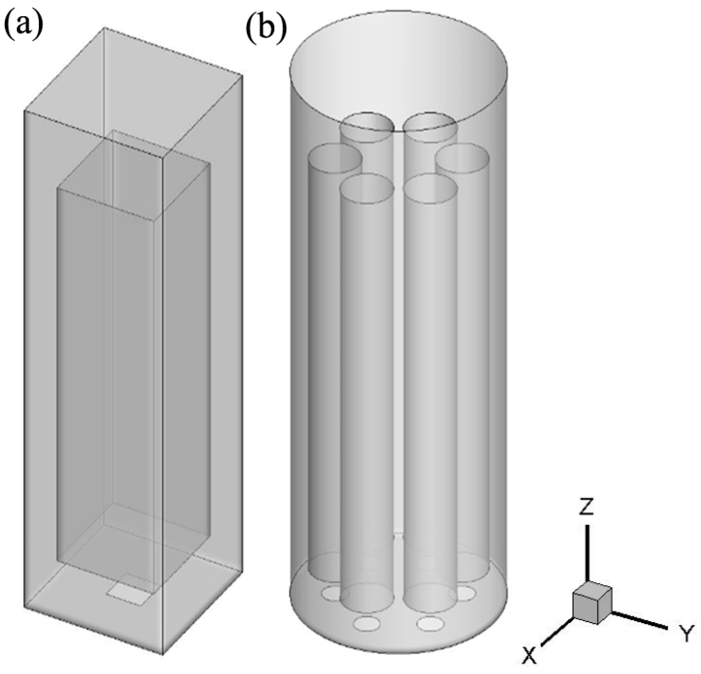
Figure 1. A schematic of the simulated ALRs: (a) rectangle ALR; (b) cylinder ALR with six cylindrical draft tubes.
Processes 11 00484 g001
Figure 2. Schematic view of the grids: (a) rectangle ALR; (b) cylinder ALR with six cylindrical draft tubes.
Processes 11 00484 g002
Figure 3. The profiles of (a) gas holdup and (b) liquid axial velocity in the XZ−plane at Y = 0.1 m in the ALR when the superficial gas velocity is 0.02 m/s.
Processes 11 00484 g003
Figure 4. The contours of gas holdup obtained at different superficial gas velocities in the XZ−plane at Y = 0.1 m in the ALR: (a) ug = 0.01 m/s, (b) ug = 0.02 m/s.
Processes 11 00484 g004
Figure 5. The contours of the Sauter bubble size distribution (m) in the XZ−plane at Y = 0.1 m in the ALR at ug = 0.02 m/s.
Processes 11 00484 g005
Figure 6. Distributions of shear stress (kg m−1s−2) in the XZ−plane at Y = 0.1 m in the ALR at (a) ug = 0.01 m/s and (b) ug = 0.02 m/s.
Processes 11 00484 g006
Figure 7. Comparison between simulated cell concentrations and experimental results: (a) initial cell concentration: 34 mg/L; (b) initial cell concentration: 102 mg/L.
Processes 11 00484 g007
Figure 8. Comparison between simulated dissolved phenol concentrations and experimental results: (a) initial cell concentration: 34 mg/L; (b) initial cell concentration: 102 mg/L.
Processes 11 00484 g008
Figure 9. The contour of (a) turbulent mass diffusivity of dissolved phenol (m2/s) and (b) turbulent viscosity (kg/(m·s)) in the XZ−plane at Y = 0.1 m in the ALR.
Processes 11 00484 g009
Figure 10. Profiles of Sct in the XZ−plane at Y = 0.1 m at different ALR heights.
Processes 11 00484 g010
Figure 11. The contour of the (a) gas holdup, (b) Sauter bubble size distribution (m), and (c) shear stress in the XZ−plane at Y = 0.12 m in the novel ALR at ug = 0.02 m/s.
Processes 11 00484 g011
Figure 12. The variation of dissolved phenol concentration at an initial cell concentration of 102 mg/L.
Processes 11 00484 g012
Table 1. Comparison of bubble size, volume-averaged gas holdup, and shear stress between original and novel ALR.
Type of ALRVolume-Averaged Gas HoldupVolume-Averaged Sauter Bubble Size (m)Volume-Averaged
Shear Stress (kg·m−1s−2)
original0.0530.00923.798
novel0.0730.00791.370
Disclaimer/Publisher’s Note: The statements, opinions and data contained in all publications are solely those of the individual author(s) and contributor(s) and not of MDPI and/or the editor(s). MDPI and/or the editor(s) disclaim responsibility for any injury to people or property resulting from any ideas, methods, instructions or products referred to in the content.