1. Introduction
In the field of product design and education, obviously, color 3D printing will be required for more applications, and special care must be taken when positioning the print head mechanism [
1]. Presently, powder binder and multi-jet technology are relatively mature 3D color printing technologies [
2]. These resin color models are brightly colored and exhibit sufficient color expression; however, the high cost of equipment and raw materials hinder their application in many fields. Thus, FDM technology holds considerable potential for the development of color printing technology due to its low cost and convenient operation [
3].
As is well known, the printing mode of FDM has always been used in monochromatic, two-color, or three-color printing [
4]. There are now a number of manufacturers that produce such 3D printers. The models produce the appearance of multiple or progressive colors. Many researchers have made attempts to create FDM3D color printing. For example, Eammon Littler proposed a coloring method for pigmenting white PLA by using alcohol-based inks prior to extrusion, in which the color was added to the surface on white models with a attached ink tank [
5].
Hergel Jean and Lefebvre Sylvain realize FDM multiple-color printing through changing different proportions of the three primary colors squeezed into one nozzle. The employed printer contains several extruders. Each nozzle extrudes a color of filament The different parts of the model can be printed in different colors [
6]. However, the model still lacks sufficient colors. In general, the present technology for color FDM printers lacks sufficient color expression due to low color resolution.
Mariya et al. compares the color stability of 3D printed and acrylic material denture-based resin, which demonstrates that 3D printed denture-based resin has more promising color stability [
7]. Kim et al. factor in the biocompatibility effect on 3D color printed resin for use in medical devices [
8]. Ioan et al. conducted an experimental study on the effect of various FDM color printing parameters in relation to the tensile strength and surface quality of the resulting printed material, which concluded that the most influential parameter is infill density [
9]. Wang et al. propose a novel color strategy for 3D printing based on a single-channel nozzle through regulating the pH of the extruded line [
10]. However, the 3-D printing strategy has not been implemented to print a complex geometry.
The aim of this paper is to use the Carreau model to simulate the motion process of pseudoplastic fluids in FDM 3D printing in the forced mixing state based on the non-Newtonian fluid theory. For molten PLA materials, which are non-Newtonian fluids with a high viscosity, Carreau laminar flow models were used in the analysis to model the plastic fluid and derive the corresponding viscosity change formula. The MIX model is used to simulate the mixing process of a two-fluid model under active agitation.
This paper proposes three conceptual color mixing mechanisms based on the aforementioned theories: a triangular mixing shaft, a rectangular spoiler stirring shaft, and a spiral blade string shaft.
The mixing process is modeled using the non-Newtonian fluid theory, with the Carreau model used to simulate the motion of a pseudoplastic fluid in FDM 3D printing under forced mixing. Four conceptual stirring shaft structures with different morphologies were designed from the three conceptual color mixing mechanisms, phase line diagrams for non-Newtonian fluid mixing were calculated, and mixing ratios were compared. For further optimization, a conceptual structure with good mixing results was chosen, and a combined design of a rectangular spoiler stirring shaft and a spiral blade tandem shaft was chosen. The proportions of the different mixing colors and the velocity field in the mixing chamber were investigated by analyzing the mixing and stirring process with the improved stirring shaft. Finally, a printing nozzle with five inlets and one squeeze outlet was designed and built for experimental analysis, and a color model was printed to demonstrate the correctness of the simulation and the rationality of the integrated design of the rectangular spoiler stirring shaft and a spiral blade string shaft.
In this paper, four different conceptual stirring shaft structures are designed, the phase line diagrams of non-Newtonian fluid mixing are calculated, and the mixing ratio is compared; then, a conceptual structure with good mixing effect is selected for further optimization and design, and a spiral feeding structure with a staggered spoiler rod arrangement is designed. By analyzing the mixing and stirring process of the modified stirring shaft, the proportion of different mixing colors and the velocity field in the mixing chamber are analyzed. Finally, the printing nozzles with five inlets and one extrusion port are designed and produced, a color 3D experimental printing system is built for experimental analysis, and the color model is printed, proving the correctness of the simulation and the rationality of the stirring shaft structure.
2. Material and Methods
2.1. CFD (Non-Newtonian Flow)
In order to study the influence of different stirring shaft structures on the mixing effect, we first designed different stirring structures with Solidworks, and then imported the stp file of the stirring model into the software Ansys. After pre-processing, we used Gambit to mesh the stirring shaft. After setting the boundary conditions, Fluent was used for simulation calculation.
2.2. Experimental Setup
The material used in the simulation and experiment is polylactic acid (PLA) material. Polylactic acid (PLA) is a new type of biodegradable material with superior tensile strength and extensibility which can be used in the production of various plastics. The glass transition temperature of PLA is about 60 °C, and the melting temperature is about 170 °C. PLA is also a common printing material.
The physical 3-D printer used was the DELTA3D printer, with a parallel mechanism. One of the advantages of this machine is the high stiffness of the printing head mounts, which can support the large weight of the printing nozzles. Another advantage of the machine is that the mounting space of the machine is sufficient to accommodate multiple wire feeding mechanisms so that printing experiments can be conducted using a variety of different colors of materials. The detail of the machine and the experimental method are described in
Section 7.
3. Mathematical Representation of Models
3.1. Non-Newtonian Fluid Dynamics Model
To simplify the analysis process, in the following simulation, only two colored filaments are discussed under the conditions of two feed hoses and one extrusion nozzle.
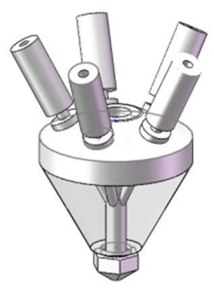
The agitation mixing movement is carried out by the rotation of the agitator shaft, which is driven by an external micro-motor. The molten state of viscous material is extruded from the printing nozzle (See
Figure 1) to form the model. The non-Newtonian fluid in the stirring cavity flows into the cavity, driven by the two elements: the motion of stirring shaft and gravity. The flow behaviors are modeled based on the laws of mass conservation, momentum conservation, and energy conservation [
11].
The law of conservation of mass is:
where
is density,
is time, and
is the component of the velocity vector in the direction of
x,
y, and
z respectively.
The laws of conservation of momentum are:
where
is dynamic viscosity,
is the pressure on the element, and
,
,
is the generalized source term in the momentum conservation equation.
Correspondingly, , , .
The expression of
is:
In general is the component of the volume force in the x, y, z direction.
Considering the fact that the molten PLA material can be regarded as non-Newtonian fluid, the viscosity of the fluid is defined as:
where
H(
T) is the temperature dependence, known as the Arrhenius law.
where
is the ratio of the activation energy to the thermodynamic constant and
is a reference temperature for which . , which is the temperature shift, is set to 0 by default and corresponds to the lowest thermodynamically acceptable temperature. and are input parameters. is a measure of the average viscosity of the fluid (the consistency index), and is a measure of the deviation of the fluid from Newtonian (the power-law index). The value of determines the class of the fluid:
= 1→Newtionian fluid
> 1→shear thickening (dilatant fluids)
< 1→shear thinning (pseudo-plastics)
For molten PLA fluids, the viscosity of fluids decreases with the increase in shear stress or shear rate, which is characteristic of pseudoplastic fluids. According to the description of the power law model, shown in Equation (5), the viscosity of the fluid varies with the shear rate, when when . Here and are the upper and lower limits of fluid viscosity, respectively.
The Carreau model for pseudoplastic fluids attempts to establish a curve that combines the shear laws of Newtonian and non-Newtonian fluids to describe a wide range of fluids. In the Carreau model, the viscosity is [
12,
13]:
The parameters
and
are dependent on the fluid.
is a time constant,
is the power-law index (non-Newtonian power law),
and
are, respectively, zero-shear viscosity and infinite shear viscosity.
is a reference temperature, and
is the ratio of the activation energy to thermodynamic constant.
is the temperature dependence, known as the Arrhenius law [
13]. The variation of viscosity with shear rate is in accordance with the Carreau model.
3.2. Multiple Reference Frame Model
The main stirring model is the multiple reference frame (MRF) model. The MRF model is a steady-state approximation in which different computational regions can be assigned to different rotational speeds. The flow in each region can be solved by the moving reference frame equation. For coordinate systems that rotate stably at angular velocity in the inertial frame, the transition from the stationary system to the rotating system can be transformed by following Equation [
13]:
where
is the relative velocity,
is the absolute velocity,
is the angular velocity, and
is the position vector.
At the interface of two cells (the interface), the local reference frame is transformed so that the flow variables in one region can be used to calculate the flux in the adjacent region. The MRF model does not take into account the relative motion between meshes. That means that the mesh is in a relatively static state, which freezes the motion of the moving parts in a specific position, enabling the calculation of the instantaneous motion of the rotor in this position. For this reason, MRF is often referred to as the “frozen rotor method” [
14,
15]. The MRF model used in this paper is shown in
Figure 2. The whole computational region is divided into a steady zone and a moving zone [
16]. The moving zone is used as the zone of active stirring, in which the motion coordinate system is adopted. The steady zone uses the stationary coordinate system. The two regions are converted into reference frames through the interface.
3.3. Establishment of Simulation Model
The cross-section based on the MFR model is shown in
Figure 2.
Figure 2 is divided into a steady-state region of the outer layer and a moving region of the inner layer. The cross in the middle of the inner layer is an abstract mixer cross section. Before analyzing, the design of the stirring shaft must be completed, and the black box processing method is adopted in Design Modeler (D. Smith et al., 2010) [
17]. Through a Boolean subtraction operation, the imaginary velocity field around the stirring shaft is regarded as the source of fluid momentum, and the stirring shaft is processed. Then, by stretching slice, the stirring cavity is divided into an internal rotating zone (moving zone) and an external static zone (steady zone), and the simulation model is established.
4. Mesh Generations
At the meshing step, the steady zone is divided into sweep meshes, and the moving zone is divided into tetrahedral meshes. The encryption settings for specific areas are then completed, and the meshes are generated. The simulation model for the single-phase two-fluid mixture is basically the same as the model for single-fluid simulation. As mentioned previously, a filament mixing zone with only 2 inlets and 1 extrusion nozzle, which means a simplified stirring cavity, is used as the simulation model; thus, there are two fluids defined as inflow. Considering the factor of atmosphere, the position of the nozzle is set as a free outlet. Pressure and gravity commonly act on the flow of the fluid after it enters, and the rest of the system remains unchanged. The mesh model and boundary names are shown in
Figure 3.
5. Parameter Settings of the Simulation
When applying the MIXTURE, Carreau, and MRF models in Fluent, the specific operation is as follows in
Table 1. The melting temperature of PLA material was set at 210 °C during the simulation
The selection of flow is related to the characteristics of fluids and the printing process. The Reynolds number of melted PLA fluid can be calculated by
Where, D is the blade diameter of the stirring shaft, u is the blade speed, ρ is density, and μ is the dynamic viscosity. The diameter of the simulated stirring shaft is 5 mm, and the rotational speed is 90 r/min. The average hydrodynamic viscosity obtained by simulation is 400, and the Reynolds number obtained by calculation is approximately 117.2. In general, these fluid results can be treated as laminar flow.
6. Structural Optimization Simulation of Stirring Shaft
Without loss of generality, we first preliminarily conceptualized three color mixing axes: a triangular mixing shaft, a rectangular spoiler stirring shaft, and a spiral blade string shaft.
The mixing process is modeled using non-Newtonian fluid theory, with the Carreau model used to simulate the motion of a pseudoplastic fluid in FDM 3D printing under forced mixing. Four conceptual stirring shaft structures with different morphologies were designed from the three conceptual color mixing mechanisms; phase line diagrams for non-Newtonian fluid mixing were calculated, and mixing ratios were compared. For further optimization, a conceptual structure with good mixing results was chosen, and a combined design of a rectangular spoiler stirring shaft and a spiral blade tandem shaft was chosen. The proportions of the different mixing colors and the velocity field in the mixing chamber were investigated by analyzing the mixing and stirring process with the improved stirring shaft. Finally, a printing nozzle with five inlets and one squeeze outlet was designed and built for experimental analysis, and a color model was printed to demonstrate the correctness of the simulation and the rationality of the integrated design of the rectangular spoiler stirring shaft, and the spiral blade string shaft.
In order to obtain the optimized geometry of the stirring shafts, four different stirring shafts designed in different structures are simulated for comparative analysis. The structure of the first type of stirring shaft is shown in
Figure 4a.
As shown in
Figure 4a, the preliminarily selected agitation axis is a triangular prism with an equilateral triangle at the bottom. In the following simulation process, Fluent is used to analyze the mixing of the red and blue PLA materials. The shaft rotational speed is specified as 90 rpm, which is an acceptable stirring speed for a duration of 1 s for the mixing process.
Figure 4b shows the phase distribution corresponding to the exit section of the mixing cavity.
It can be seen from the results of the cloud image that the original red and blue areas still occupy most of the area, while the remaining area, except the red and blue areas, is the area where color mixing occurs. The larger the area, the better the mixing. In order to quantitativelymeasure the size of the mixing region, the percentage of the pixel number of the mixing region and the pixel number of the whole image is calculated by the Matlab image processing method.
Step 1: Use the ‘imread’ function to read the image, use the ‘size’ function to obtain the image size and the total number of pixels, P; Step 2: Use the ‘imhist’ function to count the number of unmixed blue and red pixels, P1 and P2; Step 3: Calculate the color mixing ratio value, R = (P1 + P2)/P*100%. The calculated result is 24.8%, which means that the mixing state is not good. This shows that the mixing axis of the triangular prism is not conducive to the mixing effect.
In order to improve the mixing effect, the triangular prism structure is further improved with a number of separate spoiler structures, as shown in
Figure 5a. The spoiler is a short rod with a rectangular cross section, connected to the stirring shaft cylinder at a vertical angle, and each spoiler is separated by 90° in the circumferential direction. The upper and lower surfaces of the spoiler will increase the friction with the fluid. At the same time, the spacing between the different spoiler rods will cause the fluid to decrease the circumferential velocity. This low-speed fluid has a velocity difference in regards to the higher-speed fluid pushed along the circumference by the spoiler rod, which is the main factor for mixing. Fluent analysis of this structure was carried out to obtain the phase distribution cloud map corresponding to the exit section of the mixing chamber (shown as
Figure 5b). The mixing area occupies 39.3%, which is better than the mixing effect of the first stirring shaft.
Although the structure of the second stirring shaft has a good mixing effect, due to the large viscosity of the viscous fluid, its downward flow speed is very slow under the action of gravity only, so it is necessary to increase the downward pushing power. For this purpose, the second step is to further improve the stirring shaft for the similar structure of the spiral vane, but the structure must consist of a continuous spiral blade, originally in a 90° segmentation, and an independent blade with an inscribed 90° angle between the adjacent blades, as shown in
Figure 6a, and its corresponding stirring shaft structure, as shown in
Figure 6b. CFD analysis of this structure, with a hybrid cavity exit section corresponding to the phase distribution of the cloud image (
Figure 6c), shows that the hybrid area occupies 35.6%, which is better than the results for the first type of mixed effect of a stirring shaft, the main reason being that the spiral blade vertical surface of viscous fluid produces greater friction resistance, reducing the speed of the increasing fluid; thus, the mixing effect is slightly smaller than that for the second stirring shaft. This is mainly due to fact that the fluid circumferential directional role of the spiral blade cross-section is small, producing fast flow under a small fluid volume, so when the partially mixed fluid is very small, to increase the blending ratio, the thickness of the spiral blade must also be increased, resulting in a greater drive in the circular movement of the fluid, providing a better mixture.
7. Optimization of Stirring Shaft
From the above analysis, it can be seen that the stirring shaft with the spoiler structure will produce a better mixing effect due to its relatively large cross section. However, such a stirring shaft does not generate sufficient propulsion force, and the viscosity of the non-Newtonian fluid can cause a pressure increase in the inner cavity that leads to the countercurrent phenomenon. Therefore, it is necessary to add a propulsion blade structure to the spoiler. The improved stirring shaft integrates the structures of the second and third types of stirring shafts, i.e., it is composed of a spoiler rod and propulsion blade, and the spoiler rod and spiral blade are arranged alternately in a staggered manner, as shown in
Figure 7. The section of the spoiler rod is changed from a rectangle to circle, which can reduce the resistance and the work demand of the driving motor. CFD analysis was carried out on the mixing process of the improved stirring shaft, and the analysis results are shown in
Figure 8. It can be seen from
Figure 8a that the mixing ratio of the two colors of the materials increased gradually from top to bottom. The phase diagram of different sections and the velocity distribution of the rotation domain of the improved stirring shaft were simulated and analyzed. As can be seen from
Figure 8b, the mixing effect of materials in the downward direction of the stirring shaft increases. As can be seen from the phase diagram at the bottom of the lower mixing chamber, the mixing area reaches 87%, which is much higher than the mixing effect of the first three types of stirring shafts. However, there is still a 13% unmixed area, and this unmixed area is mainly distributed in the outermost area because the outermost fluid of the material is affected by the viscous force of the inner wall of the mixing chamber and its approximate static, so it is difficult to form a mixture, but this does not hinder the color effect of the main mixing area.
In order to quantitatively reflect the influence of the stirring structure on the mixing process, as obtained from the data, the velocity field of the mixing cavity was analyzed.
Figure 9 shows the axial (Y coordinate direction) velocity distribution of a certain rotation domain wall surface from the rotation axis distance r (near the outer wall). It can be seen that there is a certain regular connection between the speed of the material and the agitator in both the longitudinal and circumferential directions. In order to better analyze the change in velocity on the wall surface of this rotational domain, the velocity value on the wall is intercepted along the axis of rotation at 60° intervals. As shown in
Figure 10, the abscissa is the height of the axis of rotation (from the entrance to the exit), and the ordinate is the velocity value at an angle on this wall. The common quantity takes the value of the 6 angular directions on the wall. As can be seen from the curve chart, the speed range along the axial direction in the initial position of the 6 angles is basically 0.04~0.07 m/s; as the material enters the mixing area, the speed along the axial direction gradually decreases, and stabilizes between 0~0.06 m/s. In this area, the speed fluctuation is basically consistent with the rotation of the stirring axis. However, when the material drops quickly away from the mixing area, the stirring effect along the tangential direction of the mixing shaft decreases, and the speed of the material along the axial direction gradually increases; when approaching the outlet interface position, the speed is basically within 0.04~0.09 m/s. From the cross-sectional view at the outlet (
Figure 11), it can be seen that the speed of the area close to the center of the nozzle reaches its maximum. This shows that this improved mixing shaft structure takes into account the combined role of the stirring action and the efficient extrusion of materials.
8. Experimental Analysis
In order to verify the correctness of the above simulation, this paper produced a stirring shaft with a spoiler rod and a mixing chamber, formed a color printing nozzle, and built a multi-filament feed 3D printing experimental device, which used 5 wire feeders to send 5 different colors of PLA consumables for mixed color printing. The colors of these 5 kinds of PLA are black, white, red, yellow, and blue. The combination between them can be mixed to produce any color.
Figure 12 shows a diagram of the print nozzle and its mounting position.
Figure 13 shows a color printed device diagram that uses a 3-axis parallel mechanism to control the movement position of the print head.
Figure 14 shows a long piece of wire printed by a color mixing experiment with a diameter of 0.4 mm. By adjusting the combination of different color materials and different feed rates, the extruded filaments can present a variety of different colors.
Figure 15 shows two printed models of a color sample in the form of several vases whose outer surfaces are polished and painted to make them more aesthetically pleasing. Both vases show different color variations, and in order to achieve even mixing, different color segments are printed at different regions. In
Figure 15a, a collection of printed dark colors is shown, where the color distribution is in harmony. As an example, a local region of dark green color further illustrates that the color is evenly distributed throughout the printed path. In
Figure 15b, a collection of light colors is selected, which demonstrates that the variation of color is in harmony here as well. The local region of light yellow further illustrates the color purity, as there is no bleed of color within the region. These resulting printed colors (see
Figure 15a,b) verify that the simulation result of an 87% total mixing area, as mentioned in
Section 7, is visually acceptable.
9. Conclusions
Based on the non-Newtonian fluid theory, this paper analyzes the pseudoplastic fluid flow behavior of FDM 3D printing under forced mixing. By establishing a plastic fluid model, the corresponding viscosity change formula is derived. Simulation results show that it is effective to analyze the PLA material mixing process using the Carreau model. In this paper, the effectiveness of different mixing shaft designs is compared, from which the spiral feed design, with a staggered spoiler arrangement, is the most promising. Finally, a hybrid printing nozzle was produced, and a color printing experimental device was built to conduct color mixing experiments. The experiments show that the stirring structure designed in this paper can produce a good color mixing effect and can print out a color model. The practical color printing results also verify that the 87% total mixing area calculated from CFD produces visually acceptable results.
Author Contributions
Conceptualization, methodology, validation, formal analysis, resources, and writing—original draft preparation, X.G.; software, investigation, and data curation, Z.W.; investigation and resources, Z.X.; establishment of the overall structure of the paper, P.L.C.; support regarding fundamental knowledge of CFD, M.H.Y. All authors have read and agreed to the published version of the manuscript.
Funding
Funding was provided by the Education Department of Jilin Province (Project Number: JJKH20220046KJ, January 2022, China).
Data Availability Statement
The data that support the findings of this study are available from the corresponding author upon reasonable request.
Conflicts of Interest
The authors declare no conflict of interest.
References
- Idà, E.; Nanetti, F.; Mottola, G. An Alternative Parallel Mechanism for Horizontal Positioning of a Nozzle in an FDM 3D Printer. Machines 2022, 10, 542. [Google Scholar] [CrossRef]
- Dimitrova, M.; Chuchulska, B.; Zlatev, S.; Kazakova, R. Colour Stability of 3D-Printed and Prefabricated Denture Teeth after Immersion in Different Colouring Agents—An In Vitro Study. Polymers 2022, 14, 3125. [Google Scholar] [CrossRef] [PubMed]
- Atwah, A.A.; Almutairi, M.D.; He, F.; Khan, M.A. Influence of Printing Parameters on Self-Cleaning Properties of 3D Printed Polymeric Fabrics. Polymers 2022, 14, 3128. [Google Scholar] [CrossRef] [PubMed]
- Spahiu, T.; Zlatev, Z.; Ibrahimaj, E.; Ilieva, J.; Shehi, E. Drape of Composite Structures Made of Textile and 3D Printed Geometries. Machines 2022, 10, 587. [Google Scholar] [CrossRef]
- Littler, E.; Zhu, B.; Jarosz, W. Automated filament inking for multi-color FFF 3D printing. In Proceedings of the 35th Annual ACM Symposium on User Interface Software and Technology, New York, NY, USA, 29 October–2 November 2022. [Google Scholar] [CrossRef]
- Hergel, J.; Lefebvre, S. Clean color: Improving multi-filament 3D prints. Comput. Graph. Forum 2014, 33, 469–478. [Google Scholar] [CrossRef]
- Dimitrova, M.; Capodiferro, S.; Vlahova, A.; Kazakova, R.; Kazakov, S.; Barile, G.; Corsalini, M. Spectrophotometric Analysis of 3D Printed and Conventional Denture Base Resin after Immersion in Different Colouring Agents—An In Vitro Study. Appl. Sci. 2022, 12, 12560. [Google Scholar] [CrossRef]
- Kim, G.T.; Go, H.B.; Yu, J.H.; Yang, S.Y.; Kim, K.M.; Choi, S.H.; Kwon, J.S. Cytotoxicity, Colour Stability and Dimensional Accuracy of 3D Printing Resin with Three Different Photoinitiators. Polymers 2022, 14, 979. [Google Scholar] [CrossRef] [PubMed]
- Tamașag, I.; Suciu, C.; Beșliu-Băncescu, I.; Dulucheanu, C.; Cerlincă, D.A. Experimental Study on the Possibilities of FDM Direct Colour Printing and Its Implications on Mechanical Properties and Surface Quality of the Resulting Parts. Polymers 2022, 14, 5173. [Google Scholar] [CrossRef] [PubMed]
- Wang, R.; Li, Z.; Shi, J.; Holmes, M.; Wang, X.; Zhang, J.; Zou, X. Color 3D printing of pulped yam utilizing a natural pH sensitive pigment. Addit. Manuf. 2021, 46, 102062. [Google Scholar] [CrossRef]
- Chhabra, R.P.; Richardson, J.F. Non-Newtonian Flow and Applied Rheology. In Non-Newtonian Flow and Applied Rheology, 2nd ed.; Elsevier Science: Oxford, UK, 2013. [Google Scholar]
- Hayat, T.; Aslam, N.; Khan, M.I.; Alsaedi, A. Physical significance of heat generation/absorption and Soret effects on peristalsis flow of pseudoplastic fluid in an inclined channel. J. Mol. Liq. 2018, 275, 599–615. [Google Scholar] [CrossRef]
- ANSYS_Flunet User’s Guide (Relasese 15.0); ANSYS, INC.: Washington County, PA, USA, 2014; pp. 424–431.
- Saha, G.K.; Maruf, M.H.I.; Hasan, M.R. Marine Propeller Modeling and Performance Analysis Using CFD Tools. In Proceedings of the AIP Conference Proceedings, Leuven, Belgium, 8–10 April 2019; Volume 2121, pp. 040012-1–040012-10. [Google Scholar]
- Brucato, A.; Ciofalo, M.; Grisafi, F.; Tocco, R. On the Simulation of Stirred Tank Reactors Via Computational Fluid Dynamics. Chem. Eng. Sci. 2000, 55, 291–302. [Google Scholar] [CrossRef]
- Kun, H. Ansys Icem CFD Project Example Explanation; People’s Posts and Telecommunications Publishing House: Beijing, China, 2014. [Google Scholar]
- Kawaguchi, J.Y. The characteristic research of Surfactant drag reduction solution in the free rotating flow. Xi’an Jiaotong Univ. J. 2006, 40, 315–318. [Google Scholar]
- Smith, D.E.; Wang, Q. Optimization-based design of polymer sheeting dies using generalized Newtonian fluid models. Polym. Eng. Sci. 2010, 45, 953–965. [Google Scholar] [CrossRef]
| Disclaimer/Publisher’s Note: The statements, opinions and data contained in all publications are solely those of the individual author(s) and contributor(s) and not of MDPI and/or the editor(s). MDPI and/or the editor(s) disclaim responsibility for any injury to people or property resulting from any ideas, methods, instructions or products referred to in the content. |
© 2023 by the authors. Licensee MDPI, Basel, Switzerland. This article is an open access article distributed under the terms and conditions of the Creative Commons Attribution (CC BY) license (https://creativecommons.org/licenses/by/4.0/).


