Abstract
The production of fused magnesia is a process in which raw materials are melted and recrystallized in the electric-fused magnesia furnace (EFMF). Temperature is the key factor that affects production, but it is difficult to be observed and monitored due to the high internal temperature. Thus, the working current is the standard for workers to judge whether the production process is normal. In order to master heat transfer characteristics in the furnace and accurately control the processes, a three-dimensional mathematical model of coupling the magnetic–fluid–thermal multifield has been established in a six-electrode EFMF. The model also considers the thermal decomposition of magnesium carbonate in the furnace. The phase change of materials is simulated by the solidification and melting model. The results show that the current density and Joule heat are concentrated in the region below the electrode. When the current size increases to 12,500 A, the molten pool begins to be connected. The average wall temperature at the end of the smelting stage is only 317.54 K, which conforms to the reality. The results of this study could provide guidance for practical production.
1. Introduction
As a high-quality refractory, fused magnesia is widely used in the electronic field [1], material field [2], metallurgy field [3], and so on. The performance of fused magnesia is closely related to the purity of magnesia, and the quality is usually measured by the mass fraction of magnesia. China is rich in magnesium ore, where magnesite reserves are the largest, and is a major producer of fused magnesia, playing a decisive role in the industry [4,5]. Fused magnesia is produced in the electric-fused magnesia furnace (EFMF) using high-purity magnesite as the raw material. A type of EFMF is the six-electrode electric arc furnace, as shown in Figure 1. In addition, two-electrode [6] and three-electrode [7] EFMFs are commonly applied. As a typical high-energy consumption industry [8], many researchers are constantly improving the fused magnesia industry, but there are still backward production equipment and technology problems [9,10], such as low level of production intelligence, low energy conversion rate, environmental pollution, and low product purity.
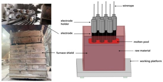
Figure 1.
Schematic diagram of a six-electrode EFMF.
The production of fused magnesia is a complex physical and chemical process. Gas, solid, liquid, and arc plasma coexist in the furnace, and momentum, mass, and heat transfer are coupled. Online measurement is hardly realized. The key to producing large-sized fused magnesia is to master the real-time temperature distribution in the EFMF. Therefore, it is of great significance to advance in-depth research on the distribution of multiple physical fields in the EFMF for improving industrial competitiveness.
The smelting process of fused magnesia mainly includes two steps: heating melting and cooling crystallization. In the smelting process, the electric arc discharges and releases a large amount of heat, which makes the raw material melt by heating. Due to the high resistance of magnesium oxide, the heat generated by magnesium oxide melt will accelerate the expansion of the molten pool. The relevant characteristics of the molten pool will directly affect the quality of the cooling crystallization to a certain extent. To improve the smelting technology and improve the deficiencies of the existing production process, it is necessary to understand the process mechanism and physical phenomena of the melting and growth of the molten pool. However, due to the harsh production environment and complex process, many production parameters, such as internal temperature, molten pool state, and arc combustion, are difficult to obtain through experimental measurement or online monitoring. Therefore, the use of the numerical simulation method to study the work of the EFMF is now a common method used by researchers.
The EFMF belongs to submerged arc furnaces in terms of working principle. There are many studies on submerged arc furnaces, involving research on the arc and molten pool [11]. Elkoumy et al. [12] studied the refining stage of the electric arc furnace. They established a three-dimensional electric arc furnace model to analyze the flow characteristics and heat transfer laws of the molten pool, and they compared the effects of natural convection stirring and forced convection stirring. Karalis et al. [13] studied the influence of electrode shape, immersion depth, and slag properties on the performance and mainly analyzed the potential, current density, Joule heat, temperature, and flow in the electric arc furnace. Halvorsen et al. [14] carried out a numerical simulation of a submerged arc furnace and completed the model establishment and division of electrodes and coke beds. However, in the actual smelting process, the current distribution in the material is unstable. Florin et al. [15] established a numerical model of a three-phase electric arc furnace to analyze the electromagnetic field and temperature field and calculated the Joule power density with AC electromagnetic analysis. The results showed that electromagnetic stirring with higher efficiency can be produced by injecting a DC or an AC low-frequency current into the bottom electrode for a large molten pool. Kiyoumarsi et al. [16] established a three-dimensional finite element model for the AC three-phase arc furnace including electrodes, arc area, and molten pool. The arc was set as an electric heating device with electric energy as the input and thermal energy as the output. The research results predicted the current density, voltage, and magnetic field intensity well. In the research of the EFMF, Wang et al. [17] developed a magnetohydrodynamic model of the arc plasma to calculate the arc voltage, power, and pressure distribution on the melt pool surface during the smelting process but did not consider the gas outflow and the movement of the solid–liquid partition interface. Wang et al. [18] conducted modeling research on a twin-electrode DC arc furnace. They obtained detailed information, such as voltage drop and arc heating power, and analyzed the temperature field and flow field of the molten pool. Wang et al. [19] studied the 3000 kVA and 1500 kVA AC electric arc furnaces. By comparing the bath size, temperature distribution ,and electromagnetic stirring effect, they found that large-capacity furnaces could save energy and increase production. Zhang et al. [20] proposed a novel process monitoring method to monitor the current of the furnace, which can determine whether the furnace is operating properly in different operating modes. In addition, the unstable air pressure in the furnace can cause material splattering and energy waste in the production process, so Fu et al. [7] designed a splattering suppression system based on an acoustic signal in order to reduce energy consumption by linking the noise during production to the production condition. Jiang et al. [21] conducted a comprehensive energy and compact analysis of a three-electrode AC magnesium sand furnace, and the production process was divided into MOP and LMP according to the different raw materials, and the energy efficiency of the two production processes was obtained as 62.2% and 65.5%, respectively; in addition, the energy efficiency of the LMP preparation process was only 39.4%. However, in the above studies, they all ignored the chemical reactions in the furnace, which may generate significant heat transformation. Therefore, some scholars have conducted more detailed studies. Scheepers et al. [22] established a three-dimensional finite element model, considered the reaction kinetics in the furnace, mainly the consumption of P2O5, and obtained information about temperature, flow, and chemical reaction area in the furnace. Zhang et al. [23] added the reaction heat of calcium oxide reacting with coke to generate CaC2 and CO into the energy equation and studied the electromagnetic field, temperature distribution, and molten pool in the smelting process. The thermochemical reactions and relationships within a three-phase AC arc furnace were modeled by Logar et al. [24]. The simulation results were compared with the available measurements to verify the reliability of the model. The thermochemical reaction model was coupled with the developed electrical and thermal model to obtain a complete model of the electric arc furnace, which can be used to guide the production and achieve a reduction in energy and cost consumption.
As the used material is high-purity magnesite, the main chemical reaction in the EFMF is the decomposition reaction of magnesium carbonate. Liu et al. [25] studied the thermal decomposition kinetics at different heating rates and finally obtained that the mechanism function was the anti-Jander equation, and the apparent activation energy (E) and pre-exponential factor (A) were 156.12 kJ/mol and 105.61 s−1, respectively. Tian et al. [26] obtained that the mechanism function was first-order reaction; E was between 199.99 and 206.37 kJ/mol, and the decomposition reaction was completely decomposed at 973 K. Longo et al. [27] studied the decomposition of magnesium carbonate under different conditions, and the results showed that the reaction rate of the reaction was large even at a moderate temperature.
To conclude, there are few studies on the distribution of multiple physical fields in the EFMF at present, and the impact of the decomposition reaction has not been considered in previous studies. In addition, most of the studied arc furnaces are two-electrode or three-electrode arc furnaces, and there are few studies on six-electrode arc furnaces. In order to overcome the above problems, this paper establishes a multiphysical field coupling model in a six-electrode EFMF to study the electromagnetic field, temperature distribution, and molten pool variation in the production process. The influence of current on the production is also analyzed to provide some guidance to the production.
2. Mathematical Models and Boundary Conditions
The present work involves the coupling electromagnetic field, temperature distribution, and flow field. Based on the finite volume method, Maxwell’s equations, continuity equation, momentum conservation equation, and energy conservation equation were used to describe the behavior and characteristics of the molten pool in the furnace.
2.1. Electromagnetic Field Description
The furnace uses 50 Hz alternating current, and the displacement current and charge density can be neglected. The following simplified Maxwell’s equations are obtained:
where is the electric field intensity, N/C; is the magnetic flux density, T; is the magnetic field intensity, A/m; is the current density, A/m2.
The constitutive equations are
where is the magnetic permeability; is the electrical conductivity.
By introducing the scalar potential and the vector potential , the following equation can be obtained combining Equations (2) and (3) [28,29]:
According to Ohm’s law and Coulomb gauge, we can obtain:
Thus, we can use the UDF in Fluent to perform the electromagnetic field calculation.
Then, the Joule heat and Lorentz force can be calculated as follows:
Next, Joule heat and Lorentz force are added to the energy conservation equation and momentum conservation equation in the form of source terms, respectively.
2.2. Continuity Equation
The general expression is:
where is the density, kg/m3; is the velocity vector, m/s; is the time, s.
2.3. Solidification and Melting Model
In the production of fused magnesia, the process of melting and solidification of the material occurs. The Solidification and Melting model is used to describe the phase-change problem. However, instead of explicitly tracing the interface between the solid phase and the liquid phase, the model treats the mixing zone where both the solid phase and liquid phase exist as the porous zone with porosity equal to the liquid phase fraction, called the mushy zone. On this basis, the momentum conservation equation is updated to account for the pressure drop due to the presence of solid-phase materials. The volume fraction of the liquid phase in this zone is defined as:
The momentum conservation equation is expressed as:
where is the pressure, Pa; is the viscosity, Pa·s; is the gravity acceleration vector, m/s2; is the mushy zone constant, 100,000; is constant, 0.001; is the liquidus temperature, K; is the solidus temperature, K; is the source term. The mushy zone constant represents the amplitude of the damping, and the larger the value, the faster the transition of the material velocity to 0 during solidification.
The energy conservation equation is expressed as:
where , is the effective thermal conductivity; is the apparent enthalpy, J/m3; is the latent heat, J/kg; is the Joule heat source term; is the energy source term.
2.4. Chemical Reaction
The main component of magnesite is magnesium carbonate (MgCO3). Therefore, only the decomposition reaction of MgCO3 is considered in this paper, as shown in Equation (18).
According to the experiment of Liu et al. [25], in their work, they indicate that the decomposition reaction occurs at 673~1073 K, which means all the magnesium carbonates is converted to MgO when the higher temperature is reached, and they identify that the activation energy of the reaction is E = 156.12 kJ/mol, and the pre-exponential factor is A = 105.61 s−1.
The change in the mass fraction of MgCO3 is calculated from the following equation:
where is the density, kg/m3; is the mass fraction; is the reaction amount; is the diffusion coefficient; is the reaction rate; is the molar mass.
The reaction rate of the decomposition reaction can be obtained from the chemical reaction rate constant .
where R is the molar gas constant.
In addition, in order to simulate the motion of the top surface of the material and the bottom of the electrode when smelting, the dynamic mesh model was used. In the present work, we assumed that the rate of rise of the top surface of the material and the bottom of the electrode remains the same, which means the relative positions of the two do not change during the smelting stage.
2.5. Physical Model
In this paper, the research subject is a six-electrode EFMF, and the electrodes of the furnace consist of two groups of three-phase electrodes. The same group of electrodes forms a square triangle, and the two groups are inverted from each other. One group is arranged clockwise by phase, and the other group is arranged counterclockwise. The production process can be divided into three stages: the starting stage, the smelting stage, and the cooling stage. Firstly, the furnace in the starting stage was studied, ignoring the electrodes in the calculation domain, as shown in Figure 2, and the specific parameters are shown in Table 1. The grid adopts the structured grid division method; the number of grids is about 150,000, and the quality is above 0.5, which meets the calculation requirements.
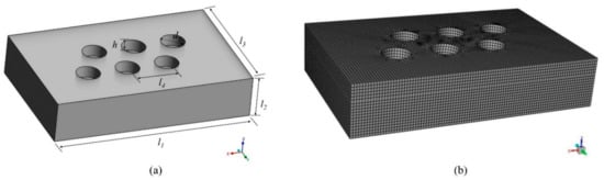
Figure 2.
Calculation domain and mesh. (a) Geometric model; (b) Schematic diagram of the grid.

Table 1.
Geometry parameter of the model.
2.6. Boundary Condition
An AC current density boundary condition is added to the bottom of the electrode, which can be expressed as [30]:
where is the RMS value of the operating current, A; is the cross-sectional area of the electrode, m2; is the frequency, 50 Hz; is the time, s; k = 0, 1, 2.
The rest of the initial boundary conditions are shown in Table 2, including scalar potential, vector potential, and temperature and heat transfer coefficients with the external environment. The physical parameters of MgO can be learned from Refs. [31,32].
Table 2.
Boundary conditions.
2.7. Numerical Details
In this work, the commercial CFD software Fluent computer code was applied as the computational platform; a pressure-based solver was adopted, and the SIMPLE algorithm was employed for pressure–velocity coupling. All the cases were carried out by transient simulations, and the time step was set to 0.75 s in a typical case. The convergence criteria for energy were 10−6, while the other convergence criteria were 10−4. The simulation of the starting stage ran around 3 days at a PC with 10 cores and 2.40 GHz.
3. Results and Discussion
In this work, the first two production stages were studied: the starting stage and the smelting stage. The goal of the starting stage is to form a certain-sized molten pool, and the goal of the smelting stage is to keep the current stable to produce continuously.
3.1. Electromagnetic Field Analysis
The internal heat source of the EFMF is mainly arc heat. Therefore, the working current is bound to affect the production. It is necessary to understand the electromagnetic field inside the furnace. As shown in Figure 3, different cross-sections were taken to show the current density inside the furnace (Plane A: y = 0.29445 m; Plane B: z = 0.5 m). The current density is concentrated near the electrode, and there is no current even at the furnace wall far from the electrode. This phenomenon is caused by the low electrical conductivity of MgO. Because the electrical conductivity is related to the temperature, the conductivity of the cold material is much smaller than that of the molten material. Due to the way the electrodes are arranged, the current can also flow through a shorter path from one electrode to another group of electrodes, as shown by the red arrow in the figure, thus reducing the low current area and reducing the power loss.
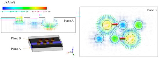
Figure 3.
Current density distribution in the furnace (I = 10,500 A).
Figure 4 shows the variation of Joule heat in the furnace. From Equation (12), Joule heat is proportional to the square of the current density. Due to the uneven distribution of current density, Joule heat is concentrated in the region below the electrodes and decreases as the distance from the bottom of the electrodes increases. Because the three electrodes in Plane A are in different phases, we also observed that the maximum value of Joule heat alternates with time at the bottom of the electrodes.
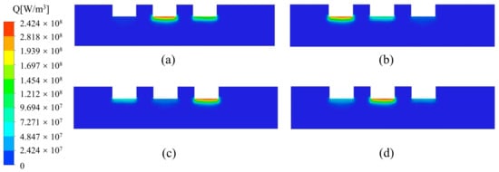
Figure 4.
Variation of Joule heat distribution in the furnace with time (I = 10,500 A). (a) 15 min; (b) 30 min; (c) 45 min; (d) 60 min.
3.2. Temperature Field Analysis at Starting Stage
At the production site, the starting stage lasts 1 h. Figure 5 shows the temperature distribution at the end of the starting stage. A large part of the temperature zone below the electrodes reaches above 3000 K, which is higher than the melting point of magnesium oxide, and melting occurred. A certain-sized molten pool forms under each electrode, but the molten pool is not yet connected. Due to the high refractoriness of magnesium oxide, a large temperature gradient exists at the boundary of the melt pool, and the temperature at the furnace wall is very low, which is the characteristic of the fused magnesia production.
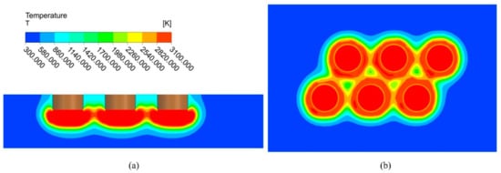
Figure 5.
Temperature distribution at the end of starting stage (I = 10,500 A). (a) Plane A; (b) Plane B.
In Figure 6, the temperature inside the furnace is compared for different operating current sizes, and the temperature maximum occurs directly below the electrode. As the current size increases, the high temperature region is significantly increased. At a current of 10,500 A, the temperature profile between the electrodes shows that there is still a small area where the temperature is below 3000 K. When the current size increases to 12,500 A, the temperature between the electrodes is greater than 3000 K, which indicates that the molten pool under the electrodes starts to be connected and reach the production requirements. Therefore, when the current size is greater than 10,500 A, the EFMF can operate normally.
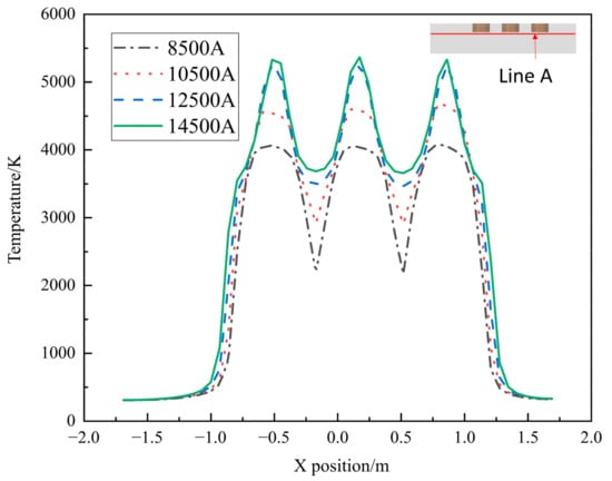
Figure 6.
Temperature with different current sizes along line A.
3.3. Decomposition Reaction at Starting Stage
Figure 7 shows the distribution of the magnesium carbonate in the furnace, and the volume of material with a mass fraction of 0. As shown in Figure 7a, there is a large mass fraction gradient, which is due to the fast decomposition of magnesium carbonate. When the decomposition reaction takes place in the furnace, the magnesium carbonate is converted into magnesium oxide. When the mass fraction of magnesium carbonate is 0, it means that the material is converted to pure magnesium oxide at this point, which is what the production wants to achieve. This part of the material converted to pure magnesium oxide is shown in Figure 7b. In Figure 8, the change in volume of the converted pure magnesium oxide is counted for different operating current sizes. The volume increases significantly as the current increases. However, the amount of CO2 produced is proportional to the amount of magnesium carbonate reacted, so the amount of CO2 is also increasing, which puts great pressure on the environment. The right axis in Figure 8 represents the CO2 generation rate, i.e., the ratio of volume to current. The generation rate increases with the current, so a small operating current size can reduce the pollution pressure.
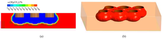
Figure 7.
Mass fraction distribution of magnesium carbonate in furnace (I = 10,500 A). (a) Mass fraction distribution of Plane A; (b) Volume of material with mass fraction of 0.
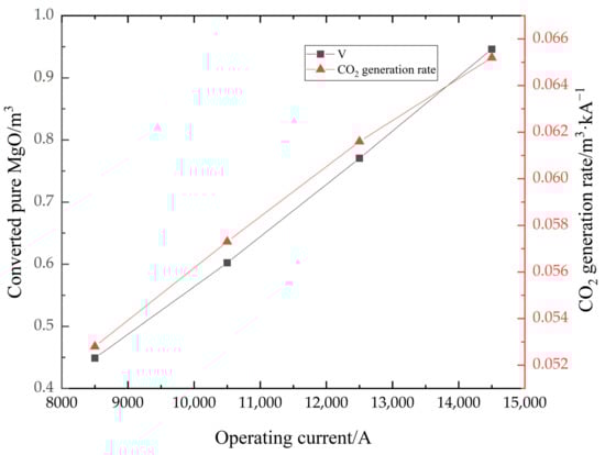
Figure 8.
The totally reacted volume and CO2 generation rate in different current sizes.
3.4. Smelting Stage Analysis
The smelting stage is the process in which production proceeds steadily, as shown in Figure 9a. This process requires not only that the material is melted quickly, but also that a certain molten pool depth is maintained. Maintaining the depth of the molten pool needs an appropriate Joule heat power. High power will cause material spattering, but also cause local overheating and even burn through the furnace wall. Low power will cause the material to smelt slowly and will not allow the smelting to continue steadily. The smelting time required for the EFMF studied in this paper is 8 h. During the smelting stage, with the addition of material and the installation of a removable furnace shell, the furnace height can finally reach 3.86 m, which means that the calculation domain changes. We coupled the dynamic mesh model to simulate this process. The calculation domain and mesh of the smelting phase are shown in Figure 9b, and the number of grids was finally determined as 1.07 million after grid independence verification.
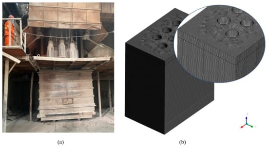
Figure 9.
(a) EFMF in the smelting stage; (b) Calculation domain and mesh at the end of smelting stage.
Figure 10 shows the average wall temperature during the smelting stage. The maximum temperature can reach 440.24 K when the melting proceeds to 8 h, as shown in Figure 11. However, considering the good thermal conductivity of the furnace shell, the average wall temperature variation with the melting time was counted. The rate of temperature rise of the furnace wall increases during 8 h of the smelting process. The temperature of 317.54 K can be reached at the end, which is in good accordance with the actual production situation. However, we still need to pay attention to the local overtemperature phenomenon that may occur during the working process due to an unstable operating current or a large operating current, which can cause leakage of the furnace.
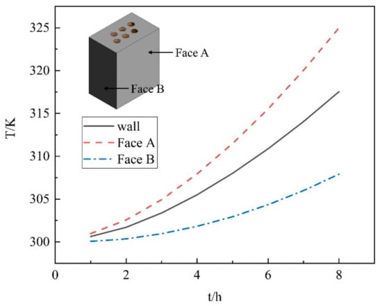
Figure 10.
The average wall temperature over time.
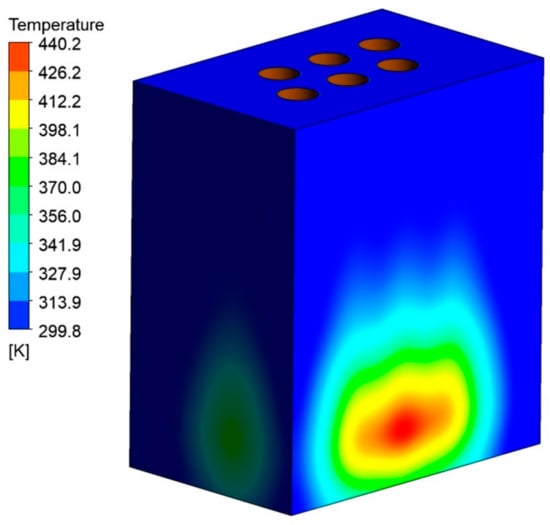
Figure 11.
The temperature distribution at the end of the smelting stage.
4. Conclusions
In this paper, the magnetic–fluid–thermal multiphysical field phenomena in the production process were studied in a six-electrode electric-fused magnesia furnace, and the following conclusions were obtained from a detailed analysis of the two stages in production:
(1) Because the two groups of three-phase electrodes are arranged in an inverted triangular pattern, the three electrodes in the same row are in different phases, so that the current can flow in a shorter path, thus reducing the power consumption. Due to the low electrical conductivity of the material, the current density and Joule heat are concentrated in the area below the electrodes.
(2) The formation of a certain-sized molten pool is the basis for stable production during the furnace starting stage. At the working current of 10,500 A, the area of temperature below the melting point between the electrodes is already small. When the current size is 12,500 A, the molten pool below the electrodes is connected, so the operating current should not be less than 10,500 A. Considering the CO2 produced by the decomposition of magnesite, the best-recommended operating current of this furnace is 12,500 A.
(3) The wall average temperature can only reach 317.54 K at the end of the smelting stage, but the highest temperature of the material at the wall reached 417 K. So, the operating current needs to be controlled to prevent the local temperature from being too high.
Author Contributions
Writing—original draft, Methodology, and Conceptualization, F.Q.; Methodology and Data curation, Y.H.; Validation and writing—review and editing, J.X.; Writing—review and editing, B.L. All authors have read and agreed to the published version of the manuscript.
Funding
This work was funded by The National Science Foundation of China (52174305).
Data Availability Statement
Not applicable.
Conflicts of Interest
The authors declare that they have no conflict of interest.
References
- Naoi, T.; Lin, H.; Hirota, A.; Otani, E.; Amemiya, K. Improved discharge characteristics using MgO single-crystal particles and advanced CEL structure. J. Soc. Inf. Disp. 2009, 17, 113–119. [Google Scholar] [CrossRef]
- Schroeder, J.L.; Ingason, A.S.; Rosén, J.; Birch, J. Beware of poor-quality MgO substrates: A study of MgO substrate quality and its effect on thin film quality. J. Cryst. Growth 2015, 420, 22–31. [Google Scholar] [CrossRef]
- Malfliet, A.; Lotfian, S.; Scheunis, L.; Petkov, V.; Pandelaers, L.; Jones, P.T.; Blanpain, B. Degradation mechanisms and use of refractory linings in copper production processes: A critical review. J. Eur. Ceram. Soc. 2014, 34, 849–876. [Google Scholar] [CrossRef]
- Ramakrishnan, S.; Koltun, P. Global warming impact of the magnesium produced in China using the Pidgeon process. Resour. Conserv. Recycl. 2014, 42, 49–64. [Google Scholar] [CrossRef]
- Zhao, L.; Feng, J.; Dong, H. Analysis of carbon footprint and reduction approach of magnesia production in China. J. Clean. Prod. 2022, 334, 130194. [Google Scholar] [CrossRef]
- Li, T.; Wang, Z.; Wang, N. Temperature Field Analysis and Process Control Strategies for MgO Single Crystal Production Using Adaptive Neuro-Fuzzy Inference System. Open Mater. Sci. J. 2011, 5, 162–169. [Google Scholar] [CrossRef]
- Fu, Y.; Wang, Z.; Wang, Z.; Wang, N.; Wang, X. Splattering Suppression for a Three-Phase AC Electric Arc Furnace in Fused Magnesia Production Based on Acoustic Signal. IEEE Trans. Ind. Electron. 2017, 64, 4772–4780. [Google Scholar] [CrossRef]
- Wu, Z.; Wu, Y.; Chai, T.; Sun, J. Data-Driven Abnormal Condition Identification and Self-Healing Control System for Fused Magnesium Furnace. IEEE Trans. Ind. Electron. 2015, 62, 1703–1715. [Google Scholar] [CrossRef]
- Qi, G.C.; Shan, F.J.; Li, Q.; Yu, J.Y. Analysis of Fused Magnesia Production Process with 3000kVA Electric Arc Furnace. Appl. Mech. Mater. 2013, 275, 2143–2147. [Google Scholar] [CrossRef]
- Li, J.; Zhang, Y.; Shao, S.; Zhang, S. Comparative life cycle assessment of conventional and new fused magnesia production. J. Clean. Prod. 2015, 91, 170–179. [Google Scholar] [CrossRef]
- Yang, J.; Lu, S.; Wang, L. Fused magnesia manufacturing process: A survey. J. Intell. Manuf. 2020, 31, 327–350. [Google Scholar] [CrossRef]
- Elkoumy, M.M.; El-Anwar, M.; Fathy, A.M.; Megahed, G.M.; El-Mahallawi, I.; Ahmed, H. Simulation of EAF refining stage. Ain Shams Eng. J. 2018, 9, 2781–2793. [Google Scholar] [CrossRef]
- Karalis, K.T.; Karkalos, N.; Cheimarios, N.; Antipas, G.S.; Xenidis, A.; Boudouvis, A.G. A CFD analysis of slag properties, electrode shape and immersion depth effects on electric submerged arc furnace heating in ferronickel processing. Appl. Math. Model. 2016, 40, 9052–9066. [Google Scholar] [CrossRef]
- Halvorsen, S.A.; Olsen, H.A.; Fromreide, M. An efficient simulation method for current and power distribution in 3-phase electrical smelting furnace*. IFAC-PapersOnline 2016, 49, 167–172. [Google Scholar] [CrossRef]
- Florin, D.; Tiberiu, T.; Viegiliu, F. Numerical evaluation of electromagnetic field effects in electric arc furnaces. COMPEL Int. J. Comput. Math. Electr. Electron. Eng. 2001, 20, 619–635. [Google Scholar]
- Kiyoumarsi, A.; Nazari, A.; Ataei, M.; Beheshti, H.K.; Hooshmand, R.A. Electromagnetic analysis of an AC electric arc furnace including the modeling of an AC arc. COMPEL Int. J. Comput. Math. Electr. Electron. Eng. 2010, 29, 667–685. [Google Scholar] [CrossRef]
- Wang, Z.; Wang, N.H.; Li, T.; Cao, Y. 3D Numerical Analysis of the Arc Plasma Behavior in a Submerged DC Electric Arc Furnace for the Production of Fused MgO. Plasma Sci. Technol. 2012, 14, 321–326. [Google Scholar] [CrossRef]
- Wang, Z.; Wang, N.H.; Li, T. Computational analysis of a twin-electrode DC submerged arc furnace for MgO crystal production. J. Mater. Process. Technol. 2011, 211, 388–395. [Google Scholar] [CrossRef]
- Wang, Z.; Fu, Y.; Wang, N.; Feng, L. 3D numerical simulation of electrical arc furnaces for the MgO production. J. Mater. Process. Technol. 2014, 214, 2284–2291. [Google Scholar] [CrossRef]
- Zhang, Y.; Wang, C.; Lu, R. Modeling and monitoring of multimode process based on subspace separation. Chem. Eng. Res. Des. 2013, 91, 831–842. [Google Scholar] [CrossRef]
- Jiang, T.C.; Zhang, W.J.; Liu, S. Performance Evaluation of a Full-Scale Fused Magnesia Furnace for MgO Production Based on Energy and Exergy Analysis. Energies 2022, 15, 214. [Google Scholar] [CrossRef]
- Scheepers, E.; Adema, A.T.; Yang, Y.; Reuter, M.A. The development of a CFD model of a submerged arc furnace for phosphorus production. Miner. Eng. 2006, 19, 1115–1125. [Google Scholar] [CrossRef]
- Zhang, X.K.; He, Y.L.; Tang, S.Z.; Wang, F.L.; Xie, T. An electromagnetics-temperature-component multi-physical coupled model for electric furnace in calcium carbide smelting process. Appl. Therm. Eng. 2020, 165, 114552. [Google Scholar] [CrossRef]
- Logar, V.; Dovžan, D.; Škrjanc, I. Modeling and Validation of an Electric Arc Furnace: Part 2, Thermo-chemistry. ISIJ Int. 2012, 52, 413–423. [Google Scholar] [CrossRef]
- Liu, X.W.; Feng, Y.L.; Li, H.R.; Zhang, P.; Wang, P. Thermal decomposition kinetics of magnesite from thermogravimetric data. J. Therm. Anal. Calorim. 2012, 107, 407–412. [Google Scholar] [CrossRef]
- Tian, L.; Tahmasebi, A.; Yu, J. An experimental study on thermal decomposition behavior of magnesite. J. Therm. Anal. Calorim. 2014, 118, 407–412. [Google Scholar] [CrossRef]
- Longo, G.M.; Longo, S. Thermal decomposition of MgCO3 during the atmospheric entry of micrometeoroids. Int. J. Astrobiol. 2017, 16, 368–378. [Google Scholar] [CrossRef]
- Tesfahunegn, Y.A.; Magnusson, T.; Tangstad, M.; Saevarsdottir, G. Effect of electrode shape on the current distribution in submerged arc furnaces for silicon production—A modelling approach. J. S. Afr. Inst. Min. Metall. 2018, 118, 595–600. [Google Scholar] [CrossRef]
- Tesfahunegn, Y.A.; Magnusson, T.; Tangstad, M.; Saevarsdottir, G. Dynamic Current Distribution in the Electrodes of Submerged Arc Furnace Using Scalar and Vector Potentials. In Proceedings of the ICCS 2018, Wuxi, China, 11–13 June 2018. [Google Scholar]
- Moghadam, M.M.; Seyedein, S.H.; Aboutelebi, M.R. Fluid Flow and Heat Transfer Modeling of AC Arc in Ferrosilicon Submerged Arc Furnace. J. Iron Steel Res. Int. 2010, 17, 14–18. [Google Scholar] [CrossRef]
- Ye, D.; Hu, J. Practical Thermodynamic Data Handbook of Inorganic Substances, 2nd ed.; Metallurgical Industry Press: Beijing, China, 2002; pp. 561–562. [Google Scholar]
- Arkel, A.V.; Flood, E.; Bright, N.F. The electrical conductivity of molten oxides. Can. J. Chem. 1953, 31, 1009–1019. [Google Scholar] [CrossRef]


Disclaimer/Publisher’s Note: The statements, opinions and data contained in all publications are solely those of the individual author(s) and contributor(s) and not of MDPI and/or the editor(s). MDPI and/or the editor(s) disclaim responsibility for any injury to people or property resulting from any ideas, methods, instructions or products referred to in the content. |
© 2023 by the authors. Licensee MDPI, Basel, Switzerland. This article is an open access article distributed under the terms and conditions of the Creative Commons Attribution (CC BY) license (https://creativecommons.org/licenses/by/4.0/).