Article

Bifurcation Analysis of a Rotor-Casing Coupling System with Bolted Flange Connection under the Effect of Rotor-Casing Rubbing Fault

1
School of Mechanical and Automotive Engineering, Guangxi University of Science and Technology, Liuzhou 545006, China
2
School of Electronic Engineering, Guangxi University of Science and Technology, Liuzhou 545006, China
3
Guangxi Earthmoving Machinery Collaborative Innovation Center, Guangxi University of Science and Technology, Liuzhou 545006, China
*
Author to whom correspondence should be addressed.
Processes 2023, 11(5), 1301; https://doi.org/10.3390/pr11051301
Submission received: 22 March 2023 / Revised: 7 April 2023 / Accepted: 19 April 2023 / Published: 22 April 2023
(This article belongs to the Section Energy Systems)

Abstract

:
This study mainly investigated the nonlinear vibration performance of a rotor-casing coupling system containing a bolted flange connection. The dynamic equations of the coupling system were developed while considering the radial stiffness of the bolted flange structure, which contained a spigot, squirrel cage with ball bearing, and rotor-casing coupling vibration. To study the influence of the disk casing fixed-point rubbing fault on the coupling system’s nonlinear dynamic performance, an analytical model of the nonlinear impact forces was established, which considered the contact and vibration responses of the rotor and casing. The frictional force was obtained based on the Coulomb friction law. The iterative analysis of motion equations was performed utilizing the Newmark method. Then, the nonlinear dynamic behaviors of the coupled systems were examined using data, including a bifurcation diagram, spectrum plot, greatest Lyapunov exponents, etc. The effects of rubbing fault on the dynamic properties of system were investigated in detail, indicating that there were various motion states, which were described as periodic, multi-periodic, and quasi-periodic motions. Comparing the simulation results, it was found that rubbing fault seriously affected the motion stability of the rotor system. Finally, by gathering and examining the vibration data set from a test platform for rotor-casings with bolted joints, the correctness of the numerical simulation findings was confirmed. Additionally, the results of the experimental investigation agreed with that of the simulation. The dynamic distinguishing characteristics that were noticed can be used as an indicator for determining whether the fixed-point rubbing fault between the rotor and casing has become worse.

1. Introduction

Rotor-casing rubbing faults have attracted considerable interest in studies aiming to reduce the rotor–stator clearance to achieve a high efficiency for turbomachines [1,2,3]. When a rubbing fault happens, very complicated dynamic properties, including quasi-periodic motion, period doubling bifurcation, or even chaotic motion, can also appear in the case of simple rotor systems. The casing will also experience significant excitation force that is imposed by the rotor-casing rub impact. When a rubbing fault develops, the coupling mechanism of the rotor-casing system results in exceedingly complicated vibration behaviors throughout the entire system. Therefore, a thorough analysis of the nonlinear dynamic properties of the rotor-casing coupling system is necessary to diagnose the worsening of the fixed-point rubbing faults. Moreover, mechanical joints are usually used in engineering structures to fasten multiple substructures into an integrated structure [4,5]. In turbomachines, bolted flange connections with a spigot are the most used structures to hold adjacent disks together because of their simplicity and ability to provide sufficient stiffness for energy transfer [6,7]. The local stiffness of a bolted flange connection results in a completely different stiffness characteristic compared with an integrated rotor. Therefore, the study of the rub-impact characteristics in a rotor-casing coupling system should consider the bolted flange connection in turbomachines.
A great deal of work has been conducted over the years to reveal the nonlinear phenomena of rotor systems under rotor–stator rubbing faults from different viewpoints. For example, according to the requirements of an understanding of rotor failure mechanisms and nonlinear dynamics, Behzad et al. [8] used several elastically mounted arc-shaped rigid bodies to simulate the stator, and the nonlinear vibration performance of a flexible rotor–stator system was revealed by combining a Jeffcott rotor model. Subsequently, the reverse rubbing behaviors of a rotor system with a non-annular, three-lobed rubbing structure were investigated by Behzad et al. [9] using numerical simulation and experimental verification. Briend et al. [10] inquired into the vibration feature of the dry-whip phenomenon during rotor–stator contact that is caused by base excitations, and the impact of the base excitation’s amplitude and direction on the nonlinear rotor’s dynamic performance was evaluated. Based on Lagrange equations, Zhang et al. [11] derived a mathematical model of a hydraulic generating set rotor system that was subjected to rub-impact forces and thoroughly investigated the influence of the excitation current, contact stiffness of the stator, and eccentric force on the hydraulic generating set rotor system. Gao et al. [12] devoted a study to the nonlinear vibration behavior of a rotor system during a barrel roll flight working condition that considered the rub-impact fault. The multiple scales approach was utilized by Kandil et al. [13] to demonstrate the nonlinear dynamic characteristics of an active magnetic bearing rotor system with a rub-impact flaw. Yang et al. [14,15] experimentally and analytically studied the nonlinear dynamic properties of a dual-rotor system with a rub-impact fault and further analyzed the influence of the rotational speed ratio, eccentric phase difference, and multiple coupling fault on system responses. Zhang et al. [16] derived the dynamic model of the rod fastening rotor with a multi-fault, including rubbing and crack faults, and explored the interaction of multiple faults. The result reflects that a multi-fault enhances the nonlinear behavior of the rotor system. Mokhtar et al. [17] developed a numerical model of a rotor system based on the finite element beam theory and studied the rotor–stator contact phenomenon of the turbopump during the coast-up vibration. Zeng et al. [18] employed self-programmed element and finite element methods to study the contact behavior between the rotor and stator and showed that the stator dynamic response is more sensitive to resonance. Kang et al. [19] explored the effect of the rubbing process and forms on the dynamic performance of rotor–blade–casing systems and found that more blades being involved in rubbing would enhance the nonlinear characteristic of the system. Wang et al. [20] analyzed a dual-rotor system that considered the fixed-point rubbing fault and observed that second backward and forward whirling frequencies exist in the spectrum plots. The observed simulation results were validated with experimental results. Liu et al. [21] analytically investigated the Hopf bifurcation phenomenon of an active magnetic bearing-supported rotor system that made contact with auxiliary bearings. For a further complete overview of rotor–stator rubbing fault dynamics, extensive reviews can be found in [22].
In the past few years, research on modeling the rotor system with a bolted connection structure and research exploring the nonlinear behaviors of this kind of rotor system has intensified even more. For instance, Zhang et al. [23] proposed a dynamic modeling method for a multi-disk rod fastening rotor system that considered multiple parameter influences, and the authors studied the interaction of the system parameters and fault features in the composite rod fastening rotor system. Hong et al. [24] derived a novel bolted flange connection model that considered the breathing effect and asymmetric residual preload; the vibration performance of the jointed rotor system was revealed through in-depth numerical and experimental studies. Based on the lumped mass method, Li et al. [25,26] investigated the bifurcation and chaos behavior of the rod fastening rotor system, and the effect of nonuniform contact stiffness between the jointed parts was also evaluated. Qin et al. [27,28] investigated a simple disk–drum bolted joint rotor system to demonstrate how joint stiffness and bolt loosening affect the rotor dynamic behaviors. Li et al. [29] derived a semi-analytical model of a thin-walled cylindrical shell connected by a bolted flange and analyzed the dynamic response characteristics and contact state by considering the bilinear stiffness of the bolted joint. Wu et al. [30] and Wang et al. [31,32] developed a mathematical formula of jointed structures, and an in-depth discussion of the effect of joint stiffness on the vibration performance of the rotor system was conducted.
Based on a survey of the above literature, it can be found that the current research on rotor system rubbing faults has mainly been focused on the rotor–stator rubbing phenomenon; the coupling effect of the rotor and casing is always ignored, assuming that the stator is fixed. In the past few years, Mokhtar et al. [33], Wang et al. [34], and Yang et al. [35] established the rotor–stator coupling model, in which the rubbing forces can be transferred through the stator to rotor by the support structure. Then, the effect of contact stiffness and radial clearance on rubbing characteristics has been studied. However, the above research on the rubbing fault is limited to integral rotor systems, and the bolted flange connection in the rotor system is rarely considered in work on rotor-casing rubbing behaviors. In our previous works [36,37], the vibration behavior of the jointed rotor system with a fixed-point rubbing fault was investigated, which indicated there was a significant effect of the joint structure and rubbing fault on the dynamic behavior of rotor system. That is, the coupling effect of the vibration of the disk and casing and the effect of a bolted flange connection with a spigot on the dynamic behaviors of the rotor system has not been considered in the existing research works, which is a great innovation and is of research significance. Inspired by the works mentioned above, it was found that the joint stiffness and coupling effect of the rotor and casing affect the dynamic performance of the rotor system when rubbing fault occurs. Consequently, when incorporating the joint stiffness of a bolted flange connection with a spigot into the rotor model and considering the rub-impact fault on dynamic behaviors for the rotor-casing coupling system, the dissimilar phenomena can be comprehensively obtained from the dynamic responses, which is informative for fault diagnoses of rotor-casing coupling systems that are under unbalanced excitations and rubbing force.
Hence, in the present work, a coupled rotor-casing system with a bolted flange connection was modeled, where the vibration of the rotor and casing is transmitted through direct contact during the rub-impact and bearing support. The coupled rubbing force model for the rotor-casing system was constructed, and the corresponding motion equations of the coupling system are presented later in the work. The impacts of the interaction of the rotor and casing and the radial stiffness of the bolted flange connection are considered in the established dynamic model. Based on these factors, the dynamic performance of the coupling rotor system and influence of the rubbing fault were analyzed using numerical analysis methods. Then, a rotor-casing coupling system test rig was used for the experimental study. The correctness of the simulation findings can be demonstrated by comparing the numerical and experimental results. The observed findings of the current study may be considered a valuable indication for identifying the aggravation of fixed-point rubbing faults in rotor-casing coupling systems. Moreover, the research results could help researchers understand the dynamic properties of the rotor-casing coupling system with a joint structure under fixed-point rubbing faults, which contribute to fault identification, stability research, and structure design in joint rotor systems such as aero-engines, gas turbines, and wind-driven generators, as exhibited in Figure 1.

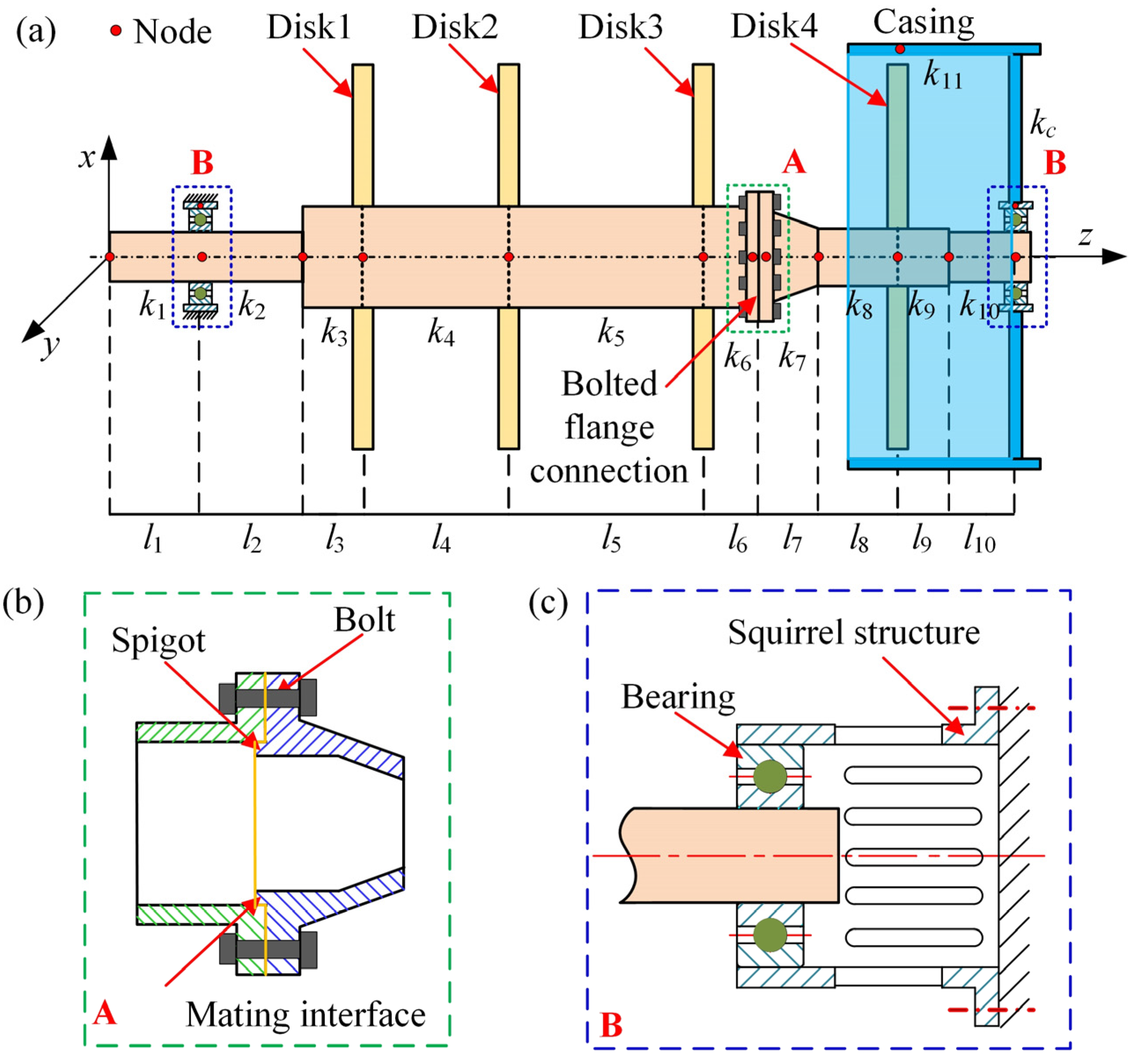
2. Dynamic Modeling of a Rotor-Casing Coupling System with Bolted Connection

In this section, an analytical model of the nonlinear impact forces that considered the contact and vibration responses of the rotor and casing was obtained based on the Coulomb friction law, and the model further derived the radial stiffness of the bolted joint using a bar model and partitioning characterization method. Furthermore, by combining the lumped mass modeling method and nonlinear bearing force, the dimensionless dynamic equations of the coupling system were developed in consideration of the radial stiffness of the bolted flange structure using a spigot, squirrel cage with ball bearing, and rotor-casing coupling vibration.
As shown in Figure 2, a rotor-casing coupling system with a bolted flange connection is supported by a squirrel cage structure with a bearing, and the vibration of the rotor is transmitted through direct contact during the rub-impact and through the squirrel structure (see Figure 2c). The rotor is composed of two shafts, where the bolted flange connection with a spigot is used to connect the shafts into an integrated one (see Figure 2b). To facilitate the modeling and analysis, the following assumptions were firstly made:
(a)
The rotor and casing are supposed to be rigid, and the central axis of the shaft and casing are parallel; thus, only the lateral vibration of the coupling system is considered;
(b)
The shaft segments shown in Figure 2a are massless; thus, the effect of the gyroscopic and polar moment of inertia can be neglected;
(c)
The vibration of the coupling system transmits through direct contact during the rubbing fault and through the squirrel structure;
(d)
The nonlinearities due to frictional contacts at the mating interface of the bolted flange connection during vibrations is ignored in the present work.

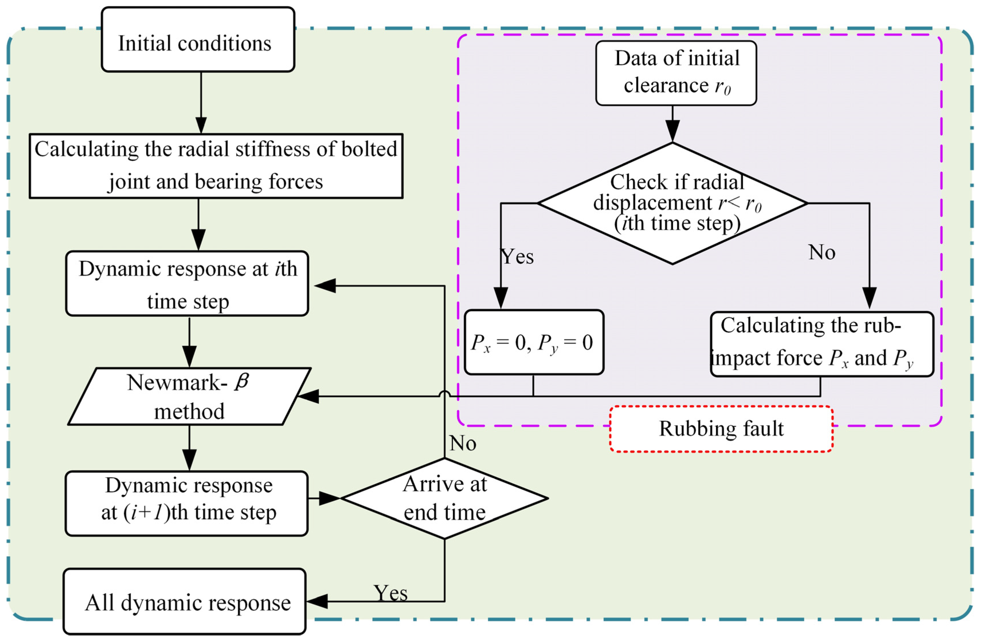
2.1. Rotor-Casing Rubbing Force Model

Figure 3 depicts a rubbing model for the rotor-casing coupling system. The operation speed of the rotor system is defined as ω, and the initial clearance between the rotor and the casing is defined as r0. kc is the stiffness between the casing and the squirrel structure, and xd, xc, yd, and yc are the lateral response displacements of the disk and casing. Then, based on the Coulomb friction law [38,39,40] and linear elastic deformation theory, the rubbing forces of the coupled system can be obtained as [41,42]:
P N = k r r r 0 P T = η P N         r r 0
where kr represents the contact stiffness of disk and casing; η represents the friction coefficient; and r denotes the radial displacement of the disk, r = x c x d 2 + y c y d 2 .
To facilitate the numerical solution, the rub-impact forces provided by friction and the radial contact should be transformed into x and y coordinates, described as:
P x = P N cos γ + P T sin γ P y = P N sin γ P T cos γ
where
sin γ = x d x c / x d x c 2 + y d y c 2 cos γ = y d y c / x d x c 2 + y d y c 2
Substituting Equation (3) into Equation (2), the friction force and the radial contact force can be derived in x- and y-directions as:
P x P y = cos γ sin γ sin γ cos γ P N P T = x d x c / r y d y c / r y d y c / r x d x c / r k r r r 0 η k r r r 0 = k r r r 0 r 1 η η 1 x d x c y d y c
Finally, the formulation of the rubbing forces used for the numerical analysis can be calculated using:
P x P y = k r r r 0 r 1 1 η η 1 x d x c y d y c   ,     r r 0 P x = P y = 0 ,       r < r 0

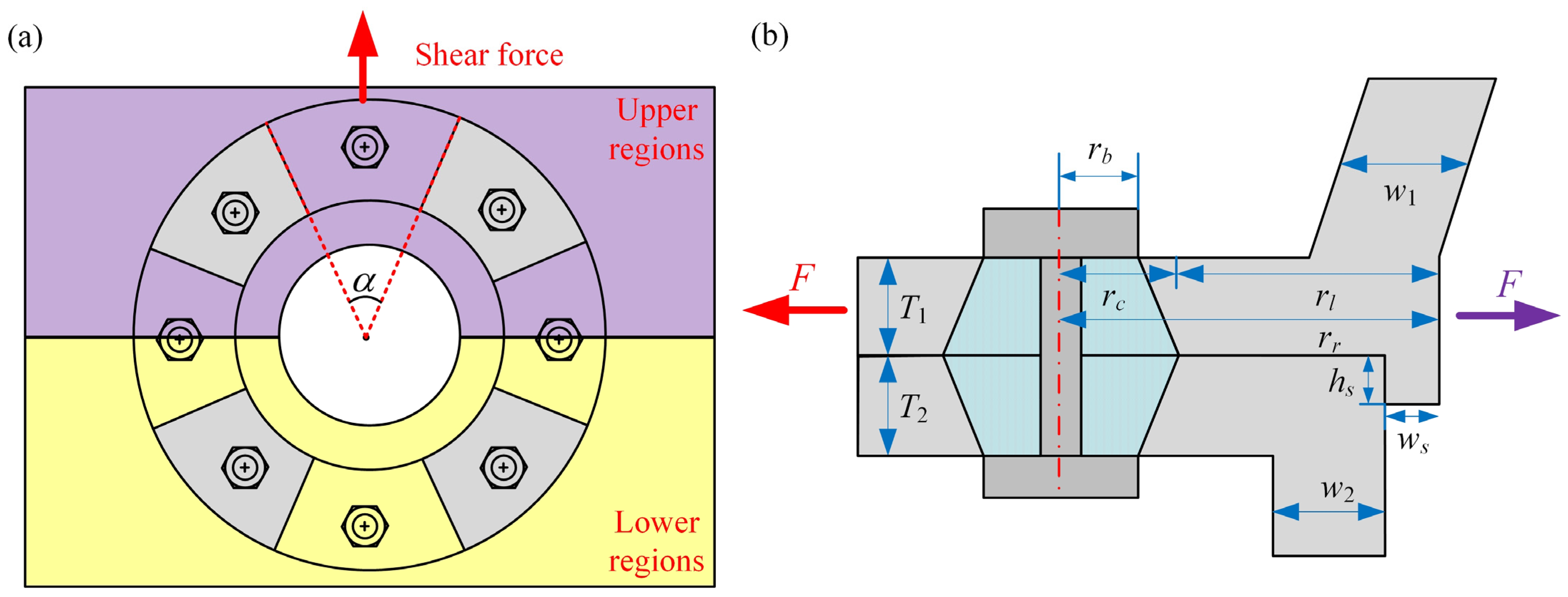
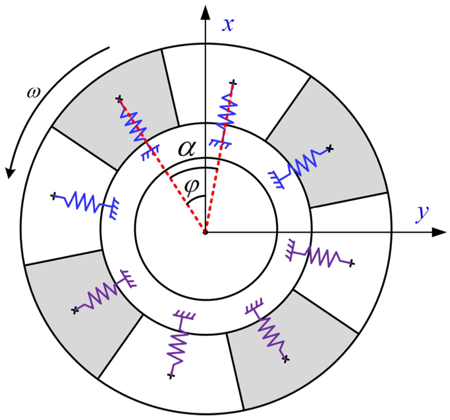
2.2. Modeling of the Bolted Flange Connection with a Spigot

The numerical formulation of the radial stiffness of a bolted joint structure with a spigot is described in this section, which takes into account the stress–strain relationship of the contact zone. For the rotor system, the analytical model may be utilized to examine the dynamic properties of the rotor system with bolted connections [43]. The radial stiffness can then be formulated by decomposing the whole structure into multiple single bolted regions due to the stress at the mating surface being composed of the preload of each bolt [4]; the divided regions are shown in Figure 4a. In this work, the slip behavior was supposed to not be generated due to the mating interface being in a sticking condition under the effect of the bolted joint and spigot. Therefore, the stiffness of the upper region was composed of the stiffness of the spigot and flange, the stiffness of the lower regions was the stiffness of the flange, and the radial shear force generated by the bow deformation during the operation was what caused the stiffness of those two regions. The mechanical behavior of the upper regions of bolted joint is demonstrated by the red arrow in Figure 4b, where the spigot will be deformed under a shear force. Instead, the spigot at the lower regions of the bolted joint will not be deformed under the shear force, which is illustrated by a purple arrow shown in Figure 4b.
In Figure 4a, the bolted joint is divided into several regions according to the number of bolts, and the parameters of each region are depicted in Figure 4b. To obtain the analytical formula of the radial stiffness of bolted joint, the stiffness of each flange and spigot should be obtained first. Then, the analytical model of the radial stiffness of the flange can be obtained using a bar model as follows [44]:
k f r = A E l = W T 1 E 1 / r l W T 2 E 2 / r l W T 1 E 1 / r l + W T 2 E 2 / r l = W T 1 E 1 T 2 E 2 r l T 1 E 1 + T 2 E 2
where W denotes the width of each region of bolted flange, which can be calculated by dividing the circumference by the number of bolts. T1 and T2 represent the thicknesses of the upper flange and lower flange, respectively. E1 and E2 are the elastic moduli of the flange, respectively.
According to Figure 4b, to acquire the parameter value of rl, the diameter of the compression zone rc should first be calculated using the following equation [45]:
r c = T a v g r b / T a v g 3 + 0.61 3 3 + 0.53 T a v g
where Tavg is the main value of the thicknesses of the flange. rb denotes the radius of the bolt head.
Moreover, according to the literature [44], the radial stiffness of the spigot can be defined by:
k s r = W H s R 1 E 1 r o 2 + R 2 r o 2 R 2 ν 1 + 1 E 2 R 2 + r i 2 R 2 r i 2 + ν 2
where R is the radius of the spigot. v1 and v2 represent the Poisson ratio of the upper and lower flange, respectively. ri and ro denote the inner and outer radius of the spigot, respectively. The other parameters are shown in Figure 4b.
Therefore, the radial stiffness of one upper region can be expressed as:
k u = k f r + k s r
The radial stiffness of one lower region opposite to the above-mentioned upper region is k f r due to the spigot of the lower region not being deformed. It is assumed that the radial stiffness of each divided region is consistent, along with the width of the bolted flange W; the mechanical behavior of the bolted joint along with the lateral direction is exhibited in Figure 4. Hence, the radial stiffness of bolted joint can be represented as:
k x r = i = 1 N / 2 k u cos β i + k f r cos β i + N / 2 k y r = i = 1 N / 2 k u sin β i + k f r sin β i + N / 2
where βi is the angle between the springs and the x-axis, as shown in Figure 5. N is the number of the bolts. It should be mentioned that β1 = αφ, where α = 2π/N and φ is the phase of eccentricity.

2.3. Motion Equations of the Rotor System

According to the rotor’s symmetry and assumptions made as mentioned above, the governing equation of the rotor-casing coupling system is established as follows:
M q ¨ x + C q ˙ x + K q x = F u x + F b x + P x M q ¨ y + C q ˙ y + K q y = F u y + F b y + P y G
where qx and qy are the lateral displacement vectors, which can be expressed as follows:
q x = [ x 1 , x 2 , x s l , x 3 , x 4 , x 5 , x 6 , x 7 , x 8 , x 9 , x 10 , x 11 , x 12 , x s r , x c ] T q y = [ y 1 , y 2 , y s l , y 3 , y 4 , y 5 , y 6 , y 7 , y 8 , y 9 , y 10 , y 11 , y 12 , y s r , y c ] T
where the subscript i = 1, 2, …, 12 represents the number of the node and the subscript sl, sr, and c represent the left squirrel, right squirrel, and casing, respectively.
Moreover, M, K, and C are the mass matrix, damping matrix, and stiffness matrix, respectively. Fux and Fuy are the vectors of the unbalanced force, Fbx and Fby are the vector of the bearing force, and G is the vector of gravity. The expressions of the matrices K and C are given in the Appendix A, and the mass matrix M is written as:
M = diag m 1 , m 2 , m s l , m 3 , m 4 , m 5 , m 6 , m 7 , m 8 , m 9 , m 10 , m 11 , m s r , m c
The external force vectors are given as follows:
F u x = [ 0 , 0 , 0 , 0 , m 1 e 1 ω 2 cos ( ω t ) , m 2 e 2 ω 2 cos ( ω t ) , m 3 e 3 ω 2 cos ( ω t ) , 0 , 0 , 0 , m 4 e 4 ω 2 cos ( ω t ) , 0 , 0 , 0 , 0 ] T F u y = [ 0 , 0 , 0 , 0 , m 1 e 1 ω 2 sin ( ω t ) , m 2 e 2 ω 2 sin ( ω t ) , m 3 e 3 ω 2 sin ( ω t ) , 0 , 0 , 0 , m 4 e 4 ω 2 sin ( ω t ) , 0 , 0 , 0 , 0 ] T
G = [ 0 , 0 , m s l g , 0 , m 1 g , m 2 g , m 3 g , 0 , 0 , 0 , m 4 g , 0 , 0 , m s r g , m c g ] T
where mi (i = 1, 2, …, 4) is the mass of disk i; ei (i = 1, 2, …, 4) is the eccentricity of the disk i; and mj (i = sl, sr) is the mass of the left and right squirrel structure.
The vectors of the bearing force can be written as:
F b x = [ 0 , f b x l , f b x l , 0 , 0 , 0 , 0 , 0 , 0 , 0 , 0 , 0 , f b x r , f b x r , 0 ] T F b y = [ 0 , f b y l , f b y l , 0 , 0 , 0 , 0 , 0 , 0 , 0 , 0 , 0 , f b y r , f b y r , 0 ] T
where fbxi (i = l, r) represents the bearing force in the x-direction at the left and right sides of the system; fbyi (i = l, r) represents the bearing force at the left and right sides of the rotor system. For the present work, the bearing force in the x- and y-directions can be described by the following equation [46,47]:
f b x = k B j = 1 N b x cos θ j + y sin θ j c 1.5 H x cos θ j + y sin θ j c cos θ j f b y = k B j = 1 N b x cos θ j + y sin θ j c 1.5 H x cos θ j + y sin θ j c sin θ j
where k B denotes the Hertz contact stiffness between the rolling elements and the raceway; N b denotes the number of rolling elements; c denotes the initial clearance of the bearing; and θ j denotes the angle location of the jth rolling element and is obtained by:
θ j = 2 π j 1 / N b + ω c t
where ω c denotes the operating speed of the bearing cage and ω c = ω × r / ( R + r ) ; R and r are the outer and inner radii of the bearing, respectively.

2.4. Non-Dimensional Model

The dimensionless transformations of Equation (11) are carried out using the following equations to prevent unnecessary truncation errors:
τ = ω t ;       x ˜ = x c ;       y ˜ = y c
Substituting Equation (19) into Equation (11), the dimensionless model of the coupled rotor-casing system can be rewritten as:
M ω 2 q ˜ ¨ x + C ω q ˜ ˙ x + K q ˜ x = F ˜ u x + P x / c + F ˜ b x M ω 2 q ˜ ¨ y + C ω q ˜ ˙ y + K q ˜ y = F ˜ u y + P / c + F ˜ b y y G / c
where F ˜ u x and F ˜ u y are the dimensionless form unbalanced force vector and can be exhibited as:
F ˜ u x = [ 0 , 0 , 0 , 0 , m 1 e 1 ω 2 cos ( τ ) , m 2 e 2 ω 2 cos ( τ ) , m 3 e 3 ω 2 cos ( τ ) , 0 , 0 , 0 , m 4 e 4 ω 2 cos ( τ ) , 0 , 0 , 0 , 0 ] T F ˜ u y = [ 0 , 0 , 0 , 0 , m 1 e 1 ω 2 sin ( τ ) , m 2 e 2 ω 2 sin ( τ ) , m 3 e 3 ω 2 sin ( τ ) , 0 , 0 , 0 , m 4 e 4 ω 2 sin ( τ ) , 0 , 0 , 0 , 0 ] T
F ˜ b x and F ˜ b y represent the dimensionless bearing force vectors expressed by the following:
F ˜ b x = [ 0 , f ˜ b x l , f ˜ b x l , 0 , 0 , 0 , 0 , 0 , 0 , 0 , 0 , 0 , f ˜ b x r , f ˜ b x r , 0 ] T F ˜ b y = [ 0 , f ˜ b y l , f ˜ b y l , 0 , 0 , 0 , 0 , 0 , 0 , 0 , 0 , 0 , f ˜ b y r , f ˜ b y r , 0 ] T
where the dimensionless form bearing forces that are divided in the x- and y-directions can be described by:
f ˜ b x = k B c 0.5 j = 1 N b x ˜ cos θ ˜ j + y ˜ sin θ ˜ j 1 1.5 H x ˜ cos θ ˜ j + y ˜ sin θ ˜ j 1 cos θ ˜ j f ˜ b y = k B c 0.5 j = 1 N b x ˜ cos θ ˜ j + y ˜ sin θ ˜ j 1 1.5 H x ˜ cos θ ˜ j + y ˜ sin θ ˜ j 1 sin θ ˜ j
where
θ ˜ j = 2 π j 1 / N b + τ × r / ( R + r )

3. Numerical Simulation on the Effect of Rotor-Casing Rubbing Fault

Equation (20) with multiple unbalanced excitations, bearing forces, and rubbing force exhibits strong nonlinearity; meanwhile, the state of the rubbing fault changes intricately. Hence, the Newmark method was adopted for solving the motion equations obtained in Section 2.4. The Newmark-β method is attributed as an unconditionally stable and robust algorithm and is used to solve nonlinear equations in the time domain with a wider application range, which is more suitable for the present work, which compares the lower computational speed and tighter convergence conditions using the Runge–Kutta method. The time step, stipulated as 2π/512 and 200 periods of system responses, were reserved by discarding the former 300 periods of numerical integration results to eliminate the transient responses. Table 1 and Table 2 provide the specifications of the rotor system employed in this study. The solving process of the dimensionless governing equation is depicted in Figure 6.
In this section, the displacement signals of disk 4 and the casing were chosen for the nonlinear behavior analysis of the rotor system. With the physical parameters given in Table 1 and Table 2, the effect of the rubbing fault on the vibration performance of the coupled system was examined. The bifurcation diagrams, largest Lyapunov exponents, and spectrum cascade at disk 4 within the speed range of 5400–22,800 rev/min were obtained and are depicted in Figure 7, where a rich nonlinear dynamic phenomenon in the dynamic behaviors can be observed.
In Figure 7a, the quasi-periodic motion can be observed when the rotating speed ω is less than 5460 rev/min. Moreover, at ω = 5520 rev/min, the period-doubling bifurcation phenomena appears, but the system response could exhibit a quasi-periodic motion or 2T-periodic motion. Figure 8a shows the response of disk 4 at ω = 5520 rev/min. Two closed loops are formed by the points in the Poincaré map, which confirms that the system motion state at the current speed is indeed quasi-periodic. Moreover, the fundamental frequency fr, subharmonic frequency 0.5fr, and combination frequency 1.5fr can be found as the main frequency components in Figure 7c. It can also be found that the amplitude of the 1.5fr harmonic is significantly higher than that of the subharmonic, which can also demonstrate that the motion state corresponding to the current speed is a quasi-periodic motion rather than a 2T-periodic motion. Then, as the rotating speed increases to ω = 9480 rev/min, the system’s motion state stability is enhanced, and the system response enters a 1T-periodic motion.
Figure 8b shows the system response at the rotating speed ω = 9480 rev/min. The Poincaré map only contains one point, indicating that the system is entering into a 1T-periodic motion. When the rotational speed arrives at ω = 11,760 rev/min, a jump phenomenon occurs, as shown in Figure 7a; then, the motion of disk 4 enters into a quasi-periodic motion, as shown in Figure 8c. The points lie on a closed curve in the Poincaré map. Within the speed range of 12,600–14,640 rev/min, a 1T-periodic motion occurs. Then, there iis a region of quasi-periodic motion. Figure 7a and Figure 8d show that the system response enters into a 2T-periodic motion at ω = 20,280 rev/min after a 1T-periodic motion and quasi-periodic motion, where two attractors can be found in the Poincaré map. Moreover, the frequency component of subharmonic 0.5fr clearly appears in the spectrum corresponding to the current speed range, which also indicates that the motion state is a 2T-periodic motion. This phenomenon can be explained by the increasing synchronous vibration amplitude, which restrains the instability of the ball bearings. From about ω = 21,000 rev/min, the motion state shifts from 2T-periodic to quasi-periodic motion again. The waveform, whirl orbit, and Poincaré map shown in Figure 8e at the rotating speed of ω = 21,000 rev/min could prove this point. Additionally, Figure 7b depicts the largest Lyapunov exponent to demonstrate the periodic and quasi-periodic motion. Within the speed range of 5400–22,800 rev/min, the system exhibits regular motion due to the values of the largest Lyapunov exponent being less than zero. This corresponds to the phenomena shown in the bifurcation diagram in Figure 7a.
The evolution of the rotor-casing coupling system’s motion state can finally be summed up as follows: the system exhibits complex motion states, which are described as quasi-periodic, 1T-periodic, quasi-periodic, 1T-periodic, 2T-periodic, and quasi-periodic motions as it operates within the speed interval of 5400 rev/min < ω < 22,800 rev/min. The bifurcation diagram, largest Lyapunov exponents, and 3D frequency spectrum for disk 4 with initial rotor-casing clearance r0 = 0.1 mm and rubbing stiffness kr = 1 × 10⁸ N/m were derived in order to reveal the impact of the rotor-casing rubbing fault on the rotor system, as shown in Figure 9. It should be noted that the maximum vibration amplitude and r0 can be compared in the diagram of the maximum amplitude with rotor-casing clearance displayed in Figure 9c to assess if the rotor-casing rubbing fault has occurred. As shown in Figure 9a, the evolution process of the system motion state under rubbing fault is slightly different than the normal operating condition, which is shown in Figure 7a. However, the instability motion does not appear under the current working condition, and the largest Lyapunov exponents shown in Figure 9b could prove this point. Furthermore, the complicated combination frequencies and continuous frequency bands are not shown in Figure 9d, which also demonstrate that the system motion is stable. However, the speed range of quasi-periodic motion increases and the duration of the 1T-periodic motion decreases. This is attributable to the impact force acting on the rotor and the profound changes in the nonlinearity of the bearing forces caused by the rub-impact force during the rubbing process. Moreover, it should be mentioned that the harmonic 2fr clearly appears in the three-dimensional spectrum shown in Figure 9d. By comparing this observed phenomenon with that illustrated in Figure 7c, it can be concluded that the amplitude of harmonic 2fr will increase under rubbing fault. This is induced by the additional nonlinear effect due to the severe collision introduced by the impact forces acting on the rotor system. Moreover, the same behavior was observed on the dynamic investigation of rotor system with rubbing fault by other researchers, including Gao et al. [12], Zhang et al. [48], and Zhao et al. [49], which could verify the correctness of our model and numerical result to a certain extent.
For the purpose of further finding out the effect of rotor-casing rubbing fault on the coupling rotor system, the time–domain waveform, axis orbit, Poincaré map, and acceleration of the casing at 9480 rev/min under rubbing fault were obtained and are shown in Figure 10. By comparing the figure with Figure 8b, it can be found that the system response enters into a quasi-periodic motion under the rubbing fault while the system motion under the normal working condition is a 1T-periodic motion, which further indicates that the rubbing-induced nonlinear behavior exerts a serious influence on the motion state of the system. Moreover, the maximum value of the casing acceleration under the rubbing force is much greater than when under no rubbing condition. Finally, it can be concluded that the increase in 2fr amplitudes and the acceleration of the casing can be regarded as the most obvious features for estimating the rotor-casing rubbing fault.

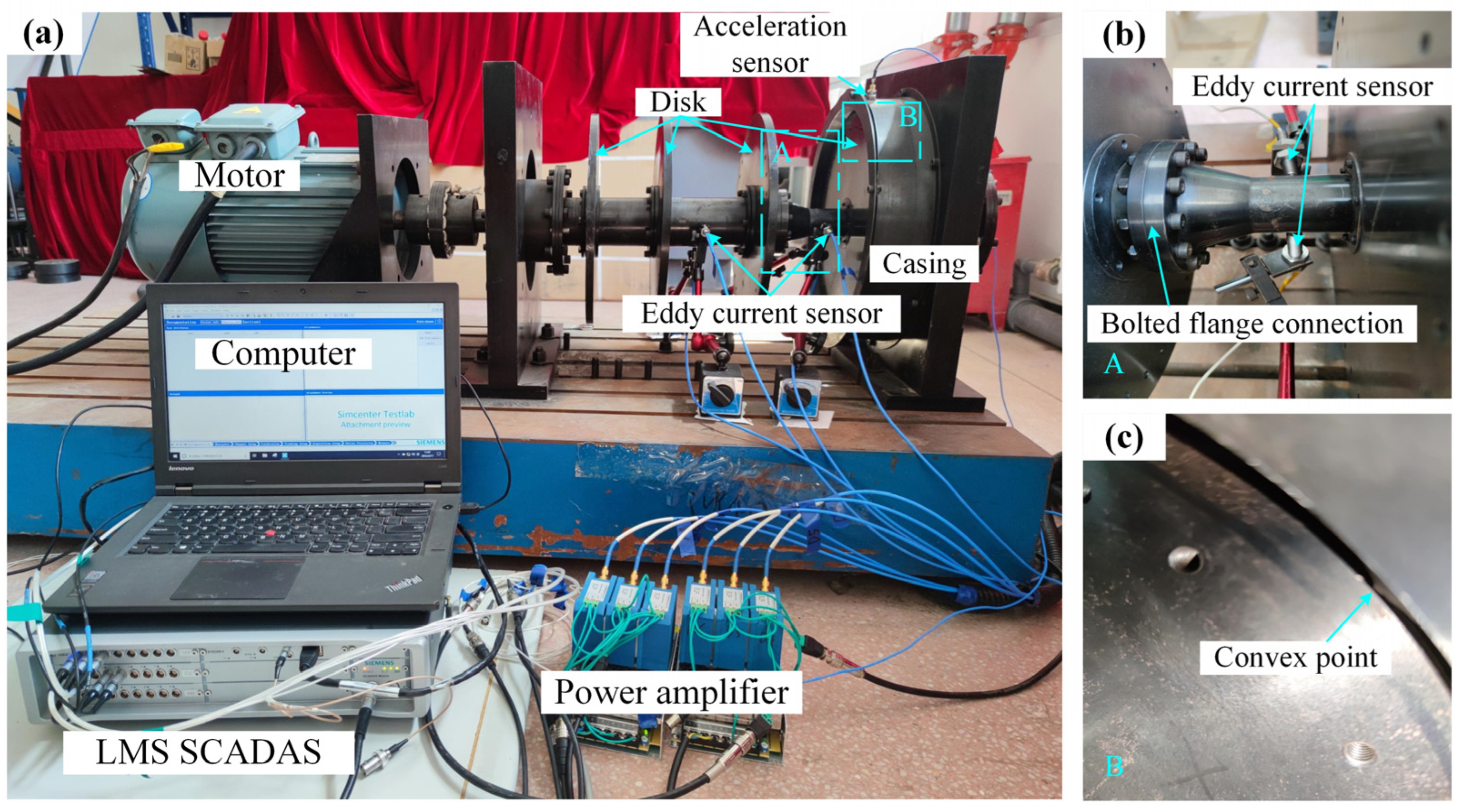
4. Experimental Study

To demonstrate the reliability of the numerical simulation findings for the rotor-casing coupling system, experimental research on the impact of fixed-point rubbing fault was carried out on the test rig shown in Figure 11. The test rig comprised a motor, bolted joint rotor-casing coupling system, power amplifier, LMS vibration signal acquisition system, etc. A motor was used to provide excitation to the rotor system, and the excitation frequency was controlled by a frequency converter. Moreover, the rubbing fault in the rotor-casing coupling system was simulated by the convex point shown in Figure 11c. The displacement signal was collected by the eddy current sensor, and the acceleration data was measured through the acceleration. All of the data were stored via the LMS SCADAS system, which was further analyzed by MATLAB software. In order to verify the outcomes of the numerical simulation, the system’s vertical responses, spectra, shaft orbit, and acceleration of the casing were obtained using the vibration displacement signal collection.
Experiments were conducted for two situations to explore the vibration characteristics of the coupled rotor system: one without rotor-casing rubbing fault and one with rubbing fault. Figure 12 shows the vertical vibration response, spectra, shaft orbits of the rotor system, and acceleration of the casing at ω = 1800 rev/min. The red circle shown in the shaft orbit diagram is the rubbing boundary, which is determined by using the diameters of the casing and disk. As depicted in Figure 12a,b, when the rotor system has a rotor-casing rubbing fault, the amplitude of the harmonic 2fr is clearly increased. Additionally, the rotor-casing rubbing fault causes a nonlinear impact effect that considerably increases the casing acceleration. These experimental results support the simulated results presented in Section 3.
The vertical vibration response, spectra, shaft orbits, and acceleration of the casing at ω = 2100 rev/min with and without rubbing fault are compiled and shown in Figure 13, which is used to further illustrate the impact of the rotor-casing rubbing fault on the coupling system. It can also be found that the amplitude of the harmonic 2fr and casing acceleration are significantly increased under the rubbing condition, which is agreement with the simulation results and previous experimental results. Therefore, an identifiable feature for the assessment of the aggravation of rotor-casing rubbing is the increase in the amplitude of 2fr and casing acceleration.

5. Conclusions

In this work, the vibration performance of a rotor-casing coupling system with a bolted flange connection and the effect of a rotor-casing rubbing fault on the nonlinear vibration performance of the coupling system were investigated. Firstly, the dynamic equations of the coupling system were established using the lumped mass modeling method, which considered the radial stiffness of a bolted flange structure with a spigot, squirrel cage with ball bearing, and rotor-casing coupling vibration. Then, to present the rotor-casing rubbing fault, an analytical model of nonlinear impact forces that considered the contact and vibration responses of the rotor and casing was developed. Moreover, the evolution of the motion state of the rotor-casing coupling system was deeply explored, both with and without rotor-casing rubbing faults, using the data, which included a bifurcation diagram, spectrum plot, and greatest Lyapunov exponents. The effect of rotor-casing rubbing faults on the system motion state was explored by comparing the above data under these two situations. Finally, the accuracy of the numerical simulation findings was confirmed by the comparison of the experimental and numerical simulation results. The following are the conclusions to the detailed typical characteristics of the coupling system and fixed-point rubbing:
  • The coupling system produces rich forms of motion, which are described as changing from quasi-periodic motion to 1T-periodic motion, quasi-periodic motion, 1T-periodic motion, 2T-periodic motion, and quasi-periodic motion. The rubbing fault significantly affects the state of the system’s motion; for example, weakening the periodic motion to a certain extent or expanding the rotational speed range of the quasi-periodic motion would reduce the system stability.
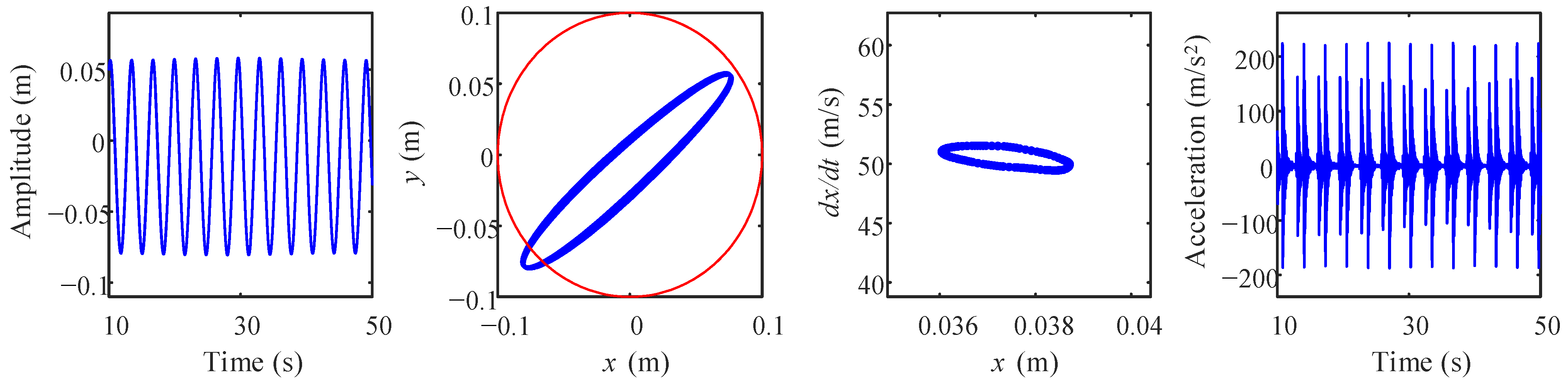
  • When the rubbing fault occurs, the amplitudes of the harmonic 2fr significantly increase, which is attributed to the additional nonlinear effect introduced by the impact forces acting on the rotor system. Moreover, the maximum value of the casing acceleration is also increased in the case with rotor-casing rubbing fault; for example, the maximum value of casing acceleration at 9480 rev/min increases from about 25 m/s2 to about 210 m/s2 under the rubbing fault. The above phenomenon can be considered as the most distinguishable characteristic for diagnosing the aggravation of rubbing fault in the rotor-casing coupling system.
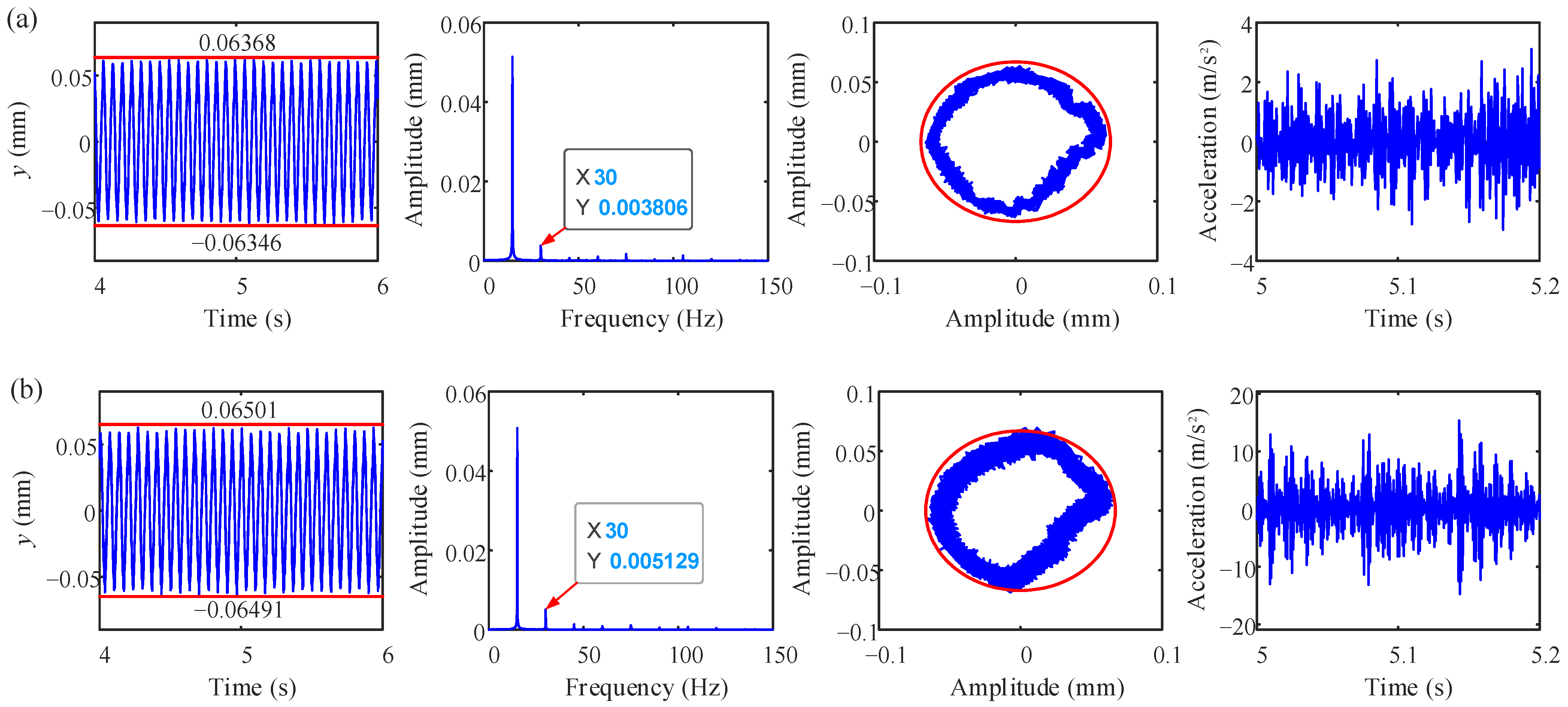
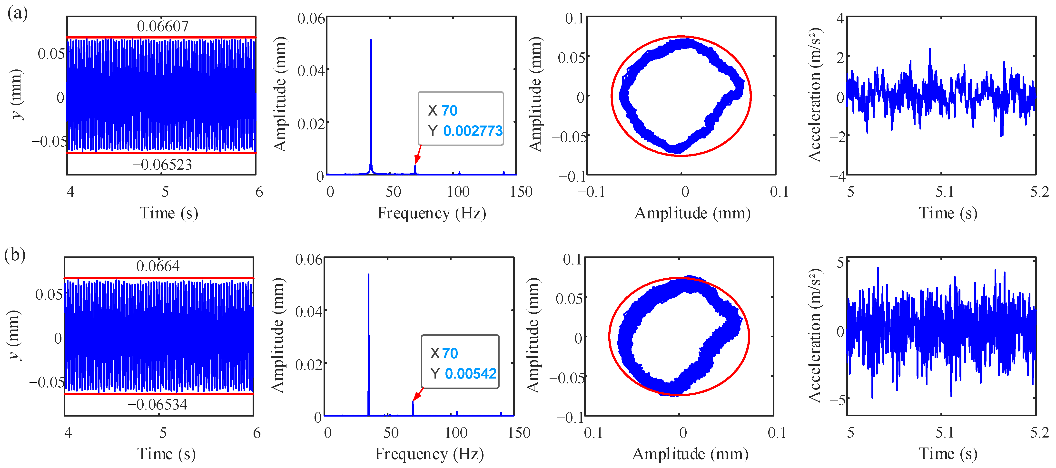
  • The experiments were conducted for four cases (with and without rubbing fault at ω = 1800 rev/min and ω = 2100 rev/min); the results show that the amplitudes of the harmonic 2fr and casing acceleration are obviously increased, which agree with the simulation results.
In this paper, the dynamic properties of rotor-casing coupling with rubbing fault were deeply explored. However, in actual operation, the rubbing fault of the rotor system would lead to abnormal vibration behavior, which would cause other faults to occur. Therefore, the dynamic properties of the rotor system with a multi-fault and the design of a suitable experiment to verify the numerical results will be considered in a future work.

Author Contributions

C.W.: Software, writing—original draft, and funding acquisition; Z.Z.: formal analysis and investigation; T.L.: conceptualization, funding acquisition, and project administration; L.J.: data curation and writing—review and editing; Y.L.: supervision, writing—review, methodology, and validation. All authors have read and agreed to the published version of the manuscript.

Funding

This research was supported by the Guangxi Natural Science Foundation under Grant No. 2022GXNSFBA035488, the Middle-aged and Young Teachers’ Basic Ability Promotion Project of Guangxi, China under Grant No. 2023KY0362, Science and Technology Project of Guangxi under Grant No. GK AD22080042, and Doctoral foundation of Guangxi University of Science and Technology under Grant No. XKB 21Z64.

Institutional Review Board Statement

Not applicable.

Data Availability Statement

Data will be made available on reasonable request.

Acknowledgments

Z.Z., C.W., T.L., and L.J. acknowledge the financial support of Guangxi University of Science and Technology, China.

Conflicts of Interest

The authors declare no conflict of interest, including specific financial interests and relationships relevant to the subject of this paper.

Appendix A

The expression of the matrix K is shown as below:
K = k 1 k 1 0 0 0 0 0 0 0 0 0 0 0 0 0 k 1 k 1 + k 2 + k b k b k 2 0 0 0 0 0 0 0 0 0 0 0 0 k b k b + k s 0 0 0 0 0 0 0 0 0 0 0 0 0 k 2 0 k 2 + k 3 k 3 0 0 0 0 0 0 0 0 0 0 0 0 0 k 3 k 3 + k 4 k 4 0 0 0 0 0 0 0 0 0 0 0 0 0 k 4 k 4 + k 5 k 5 0 0 0 0 0 0 0 0 0 0 0 0 0 k 5 k 5 + k 6 k 6 0 0 0 0 0 0 0 0 0 0 0 0 0 k 6 k 6 + k f k f 0 0 0 0 0 0 0 0 0 0 0 0 0 k f k f + k 7 k 7 0 0 0 0 0 0 0 0 0 0 0 0 0 k 7 k 7 + k 8 k 8 0 0 0 0 0 0 0 0 0 0 0 0 0 k 8 k 8 + k 9 k 9 0 0 0 0 0 0 0 0 0 0 0 0 0 k 9 k 9 + k 10 k 10 0 0 0 0 0 0 0 0 0 0 0 0 0 k 10 k 10 + k b k b 0 0 0 0 0 0 0 0 0 0 0 0 0 k b k b + k c + k s k c 0 0 0 0 0 0 0 0 0 0 0 0 0 k c k c
where the elements ki (i = 1, 2, 3, …, 9) can be calculated by [43]:
k i = 3 E I l i ( i = 1 , 6 , 7 , 10 ) k j = 12 E I l j ( j = 2 , 3 , 4 , 5 , 8 , 9 )
where EI represents the flexural rigidity of the shaft segment.
The expression of the matrix C is shown as below:
C = c 1 c 1 0 0 0 0 0 0 0 0 0 0 0 0 0 c 1 c 1 + c 2 + c b c b c 2 0 0 0 0 0 0 0 0 0 0 0 0 c b c b + c s 0 0 0 0 0 0 0 0 0 0 0 0 0 c 2 0 c 2 + c 3 c 3 0 0 0 0 0 0 0 0 0 0 0 0 0 c 3 c 3 + c 4 c 4 0 0 0 0 0 0 0 0 0 0 0 0 0 c 4 c 4 + c 5 c 5 0 0 0 0 0 0 0 0 0 0 0 0 0 c 5 c 5 + c 6 c 6 0 0 0 0 0 0 0 0 0 0 0 0 0 c 6 c 6 + c f c f 0 0 0 0 0 0 0 0 0 0 0 0 0 c f c f + c 7 c 7 0 0 0 0 0 0 0 0 0 0 0 0 0 c 7 c 7 + c 8 c 8 0 0 0 0 0 0 0 0 0 0 0 0 0 c 8 c 8 + c 9 c 9 0 0 0 0 0 0 0 0 0 0 0 0 0 c 9 c 9 + c 10 c 10 0 0 0 0 0 0 0 0 0 0 0 0 0 c 10 c 10 + c b c b 0 0 0 0 0 0 0 0 0 0 0 0 0 c b c b + c c + c s c c 0 0 0 0 0 0 0 0 0 0 0 0 0 c c c c

References

  1. Srivastava, A.K.; Tiwari, M.; Singh, A. Identification of rotor-stator rub and dependence of dry whip boundary on rotor parameters. Mech. Syst. Signal Process. 2021, 159, 107845. [Google Scholar] [CrossRef]
  2. Jiang, M.; Zheng, Z.; Xie, Y.; Zhang, D. Local Sensitivity Analysis of Steady-State Response of Rotors with Rub-Impact to Parameters of Rubbing Interfaces. Appl. Sci. 2021, 11, 1307. [Google Scholar] [CrossRef]
  3. Koten, H. Recent Researches in Engineering Sciences, 1st ed.; Livre de Lyon: Lyon, France, 2021. [Google Scholar]
  4. Jamia, N.; Jalali, H.; Taghipour, J.; Friswell, M.; Khodaparast, H.H. An equivalent model of a nonlinear bolted flange joint. Mech. Syst. Signal Process. 2020, 153, 107507. [Google Scholar] [CrossRef]
  5. Li, Y.; Luo, Z.; Liu, J.; Ma, H.; Yang, D. Dynamic modeling and stability analysis of a rotor-bearing system with bolted-disk joint. Mech. Syst. Signal Process. 2021, 158, 107778. [Google Scholar] [CrossRef]
  6. Li, Y.; Luo, Z.; Wang, J.; Ma, H.; Yang, D. Numerical and experimental analysis of the effect of eccentric phase difference in a rotor-bearing system with bolted-disk joint. Nonlinear Dyn. 2021, 105, 2105–2132. [Google Scholar] [CrossRef]
  7. Pan, W.; Li, X.; Ling, L.; Qu, H. Dynamic modeling and response analysis of rub-impact rotor system with squeeze film damper under maneuvering load. Appl. Math. Model. 2023, 114, 544–582. [Google Scholar] [CrossRef]
  8. Behzad, M.; Alvandi, M. Unbalance-induced rub between rotor and compliant-segmented stator. J. Sound Vib. 2018, 429, 96–129. [Google Scholar] [CrossRef]
  9. Behzad, M.; Alvandi, M. Friction-induced backward rub of rotors in non-annular clearances: Experimental observations and numerical analysis. Tribol. Int. 2020, 152, 106430. [Google Scholar] [CrossRef]
  10. Briend, Y.; Chatelet, E.; Dufour, R.; Andrianoely, M.-A.; Legrand, F.; Sousa, M.S.; Steffen, V.; Baudin, S. Dry-whip phenomenon in on-board rotordynamics: Modeling and experimentation. J. Sound Vib. 2021, 513, 116398. [Google Scholar] [CrossRef]
  11. Zhang, J.; Zhang, L.; Ma, Z.; Wang, X.; Wu, Q.; Fan, Z. Coupled bending-torsional vibration analysis for rotor-bearing system with rub-impact of hydraulic generating set under both dynamic and static eccentric electromagnetic excitation. Chaos Solitons Fractals 2021, 147, 110960. [Google Scholar] [CrossRef]
  12. Gao, T.; Cao, S.; Hou, L.; Hou, Y. An experimental study on the nonlinear vibration phenomenon of a rotor system subjected to barrel roll flight and coupled rub-impact faults. Measurement 2019, 153, 107406. [Google Scholar] [CrossRef]
  13. Kandil, A. Investigation of the whirling motion and rub/impact occurrence in a 16-pole rotor active magnetic bearings system with constant stiffness. Nonlinear Dyn. 2020, 102, 2247–2265. [Google Scholar] [CrossRef]
  14. Yang, Y.; Cao, D.; Yu, T.; Wang, D.; Li, C. Prediction of dynamic characteristics of a dual-rotor system with fixed point rubbing—Theoretical analysis and experimental study. Int. J. Mech. Sci. 2016, 115–116, 253–261. [Google Scholar] [CrossRef]
  15. Yang, Y.; Yang, Y.; Cao, D.; Chen, G.; Jin, Y. Response evaluation of imbalance-rub-pedestal looseness coupling fault on a geometrically nonlinear rotor system. Mech. Syst. Signal Process. 2018, 118, 423–442. [Google Scholar] [CrossRef]
  16. Zhang, Y.; Xiang, L.; Hu, A.; Chen, K. Nonlinear dynamic response on multi-fault rod fastening rotor with variable parameters. Appl. Math. Model. 2023, 114, 147–161. [Google Scholar] [CrossRef]
  17. Mokhtar, A.; Darpe, A.K.; Gupta, K. Investigations of Rubbing Phenomenon during Coast-up Operation of a Cryogenic Engine Turbopump. J. Vib. Eng. Technol. 2019, 8, 737–749. [Google Scholar] [CrossRef]
  18. Zeng, J.; Ma, H.; Yu, K.; Guo, X.; Wen, B. Rubbing response comparisons between single blade and flexible ring using different rubbing force models. Int. J. Mech. Sci. 2019, 164, 105164. [Google Scholar] [CrossRef]
  19. Kang, Y.; Cao, S.; Hou, Y.; Chen, N.; Li, B. Dynamics research on the rubbing process and rubbing forms of rotor-blade-casing systems. Int. J. Non-Linear Mech. 2022, 147, 104242. [Google Scholar] [CrossRef]
  20. Wang, N.; Jiang, D.; Xu, H. Effects of Rub-Impact on Vibration Response of a Dual-Rotor System-Theoretical and Experimental Investigation. Exp. Tech. 2019, 44, 299–311. [Google Scholar] [CrossRef]
  21. Liu, X.; Liu, Y.; Wang, S.; Yan, H.; Liao, P. Bifurcation analysis of a magnetically supported rigid rotor in auxiliary bearings. Chaos Solitons Fractals 2018, 118, 328–336. [Google Scholar] [CrossRef]
  22. Prabith, K.; Krishna, I.R.P. The numerical modeling of rotor–stator rubbing in rotating machinery: A comprehensive review. Nonlinear Dyn. 2020, 101, 1317–1363. [Google Scholar] [CrossRef]
  23. Zhang, Y.; Xiang, L.; Su, H.; Hu, A.; Yang, X. Dynamic analysis of composite rod fastening rotor system considering multiple parameter influence. Appl. Math. Model. 2022, 105, 615–630. [Google Scholar] [CrossRef]
  24. Hong, J.; Yang, Z.; Wang, Y.; Cheng, R.; Ma, Y. Combination resonances of rotor systems with asymmetric residual preloads in bolted joints. Mech. Syst. Signal Process. 2023, 183, 109626. [Google Scholar] [CrossRef]
  25. Li, J.; Li, Y.; Zhang, F.; Feng, Y. Nonlinear Analysis of Rod Fastened Rotor under Nonuniform Contact Stiffness. Shock Vib. 2020, 2020, 8851996. [Google Scholar] [CrossRef]
  26. Li, J.; Yang, Z.; Ren, Q.; Mo, G.; Zhong, W.; Feng, Y.; Li, G. Study on the bistable vibration behaviour of a rod-fastened rotor-bearing system. Nonlinear Dyn. 2022, 109, 609–629. [Google Scholar] [CrossRef]
  27. Qin, Z.Y.; Han, Q.K.; Chu, F.L. Analytical model of bolted disk–drum joints and its application to dynamic analysis of jointed rotor. Proc. Inst. Mech. Eng. Part C J. Mech. Eng. Sci. 2013, 228, 646–663. [Google Scholar] [CrossRef]
  28. Qin, Z.; Han, Q.; Chu, F. Bolt loosening at rotating joint interface and its influence on rotor dynamics. Eng. Fail. Anal. 2016, 59, 456–466. [Google Scholar] [CrossRef]
  29. Li, C.; Qiao, R.; Tang, Q.; Miao, X. Investigation on the vibration and interface state of a thin-walled cylindrical shell with bolted joints considering its bilinear stiffness. Appl. Acoust. 2020, 172, 107580. [Google Scholar] [CrossRef]
  30. Wu, X.; Jiao, Y.; Chen, Z.; Ma, W. Establishment of a contact stiffness matrix and its effect on the dynamic behavior of rod-fastening rotor bearing system. Arch. Appl. Mech. 2021, 91, 3247–3271. [Google Scholar] [CrossRef]
  31. Wang, L.; Wang, A.; Jin, M.; Huang, Q.; Yin, Y. Nonlinear effects of induced unbalance in the rod fastening rotor-bearing system considering nonlinear contact. Arch. Appl. Mech. 2019, 90, 917–943. [Google Scholar] [CrossRef]
  32. Wang, L.; Wang, A.; Jin, M.; Yin, Y.; Heng, X.; Ma, P. Nonlinear dynamic response and stability of a rod fastening rotor with internal damping effect. Arch. Appl. Mech. 2021, 91, 3851–3867. [Google Scholar] [CrossRef]
  33. Mokhtar, A.; Darpe, A.K.; Gupta, K. Analysis of stator vibration response for the diagnosis of rub in a coupled rotor-stator system. Int. J. Mech. Sci. 2018, 144, 392–406. [Google Scholar] [CrossRef]
  34. Wang, N.; Liu, C.; Jiang, D.; Behdinan, K. Casing vibration response prediction of dual-rotor-blade-casing system with blade-casing rubbing. Mech. Syst. Signal Process. 2018, 118, 61–77. [Google Scholar] [CrossRef]
  35. Yang, Y.; Ouyang, H.; Yang, Y.; Cao, D.; Wang, K. Vibration analysis of a dual-rotor-bearing-double casing system with pedestal looseness and multi-stage turbine blade-casing rub. Mech. Syst. Signal Process. 2020, 143, 106845. [Google Scholar] [CrossRef]
  36. Li, Y.; Wen, C.; Luo, Z.; Jin, L. Vibration analysis of a multi-disk bolted joint rotor-bearing system subjected to fixed-point rubbing fault. Int. J. Non-Linear Mech. 2022, 146, 104165. [Google Scholar] [CrossRef]
  37. Li, Y.; Wen, C.; Luo, Z.; Jin, L. Bifurcation studies of a bolted-joint rotor system subjected to fixed-point rubbing fault. Nonlinear Dyn. 2022, 110, 3045–3073. [Google Scholar] [CrossRef]
  38. Chipato, E.T.; Shaw, A.D.; Friswell, M. Nonlinear rotordynamics of a MDOF rotor–stator contact system subjected to frictional and gravitational effects. Mech. Syst. Signal Process. 2021, 159, 107776. [Google Scholar] [CrossRef]
  39. Wen, C.; Li, Y.; Jin, L.; Yang, D. Bifurcation and Stability Analysis of a Bolted Joint Rotor System Contains Multi-Discs Subjected to Rub-Impact Effect. Processes 2022, 10, 1763. [Google Scholar] [CrossRef]
  40. Yu, P.; Wang, C.; Hou, L.; Chen, G. Dynamic characteristics of an aeroengine dual-rotor system with inter-shaft rub-impact. Mech. Syst. Signal Process. 2021, 166, 108475. [Google Scholar] [CrossRef]
  41. Xiang, L.; Zhang, Y.; Hu, A.; Ye, F. Dynamic analysis and experiment investigation of a cracked dual-disc bearing-rotor system based on orbit morphological characteristics. Appl. Math. Model. 2019, 80, 17–32. [Google Scholar] [CrossRef]
  42. Cao, J.; Ma, C.; Jiang, Z.; Liu, S. Nonlinear dynamic analysis of fractional order rub-impact rotor system. Commun. Nonlinear Sci. Numer. Simul. 2011, 16, 1443–1463. [Google Scholar] [CrossRef]
  43. Gao, T.; Cao, S. Paroxysmal impulse vibration phenomena and mechanism of a dual–rotor system with an outer raceway defect of the inter-shaft bearing. Mech. Syst. Signal Process. 2021, 157, 107730. [Google Scholar] [CrossRef]
  44. Mir-Haidari, S.-E.; Behdinan, K. Nonlinear effects of bolted flange connections in aeroengine casing assemblies. Mech. Syst. Signal Process. 2021, 166, 108433. [Google Scholar] [CrossRef]
  45. Yu, P.; Li, L.; Chen, G.; Yang, M. Dynamic modelling and vibration characteristics analysis for the bolted joint with spigot in the rotor system. Appl. Math. Model. 2021, 94, 306–331. [Google Scholar] [CrossRef]
  46. Haslam, A.H.; Schwingshackl, C.W.; Rix, A.I.J. A parametric study of an unbalanced Jeffcott rotor supported by a rolling-element bearing. Nonlinear Dyn. 2020, 99, 2571–2604. [Google Scholar] [CrossRef]
  47. Jin, Y.; Liu, Z.; Yang, Y.; Li, F.; Chen, Y. Nonlinear vibrations of a dual-rotor-bearing-coupling misalignment system with blade-casing rubbing. J. Sound Vib. 2021, 497, 115948. [Google Scholar] [CrossRef]
  48. Zhang, X.; Yang, Y.; Ma, H.; Shi, M.; Wang, P. A novel diagnosis indicator for rub-impact of rotor system via energy method. Mech. Syst. Signal Process. 2023, 185, 109825. [Google Scholar] [CrossRef]
  49. Zhao, Y.; Zhu, Y.-P.; Lin, J.; Han, Q.; Liu, Y. Analysis of nonlinear vibrations and health assessment of a bearing-rotor with rub-impact based on a data-driven approach. J. Sound Vib. 2022, 534, 117068. [Google Scholar] [CrossRef]
Figure 1. The application field of the proposed research: (a) the rubbing fault of a certain type of aero-engine, (b) a certain type of marine gas turbine, and (c) a certain type of wind turbine.
Processes 11 01301 g001
Figure 2. Schematic diagram of the bolted joint rotor-casing coupling system. (a) The coupled rotor-casing system, (b) bolted flange connection, and (c) squirrel structure with bearing.
Processes 11 01301 g002
Figure 3. Schematic diagram of the rotor-casing coupling system under rubbing fault.
Processes 11 01301 g003
Figure 4. Sketch of each region in the bolted joint structure and modeling parameters of the bolted joint with a spigot. (a) Divided regions of the bolted joint; (b) physical parameters of the bolted joint.
Processes 11 01301 g004
Figure 5. Action zone of the radial stiffness of each region in the bolted joint structure.
Processes 11 01301 g005
Figure 6. The block diagram of the solving process of the governing equation.
Processes 11 01301 g006
Figure 7. Bifurcation diagram, largest Lyapunov exponents, and three-dimensional spectrum of disk 4 at ω = [5400 22,800] rev/min. (a) Bifurcation diagram; (b) largest Lyapunov exponents; (c) three-dimensional spectrum.
Processes 11 01301 g007
Figure 8. Time–domain waveform, axis orbit, Poincaré map, and acceleration of the casing at (a) 5520 rev/min, (b) 9480 rev/min, (c) 11,760 rev/min, (d) 20,280 rev/min, and (e) 21,000 rev/min.
Processes 11 01301 g008
Figure 9. Bifurcation diagram, largest Lyapunov exponents, maximum amplitude with rotor-casing clearance, and three-dimensional spectrum at disk 4 with rubbing fault. (a) Bifurcation diagram; (b) largest Lyapunov exponents; (c) maximum amplitude with rotor-casing clearance; (d) three-dimensional spectrum.
Processes 11 01301 g009
Figure 10. Time–domain waveform, axis orbit, Poincaré map, and acceleration of casing at 9480 rev/min while the rotor-casing rubbing force is acting on disk 4.
Processes 11 01301 g010
Figure 11. Experimental setup. (a) Rotor-casing coupling system with data acquisition equipment; (b) bolted flange connection; (c) convex point in the coupled system.
Processes 11 01301 g011
Figure 12. Vertical vibration responses of the rotor system, spectra, shaft orbit, and acceleration of the casing at ω = 1800 rev/min (a) without rotor–stator rubbing fault and (b) with rotor–stator rubbing fault.
Processes 11 01301 g012
Figure 13. Vertical vibration responses of the rotor system, spectra, shaft orbit, and acceleration of the casing at ω = 2100 rev/min (a) without rotor–stator rubbing fault and (b) with rotor–stator rubbing fault.
Processes 11 01301 g013
Table 1. Specific system parameters of the rotor system.
Physical ParametersValuesPhysical ParametersValues
Length of the shaft section l1 (m)0.08Radius of the shaft section r1 (m)0.04
Length of the shaft section l2 (m)0.08Radius of the shaft section r2 (m)0.04
Length of the shaft section l3 (m)0.05Radius of the shaft section r3 (m)0.08
Length of the shaft section l4 (m)0.11Radius of the shaft section r4 (m)0.08
Length of the shaft section l5 (m)0.14Radius of the shaft section r5 (m)0.08
Length of the shaft section l6 (m)0.07Radius of the shaft section r6 (m)0.08
Length of the shaft section l7 (m)0.07Radius of the shaft section r7 (m)0.07
Length of the shaft section l8 (m)0.08Radius of the shaft section r8 (m)0.05
Length of the shaft section l9 (m)0.07Radius of the shaft section r9 (m)0.05
Length of the shaft section l10 (m)0.09Radius of the shaft section r10 (m)0.04
Stiffness of squirrel ks (N/m)1 × 108Coupling stiffness kc (N/m)1 × 103
Mass of disk 1, 2, 3 (kg)17.16Eccentricity of disk 1,2,3,4 (m)0.05 × 10⁻³
Mass of disk 4 (kg)16.4Outer radius of the spigot ro (m)0.05
Friction coefficient at rubbing position η0.1Radius of the bolt head rb (m)0.012
Width of each region of bolted flange W (m)0.06Radius of spigot R (m)0.06
Thicknesses of upper flange T1 (m)0.01Poisson ratio of upper flange v1 0.28
Thicknesses of lower flange T2 (m)0.01Poisson ratio of lower flange v20.28
Elastic modulus of upper flange E1 (Pa) 1.96 × 10¹¹Inner radius of the spigot ri (m)0.06
Elastic modulus of lower flange E2 (Pa)1.96 × 10¹¹Clearance between rotor and casing r0 (m)1 × 10⁻⁴
Table 2. Structural parameters of the ball bearings.
Radius of Outer
Race R (mm)
Radius of Inner
Race r (mm)
Numbers of
Ball Elements Nb
Contact Stiffness
k c (N/m3/2)
Bearing Clearance
r0 (µm)
63.940.1813.4 × 1095
Disclaimer/Publisher’s Note: The statements, opinions and data contained in all publications are solely those of the individual author(s) and contributor(s) and not of MDPI and/or the editor(s). MDPI and/or the editor(s) disclaim responsibility for any injury to people or property resulting from any ideas, methods, instructions or products referred to in the content.

