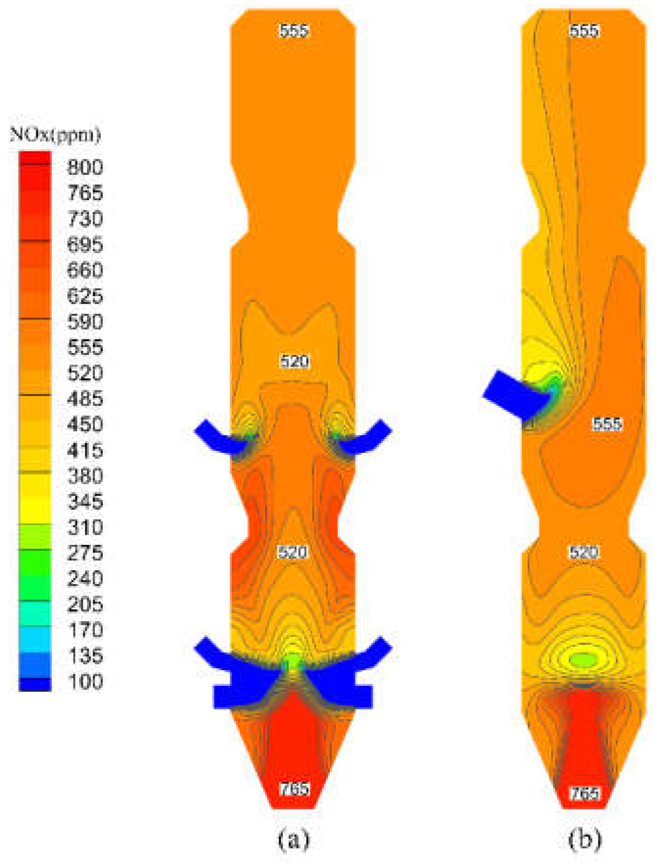
4.3.1. Analysis and Optimization of SNCR Process
The distribution of NO
x in the precalciner is shown in
Figure 7. The NO
x in the precalciner mainly comes from fuel NO
x from pulverized coal combustion and thermal NO
x from the rotary kiln. The NO
x concentration in the bottom area of the precalciner is approximately 750 ppm, where the NO
x is mainly thermal NO
x from the rotary kiln. As the flue gas rises, the inner diameter of the precalciner gradually expands, and due to the dilution of the tertiary air, the concentration of NO
x decreases rapidly, reaching a minimum of approximately 280 ppm near the tertiary air. Then, the concentration of NO
x in the main combustion area begins to rise rapidly because with the oxygen brought in by the tertiary air, the pulverized coal burns violently, thus producing a large amount of fuel NO
x. Then, the NO
x concentration started to decrease, because the air classification design of the precalciner made the pulverized coal burn incompletely and produced CO, which reduced part of the NO
x, and the air brought in by the upper tertiary air also diluted the NO
x concentration. After the flue gas reaches the middle column, CO and the incomplete combustion of pulverized coal particles are mixed with the upper tertiary air and continue to burn, and NO
x begins to increase, thus forming a locally high concentration area, the concentration in the local area is about 560 ppm. After leaving the burnout area, the NO
x concentration still increases slowly because of the continuous combustion of pulverized coal particles, but the growth rate gets slower and slower, and the NO
x concentration at the outlet is 531.33 ppm.
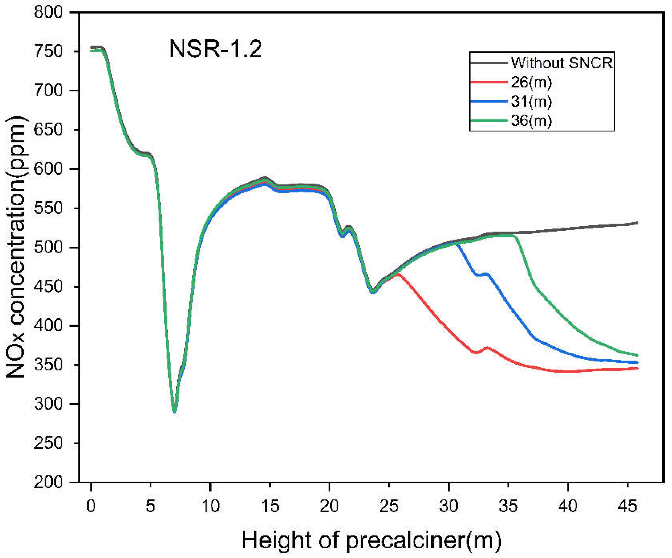
Figure 8 shows the variation of the average NO
x concentration along the height in the precalciner after SNCR denitrification with different reductant injection heights at an ammonia-to-nitrogen ratio (NSR) of 1.2. In accordance with the previous discussion, the area between the burnout area and the outlet (25–46 m) is the most favorable area for the mixing and reaction of the reductant and the flue gas due to its stable flow field, uniform temperature distribution, and compliance with SNCR requirements. Therefore, three different ammonia injection heights (26 m, 31 m, and 36 m) in this zone, with a variation gradient of 5 m, were selected for SNCR the denitrification simulation study. It can be seen from
Figure 8 that when the reductant is injected, the NO
x in the flue gas immediately starts the reduction reaction, leading to a sharp drop of the NO
x concentration in a very short time. This is mainly because, due to the high injecting velocity, the reductant can penetrate deeply into the flue gas and mix with the flue gas quickly, and then the reduction reaction occurs. After this, the remaining small amount of reductant continues to rise and react with the NO
x in the precalciner. However, at this time, the reductant can only mix and react with NO
x in a slow diffusion manner, so the decreasing trend of NO
x concentration begins to slow down. At the same time, there is a local increase in NO
x concentration when passing through the indentation area. It can be seen from the figure that the higher the height of the reductant injection, the faster the rate of NO
x reduction. This is mainly because the higher the height is, the closer it is to the precalciner outlet, where the flow and component fields are more stable, and the concentration of NO
x in the flue gas is also higher, which is more favorable to the reduction reaction. However, the simulation results show that the NO
x concentrations at the outlet of the precalciner for different ammonia injection heights are 345.84 ppm, 353.16 ppm, and 362.50 ppm, respectively, indicating that the NO
x concentration at the outlet increases with the increase of height. This is because the higher the height of the ammonia injection port, the shorter the time for the reduction reaction between the reductant and NO
x. Therefore, the reductant does not have enough time to mix and react with the remaining flue gas after reducing the NO
x in the flue gas near the ammonia injection port, thus reducing the total NO
x reduction rate. In addition, the shortened reaction time allows a large amount of reductant to be carried out of the precalciner by the gas flow before it is completely consumed. Moreover, the higher the injection height, the higher the NH
3 escape amount, reaching a maximum of 8.61 mg/m
3. With a larger NSR, there will be more unreacted reductant, resulting in more NH
3 escape. In general, the injection height of the reducing agent should be controlled within a certain range. Considering that the location of the reductant injection should avoid the indentation area and avoid the increase of ammonia escape caused by the short residence time of the reductant, the height of the reductant injection should be set within the range of 26–30 m of the precalciner.
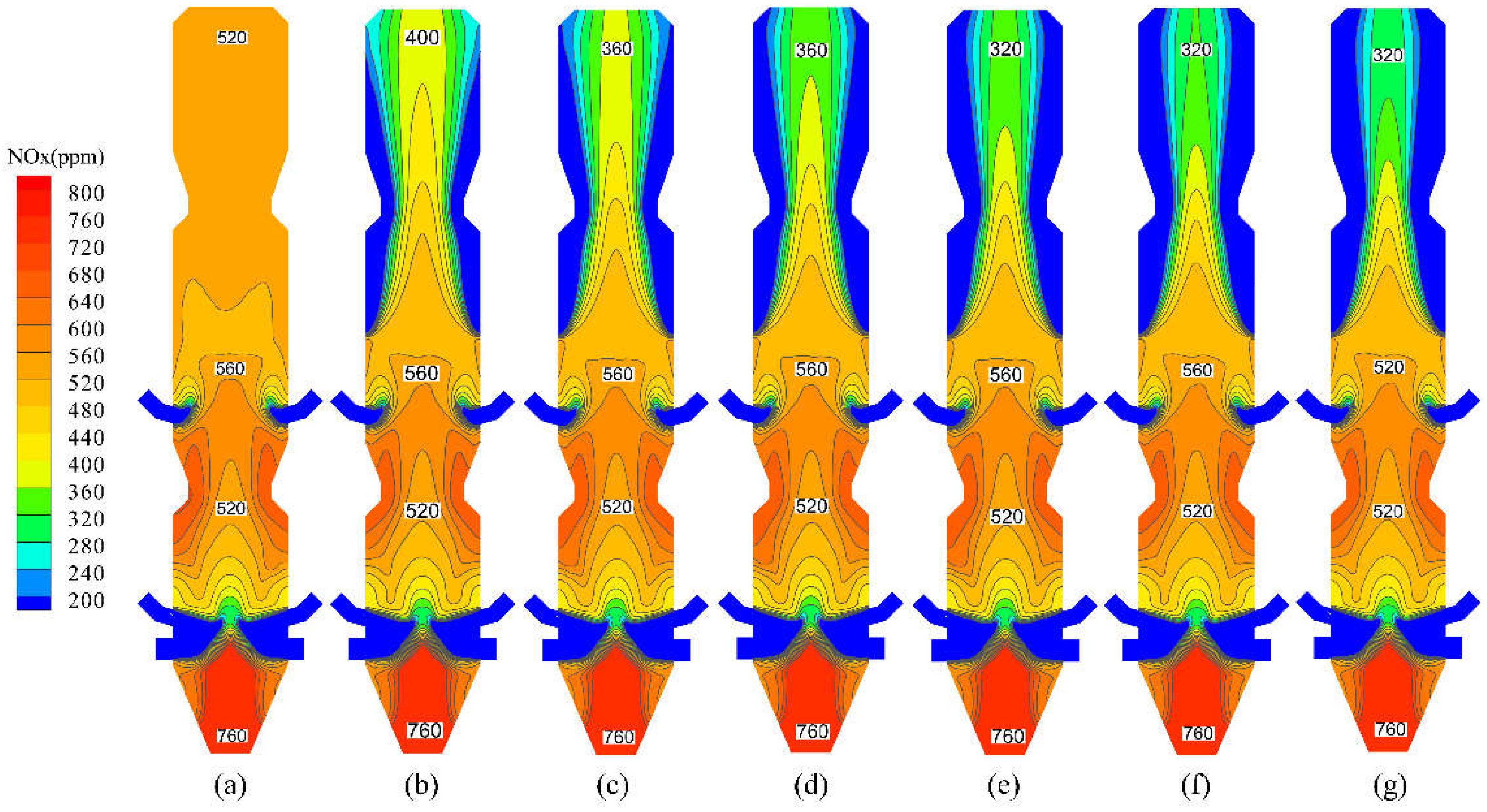
Figure 9 shows the distribution of NO
x in the precalciner at different reductant injection amounts. It can be seen from
Figure 9 that the reduction reaction with NO
x starts immediately after the reductant is injected symmetrically from both sides of the precalciner at the height of Z = 26 m, consuming NO
x in a large quantity in the area near the reductant injection port. At the same time, the concentration of NO
x in the upper column of the precalciner decreases due to the further mixing and reaction of the reductant with the flue gas.
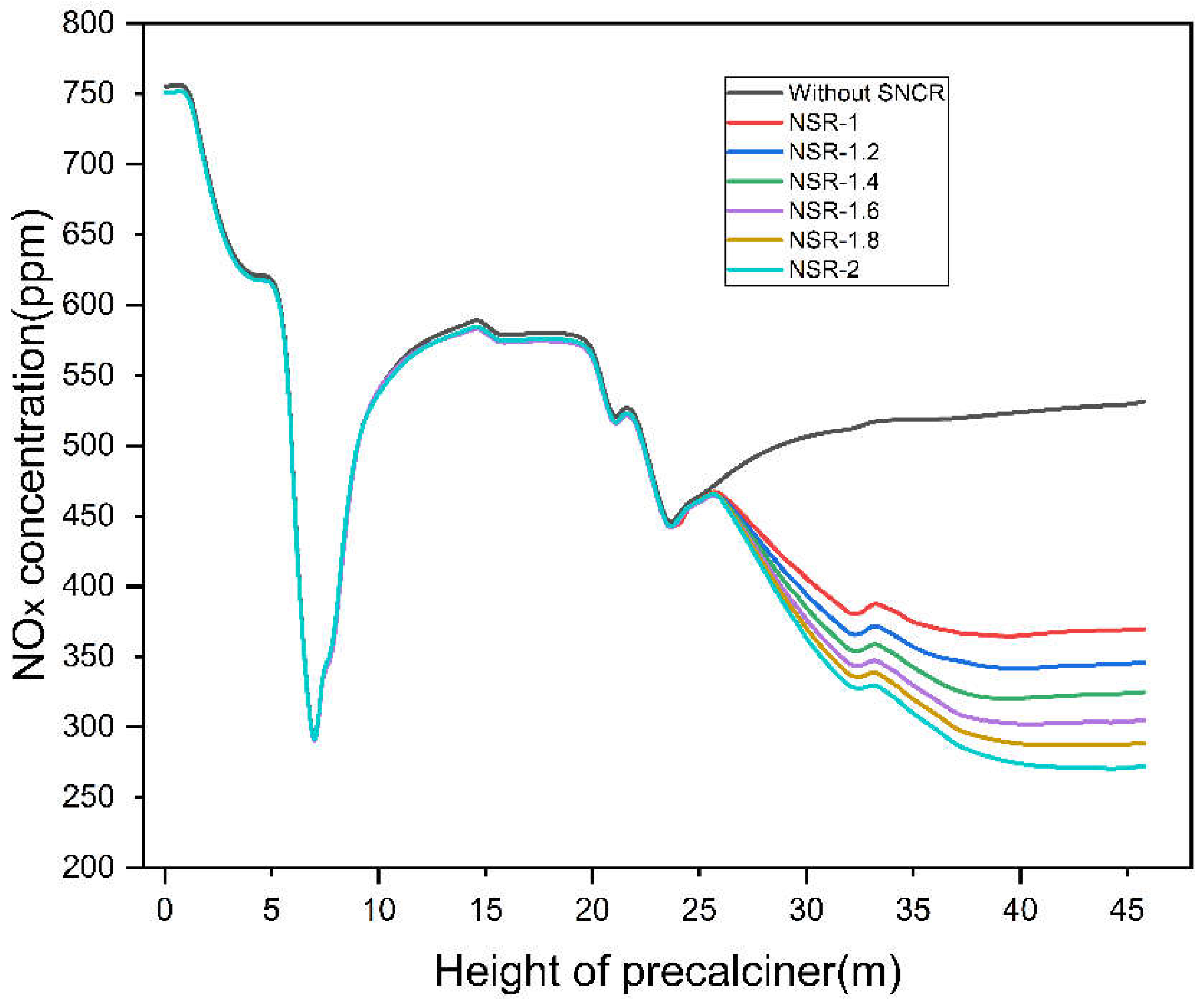
Figure 10 shows the variation of the average concentration of NO
x along the height in the precalciner at different reductant injection amounts. Notably, the figure reveals that the SNCR process is divided into two stages: the first stage is in the 26–37 m region of the precalciner, and the second stage in the region of 37–46 m. In the first stage, the reductant is injected with high initial velocity so that it can penetrate the flue gas and mix with more NO
x after injection. The concentration of the reductant near the nozzle is higher than required for the reduction reaction (except for the relatively lower concentration at the indentation), so this is a rapid stage for SNCR denitrification, which makes the NO
x concentration decrease rapidly. In fact, most of the NO
x is reduced in this stage. Meanwhile, it can be found that the larger the NSR is, the more the amount of injected reductant is, the faster the NO
x is reduced in this stage, and the more the total amount of NO
x is reduced. In the second stage, the mixing of the reductant and NO
x in this stage depends on the diffusion of the reductant. Due to the greatly reduced concentration of reductant owing to the rapid consumption in the previous stage, the reductant does not diffuse or mix with NO
x in time, i.e., the local reduction is stagnant. Therefore, the reduction reaction proceeds slowly in this stage. The larger the NSR, the higher the amount of reductant injection, the longer the denitrification duration of this stage, and the more NO
x is reduced. In general, the NO
x concentration at the outlet shows a positive correlation with the NSR in a stepwise manner. According to the simulated results, the NO
x concentrations at the outlet of the precalciner under different NSR are 370.11 ppm, 346.04 ppm, 325.94 ppm, 304.90 ppm, 288.03 ppm and 272.06 ppm, respectively; the calculated NO
x reduction rates of each group are 30.34%, 34.9%, 38.66%, 42.62%, 45.79% and 48.8%, respectively, all of which meet the NO
x emission standards. However, a larger NSR means more reductant is injected, and the ammonia escape is also larger. In addition, in other numerical simulation studies on SNCR denitrification in precalciner, it has been demonstrated that ammonia escape increases significantly when the NSR is too large [
8]. In particular, according to the simulation results, when the NSR are 1.8 and 2, the ammonia fugitive amounts are 10.11 mg/m
3 and 11.22 mg/m
3, respectively, and such a large amount of NH
3 escape can cause serious pollution problems. After considering the denitrification efficiency, cost, and NH
3 escape of SNCR, the NSR should be between 1 and 1.6 for SNCR denitrification.
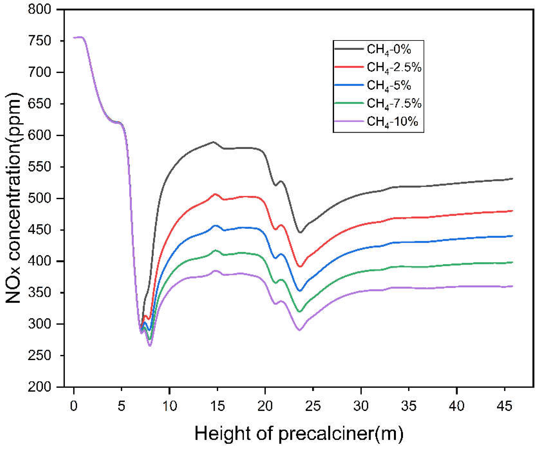
4.3.2. Analysis of Denitrification of Injected Natural Gas
Figure 11 shows the variation of NO
x concentration along the height in the precalciner with different injection amounts of natural gas.
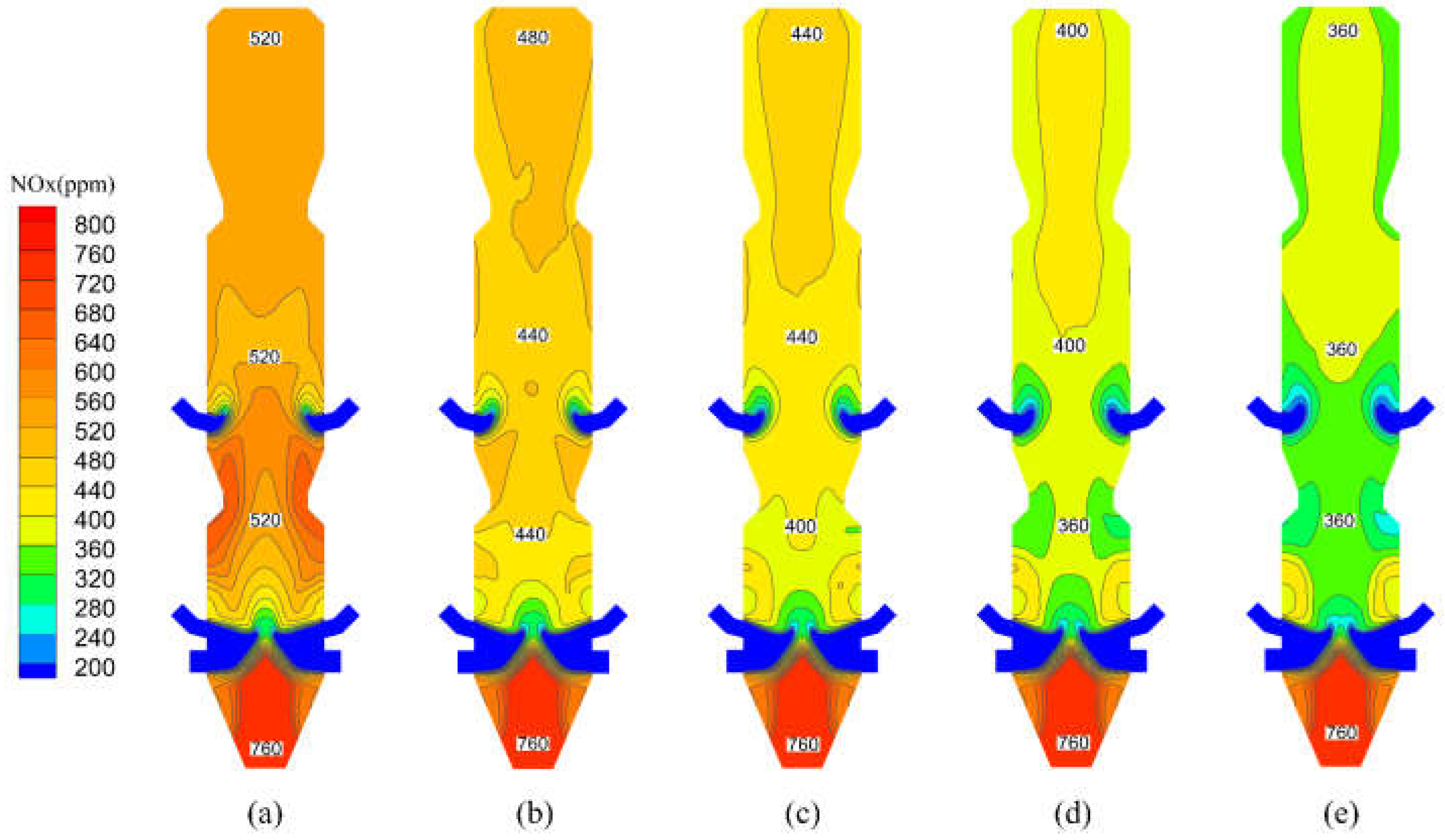
Figure 12 reveals the distribution of NO
x in the precalciner after natural gas injection. From these two figures, it can be observed that the natural gas injection reduces the NO
x generation in the precalciner, which leads to a decreased average NO
x concentration and more uniform NO
x distribution.
Figure 11 shows that the NO
x distribution in the area from the precalciner inlet to the tertiary air is not affected by the natural gas injection, and the changes of NO
x distribution are mainly concentrated in the area of 8–25 m. In the main combustion zone, the NO
x concentration decreases rapidly after the injection of natural gas, and the more natural gas is injected, the lower the concentration of NO
x is, and the more uniform the distribution of NO
x is. Correspondingly, in
Figure 12, the average NO
x concentration decreases significantly at the height of approximately 8 m in the precalciner, and the more natural gas is injected, the greater the decrease in concentration, which is due to the reduction reaction between the natural gas and NO
x immediately after the injection. In the area of 8–15 m, the NO
x concentration increases rapidly, because a large amount of fuel NO
x was generated by the mixed combustion of pulverized coal and the tertiary air, and the average NO
x concentration reaches the maximum at the height of 15 m. However, the injection of natural gas reduces the increasing speed of the NO
x concentration in this area, with the NO
x concentrations being approximately 510 ppm, 460 ppm, 410 ppm, and 380 ppm at the height of 15 m. As the amount of natural gas injected increases, the amount and rate of NO
x generation becomes lower. This phenomenon, besides the reason that natural gas has a reducing effect on NO
x, is also due to the rapid combustion of natural gas consuming a large amount of oxygen, which reduces the excess air coefficient in the main combustion zone. Under a low excess air coefficient, the amount of CO produced during the combustion of pulverized coal in the main combustion zone increases, and as a reductant, CO reacts with NO
x, which reduces the concentration of NO
x. At the same time, H
2O, as a main product of CH
4 combustion, can be converted to H
2 at high temperatures, which can also reduce NO
x [
37]. In general, the reduction rate of NO
x in the precalciner is positively related to the amount of natural gas injected: the higher the amount of injected natural gas, the higher the NO
x reduction efficiency. According to the simulation results, the NO
x concentrations at the precalciner outlet after natural gas injection are 480.515 ppm, 440.583 ppm, 398.539 ppm, and 360.501 ppm, respectively, while the NO
x concentration at the precalciner outlet without denitrification is 531.33 ppm. Based on the simulation results, it is calculated that the NO
x reduction rates in the precalciner with different natural gas injection amounts are 9.56%, 17.08%, 24.99%, and 32.15% respectively, which indicates that the natural gas injection can effectively reduce the NO
x emission from the precalciner.
4.3.3. Analysis of Combined Denitrification
In addition to the effect of natural gas on the generation and reduction of NO
x in the precalciner, this study also investigated the efficiency of natural gas reburning denitrification when applied in combination with SNCR technology.
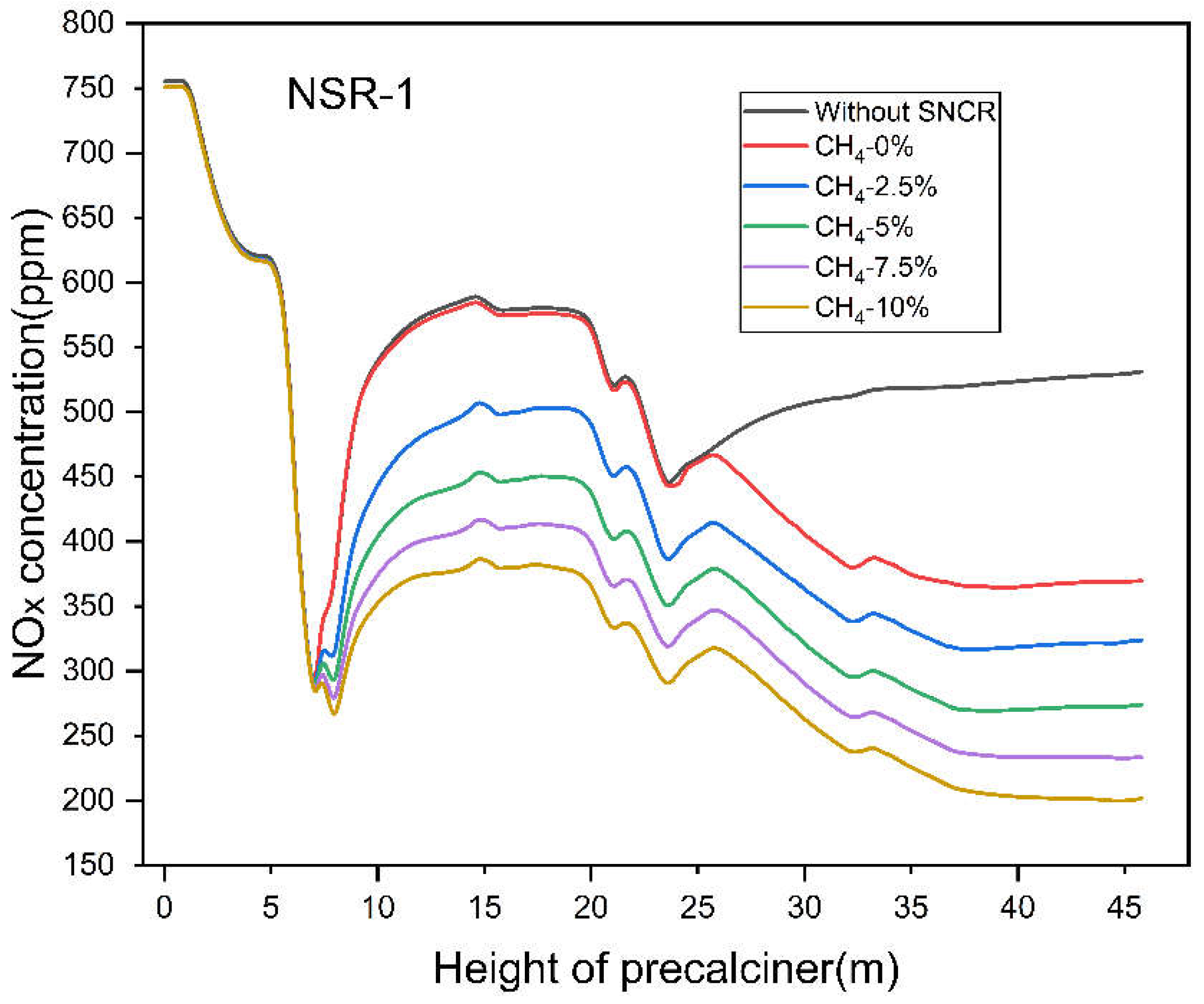
Figure 13 shows the variation of NO
x concentration along the height in the precalciner for combined denitrification. The NSR of SNCR for combined denitrification is 1, the height of reductant injection is 26 m, and the natural gas injection amounts are 2.5%, 5%, 7.5%, and 10%, respectively.
From
Figure 13, it can be seen that the trend of NO
x concentration in the area between 8 and 25 m in the precalciner after combined denitrification is very close to that in
Figure 12. The area after 25 m is the SNCR denitrification area, and the NO
x concentration starts to decrease rapidly from 25 m onward. Moreover, the higher the natural gas injection, the faster the NO
x concentration decreases. Even in the diffusive reduction phase, where NO
x reduction is weak, the rate of NO
x decline becomes faster. After comparing
Figure 13 with
Figure 12, it can be seen that natural gas reburning denitrification has a facilitating effect on SNCR technology. It can also be seen that the efficiency of combined denitrification is higher than the efficiency of natural gas reburning denitrification alone. According to the simulation results, the NO
x concentrations at the outlet after combined denitrification are 323.87 ppm, 273.96 ppm, 233.27 ppm, and 201.97 ppm, respectively. The calculated NO
x reduction rates for each group are 39.05%, 48.44%, 56.1%, and 61.98%, respectively, which shows that the combined denitrification technology has a good denitrification effect. In contrast, the NO
x reduction rate of SNCR denitrification is only 30.34%, much less than that of combined denitrification.
In summary, the denitrification effect of the combined denitrification technology is better than reburning denitrification alone or SNCR denitrification alone. In addition, the NOx reduction rate of SNCR denitrification alone at a NSR of 2 is 48.8%, while the NOx reduction rate of combined denitrification technology at a NSR of 1 with 5% natural gas injection is 48.44%, indicating that combined denitrification can significantly reduce the amount of reductant at a similar NOx reduction rate. According to the results of the above study, the combined denitrification technology, if put into practice, can save 50% of the urea-reductant dosage with the same denitrification rate, which requires an additional 5% of the pulverized coal mass of LNG. At the same time, because the combined denitrification increases the decomposition rate of raw material, the amount of pulverized coal in the rotary kiln can be reduced, thus reducing the cost of cement firing. All of this means that the combined denitrification technology does not significantly impact the cost of the denitrification process while maintaining the denitrification efficiency.
In addition, in a similar denitrification simulation study, researchers combined the new denitrification technology with conventional SNCR denitrification and conducted denitrification simulation studies. The results showed that this different form of combined denitrification technology also greatly improved the denitrification rate [
38]. Therefore, combined denitrification is a promising technology.


