1. Introduction
Using process simulation software for designing and optimizing chemical technologies is an active part of developing such processes from the 1980s [
1,
2]. Several engineering hours and laborious experiments could be spared using computer-aided methods, as they are capable of simulating whole chemical plants in a user-friendly graphical environment. There are many commercial simulation software available on the market today with only a few bigger vendors, but it is mainly individual companies providing that software [
3,
4]. The variety suggests that those programs are developed for niche parts of the chemical industry, based on valuable information coming from industrial data and experiments provided by the company developing them [
5].
Today, a process simulator expected to handle the design of an entire chemical plant has to cover many areas; starting from the reaction stage, it has to include vast databases of components, binary interactions, thermodynamic methods [
6], and unit models [
7,
8,
9]. It should be able to use detailed equipment design and scale up [
10] and it should be able to perform parameter estimation [
11], data regression, sensitivity analysis [
12], optimization [
13,
14,
15], and the design of control systems [
16,
17,
18] with the expectation of simulating the real systems precisely.
It is too much of a request for a single tool to provide models of such a large application range and perform all of these requirements properly. Therefore, engineers have to face several limitations regarding their performance and capacity. Individual process simulators can perform excellently in the field where they were developed, but struggle with complex problems requiring different fields of knowledge to solve them [
19].
The use of equation-based numerical environments based on programming languages has the advantage of building custom models, although it often requires advanced programming skills to build user-defined equation systems and utilize algorithms or built-in toolboxes. For example, in performing single unit operations or estimating parameters, user-defined functions come in handy for unique and complex problems, but designing entire chemical plants with user-formulated scripts is unnecessarily laborious work.
Commercial process simulators have these unit operations built-in [
1,
20,
21], where the mathematical equation systems are behind easy-to-use graphical interfaces. That way, the mathematical models are ready-made with the right algorithms already chosen. However, the manipulation or customization of such objects is often restricted. The programming environments have the advantage of containing more complex numerical methods than process simulators, this means that optimization algorithms and response surface methodology can also be used to achieve a wider application range with normal sensitivity or limited optimization [
22]. Those limitations led to the demand of utilizing only parts of these environments—which are missing from the others—to solve the problem in cooperation with each other.
Those limitations led to the demand for developing methods that utilize different parts of these environments in cooperation with each other. That way there is no need for new, complex software; engineers can select and work with multiple software that are best for solving the actual problem, without making compromises in limited areas within a single environment. One possibility is to build connections between existing software, to utilize the parts that the problem requires, or to develop simulators by different companies with the same framework to be interchangeable, as the development continues and they have to adapt new features from other software.
Our aim with this study was to summarize the existing research around multi-software engineering and showcase the connection possibilities between different commercial process simulators and numerical tools.
From the early 2000s [
6,
7] to this day, multi-software engineering developed from the idea of utilizing multiple software for a single problem, to the demand of precisely describing the code and considering different linking methodologies based on complex tasks that cannot be executed with a single tool. Nowadays, the adequate literature focuses on the connection of the simulation software rather than the problem itself and, based on that, differentiates between their performances [
13,
23,
24].
In 2020, Abril [
25] published a freeware on interface linking between MATLAB and Aspen Plus that made the connection process more widely available. Therefore, most of the newly-described systems focus on this software and, as Bartolome and Van Gerven [
24] mentioned in their work, Aspen Tech is the leading process simulator provider for the chemical industry.
Besides those, another important solution to this software linking problem started to develop in the early 2000s and that is the concept of CAPE (Computer Aided Process Engineering), more specifically CAPE-OPEN [
26]. It is based on the fact that the existing process simulators, developed for specific areas of modeling, have limitations regarding capability, although over time they are expanding their simulation packages, mainly with experimental information from companies in the field or from other simulation environments [
27]. The success of adapting those changes depends on the simulation environment, how it is built, and how open it is to modifications. The CAPE-OPEN Interface Standard defines a set of software interfaces that allow plug-and-play inter-operability between a given process modeling environment (PME) and a third-party process modeling component (PMC) [
26].
In this sense, another computer-aided method has to be mentioned and that is CAMD (Computer-Aided Molecular Design) [
6]. The CAPE concept targets mainly the design and modeling of equipment and processes, while CAMD deals with the design of compounds and properties estimation on a molecular level [
28]. It is fundamental to study materials down to the level of atoms and charges, as the more accurate our models are in the earliest stages of design, the closer we are to modeling industry-scale processes that describe real life well. Until the development of rigorous computational resources, the molecular design almost exclusively relied on experimental-based trial-and-error methods and knowledge-based frameworks [
29]. With the rise of machine learning, especially deep learning techniques, the optimization and characterization of molecules improved, due to the reduced computational cost, easy incorporation within mathematical models, and invertibility [
30]. Today’s challenges in molecular design with deep learning techniques include molecular representations, major deep generative architectures, benchmarking, and evaluation metrics [
31].
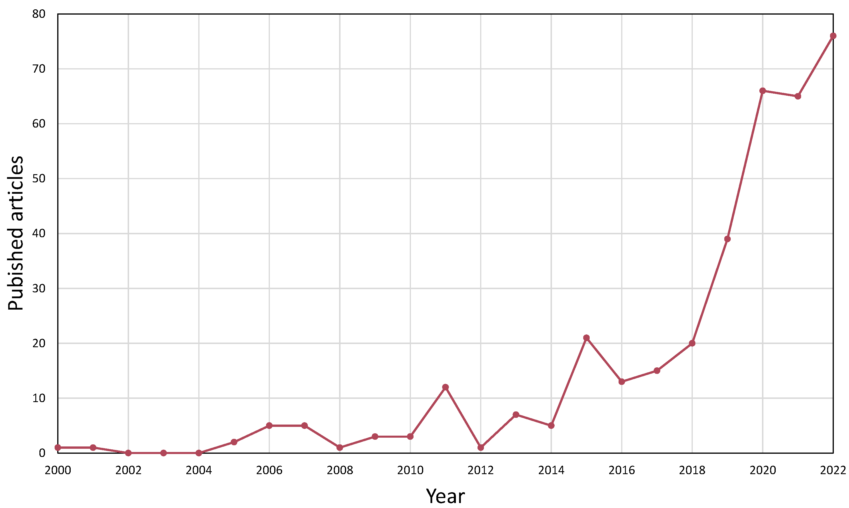
If we take a look at the last decades of published research on the overall topic in the Scopus database [
32] from 2000 to 2022, based on the keywords “co-simulation”, “multi-software”, “software linking”, “software coupling” paired with “hybrid model”, and “machine learning”, the following can be seen in
Figure 1. The number of published articles in chemical engineering have been exponentially increasing for the last five years based on this data, meaning it is a current topic to study. Moreover, the co-occurrence of keywords in the corresponding articles are multifaceted; several different fields benefit from software connecting methods. Besides the keywords mentioned above, process simulation, optimization, and control appeared the most.
It is worth mentioning that, although the ideas behind connecting process simulation software with each other or an external tool have existed for two decades [
6,
7], there is still no collective name for them. Software linking, software coupling, software integration, co-simulation, hybrid model, or multi-software modeling are often used to describe such processes. Therefore, finding adequate literature on the topic of chemical engineering is quite challenging sometimes; in the current paper we proposed the use of the term multi-software engineering.
We present an application example where the shortcomings of commercial process simulators with restricted reaction kinetic structures can be solved, where we identify simpler reaction kinetics for
-valerolactone (GVL) production, so the reaction system can be calculated. The product itself was derived from biomass, of which valorization is a highly researched topic in today’s era of food, fuel, and economic crisis [
33].
-valerolactone in this case was produced from butyl-levulinate with catalytic hydrogenation, the kinetics of which are rather complex. For the identification of a directly implementable reaction kinetics, we implemented the dynamic simulator of the GVL production reactor using Aspen HYSYS, and we identified the reaction kinetic parameters using a MATLAB optimization algorithm.
A major shift in process development has been happening for the last few decades with the appearance of reliable data-driven models. Process simulators that are inherently based on first-principle models are reaching a limit of accurately representing more complex problems, not to mention the factor of time and cost. Multi-software engineering is a novel tool for connecting a priori and a posteriori models, in the form of robust process simulators and statistical solvers to keep up with the evolution of information technology. Our contribution to the current state-of-the-art of this research field and the road-map of this paper is as follows:
We systematically organized the available novel research regarding the application of multi-software engineering in the chemical industry (see
Section 2).
We presented various process simulation software, numerical solver tools, and their connection methodologies applied to a wide range of complex engineering problems to serve as a reference guide for their utilization, suitable both for academic and industrial use.
We identified future challenges and the fields in which multi-software engineering can be beneficial, but not utilized yet (see
Section 2 and
Section 3).
We showed the importance of the CAPE-OPEN standard in the interoperability of different process simulator tools (see
Section 4).
Finally, in a case study, we developed a framework linking Aspen HYSYS with the MATLAB environment for kinetic identification, presenting the advantage of building a model in Aspen’s graphical interface, but also utilizing the computing capacity and custom operations that a MATLAB environment could provide (see
Section 5).
2. Literature Overview
In this section, we attempted to collect some of the most significant research in the field of multi-software engineering. Showing the utilization of various software linking systems to solve complex and diversified problems in the chemical industry, in the hope of shedding light on this developing research area of Computer Aided Process Engineering. The following articles were chosen to showcase the most used simulation environments and numerical tools, their linking possibilities and to highlight the fields of application in four categories; process modeling, process design and optimization, process control and safety, and data-driven methods.
2.1. Process Modeling
If we take a look at the earlier literature on this topic, in the work of Fontalvo et al. [
7], multi-software modeling was presented as a tool for calculating the behavior of a membrane unit. An Aspen Plus distillation tower model was connected with a MATLAB subroutine, that was used to attach the model to a membrane unit. No descriptions were made of the connection between these two software or the implementation because the focus was on solving the actual modeling problem, rather than presenting the framework used for the software connection. Later on, one could notice a shift in the literature, where software linking will be more and more showcased, rather than just mentioned as a tool for problem-solving [
10,
23,
24].
As a continuation of the early idea of linking process simulators with coding environments, in Fontavlo’s [
34], a decade later, the principles of the process were finally described. An Aspen Plus and MATLAB hybrid system was created with an MS Excel connection, that was used in a distillation and vapor permeation process case study to show the protocol of utilization. In this case, the Excel spreadsheet worked as a mediator, which organized and sent information regarding stream results and additional parameters between the two software.
Kiss et al. used MS Excel, not only as a mediator but as a visualization tool. They studied an industrial sulfuric acid plant implemented in a dynamic simulation model with process simulator gPROMS and a graphical user interface created in Microsoft Excel [
35]. They could quickly develop an operator screen presenting the process flowsheet in Excel, while the data are exchanged between gPROMS and the spreadsheet. The developed dynamic model was capable of detecting changes in product quality, convenient for operator training and scenario evaluation.
In earlier software linking approaches, MS Excel was often used as middle-ware; mostly for data reading and organization. In later works, the use of a third software was less desired, as most commercial software vendors improved their connection methods, as could be seen in the following subsections. That way, a third software tool was only limiting the process, giving more space for errors.
In a recent study, Samei and Raisi tried to overcome the scarcity of commercial process simulation software regarding membrane units, with custom gas separation models [
36]. A code was first developed for mass transfer calculations, using the solution-diffusion mechanism in the FORTRAN programming language. Integration of this outside calculation to the flowsheeting simulator is made possible by the Aspen Custom Modeler (ACM) unit. This is a built-in feature of the Aspen Tech software, where additional equations could be described and implemented in the software without using outside tools.
Overall, the advantage of the direct relation between two software without the use of middle-ware includes; the reduction in computational resources, because there is no storing limit, avoidance of data loss, and the possibility to use the obtained database for data mining. Although, the use of a middle-ware could be necessary when working with multiple dynamic simulators.
In the works of Mikkonen et al. [
37], the dynamic co-simulation of multiple units were studied; a circulated fluidized bed boiler, air separation unit, and a CO
purification unit, all communicating through MATLAB. For the boiler and turbine side, the software Apros was used, which is a tool for dynamic modeling power plants and turbine islands. For the air distillation and CO
purification side, Aspen Plus Dynamics was used. The challenge in connecting different dynamic models is the delay in their numerical integration times. Therefore, a mediator tool is needed, in this case in the form of MATLAB Simulink. This way a master program keeps the two simulators clock’s synchronized. Data transfer between two dynamic simulators is only possible while their clocks are in sync and the models can be reloaded.
However, many more studies can be found in which the reduction of energy consumption [
15], equipment comparison [
9], or properties estimation [
38] was discussed using multi-software tools for modeling.
Another field of software in modeling that often utilizes software linking is computational fluid dynamics (CFD). However, these cannot be labeled as typical process modeling simulators, rather as an expansion to observe and calculate transport phenomena inside a system. Zuhang et al. approached the municipal solid waste incineration (MSWI) process with numerical simulation methods and CFD software with their many difficulties [
23]. The investigated process is quite complex due to the different characteristics of the many subprocesses, therefore it is not feasible to perform the modeling with a single simulation tool. They reviewed the current research progress in the field and analyzed the proposed software coupling methods. The two main paths are based on self-developed or commercial software. In the latter, the combinations of FLUENT, Aspen Plus, MATLAB, Phoenics, Visual Studio, Flash, IMMS, Gaebed-ss, and ANSYS CFX can be found. They also mentioned that the development of a digital twin model is a possibility based on these software combination methods.
Da Rosa and Braatz [
39] used the open-source CFD software OpenFOAM for the multiscale modeling of crystallization and the 3D design software SolidWorks was used to generate the computer-aided design (CAD) model and to set and describe boundary conditions.
Egedy et al. [
40] used the CFD software COMSOL Multiphysics with a Livelink connection to MATLAB to study spatial and temporal changes of the viscosity and the density along the reactor geometry. Usually, optimization could be interpreted only as a comparison of scenarios [
41] in the case of CFD. However, with the use of external numerical environments, many black-box optimization algorithms are available. The connection with MATLAB made it possible to perform objective function-based optimization on the system to optimize critical parameters; initial catalyst concentration, process temperature, and pressure.
Finally, the most diverse tool for software linking has to be mentioned. Morales-Rodrıguez et al. investigated the integration of a set of diverse computational tools employing CAPE-OPEN, combining different Process Modeling Environments (PMEs) and Process Modeling Components (PMCs) to show the interoperability of the different computational tools [
42] by at first linking Simulis Thermodynamics as the graphical interface PME with ICAS-MoT as the PMC through a DLL file as the middleware. In another case study, they used a multiscale approach, with built-in unit operations found in the PME—ProSimPlus. The variables were obtained and calculated by the CAPE-OPEN unit operation using the ICAS-MoT solver. COFE as a different PME was also used in the calculations for the comparison of interoperability.
In this sense, another unique tool has to be showcased, which supports the interoperability between different coding environments. MOSAIC is a web-based modeling environment with a unique modular equation-based modeling tool, using the concept of symbolic mathematical language and code generation [
43]. It allows the re-usability of models and model parts. The functionality of code generation is that mathematical content is documented with standard and widely used languages (e.g., LaTeX), then the specified model’s program code can be directly rendered to different languages. This makes them suitable for integration into many different numerical environments, without prior knowledge of them.
Tolksdorf et al. implemented a model-driven approach for customized code generation for simulation and optimization purposes [
8]. The many case studies were carried out in an equation-based flowsheet simulation using CAPE-OPEN interfaces, to highlight the strength and variety of these methods. First, a simplified membrane module was described with MOSAIC modeling and Python code. An integrated mixer and splitter unit operation with two outlets was created with the code generated by MOSAICmodeling and SciLab’s “fsolve” function was used as a solver. Using CAPE-OPEN, SciLab unit operations can also be solved inside COFE and Aspen Plus flowsheeting simulators, showing the versatility of the software linking. A final example of a differential-algebraic equation system describing a system of two reactions and three compounds was investigated using MATLAB for code generation and as a solver.
As shown by the collected research data in this section, one of the most applied fields for multi-software engineering regarding the chemical industry is modeling. Software linking is often utilized in modeling complex unit operations, where the model is built in a commercial simulator and an external numerical solver is connected, in which custom equation systems are solved to support the development of an adequate model. In
Table 1, we organized and categorized the above-mentioned works by application.
2.2. Process Design and Optimization
In the previous section, we could see a plethora of application examples for multi-software engineering, mostly single-unit modeling and solving custom operational problems. This method is powerful enough to be applied to whole chemical plants and processes with multiple different unit operations. In this subsection, we focused on showing the application to mainly optimization problems, which include multiple equipment and processes.
For example, Bayoumy et al. took a step further and, instead of optimizing a single unit, applied the previously mentioned Aspen HYSYS and MATLAB connection to an extensive green-field saturated gas plant with numerous components and operational units [
12]. In their case, a steady-state simulation was optimized using a merge between sensitivity analysis and stochastic optimization techniques.
Zhu et al. took an in-depth look at a multiple gas feed sweetening process and aimed to develop a superstructure using a simulation-based framework [
13]. They also collected literature data from the past 5 years of simulation-based optimization methods and software used, focusing on the algorithm in each case.
Aspen HYSYS linked together with MATLAB is often used in various optimization problems regarding the oil industry, namely, genetic algorithm (GA) [
14,
45] and particle swarm optimization (PSO) [
12,
46] techniques are used mostly in plant optimization tasks as the following works describe.
For process optimization and structure comparison with the same software framework, a PSO algorithm could be used [
47,
48], but GA provides greater confidence than PSO in optimization with wider ranges of constrained bounds [
12].
Li et al. used the SADDE algorithm in a MATLAB and Aspen Plus environment for an ethylbenzene and styrene separation distillation unit [
49]. Ruiz-Femenia et al. developed a Generalized Disjunctive Programming (GDP) framework for a bi-objective problem, which aims to minimize the Total Annual Cost (TAC) and the Dow’s Fire and Explosion Index (F&EI) for process safety while finding the optimal values for the continuous variables and the best flowsheet configuration in a superstructure [
50]. The synthesis was simulated in Aspen HYSYS and the modeling framework was built in MATLAB and solved by the TOMLAB optimization environment. Superstructure optimization was also investigated for CO
capture, linking Unisim Design with MATLAB using a GA algorithm [
51]. Multi-objective optimization problems also utilize Aspen Tech software and the MATLAB environment using GA [
52,
53] and NSGA-II [
54] algorithms.
These works are great examples that show the many software that have to be involved in building and optimizing processes with multiple different operational units. One can also notice the importance of choosing the right connection method between software. With the use of metaheuristic algorithms instead of gradient-based ones, the problems of obtaining derivative information through the numerical noise can be avoided [
12].
Reducing energy consumption [
9,
15], improving economic performance [
16,
55], and optimizing emission values [
56,
57,
58] are other applications that often utilize multi-software engineering for the optimization task.
Mounaam et al. investigated an industrial sulfuric acid plant with a contact process and developed dynamic models for simulation and optimization purposes [
55]. The simulation was provided by Unisim Design; its graphical interface made it possible to use the developed model for operator training or digital twin technology for the real plant. It was connected with the programming language Python, where data reading and writing from the simulation were possible, and performed optimization with a parametric study for cost and
emission minimization.
Brambilla et al. [
16] performed an unconventional real-time optimization (RTO) with an offline simulation model built in UniSim Design. The optimal setpoints were obtained analytically, as a function of the feed, products, and energy price fluctuation.
Alabdulkarem and coworkers studied the optimization of a propane pre-cooled mixed refrigerant LNG plant to reduce power consumption [
15]. The optimization of the refrigerant mixture was carried out in MATLAB with Genetic Algorithm (GA), that communicated through the actxserver command which was used to create the HYSYS COM server to access the plant model and its variables.
Radó-Fóty et al. used Aspen Plus and MATLAB coupling for the optimization of a coke oven gas purification process based on gas composition requirements [
56]. The steady-state model in Aspen Plus sent the results to MATLAB, which was used to provide operational parameters for the technology. The validation of the model was carried out using industrial data.
Briones-Ramírez et al. focused on the procedure of linking Aspen Plus and MATLAB in an example of minimizing the number of stages in a Petlyuk sequence with a detailed multi-objective optimization [
59].
Furda et al. developed a steam process drive sizing methodology with the use of Aspen Plus and the MATLAB environment, in a case study to replace a condensing steam turbine with a backpressure one [
10]. As they found, previous utility system optimization problems mainly focused on process-side modeling, while the proposed method considered coupled stream- and process-side modeling and also implemented the real operational parameters of the industrial case study system [
60,
61,
62]. They also mentioned the lack of information regarding the interface linking methodologies and their capabilities and provided a detailed description to set up the Aspen Plus-MATLAB link via a local ActiveX server.
Batolome and Van Gerven also found the lack of description for linking software; therefore, they studied different connection methodologies for the popular process simulator Aspen HYSYS [
24]. They described four interconnection approaches for data exchange—direct, indirect, internal spreadsheets, and data tables. A test was carried out with AspenTech example simulation files, both steady state and dynamic, to test the different connection methods to the different external tools—Microsoft Excel VBA, MATLAB, Python, and Unity respectively. Based on the evaluation of the results, the following three criteria were created—average connection time delay, accuracy of input connection, and overall consistency of output. The authors found that the internal spreadsheet connection performed properly in all cases, but found severe limitations in each case.
Optimization algorithms are usually not part of the process simulators, or their capacity is severely limited compared to the wide variety of algorithms implemented in coding environments (such as MATLAB/Python). Applying a suitable connection method, an external solver for these problems can be applied to use an appropriate and reliable optimization algorithm.
Table 2 contains the articles collected in this subsection with regard to optimization and sensitivity analysis.
2.3. Process Control and Safety
In the previous sections, we talked about equipment modeling, design, and process optimization applied to both dynamic and steady-state systems. Dynamic simulation models could be utilized to investigate process control and apply safety measures with the help of multi-software engineering too.
Tuan et al. designed the control system of a depropanizer column using the Aspen HYSYS and MATLAB-SimuLink co-simulation setup, where the control objective was to reduce the variation in product quality [
17]. The dynamic model of the distillation column was built in Aspen HYSYS, whereas MATLAB-Simulink was used for designing the model predictive control (MPC) for the multivariable process. The connection was made through MATLAB with the HYSYSLIB toolbox, which uses HYSYS spreadsheets to read and write data for system identification and MPC tuning.
Chinprasit et al. also developed a model predictive control (MPC) for a vinyl chloride monomer process by integrating the concept of plant-wide control and subsystem partitioning to reduce the complexity of the control system optimization [
63]. Aspen Plus Dynamics was used to model the thermal cracking, quench, and distillation processes; while in MATLAB-Simulink, the partitioned two squared linear systems were built by the MPC controller block. The connection between the software was built through the AMSimulation block in Simulink which utilizes COM technology.
Other simulators were connected with the use of MATLAB-SimuLink in multi-variable automation problems in the works of by Ryu et al. [
18] and Dos Santos Vidal et al. [
64]. Brambilla et al. [
16] implemented hierarchical controlling using MPC [
65] and real-time optimization tools for a distillation process, where the simulator was developed in UniSim Design.
From the above examples, it can be seen that MATLAB-SimuLink is a common tool for solving various control problems, as it includes many built-in toolboxes that can connect different flowsheet simulators with customizable control panels.
The following works are examples of applying multi-software engineering to safety problems. Mizuta et al. performed a detailed safety analysis regarding a runaway reaction during methyl ethyl ketone peroxide (MEKPO) production, where venting from a safety valve was constructed [
66]. Dynamic computer simulations were carried out in Aspen Plus Dynamics and the safety valve model was built in the Aspen Custom Modeler block. The model was validated by comparing the results against experimental data, using the Advanced Reactive System Screening Tool (ARSST).
Kummer and Varga demonstrated the use of the multi-software framework, applying dynamic HAZOP to a vacuum distillation column [
67]. They used Aspen HYSYS as the dynamic simulator of the process with OPC connection, which allows the reach of model variables and modification of the operating parameters of the process with MATLAB, where the data were being evaluated. The deviations to demonstrate controller failures were sent from MATLAB. The Aspen OTS Framework hosted the OPC server, where MATLAB was connected and the simulator was run. The OPC client used the server to access data from the simulator and to send commands too.
Designing control systems and incorporating process safety is another important area of the application field of multi-software engineering; we grouped these in
Table 3. Dynamic process simulators with control systems could be connected to external numerical solvers through built-in toolboxes utilizing COM or OPC connections, where custom algorithms are used for controller tuning and optimization.
2.4. Data-Driven Methods
Data-driven methods could be applied in any field with large data sets and are developing rapidly. The chemical industry is no exception, as these methods have many benefits compared to the classically used a priori model-driven methods. In the previous section, we showcased various optimization problems; in this section, data-driven machine learning tools are featured, which assist complex optimization and control problems applied to process models. Mushin et al. [
69] investigated the optimization of crude oil HDT processes, where Aspen HYSYS models were built to simulate real plant data. The obtained process data were used to develop bootstrap aggregated neural network models. They were used in a multi-objective optimization framework, where the minimization of model prediction confidence bounds as an additional optimization objective was added.
Zhu et al. developed an optimization framework for a cryogenic NGL recovery unit using deep learning-based surrogate models [
68]. Aspen HYSYS was used to simulate the cold residue reflux process, which was based on industrial data, to construct a dynamic simulation and implement control strategies. The objective was to maximize profit with a stable operation of the process. An optimization framework, with the use of a differential evolution algorithm, was built in Python to manipulate the operating conditions. For validation, two case studies were created to simulate changing market conditions.
With complex optimization tasks, it is often challenging to maintain computational time at a reasonable speed for obtaining solution convergence between steady-states. To overcome this limitation, surrogate modeling of digital twins could lower the time of convergence in process simulators by implementing machine learning methods in place of model-driven methods [
70].
Alhajeri et al. studied the performance of model predictive control (MPC) in an ethylbenzene production process, comparing fully-connected and partially-connected recurrent neural network (RNN) models [
71]. The simulation of the process was carried out in Aspen Plus Dynamics, while input signals were generated in MATLAB, linking the two software with a local message passing interface (MPI). Similarly, a Python script was created to send random control actions to the simulation for testing the open-loop prediction.
Reinforcement learning is a type of machine learning paradigm that is based on reward and punishment mechanisms and is often used in optimization problems. Kim et al. considered a deep reinforcement learning approach for the optimization of Single Mixed Refrigerant cycles for the LNG liquefaction process [
72]. The optimization objective was the minimization of refrigeration power, subject to the constraint of minimum temperature difference. The Deep Q-Network (DQN) framework was implemented in Python, while the process model was built in UniSim Design and MATLAB was used for delivering decisions. They also reported a similar computational performance between the DQN and GA methods. Hedric et al. also utilized reinforcement learning for the online tuning of MPCs in order to reduce nitrogen oxide emissions in an industrial selective catalytic reduction unit [
73]. The dynamic model was developed in the Aspen Custom Modeler (ACM) unit.
However, in order to apply the outcome of the model predictions to the real system, the used model/simulator should be an accurate representation of the fundamental system. Without validating experimental or industrial data, the conceptual model is considered invalid and the simulation model cannot be used reliably.
In this sense, the importance of data reconciliation has to be mentioned, as it could filter out random error and improve the quality of measured data for further usage in, e.g., process simulation. The measuring equipment is inevitably laden with error, which affects the data obtained, causing it to not satisfy balance equations [
74].
Farsang et al. studied the online monitoring of catalyst deactivation, where the main idea was to perform the simulator development and data reconciliation simultaneously [
11]. Industrial data from an online measuring system were available, but the standard deviation of the data set was large for the observed kinetic values. More accurate parameter estimation was possible with data reconciliation. The results could also contribute to the validation of online analyzers [
75].
Vaccari et al. used a geothermal power plant model built in dynamic simulator UniSim to analyze the behavior of pollutants present in the process and estimate the changes based on the current process conditions [
57,
58]. The model was developed based on real plant data and data reconciliation was performed via optimization internal to the simulation environments. Seman et al. utilized data reconciliation for the tuning of oil well models [
76]. With the proposed methodology, automatic steady-state detection and re-estimating of chosen parameters reflect the current operating conditions.
Table 4 contains the above-mentioned research on data-driven methods regarding multi-software applications.
2.5. Future Challenges of Multi-Software Engineering
There are a variety of engineering problems that multi-software engineering could be applied to, and looking at the last few years of research, the future challenges of the field can be identified. In this regard, the available literature is rather sparse when it comes to equipment sizing and scale-up. It is an aspect that affects operation and controllability, not to mention costs. Performing equipment scale-up is not an obvious operation, but a rather complex problem, that could utilize multi-software modeling, taking advantage of the ready-made unit setups that process simulators provide and the customization that can be achieved with numerical tools.
Sustainable practices are more and more desired in the industry, which means that the development of technologies based on recycled and/or nature-derived feedstocks is in demand. Dealing with such feedstocks requires a more complex molecule system with unique interactions and reactions to use that current process simulators are not ready to handle yet, as our case study (
Section 5) shows.
Another important terminology to mention is the Digital Twin technology that is widely developing in the industry for the main purpose of supporting Operator Training Simulations (OTS). A Digital Twin is a replica of a unit or process that can predict design failures if it is applied in early planning. Additionally, a dynamic Digital Twin can be operated parallel to the real process supporting decision-making and intervention, or simulate start-up and shutdown scenarios that are crucial in a process’ lifecycle. It is another example where multi-software engineering tools can be beneficial for building a robust dynamic simulator that is capable of handling such models.
The application of Machine Learning and Artificial Intelligence to chemical engineering problems through different software mediums is also more and more studied. Recently, AspenTech released a new version of the simulation software Aspen Plus V12, which includes basic neural network features. Incorporating data-driven methods inside commercial process simulation environments could significantly reduce computational time.
Although more and more vendors try to accommodate these needs, by releasing new features to their software, these commercially available simulators still cannot provide a full solution for modern engineering problems on their own. Custom modifications are often required by skilled engineers who must have extensive knowledge of other software on the market, as well as programming.
In the following sections, we collected the methods and available software for multi-software engineering use to serve as a guide for software connecting opportunities.
3. Linking Types for Multi-Software Applications
Depending on the application and the type of these flowsheet simulators, one can perform different connections between them or with an external tool. The use of middleware or specific built-in blocks is common. The main approaches are ActiveX (Component Object Model (COM) and Object Linking and Embedding (OLE)) and OPC (Open Platform Communication) connections.
ActiveX is considered an outdated framework for new development in software engineering [
77] but several process simulators put it to good use for external software linking purposes [
78]. It utilizes the earlier Component Object Model (COM) and Object Linking and Embedding (OLE) technologies for software to communicate with each other using scripting and perform data exchange with each other. It is designed for communication on a single hardware or inside a network. The COM server and its scripting is available for most commercial process simulators, such as Aspen Plus or HYSYS.
With OPC [
79], one can create direct simulator-to-simulator connections; that way, run time can be lowered and additional data loss can be avoided. However, a mediator tool is advised to be used, if e.g., one would like to connect dynamic simulators, as in this case the simulation clocks of each software run differently.
With some of the commercial process simulators native integration is also possible. One example of this type of connection is gPROMS Object for MATLAB (gO:MATLAB), which allows solving complex mathematical equations by calling a previously built model from gPROMS within a function in MATLAB [
80]. Similarly, gO:Run is a convenient tool for non-advanced users, as it makes it possible to execute previously built gPROMS models behind MS Excel VBA interfaces, where their standard functions can also be used.
Another example is Aspen Plus Dynamics (APD) and MATLAB-Simulink, where one can add the Aspen Modeler Block to the Simulink model to design the control system of a unit. When the APD model information is imported into Simulink, input and output signals can be defined with the same variable names and sequence as in the Control Design Interface (CDI) tool [
81].
A similar connection possibility exists in Aspen HYSYS, which is called the Extension Container, with which custom objects can be added to the simulation such as Unit Operations, Reaction Kinetics, and Property Packages. Those extensions become part of the simulation and participate in the simulation calculations akin to regular built-in HYSYS objects [
20].
Interfacing COMSOL Multiphysics with several external software is also possible via LiveLink [
82].
Integrating the MATLAB environment and its toolboxes enables the use of its functions while modeling. It allows you to call MATLAB functions from the COMSOL Desktop and import/export data from/to the MATLAB workspace. The MATLAB Simulink add-on with the LiveLink connection can be used for control system design and performing co-simulation of COMSOL Multiphysics models and Simulink diagrams. This kind of connection is also possible with MS Excel, where parameters and variables that are defined and modeled in COMSOL Multiphysics can be synchronized to an Excel worksheet creating data libraries and parameter lists, which later can be used to load in the COMSOL Desktop. For 3D designs, SOLIDWORKS and AutoCAD software can also be connected to COMSOL Multiphysics, where the creation of model geometries and the integration of multiphysics simulation are synchronized between the software for design optimization.
4. CAPE-OPEN Standard
For embedding models from external programs, another important tool has to be mentioned and that is CAPE-OPEN. Computer Aided Process Engineering or Computer Applications in Production and Engineering (CAPE) is a modeling approach to process engineering problems that implies computer-aided methods and tools [
83]. The CAPE-OPEN project lists a series of specifications that define software interfaces for process simulation environments. The CAPE-OPEN specifications are supported by the non-profit organization CO-LaN [
26]; the standard is uniform and available free of charge. Engineers often come across complex modeling problems and the solutions for them lie in different commercially available process simulation software. One can choose to develop a custom model to solve these problems or try to integrate the existing models into their simulator. Either way, it requires advanced programming skills and takes significant amounts of time and effort, although it provides only a temporary solution. The development of new versions in the modeling environments makes it difficult to integrate the new components and the difficulty of writing software interfaces is particular to the host modeling environment.
The standardization of interfaces that CAPE-OPEN provides for software vendors has the advantage of interoperability. One can differentiate between the two main elements of process simulation software, the Process modeling Environment (PME) and the Process modeling Component (PMC). The PME means a simulation program with a buildable process flowsheet and working thermodynamics. A PME equipped with a CAPE-OPEN plug allows any CAPE-OPEN PMC, such as unit operations or thermodynamic models, to be placed in the modeling environment without further interfacing needed. That means any modeling environment with a CAPE-OPEN interface from any vendor would be able to communicate with any CAPE-OPEN modeling component without the need for a communication channel or additional programming involved.
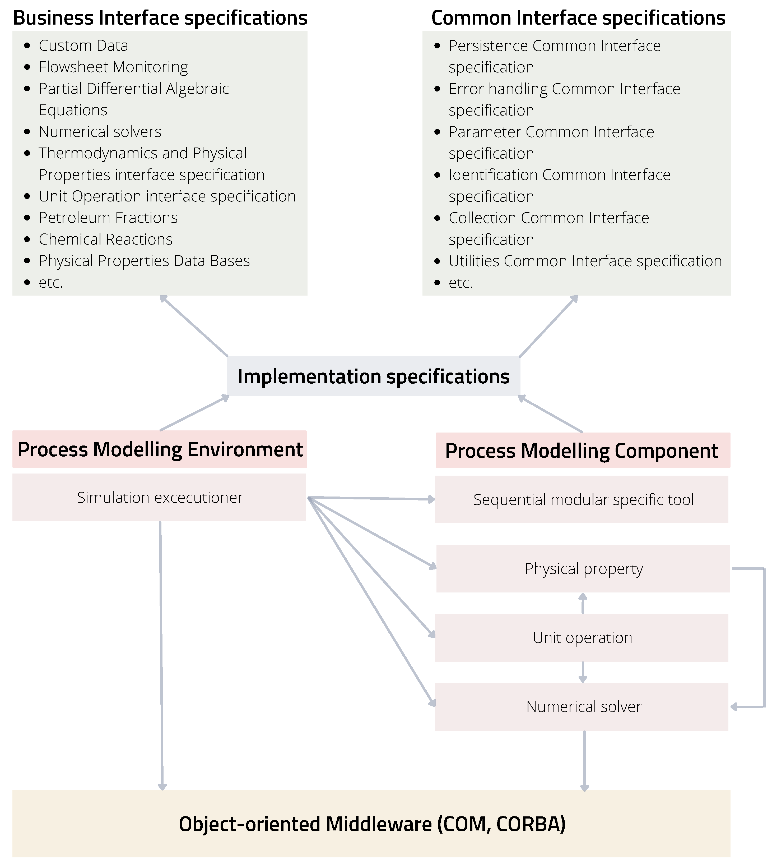
To allow such accessibility between several users, the CAPE-OPEN project classified standards for Business and Common interfaces as seen in
Figure 2. The former are vertical interface specifications, which are domain-specific and contain the main PMCs of a process simulation environment, such as flowsheet monitoring, unit operations, numerical solvers, thermodynamics, and physical properties. The common interface specifications are horizontal and contain basic functions such as utilities, error handling, or identification. They are general-purpose interfaces independent of business interfaces that support basic functions fundamental for CAPE-OPEN development. Another important part of the CAPE-OPEN structure is the communication platform, which allows interoperability between the software components PME and PMC. The object-oriented middleware technology that each object uses to communicate is Microsoft’s COM (Component Object Model) or the Object Management Group’s (OMG) CORBA (Common Object Request Broker Architecture); these models are described in the implementation specifications.
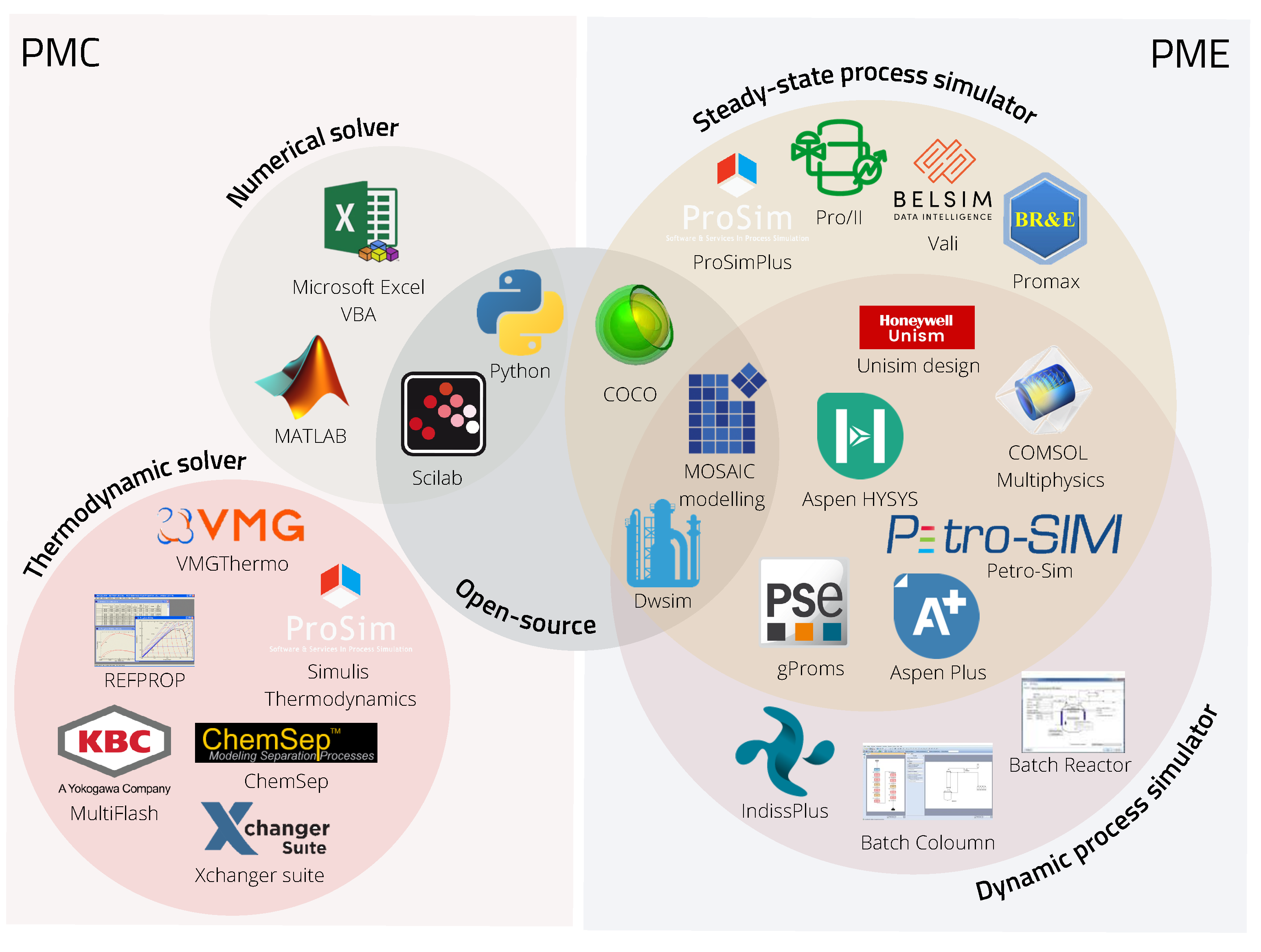
Figure 3 shows the classification of the assorted PMEs and PMCs that implement the CAPE-OPEN standard. The diagram also helps to distinguish between dynamic and steady-state simulation software. In addition, besides the commercial process simulators, freeware and openware were highlighted. The various in-house thermodynamics engines of bigger commercial vendors were excluded from this figure.
CAPE-OPEN is implemented in programming languages with an open source license, such as SciLab—developed for engineers and scientists—and also one of the most widely used languages in any coding-required field—Python. It is also available in openware such as DWSIM and freeware such as COCO simulator and MOSAIC modeling.
MOSAICmodeling is based on a LaTeX-style entry method for building custom equation systems to use for optimization, steady-state, and dynamic simulation purposes [
8,
43,
84]. It uses symbolic notation for automatic code generation for specific platforms (e.g., C++, FORTRAN, Python, SciLab, MATLAB, gPROMS, Aspen Custom Modeler, GAMS, AMPL, Modelica) that support reusability and portability. It is not designed as a full software; the web-based environment and the available database of models complement solutions for various chemical engineering applications [
85].
Another openware is DWSIM, which is a process simulator available on local computers or recently as a web application. A commercial web-based version of DWSIM Pro is also available [
21]. It includes solvers for both dynamic and steady-state simulations and various unit operations in both cases. It contains advanced property packages and thermodynamic models, just as commercial simulators, and has the option for Excel and Python plugins interface for thermodynamic calculations.
COCO (CAPE-OPEN to CAPE-OPEN) is a freeware simulation environment that includes a graphical user interface for flowsheeting (COFE—CAPE-OPEN Flowsheet Environment), thermodynamic library and property calculation methods (TEA—Thermodynamics for Engineering Applications), a set of unit operations (COUSCOUS—CAPE-OPEN Unit-operations Simple), and a kinetic and equilibrium reaction package manager (CORN—CAPE-OPEN Reaction Numerics) [
86].
The flowsheet simulator COFE is steady-state and belongs in the category of sequential modular flowsheeting engines, which means the sub-models, such as thermodynamic and unit operation models, are considered black boxes and are solved by an iterative function [
87]. COFE comes with an Excel template add-in, that deals with the documentation in an Excel workbook. It allows access to all streams and unit operations data, and thermodynamic property calculations can be performed too.
Unlike any other simulation environment, COCO was developed from the beginning as CAPE-OPEN-compliant; it is modeled around CAPE-OPEN interfaces. That means COCO does not use built-in sub-models that use the flowsheet engine’s proprietary interface, nor does it provide the option of user-defined models. Its components (TEA, COUSCOUS, COFE) are exchangeable to any other CAPE-OPEN component and work exclusively with such complaint models; additionally, any other third-party CAPE-OPEN compliant PME can utilize COCO’s PMCs.
Due to COCO’s unique structure and open access, it is often used for interoperability testing against third-party products, which helps with constant development and error detection, as well as the improvement of the CAPE-OPEN standard.
5. Case Study
The original task that inspired this case study was to build a dynamic model of a hydrogenation reactor based on the already existing data of lab-scale experiments from the work of Capecci et al. [
88], to further investigate the process. As a process simulation environment that is capable of dynamic simulation, Aspen HYSYS was available to us.
The original kinetic experiments were carried out in a batch reactor under isotherm and isobaric conditions, where non-competitive Langmuir–Hinshelwood kinetics with no dissociation of hydrogen were considered. The described rate expression model is a complex equation [
88] and the software is lacking some of the main correlations needed to precisely incorporate all the known data.
That is a common problem engineers and researchers have to face, when some of the key elements are missing to solve even more simple problems with the available software. Therefore, we needed to formulate new kinetics, based on the previous kinetic study, that could be used in the HYSYS environment and perform identification of the already available experimental data. In our case, an external numerical solver (MATLAB) was used to re-identify the reaction kinetics implemented in HYSYS. A co-simulation setup was chosen, as the integration of the two software give us the ability to run several simulation models, perform parameter identification, and validate the data at the same time from a main program, and that way obtain results in one go and organize the data in one place.
5.1. Simulator Development of the Case Study
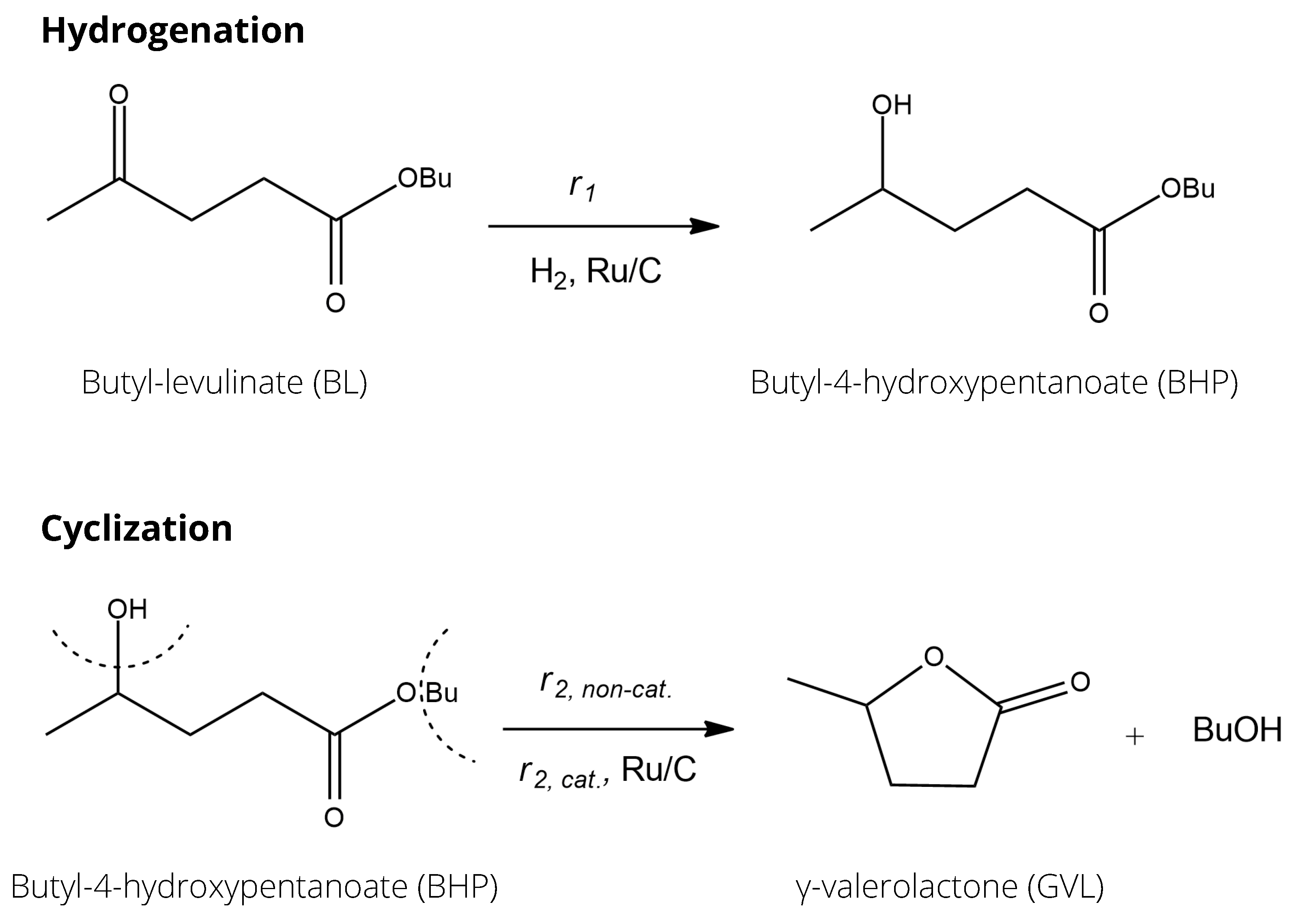
This case study aimed to show the identification of kinetic parameters with software linking for the production of -valerolactone (GVL) from butyl-levulinate (BL) in a two-step hetero-catalytic reaction over Ru/C catalyst.
Figure 4 presents the reaction network of GVL production; the first reaction was a catalytic hydrogenation reaction leading to the intermediate butyl-4-hydroxypentanoate (BHP). The second reaction was the cyclization of this intermediate, leading to the product
-valerolactone and butanol (BuOH). For the second cyclization step, both non-catalytic and catalytic pathways were possible, meaning the ring closure reaction happened on its own, but in the presence of the catalyst, it was faster.
-valerolactone was also used as a solvent, as the reaction is considered irreversible in solvent GVL. The hydrogenation is an exothermic reaction with an enthalpy of −38.6 kJ/mole. The catalytic cyclization reaction took place in the liquid phase on a solid catalyst and was endothermic; the enthalpy was +6.5 kJ/mole [
89]. This cyclization reaction was the rate-determining step.
When generating the simulation, kinetics were simplified to Arrhenius type for the three reactions present in the system. Equations (
1)–(
3) are the new kinetics created to describe the reaction system of the process. Equation (
1) represents the rate expression for the catalytic hydrogenation, and Equations (
2) and (
3) are the reaction rates for the homogeneous catalytic and non-catalytic ring closure reaction, respectively, where
is the pre-exponentinal factor,
is the activation energy in
,
R is the ideal gas constant in
,
T is the temperature in [K],
c is the concentration of the components in
and
is the catalyst loading in
.
The detailed description of the characteristics of the components as well as the setup used for the experiments are written in the works of Capecci and Wang et al. [
88,
89,
90]. Based on this, four series of experimental data were available for use, where the experiments were conducted under different conditions and the concentration change in time was measured for BL and intermediate BHP. Initial ratios of the mixtures, catalyst loading, temperature, and pressure values were collected in
Table 5.
Experiment 2 is different, as there was no catalyst present during the experiment and the intermediate was the starting material to investigate only the non-catalytic ring closure reaction. We chose to include this experiment to improve the fitting of the second ring closure reaction during the identification.
Four dynamic HYSYS simulation files were built according to the experimental setup in the aforementioned article, to be simulated in the HYSYS using the Soave–Redlich–Kwong (SRK) thermodynamic model. Arrhenius kinetics were considered for each reaction as mentioned before, where the pre-exponential factors and the activation energies could be reached via an internal HYSYS spreadsheet. In each case, the input parameters were varied based on the selected experiments in
Table 5.
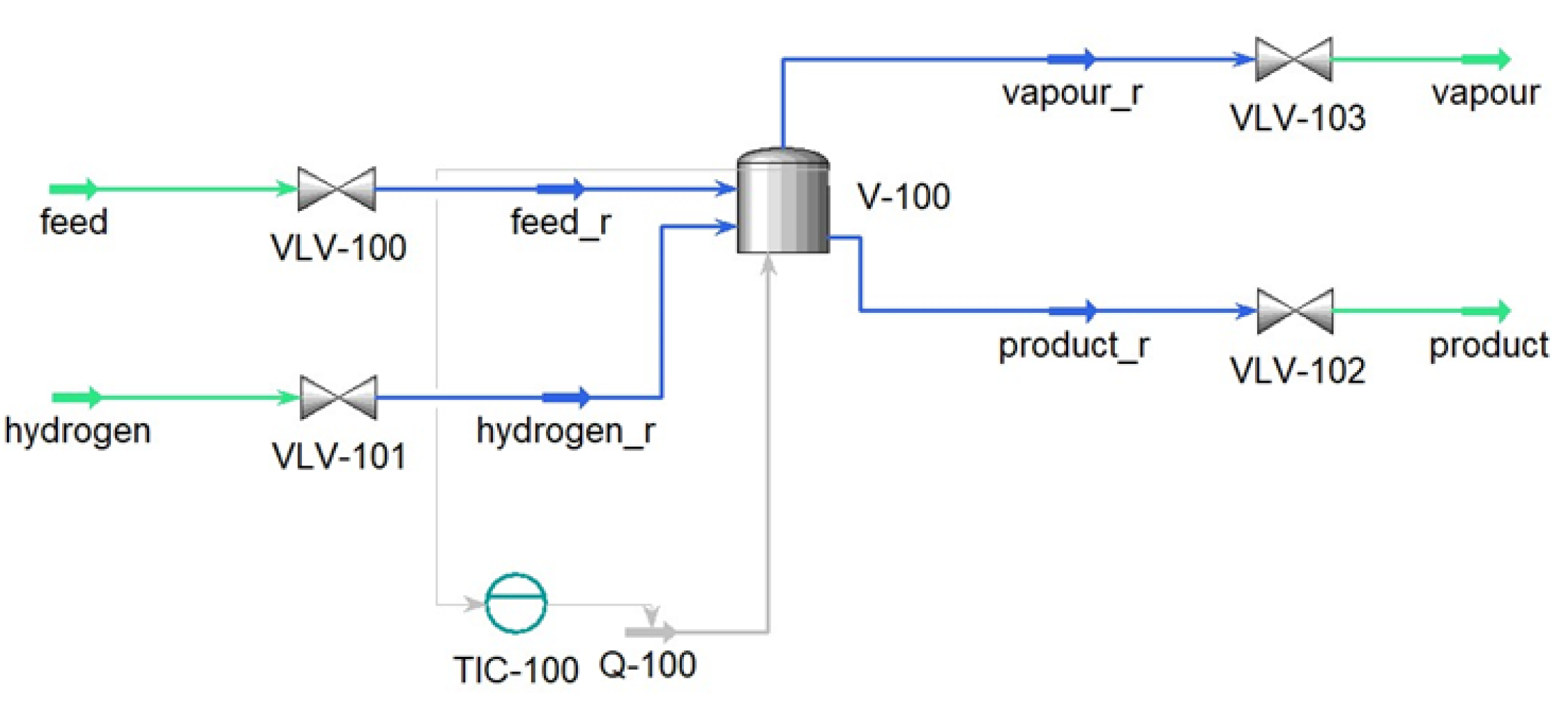
Figure 5 shows the unit design that contains a batch reactor equipped with a temperature controller to operate in an isotherm mode. Isobaric conditions were obtained with a high-pressure
inlet stream, similar to the experimental conditions.
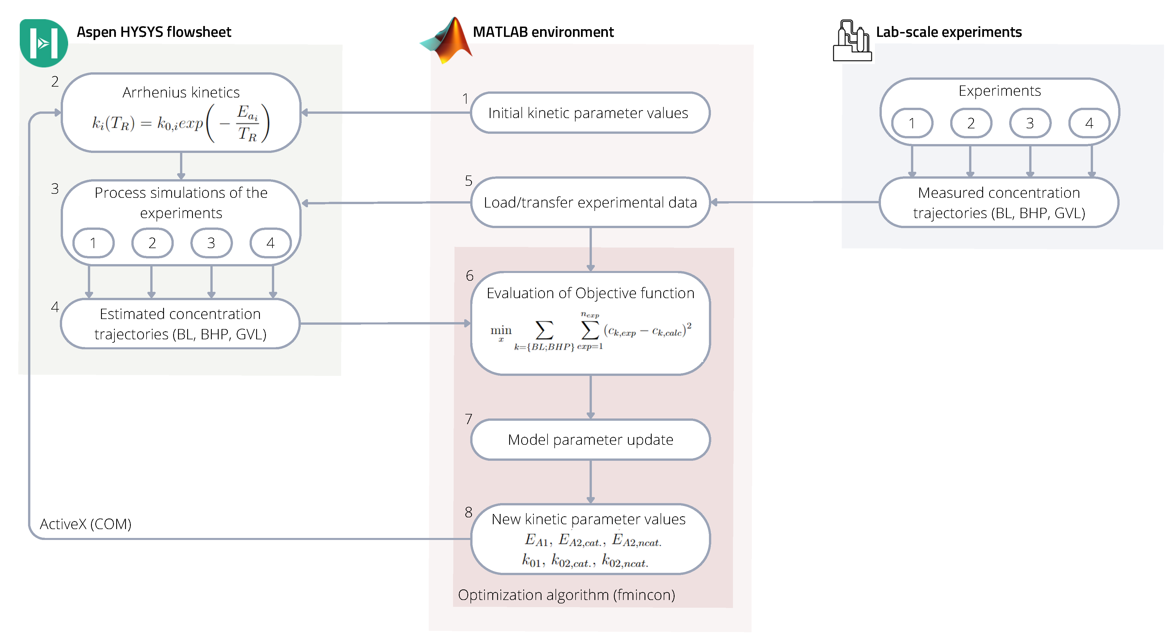
5.2. Multi-Software Based Identification Framework for Kinetic Parameter Identification
The kinetic parameters were identified by linking the HYSYS simulator to the MATLAB environment, where the latter acted as the main program. The connection was made using COM technology through the ’actxserver’. The previously built HYSYS models of the experimental cases were run from MATLAB, where modification to the kinetic parameters was made directly through HYSYS spreadsheets. The schematic identification framework is represented in
Figure 6.
The identification framework within the MATLAB environment calculated the kinetic parameters of the HYSYS files, where their value was varied in each iteration step to achieve better fitting to the experimental data sets in each case.
Based on
Figure 6 the framework works in the following way:
- (1)
The starting point of the sequence is running the MATLAB program, where, as a first step, it sends initial k and values to a previously set up internal HYSYS spreadsheet.
- (2)
Values overwritten in the spreadsheet modify the described Arrhenius kinetics in the HYSYS reaction sets.
- (3)
Then all four of the HYSYS simulations run with the new kinetic values until a set time (reaction time).
- (4)
The simulation results; concentration trajectories of the raw material (BL), intermediate (BHP), and product (BL) are transferred to another internal HYSYS spreadsheet.
- (5)
In the meantime, MATLAB reads and organizes the experimental data from text files.
- (6)
MATLAB will then import the concentration trajectories from the HYSYS spreadsheets and evaluates the objective function including the estimated concentration trajectories from all four simulations and all four measured concentration values from the experiments.
- (7–8)
Based on the normalized error values, in the next iteration step MATLAB will find new kinetic parameter values and send them to HYSYS to run the simulation again.
Equation (
4) represents the objective function, which is a minimum search with a quadratic error function including all data sets. To find the optimal point of the objective function, MATLAB’s nonlinear multivariable solver ’fmincon’ was used.
where
is the concentration of the components BL and BHP in
, indexed
for the measured data, meaning the experiments 1-4 in
Table 5 and
for the fitted data set from the HYSYS simulations.
5.3. Results and Discussion
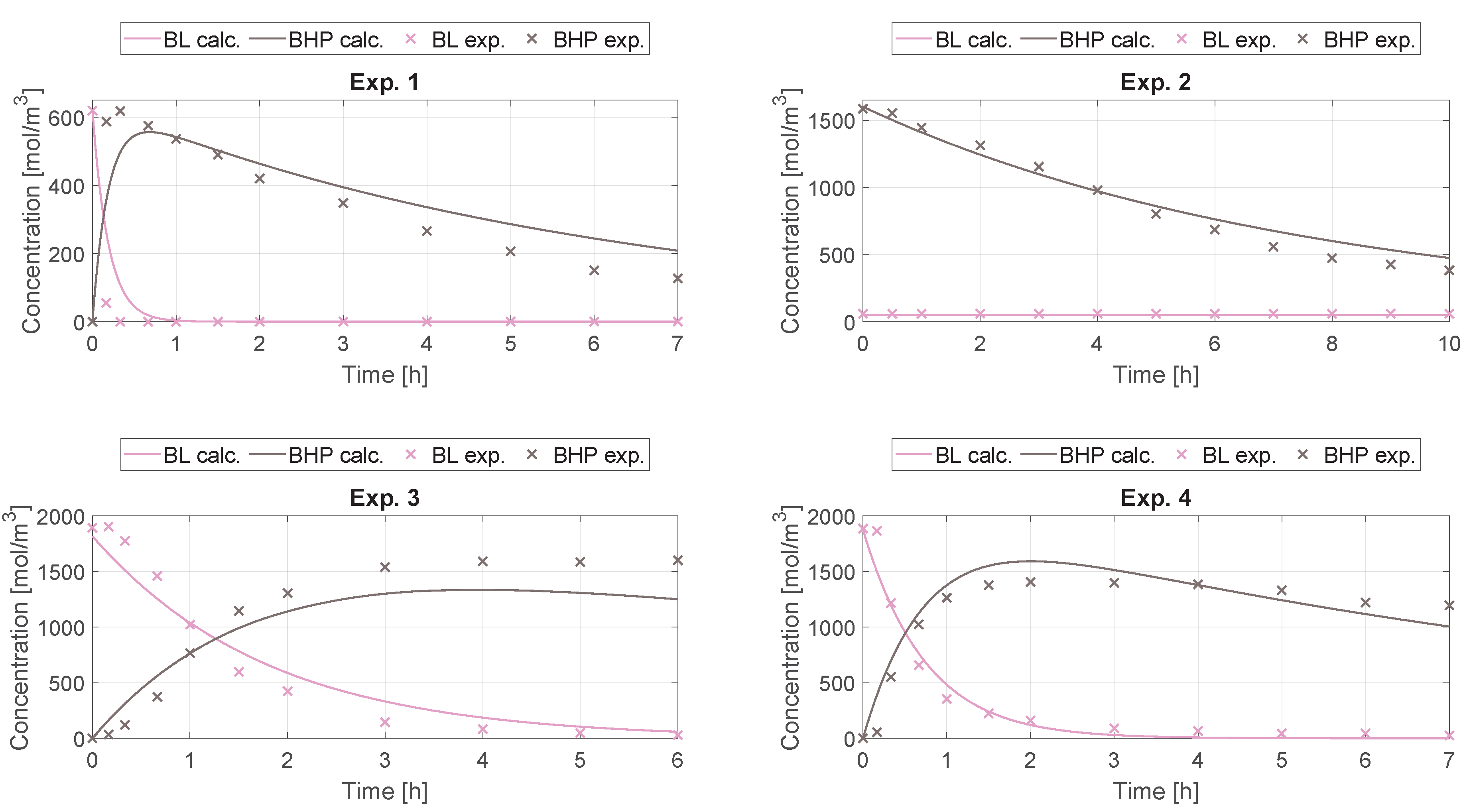
The results of the kinetic parameter identification for the process described in
Section 5.2 are shown in
Figure 7. It can be seen that the calculated concentration trajectories fit the measured data well. The identified kinetic parameters are in
Table 6.
To compare the performance of our simple kinetic model with Capecci’s work, the of their fitting to the concentration trajectories is 0.976 while ours is 0.952. The predictive ability of our simpler kinetic model is comparable with Capecci’s model based on the indicator.
The program was run with Aspen HYSYS V11 and MATLAB 2021b on an Intel(R) Xeon(R) W-2245 CPU 3.90 GHz, 32 GB; the computation time was 11 h and 15 min. However, it has to be mentioned that the computation time could be lowered with parallel computing.
6. Conclusions
In this work, the various applications of multi-software engineering regarding the chemical industry have been highlighted through adequate literature. We organized this prominent research into four categories—process modeling, process design and optimization, process control and safety, and data-driven methods. Custom unit operation modeling and process optimization were found to be the most utilized aspects. The integration methodologies that could link together multiple process simulation software and coding environments were also collected and studied in detail. The CAPE-OPEN standard was also showcased in detail, with a focus on presenting open-source software. Freeware and openware are important parts of the developing process, because of their wide accessibility.
In a case study, parameter identification with multi-software engineering was performed to illustrate one of the many application aspects of the technique. The problem was chosen to showcase the reality when the available process simulator is missing an important element for problem-solving. In our case, it was the lack of kinetics definition, which is crucial for model building inside a simulator. Therefore, a link between the dynamic process simulator Aspen HYSYS and the coding environment MATLAB was made utilizing an ActiveX connection. We found that the method provided good results and performed well in fitting the available experimental data.
Commercial process simulator vendors have to keep up with the rapidly developing information technology and the demand for modeling more complex processes. In the sense of connecting data-driven methods to this software, as for now, two main routes were shown—the possibility of native integration, specific to software, with customizable toolboxes, or improving the plug-ins to accommodate outside environments.


