Article

Failure Analysis of the Crack and Leakage of a Crude Oil Pipeline under CO2-Steam Flooding

1
State Key Laboratory for Performance and Structure Safety of Petroleum Tubular Goods and Equipment Materials & CNPC Tubular Goods Research Institute, Xi’an 710077, China
2
Research Institute of Experiment and Detection of Xinjiang Oil Field Company, CNPC, Karamay 834000, China
*
Author to whom correspondence should be addressed.
Processes 2023, 11(5), 1567; https://doi.org/10.3390/pr11051567
Submission received: 3 April 2023 / Revised: 4 May 2023 / Accepted: 18 May 2023 / Published: 21 May 2023
(This article belongs to the Special Issue Risk Assessment and Reliability Engineering of Process Operations)

Abstract

:
This paper presents the failure analysis of the crack and leakage accident of a crude oil pipeline under CO2-steam flooding in the western oilfield of China. To analyze the failure behavior and cause, different testing, including nondestructive testing, chemical composition analysis, tensile property testing, metallographic analysis, and microanalysis of fracture and chloride stress corrosion cracking (SCC) testing, are applied in the present study. The obtained results showed that the pipeline under the insulation layer of high humidity, high oxygen content, and high Cl environment occurred pit corrosion, and the stress concentration area at the bottom of the corrosion pit sprouted cracks. Besides, it is demonstrated that the cracks were much branched, mostly through the crystal, and the fracture showed brittle, which is consistent with the typical characteristics of chloride SCC. Meanwhile, the insufficient Ni content of the pipeline material promoted the process of chloride SCC, and the high-temperature working conditions also aggravated the rate of chloride SCC. In addition, efficient precautions were provided to avoid fracture.

1. Introduction

Dissolving CO2 gas in crude oil can improve the oil flow ratio and swell the crude oil to achieve the effect of enhanced recovery [1,2]. Moreover, in the global trend of carbon reduction, CO2 can be effectively buried in this way. Therefore, CO2 flooding has the economic benefits of recovery enhancement and social benefits of carbon reduction. The application of CO2 flooding is gradually increasing globally, but it is still in the stage of industrial trials and enhances the application of benefits [3,4]. The literature has so far focused on the study of oil reservoirs applicability assessment, production parameter control and optimization, and miscible effect of CO2 with crude oil [5,6,7,8], with few reported cases of failure of injection and recovery pipelines.
In the western oil field of China, there are many thick oil and super thick oil blocks. To improve recovery, in addition to using CO2 to reduce the viscosity of the crude oil, steam is also injected to improve oil washing efficiency and wave area again [9,10,11]. Given the increased corrosion of the recovery media caused by the artificial injection of CO2 and high-temperature steam, 316L stainless steel is used for the crude oil recovery pipeline to cope with internal corrosion. Moreover, this pipeline lay in the ground and was completely soaked in sanding water underground. The groundwater is mainly recharged by atmospheric precipitation, ground runoff and infiltration and discharged by underground runoff and evaporation. The annual variation of groundwater is about 0.5 m~1.0 m in the region. But, the pipeline is not coated for corrosion protection, except for the external surface, which is covered with an insulation layer.
Nevertheless, the 316L stainless steel pipeline suddenly leaked out after nine months of service. Figure 1 shows the failed pipeline sample after cleaning with water + paraffin. The material of the pipeline is manufactured according to ASTM-A312 [12]. This pipeline sample is Φ168 mm × 5 mm and 600 mm long. Table 1 presents the design and operating conditions of the pipeline which operating pressure, temperature and flow rate are within allowable limits. In this work, the pipeline’s material properties and cracking characteristics will be analyzed by several tests to clarify the causes of leakage failure. And the study results will provide a scientific basis for the selection of materials and corrosion protection of the pipeline under the new conditions of CO2-steam flooding.

2. Materials and Methods

2.1. Nondestructive Test

Nondestructive tests can visually detect defects such as cracks and pitting. Given that the material of the failed pipeline is weakly magnetic, as well as large corrosion pits, the penetration testing method is more suitable for the nondestructive testing of this pipeline. To facilitate testing, the pipeline sample was cut into four equal pieces. The external and internal surfaces of the sample are then cleaned with a cleaning agent and sprayed with a uniform layer of white penetrant. After waiting for 10 min, the penetrant is wiped off with a dry cloth, and then the sample surface is wiped with a paper towel soaked with cleaning agent until all the penetrant is wiped off. After the sample has dried naturally in the air, the surface is sprayed with a further layer of red developer. The resulting defect image is then observed and determined.

2.2. Physical and Chemical Performance Test

The chemical composition, mechanical properties and metallographic organization of metal pipes are the most basic physical and chemical properties, which are also the main basis for reflecting the corrosion resistance and strength of pipes. Firstly, an direct reading spectrometer (SPECTRO ARL 4460) was used to analyze the chemical composition of the pipeline body and corrosion pits area. Secondly, three parallel specimens (1#, 2#, 3#) were taken from the pipe’s body to test tensile properties by material testing machine (MTS 810), including tensile strength, yield strength and elongation after a fracture. Moreover, the microstructure, grain size and nonmetallic inclusion of the pipeline body and cracks were analyzed by a metallographic microscope and image analysis system (LEICA MEF4M). The above tests determine whether there are any abnormalities in the material properties of the pipeline.

2.3. Microscopic Characterisation Analysis

This pipeline’s corrosion morphology, products and cracking characteristics were characterized to analyze the mechanism of corrosion and cracking. The crack was mechanically opened, and the fracture morphology was analyzed using a scanning electron microscope (TESCAN VEGA 3). The surface products at the cracks were analyzed by an energy spectrum analyzer (XFORD INCA350) and X-ray diffractometer (D8 ADVANCE). In addition, the grains of the metallographic organization of the pipe body was subjected to energy spectroscopy by line scan to characterize whether there were changes in the elements within the grains and at the boundaries. Also, to determine if intergranular corrosion is a possibility. This leads to determining the possibility of intergranular corrosion.

2.4. Corrosion Test

Boiling magnesium chloride SCC standard test can determine the susceptibility of austenitic stainless steel to SCC. According to the standard of ASTM G36, three rectangular specimens (size: 75mm × 15mm × 2mm) were extracted from the pipeline sample. The specimens were bent U-shaped with an indenter with a radius of 8mm. Then the 42% MgCl2 solution was added to the experimental vessel with a thermometer and condensation tube. The solution will be heated to a constant boiling point of 155 ± 1 °C and then put the specimens into it. And their appearance is monitored periodically at 1h intervals. The susceptibility of the pipeline to chloride SCC is determined by observing whether cracks develop on the surface of the specimens.

3. Results

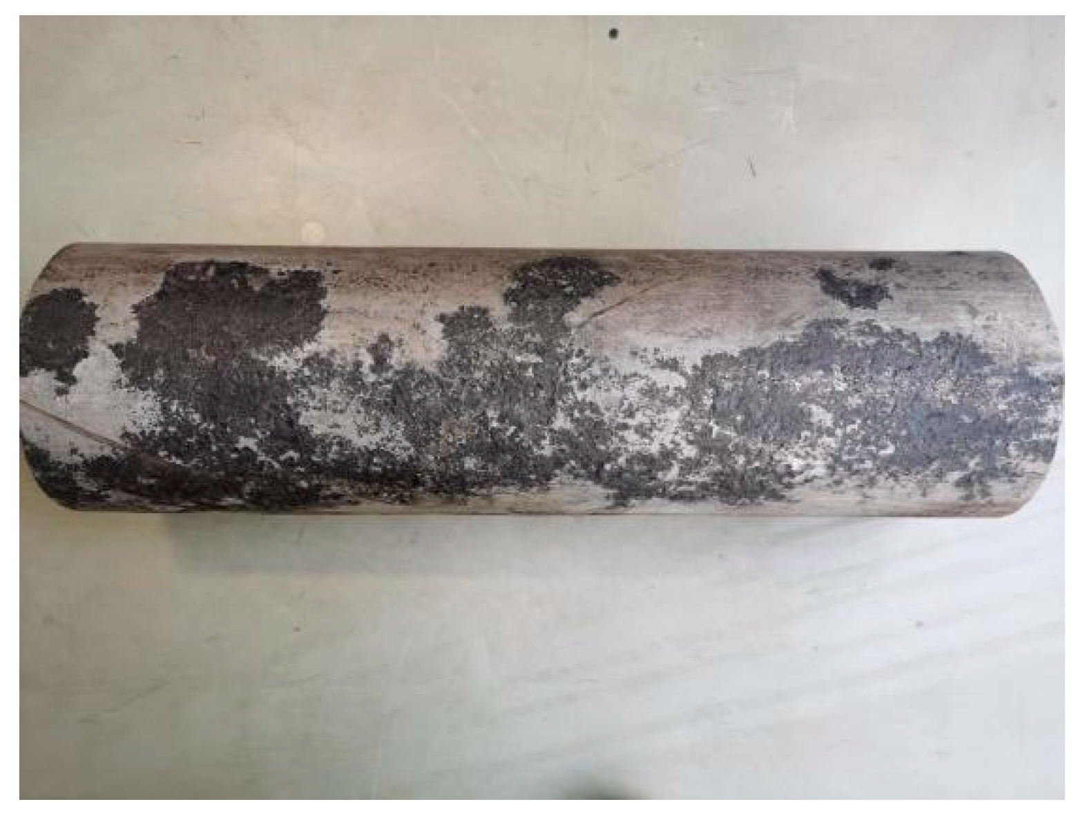
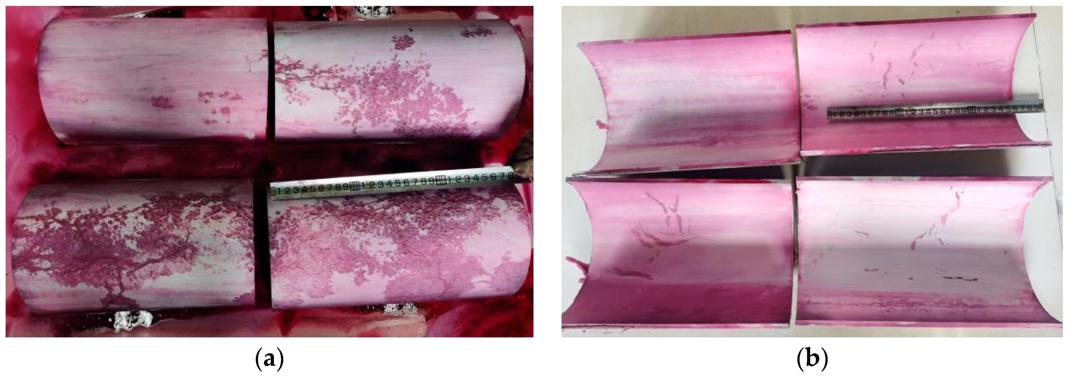
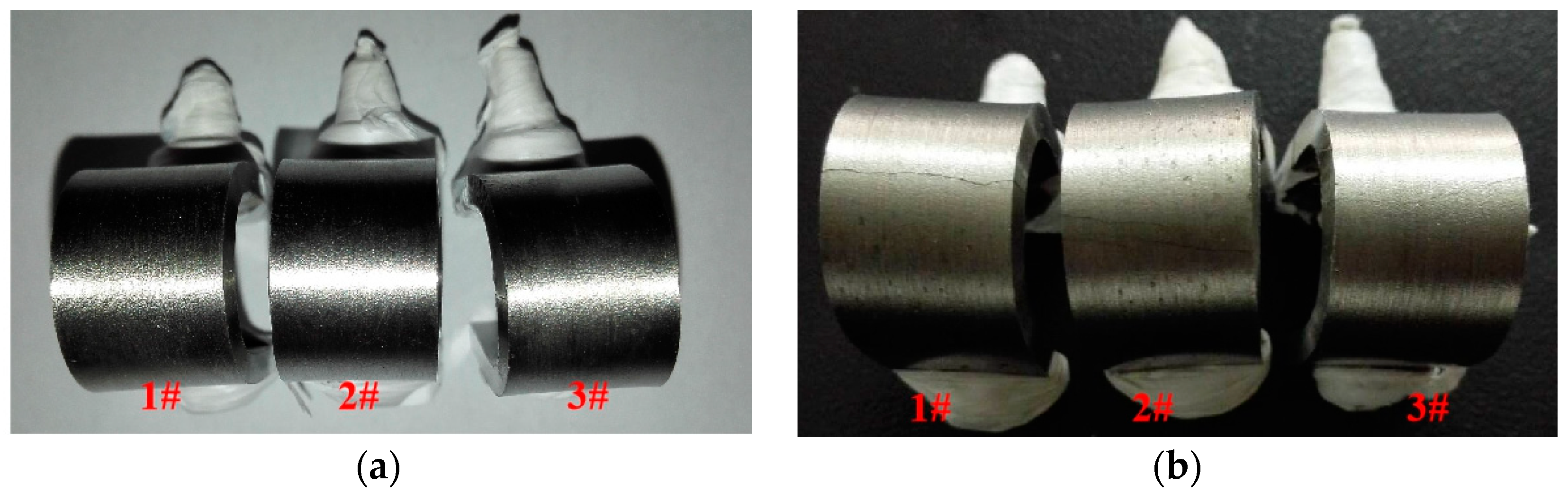
3.1. Visual Inspection

Figure 2 shows the external wall of the pipeline, which had a large contiguous blackened area. It results from dense corrosion pits in which some oil has been deposited. The depth of these corrosion pits is generally in the range of 1~2mm. Furthermore, corrosion pits and cracks are in the same area. The multiple crack crosses are observed at the bottom of the pits 30~150 mm in length. The main cracks are distributed along the pipeline transversely and longitudinally, as indicated by the arrows in Figure 2. The uncorroded area had a bright metallic luster, and no cracks were found. This suggests that uneven corrosion of the pipeline has occurred.
Figure 3 shows that the internal wall of the pipeline possessed multiple cracks at the same location as those on the external wall. Hence, penetration was suspected, but no corrosion pits were observed in the internal wall. Therefore, it should be indicated that the inner wall corrosion of the pipeline is not apparent under the fluid medium and working condition.
Figure 4 shows that the cracks originated from the external wall and expanded continuously to the internal wall according to the cross-sectional observation. It is more visualized and proved that the external soil environment of pipeline operation is the main influencing factor of cracking.

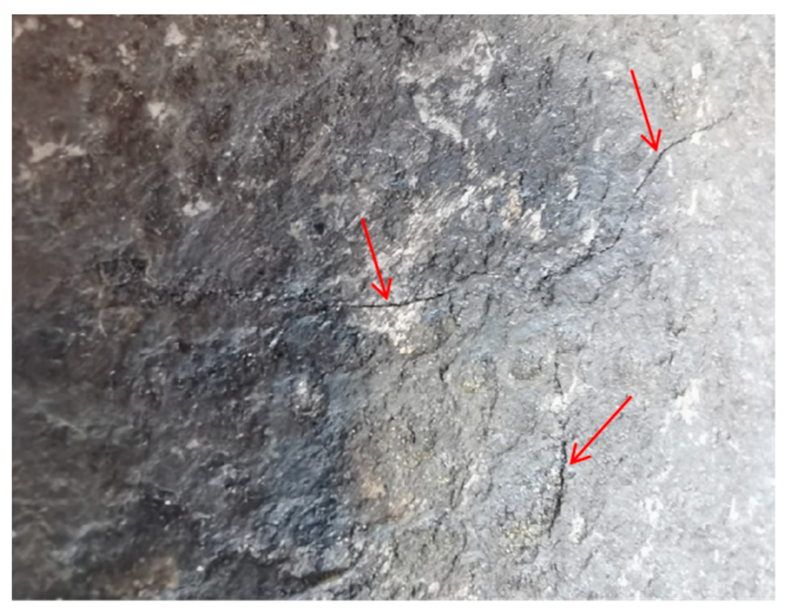
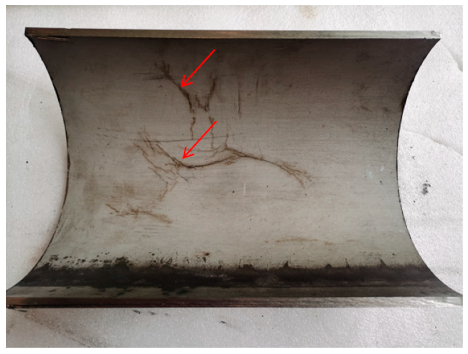
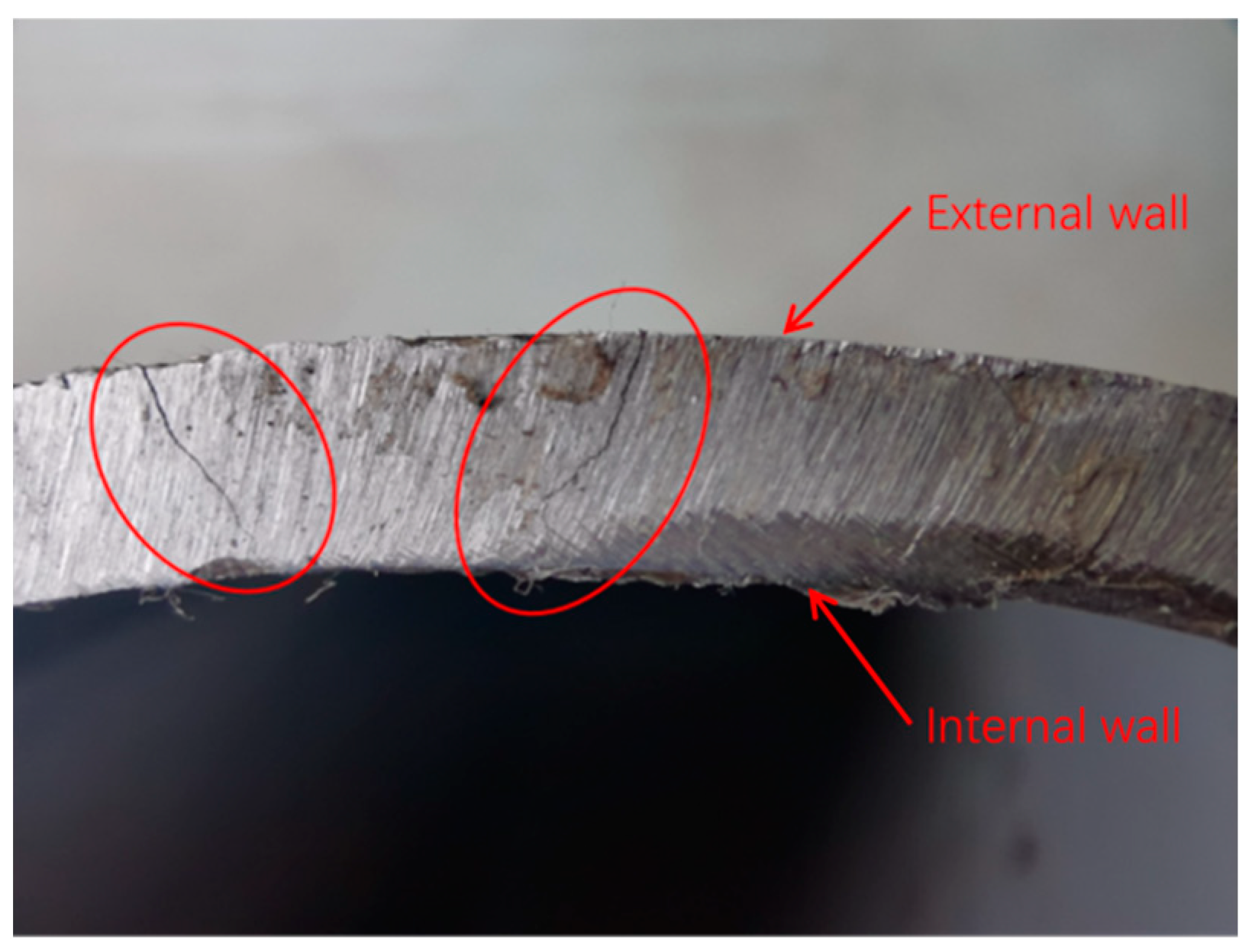
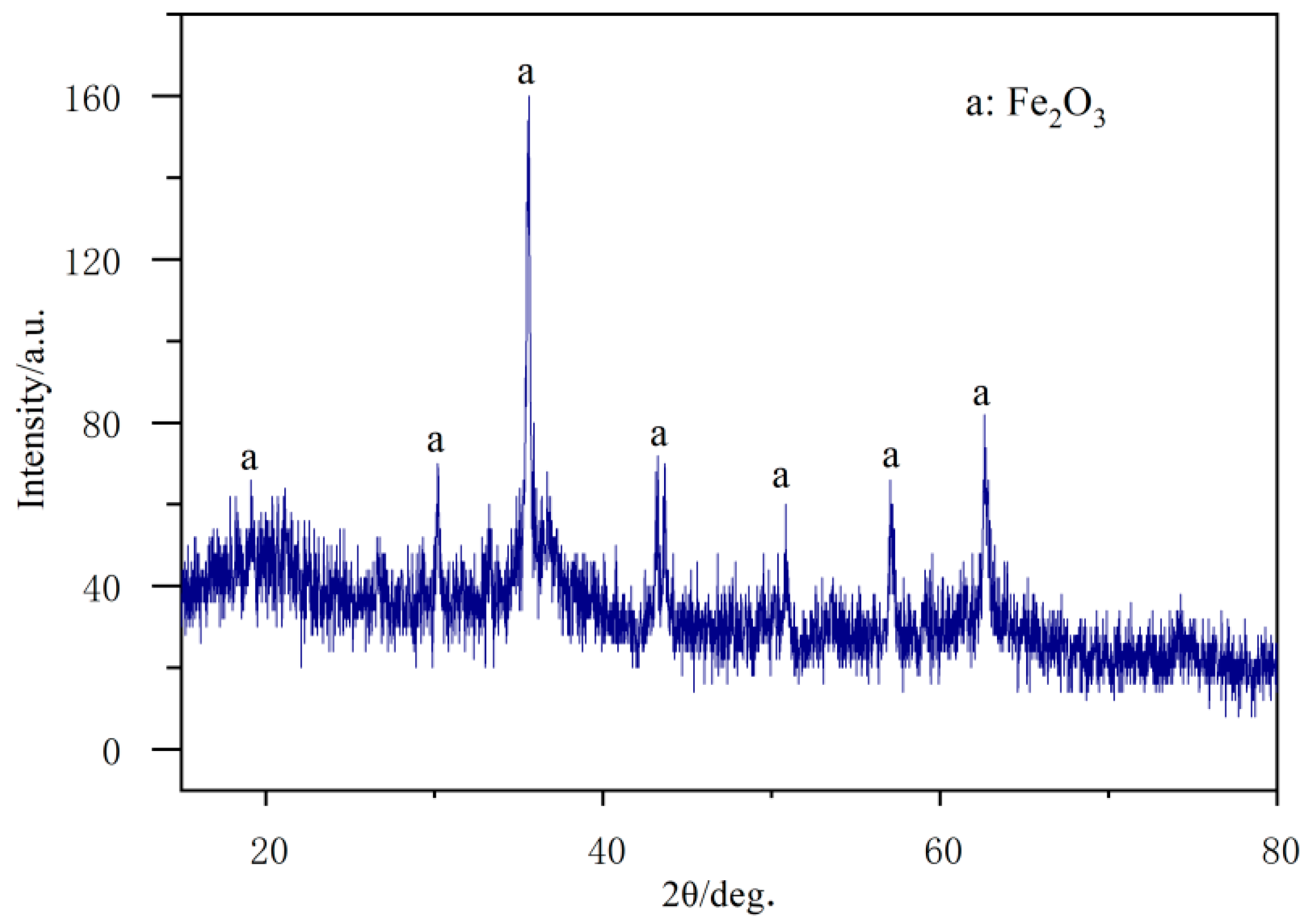
3.2. Nondestructive Test

Figure 5 shows the macroscopic morphology of the pipeline after the penetration test. Large defects are observed on the external surface of the pipeline sample, including corrosion pits and cracks. In addition, many obvious branching cracks are observed on the internal surface of the pipeline sample. The cracks on the external wall are concentrated in the corrosion pit area, where the majority are longitudinal, and the cracks are determined as penetrated.

3.3. Chemical Composition

Table 2 presents the results of the chemical composition analysis of the pipe body and pitting area, in which all elements are within the standard requirements except for the nickel content. The nickel content is lower than the lower limit required by the standard of ASTM-A312, which is an unqualified product. Stainless steel materials are more corrosion resistant because of the addition of the alloy element chromium, molybdenum and nicke. Therefore, a reduction in nickel content will reduce the corrosion resistance of the material [13,14].

3.4. Tensile Property

Table 3 illustrates the obtained results of the tensile properties of the pipe body. The tensile strength, yield strength and elongation after fracture are consistent with the requirements of ASTM-A312 for 316L steel. In addition, it indicates that the pressure-bearing performance of the pipe material without defects can meet the design operating conditions.

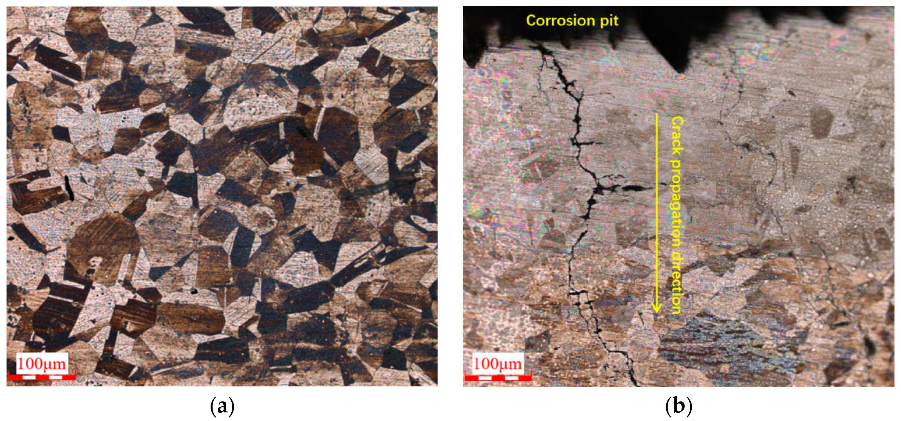
3.5. Metallographic Analysis

Figure 6 shows that the metallographic structure of the pipe body is austenite. No other abnormalities in the metallographic structure of nonmetallic inclusions and grain size. In addition, all cracks in the pipeline sample had similar characteristics, in which they all started from the external wall and extended to the internal wall. The cracks appear to be bifurcated, and no tissue distortion is seen. The main cracks are through crystal cracks, and part of the bifurcation is observed along the crystal fine cracks.

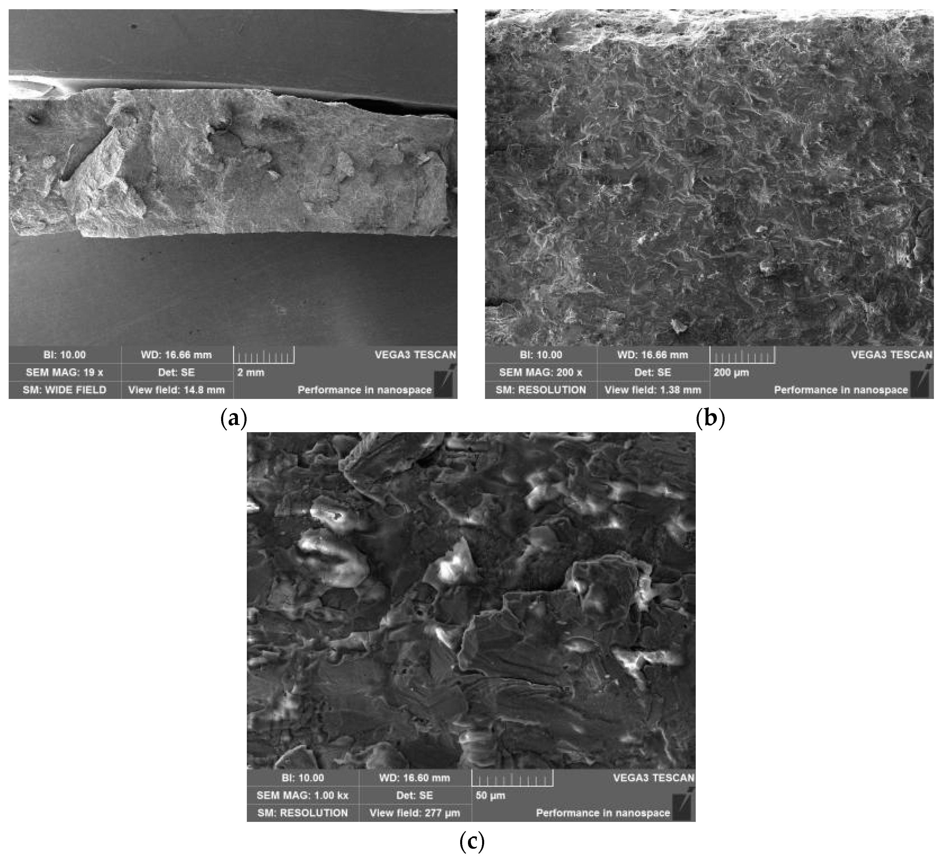
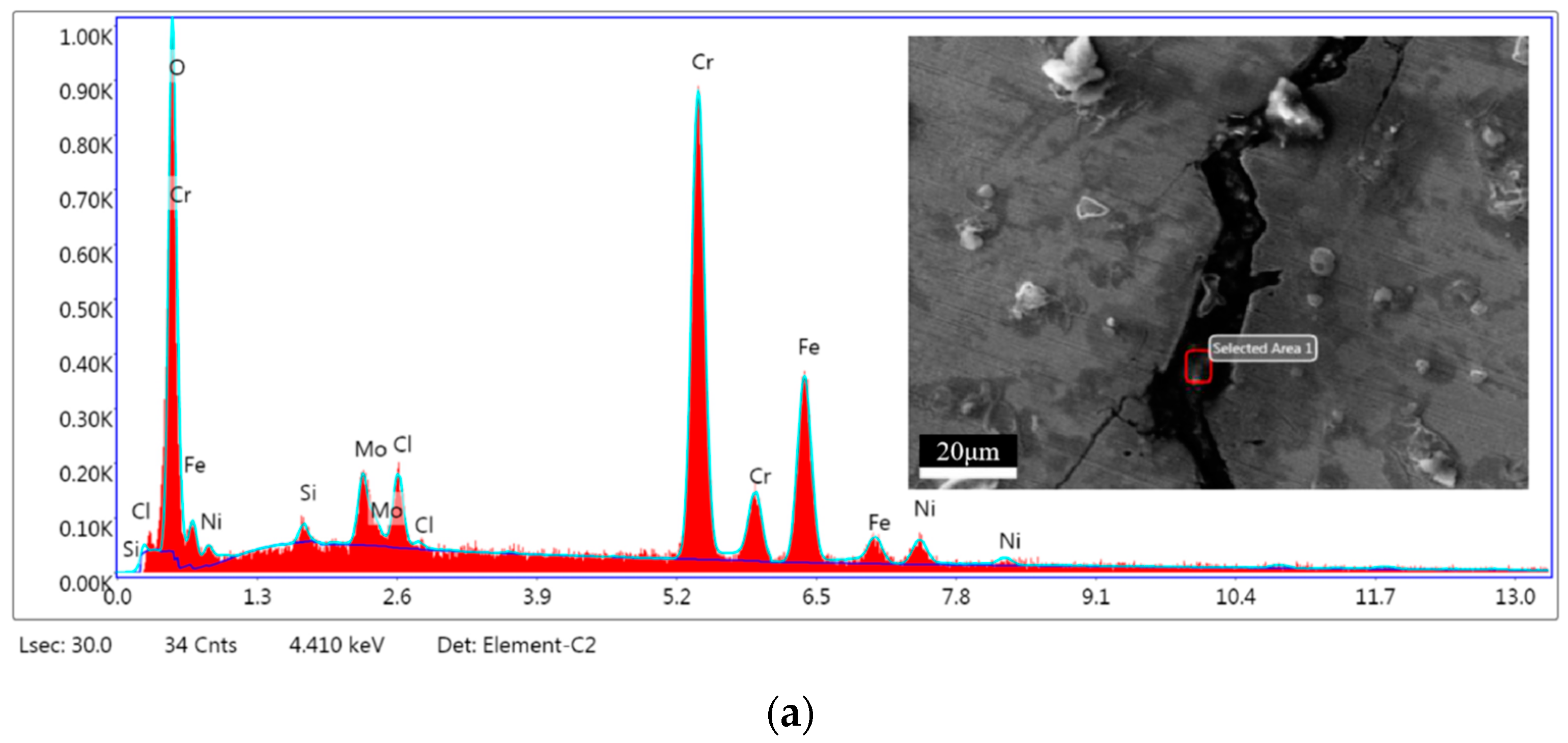
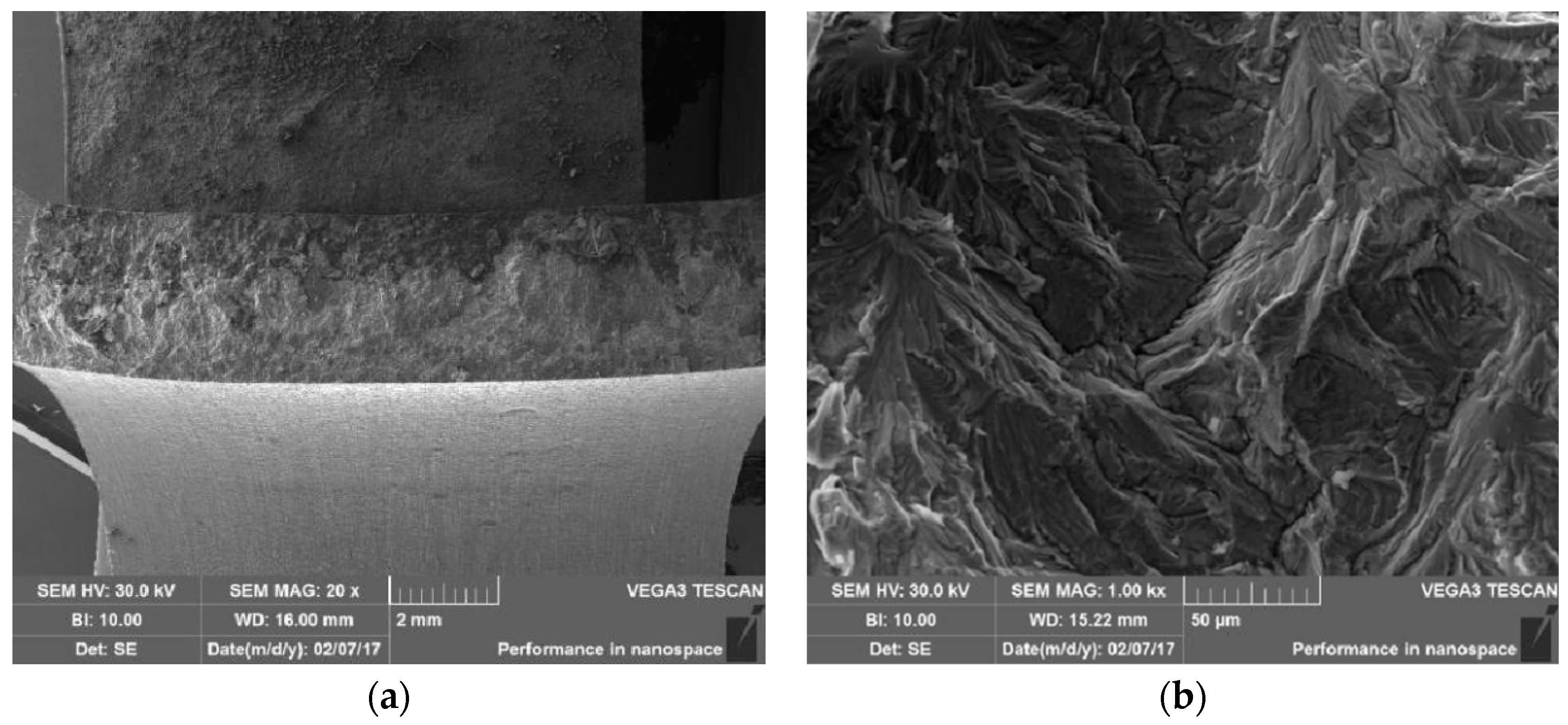
3.6. Microanalysis of Fracture

Figure 7 shows an SEM photo of the fracture at different magnifications. The fracture is flat, without necking, obvious deformation and thinning of wall thickness. As a result, this fracture indicates a clear, brittle fracture. Figure 8 and Table 4 show that the production elements within the cracks have O and Cl from external sources in addition to the metal matrix itself. The physical analysis of the product showed that it is mainly Fe2O3 which stems from oxygen corrosion, as shown in Figure 9.
Besides, Figure 10 shows the content of each element has no significant change along grain boundaries. Therefore, it shows no carbide precipitation at the grain boundary, excluding the possibility of intergranular corrosion.

3.7. Chloride SCC Test

After 20 h of the chloride SCC test, cracks appear on the surface of specimens (1#, 2# and 3#), as shown in Figure 11. And the cracks are mainly concentrated in the bending section of the specimen, with fewer cracks in the straight edge section, as shown in Figure 12.
To further analyze the crack fracture, specimen 1# is separated along the longest crack in the center. Figure 13a presents the upper part of the fracture is corroded, indicating that the cracking starts from the outer wall and gradually extends to the interior. Figure 13b shows a tearing ling-like quasi-dissociative fracture, which was typical fracture morphology of crystal penetration.

4. Discussion

The failure type of the pipeline is cracking, with the cracks starting from the bottom of the corrosion pit on the external wall and extending to the internal wall. Moreover, the branching of the cracks, which are mainly crystalline, and the fracture show brittle characteristics. Coupled with the fact that the pipe material is 316L austenitic stainless steel, it is judged that the failure of the pipeline is consistent with the significant characteristics of chloride SCC. SSC is a localized corrosion damage in metal materials under the combined action of tensile stress and corrosive media. The following three specific analyses regarding environment, stress and material will be carried out.

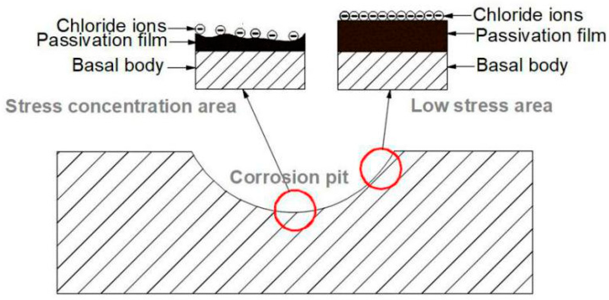
4.1. Corrosion Environment Analysis

It uses a cyclic injection process of CO2 and steam in the oilfield, resulting in a high recovery pipeline temperature of 98 °C. The API RP 571 standard describes the starting temperature at which chloride SCC occurs as 60 °C [15]. The API RP 581 standard states chloride cracking must be considered for environments above 38 °C under severe conditions [16]. Therefore, the operating temperature of the pipeline is sensitive to chloride SCC.
Macroscopic inspection reveals the existence of dense corrosion pits on the external wall of the pipeline, and XRD analysis further verifies the presence of Fe2O3, which is mainly a product of oxygen corrosion [17,18]. This is mainly because groundwater often contains dissolved oxygen from the air. Furthermore, it indicates that the insulation layer had broken down. Hence, localised pipeline corrosion is caused by underground water penetration into the insulation. Moreover, the higher the temperature, the more serious the corrosion will be, eventually resulting in large areas of pitting pits on the external wall of the pipeline.
In addition, underground water in the western region of China usually contains more Cl ions (200~1000 mg/L), constituting the basic condition for chloride SCC. At higher temperatures, the evaporation of water from the metal surface leads to a constant concentration and deposition of Cl ions. This will cause localised rupture of the stainless-steel passivation film. The formation of passivation-activation microcells at metal surfaces with and without passivation films will accelerate anodic dissolution and produce anodic polarisation [19,20,21]. As the corrosion pits deepen, small anodes and large cathodes will appear inside and outside, resulting in ever larger corrosion pits [22,23,24].
Moreover, it has been shown that the susceptibility to chloride SCC is significantly increased in the presence of both Cl ions and dissolved oxygen [25,26,27]. This is because the rate of oxygen consumption in the crack is greater than the rate of diffusion, leaving the crack tip still in a low oxygen state [28,29]. A corrosion potential gradient drives anions (e.g., chloride, sulphate, and hydroxide ions) deeper into the crack, while cations (hydrogen, sodium, and zinc ions) move outwards from the crack. This, in turn, causes the chloride ions to accumulate rapidly at the crack tip, creating very high concentrations. As a result, cl ions destroy the passivation film more quickly and further reduce the rate of passivation film formation [30,31]. The aggressive Cl ions invaded the grain in multi-directions promoted by dislocation motion, facilitating the main crack to bifurcate [32].

4.2. Stress Analysis

Corrosion pits have formed after significant localised corrosion has occurred on the external wall of this pipeline. Under operating pressure, soil pressure and other residual stress, there is a large stress concentration at the bottom of the corrosion pits. Residual stresses account for the largest proportion of several stresses because the pipeline is subjected to various processes, such as cooling, thermal processing, welding, etc., which can cause residual stresses. Besides, 316L austenitic stainless steel also has process hardening characteristics. The presence of stress makes the passivation film surface in the stress concentration area enriched with more chloride ions, which reduces the thickness, integrity of the passivation film, and pitting resistance [33,34]. This results in faster anodic dissolution in the stress concentration zone. In the low-stress area, the concentration of chloride ions is relatively low, and the passivation film thickness is greater and more complete, resulting in greater resistance to pitting corrosion. Figure 14 shows the model for stress corrosion of stainless steel.
The stress concentration area is prone to cracking [35,36], and the cracks in this pipeline all start at the bottom of the corrosion pits. As a result, once a crack has developed, the passivation film formed at the crack’s tip differs from that away from the crack [37]. It is much looser and less stable, leading to cracking of the passivation film. The corrosion rate at the tip of the crack will be higher than at other locations [37], thus allowing the crack to expand in a direction perpendicular to the stress. Once the formation of micro cracks, its expansion rate is much faster than other types of localized corrosion, so SCC is the most destructive and damaging type of corrosion among all types of corrosion.

4.3. Material Analysis

The composition of alloy materials, organizational structure, and heat treatment will also affect its SCC resistance. For example, austenitic stainless steel is generally considered susceptible to chloride SCC. In contrast, ferritic stainless steel and duplex stainless steel have better resistance to chloride SCC performance when exposed to Cl environments for long periods. This pipeline insulation layer broke down, resulting in groundwater containing Cl ions and dissolved oxygen seeping into the insulation. Thus, the environment of high temperature, high humidity, and high Cl- under the insulation provides favourable conditions for chloride SCC for 316L material.
In addition, Ni is the only important element to improve the stress corrosion resistance of austenitic stainless steel [38,39]. The standard API RP 571 also proposes that the Ni content of the alloy material is the most sensitive to chloride SCC at 8~12% [15], while the chemical composition analysis of the pipeline has a Ni content of about 9.9%, which is in the sensitive range of chloride SCC. At the same time, an EDS line scan of the pipeline grain structure revealed no significant change in alloying element content, ruling out intergranular corrosion cracking due to intergranular Cr depletion.
The accelerated test for chloride SCC confirmed that the pipeline cracked after 20 h of testing, and it can be concluded that the pipeline does have a high susceptibility to chloride SCC.
Based on the above analysis, it can be seen that the pipeline leakage failure process is divided into three stages. In the first stage, due to the presence of groundwater containing dissolved oxygen and Cl ions, the corrosion process was localized. Under the action of high temperature (98 °C), the local corrosion intensifies continuously. In the second stage, many cracks were generated at the bottom of the corrosion pits. In the third stage, due to the local concentration of stress and the continuous action of corrosion, the crack grew rapidly and led to the final failure of the material.

5. Methods for Chloride SCC Control of Stainless Steel

Three factors are required for SCC to occur: material, environment and stress. If any of these factors can be controlled, then it is possible to prevent or avoid the occurrence of chloride SCC in stainless steel.
Firstly, according to the specific environment in which the material is used, avoid using materials sensitive to chloride SCC. In general, in hot water and high-temperature water conditions, high chromium ferritic stainless steel, ferritic-austenitic duplex stainless steel, ultra-low carbon stainless steel and high nickel stainless steel can be considered to choose. However, in both, the need to resist SCC and require higher strength, ferritic-austenitic duplex stainless steel is more appropriate. On the other hand, in high concentrations of chloride media, ferritic stainless steel with low carbon and high chromium can be used, and high silicon chromium-nickel stainless steel is also a better choice.
Secondly, isolating the material from the corrosive environment is the most effective way to avoid SCC, such as using coatings or corrosion inhibitors. Reducing the concentration of Cl ions and operating temperature in the environment and preventing Cl ions adsorption and concentration are also the ways to slow down SCC. In addition, the mass fraction of oxygen should be reduced to a lower value when stainless steel is used to dissolve oxygen chloride.
Thirdly, measures should be taken during pipeline manufacturing to eliminate or reduce the residual stress in processing and welding. Surface treatment methods (such as shot peening, surface heat treatment, etc.) can also be used to reduce the residual compressive stress on the surface. Stress removal or elimination can also be performed using hydrostatic tests, temperature difference tensile and vibration.

6. Conclusions and Recommendations

(1)
The pipeline experienced localized external corrosion in groundwater containing dissolved oxygen and Cl ions, and leakage failure occurred due to chloride SCC in the stress concentration area at the bottom of the corrosion pits.
(2)
The Ni content of the pipeline material was lower than the standard product requirements and within the sensitive content range of chloride SCC, which accelerated the cracking of the pipeline. As well as the high temperature of the recovered medium under CO2 and steam combined flooding promoted the progress of chloride SCC.
(3)
Several Specific and practical recommendations are then proposed from both manufacturing and maintenance points of view. First, replacing the pipeline with 2205 duplex stainless steel pipe is feasible. Second, by reducing the operating temperature of the pipeline, the development of SCC will be slowed. Third, the buried pipelines should adopt an anticorrosion layer + cathodic protection to slow the occurrence of external corrosion damage under the new process of CO2-steam combined flooding. Fourth, similar pipelines need to be excavated for defect inspection and safety evaluation, and the severely corroded external pipeline section needs to repair by B-type sleeve, carbon fiber (or glass fiber) reinforcement, etc.

Author Contributions

Methodology, C.S.; Data curation, Y.L. and F.W.; Writing—original draft J.L. and L.L.; Writing review & editing, G.L. All authors have read and agreed to the published version of the manuscript.

Funding

This research was funded by Shaanxi Province Innovation Capacity Support Program Project (2023KJXX—091) and CNPC research found (2020D-5008).

Institutional Review Board Statement

Not applicable.

Informed Consent Statement

Not applicable.

Data Availability Statement

Not applicable.

Conflicts of Interest

The authors declare no conflict of interest.

References

  1. Yao, J.; Han, H.; Yang, Y.; Song, Y.; Li, G. A review of recent progress of carbon capture, utilization, and storage (CCUS) in China. Appl. Sci. 2023, 13, 1169. [Google Scholar] [CrossRef]
  2. Zhou, X.; Yuan, Q.; Peng, X.; Zeng, F.; Zhang, L. A critical review of the CO2 huff ‘n’ puff process for enhanced heavy oil recovery. Fuel 2018, 215, 813–824. [Google Scholar] [CrossRef]
  3. JLuo, S.; Hou, Z.M.; Feng, G.Q.; Liao, J.X.; Haris, M.; Xiong, Y. Effect of reservoir heterogeneity on CO2 flooding in tight oil reservoirs. Energies 2022, 15, 3015–3022. [Google Scholar]
  4. Jiang, K.; Ashworth, P.; Zhang, S.; Liang, X.; Angus, D. China’s carbon capture, utilization and storage (CCUS) policy: A critical review. Renew. Sustain. Energy Rev. 2019, 119, 109601. [Google Scholar] [CrossRef]
  5. Makarova, A.A.; Mantorova, I.V.; Kovalev, D.A.; Kutovoy, I.N. The modeling of mineral water fields data structure. In Proceedings of the 2021 IEEE Conference of Russian Young Researchers in Electrical and Electronic Engineering (ElConRus), Moscow, Russia, 26–29 January 2021; pp. 517–521. [Google Scholar]
  6. Makarova, A.A.; Kaliberda, I.V.; Kovalev, D.A.; Pershin, I.M. Modeling a production well flow control system using the example of the Verkhneberezovskaya area. In Proceedings of the 2022 Conference of Russian Young Researchers in Electrical and Electronic Engineering (ElConRus), Saint Petersburg, Russia, 25–28 January 2022; pp. 760–764. [Google Scholar]
  7. Wang, T.; Wang, L.; Meng, X.; Chen, Y.; Song, W.; Yuan, C. Key parameters and dominant EOR mechanism of CO2 miscible flooding applied in low-permeability oil reservoirs. Geoenergy Sci. Eng. 2023, 225, 211724. [Google Scholar] [CrossRef]
  8. Morgan, A.; Ampomah, W.; Grigg, R.; Dai, Z.; You, J.; Wang, S. Techno-economic life cycle assessment of CO2-EOR operations towards net negative emissions at Farnsworth field unit. Fuel 2023, 342, 127897. [Google Scholar] [CrossRef]
  9. Heidari, P.; Kordestany, A.; Sepahvand, A. An experimental evaluation of oil recovery by steam alternative CO2 injection in naturally fractured reservoirs. Energy Sources 2013, 35, 1498–1507. [Google Scholar] [CrossRef]
  10. Yuan, R.; Yang, Z.D.; Guo, B.; Wang, X.W.; Zhang, L.Q.; Lin, R.Y. Potential analysis of enhanced oil recovery by superheated steam during steam-assisted gravity drainage. Energy Technol. Gener. Conversion. Storage Distrib. 2021, 9, 2100135. [Google Scholar] [CrossRef]
  11. Liu, W.; Du, L.; Zou, X.; Liu, T.; Wu, X.; Wang, Y.; Dong, J. Experimental study on the enhanced ultra-heavy oil recovery using an oil-soluble viscosity reducer and CO2 assisted steam flooding. Geoenergy Sci. Eng. 2023, 222, 211409. [Google Scholar] [CrossRef]
  12. ASTM-A312-2018; Standard specification for seamless, welded, and heavily cold-worked austenitic stainless steel pipes. ASTM: West Conshohocken, PA, USA, 2018.
  13. Yu, H.; Luo, Z.; Zhang, X.; Feng, Y.; Xie, G. A comparative study of the microstructure and corrosion resistance of Fe-based/B4C composite coatings with Ni-added or Cu-added by vacuum cladding. Mater. Lett. 2023, 335, 133730. [Google Scholar] [CrossRef]
  14. Zhang, S.; Bian, T.; Mou, L.; Yan, X.; Zhang, J.; Zhang, Y.; Liu, B. Alloy design employing Ni and Mo low alloying for 3Cr steel with enhanced corrosion resistance in CO2 environments. J. Mater. Res. Technol. 2023, 24, 1304–1321. [Google Scholar] [CrossRef]
  15. API RP 571-2020; Damage Mechanisms Affecting Fixed Equipment in the Refining Industry. API: Minnesota City, MN, USA, 2020.
  16. API RP 581-2016; Risk-based inspection methodology. API: Minnesota City, MN, USA, 2016.
  17. Luo, B.W.; Zhou, J.; Bai, P.P.; Zheng, S.Q.; An, T.; Wen, X.L. Comparative study on the corrosion behavior of X52, 3Cr, and 13Cr steel in an O2–H2O–CO2 system: Products, reaction kinetics, and pitting sensitivity. Int. J. Miner. Metall. Mater. 2017, 24, 646–656. [Google Scholar] [CrossRef]
  18. Song, C.L.; Liu, X.B.; Pan, X. Failure analysis of the leakage and ignition of an oil–gas mixture transportation pipeline. J. Fail. Anal. Preven. 2022, 22, 259–266. [Google Scholar] [CrossRef]
  19. Zhang, S.H.; Hou, L.F.; Wei, Y.H.; Du, H.Y.; Wei, H.; Liu, B.S.; Chen, X.B. Dual functions of chloride ions on corrosion behavior of mild steel in CO2 saturated aqueous solutions. Mater. Corros. 2019, 70, 888–896. [Google Scholar] [CrossRef]
  20. Wang, Z.; Liu, Z.-X.; Jin, J.; Tang, D.-Z.; Zhang, L. Selective corrosion mechanism of CoCrFeMoNi high-entropy alloy in the transpassive region based on the passive film characterization by ToF-SIMS. Corros. Sci. 2023, 218, 111206. [Google Scholar] [CrossRef]
  21. Cui, Y.-W.; Chen, L.-Y.; Chu, Y.-H.; Zhang, L.; Li, R.; Lu, S.; Wang, L.; Zhang, L.-C. Metastable pitting corrosion behavior and characteristics of passive film of laser powder bed fusion produced Ti–6Al–4V in NaCl solutions with different concentrations. Corros. Sci. 2023, 215, 111017. [Google Scholar] [CrossRef]
  22. Cong, S.; Tong, K.; Li, D.F.; Chen, Z.X.; Cai, K. Leakage failure analysis of the ERW steel pipeline. Mater. Sci. Forum 2020, 993, 1224–1229. [Google Scholar] [CrossRef]
  23. Hua, Y.; Shamsa, A.; Barker, R.; Neville, A. Protectiveness, morphology and composition of corrosion products formed on carbon steel in the presence of Cl, Ca2+ and Mg2+ in high-pressure CO2 environments. Appl. Surf. Sci. 2018, 455, 667–682. [Google Scholar] [CrossRef]
  24. Zhang, B.; Ma, X.L. A review—Pitting corrosion initiation investigated by TEM. J. Mater. Sci. Technol. 2019, 35, 1455–1465. [Google Scholar] [CrossRef]
  25. Congleton, J.; Shih, H.C.; Shoji, T.; Parkins, R.N. The stress corrosion cracking of type 316 stainless steel in oxygenated and chlorinated high-temperature water. Corros. Sci. 1985, 25, 769–788. [Google Scholar] [CrossRef]
  26. Andresen, P.L.; Morra, M.M. IGSCC of non-sensitized stainless steels in high-temperature water. J. Nucl. Mater. 2008, 383, 97–111. [Google Scholar] [CrossRef]
  27. Du, D.H.; Chen, K.; Lu, H.; Zhang, L.F.; Shi, X.Q.; Xu, X.L.; Andresen, P.L. Effects of chloride and oxygen on stress corrosion cracking of cold worked 316/316L austenitic stainless steel in high-temperature water. Corros. Sci. 2016, 110, 134–142. [Google Scholar] [CrossRef]
  28. Andresen, P.L.; Young, L.M. Characterization of the Roles of Electrochemistry, Convection and Crack Chemistry in Stress Corrosion Cracking; No. CONF-950816-; NACE International: Houston, TX, USA, 1995; pp. 579–596. [Google Scholar]
  29. Congleton, J.; Shoji, T.; Parkins, R.N. The stress corrosion cracking of reactor pressure vessel steel in high-temperature water. Corros. Sci. 1985, 25, 633–650. [Google Scholar] [CrossRef]
  30. Xu, L.; Wu, P.; Zhu, X.; Zhao, G.; Ren, X.; Wei, Q.; Xie, L. Structural characteristics and chloride intrusion mechanism of the passive film. Corros. Sci. 2022, 207, 110563. [Google Scholar] [CrossRef]
  31. Ibrahim, M.A.M.; Rehim, S.S.A.E.; Hamza, M.M. Corrosion behavior of some austenitic stainless steels in chloride environments. Mater. Chem. Phys. 2009, 115, 80–85. [Google Scholar] [CrossRef]
  32. Chu, T.; Shao, C.; Wang, Y.; Ma, N.; Lu, F. Crack branching behavior and amorphous film formation mechanism during SCC expanding test for multi-layers weld metal of NiCrMoV steels. Mater. Des. 2022, 216, 110520. [Google Scholar] [CrossRef]
  33. Hou, Q.; Liu, Z.Y.; Li, C.T.; Li, X.G.; Shao, J.M. Degradation of the oxide film formed on Alloy 690TT in a high-temperature chloride solution. Appl. Surf. Sci. 2019, 467, 1104–1112. [Google Scholar] [CrossRef]
  34. Song, Z.; Zhang, Y.; Liu, L.; Pu, Q.; Jiang, L.; Chu, H.; Luo, Y.; Liu, Q.; Cai, H. Use of XPS for quantitative evaluation of tensile-stress-induced degradation of passive film on carbon steel in simulated concrete pore solution. Constr. Build. Mater. 2021, 274, 121779. [Google Scholar] [CrossRef]
  35. Wenman, M.R.; Trethewey, K.R.; Jarman, S.E.; Chard-Tuckey, P.R. A finite-element computational model of chloride-induced transgranular stress-corrosion cracking of austenitic stainless steel. Acta Mater. 2008, 56, 4125–4136. [Google Scholar] [CrossRef]
  36. Beber, V.C.; Schneider, B. Fatigue of structural adhesives under stress concentrations: Notch effect on fatigue strength, crack initiation and damage evolution. Int. J. Fatigue 2020, 140, 105824. [Google Scholar] [CrossRef]
  37. Zhang, G.A.; Cheng, Y.F. Micro-electrochemical characterization of corrosion of pre-cracked X70 pipeline steel in a concentrated carbonate/bicarbonate solution. Corros. Sci. 2010, 52, 960–968. [Google Scholar] [CrossRef]
  38. Yazdanpanah, A.; Pezzato, L.; Dabalà, M. Stress corrosion cracking of AISI 304 under chromium variation within the standard limits: Failure analysis implementing microcapillary method. Eng. Fail. Anal. 2022, 142, 106797. [Google Scholar] [CrossRef]
  39. Das, N.K.; Suzuki, K.; Ogawa, K.; Shoji, T. Early stage SCC initiation analysis of fcc Fe–Cr–Ni ternary alloy at 288 °C: A quantum chemical molecular dynamics approach. Corros. Sci. 2009, 51, 908–913. [Google Scholar] [CrossRef]
Figure 1. Macroscopic morphology of the pipeline sample.
Processes 11 01567 g001
Figure 2. Macroscopic appearance of cracks and corrosion pits on the external surface (The arrows point to the cracks).
Processes 11 01567 g002
Figure 3. Macroscopic appearance of cracks on the internal surface (The arrows point to the cracks).
Processes 11 01567 g003
Figure 4. Macroscopic appearance of cracks extension along the section.
Processes 11 01567 g004
Figure 5. Macroscopic appearance of the pipeline sample after penetration testing: (a) external wall; (b) internal wall.
Processes 11 01567 g005
Figure 6. Metallographic structure of the pipeline: (a) pipeline body; (b) crack.
Processes 11 01567 g006
Figure 7. Micromorphology of the fracture: (a) 19×; (b) 200×; (c) 1000×.
Processes 11 01567 g007
Figure 8. Micromorphology and EDS analysis result of the cracks: (a) Area 1; (b) Area 2.
Processes 11 01567 g008aProcesses 11 01567 g008b
Figure 9. XRD patterns of the corrosion products.
Processes 11 01567 g009
Figure 10. Linear EDS analysis along grain boundaries.
Processes 11 01567 g010
Figure 11. Chloride SCC test results: (a) before the test; (b) after the test.
Processes 11 01567 g011
Figure 12. Crack morphology: (a) bending section; (b) straight edge.
Processes 11 01567 g012
Figure 13. Fracture morphology of specimen 1#: (a) 20×; (b)1000×.
Processes 11 01567 g013
Figure 14. Mechanism model of chloride SCC.
Processes 11 01567 g014
Table 1. The design and operating conditions of the pipeline.
Medium TypeDesign Pressure
(MPa)
Operating Pressure
(MPa)
Design Temperature
(°C)
Operating Temperature
(°C)
Allowable Flow Rate
(m/s)
Operating Flow Rate
(m/s)
Crude oil containing water, associated gas1.60.320098100.4
Table 2. Results of chemical composition analysis (in wt.%).
ElementCSiMnPSNiCrMoNbVCuAl
Pipe body0.0190.400.910.0300.00179.9216.122.030.0080.0820.250.008
Pitting area0.0180.400.900.0300.00179.8916.142.010.0070.0830.250.009
ASTM-A312
0.035

1.00

2.00

0.045

0.030
10.00~
14.00
16.00~
18.00
2.00~
3.00
////
Table 3. Tensile characteristics test results.
SampleOriginal Gauge Length
L1 (mm)
Final Gauge Length
L2 (mm)
Yield Force
Fm (kN)
Maximal Force
FeL (kN)
Original Cross-Sectional Area
S (mm2)
Tensile Strength
Rm (MPa)
Yield Strength
ReL (MPa)
Elongation after Fracture
A (%)
1#5081.9231.9270.19128.954524864
2#5081.8129.4066.91121.954924164
3#5081.8932.0770.25128.954524964
ASTM-A312/////≥485≥170≥35
Table 4. Elemental content based on EDS analysis.
ElementsArea 1Area 2
In wt.%In at.%In wt.%In at.%
O17.1440.9923.2649.37
Si0.700.951.331.60
Mo5.212.085.021.78
Cl3.043.289.479.07
Cr43.7532.1928.4718.60
Fe25.8217.6927.1116.49
Ni4.342.835.343.09
Disclaimer/Publisher’s Note: The statements, opinions and data contained in all publications are solely those of the individual author(s) and contributor(s) and not of MDPI and/or the editor(s). MDPI and/or the editor(s) disclaim responsibility for any injury to people or property resulting from any ideas, methods, instructions or products referred to in the content.

