Article

Generalized Distribution Feeder Switching with Fuzzy Indexing for Energy Saving

School of Mechanical and Electrical Engineering, Tan Kah Kee College, Xiamen University, Zhangzhou 363105, China
*
Author to whom correspondence should be addressed.
Processes 2023, 11(5), 1572; https://doi.org/10.3390/pr11051572
Submission received: 18 April 2023 / Revised: 12 May 2023 / Accepted: 18 May 2023 / Published: 21 May 2023
(This article belongs to the Section Energy Systems)

Abstract

:
The objective of this study is to analyze feeder loss minimization and load balance under given constrains. Effective methods are required for feeder switching/reconfiguration. Feeder switching is a mixed-integer large-scale combinatorial problem for optimization, not easily solvable with classical optimization techniques, especially involving a great number of switches. This paper proposes a fuzzy indexing algorithm for feeder switching, with membership functions defined for switches such as thermometers or indices. The optimal switches can be determined through fuzzy index operations. With membership functions defined, the developed method used numerical operations for indices instead of the “set” operation or the min-max operations of traditional fuzzy algorithms. The optimization problem becomes a simple numeric calculation instead of a large-scale sorting problem and is much faster than most algorithms. It greatly reduces the computation time and enhances efficiency, which is suitable for either planning or operation purposes. Many algorithms were tested with three typical examples chosen for illustration, including the “optimal” results with an exhausted search. It shows that the proposed algorithm is very effective and can balance the load to reduce the loss and costs in obtaining the solution.

1. Introduction

A distribution system covers a very wide area and a large number of feeders. For economic reasons, it is not feasible to monitor the entire network. With recent technology, automation/smart grid has gradually extended to the distribution area with more tools [1,2,3]. For distribution energy saving, distribution lines account for about 5% to 13% of the total power network losses [2,3]. Apart from this, load balance and loss reduction can yield a better voltage profile and are worthy problems for study [4,5,6,7].
The distribution system needs to meet the load growth as well as effective operation to ensure economics and security. In high load density areas with scarce land resources, feeders are often heavily loaded, which not only increases line losses, but also affects the operational efficiency and security. Feeder phase unbalances are another cause for line losses. A particular example is Taiwan, with over 300 thousand open-Y and open-delta distribution transformers which further worsen the situation. Heavy loaded feeders and unbalanced loads have a high need for reconfiguration among feeders.
Feeder switching not only solves the problem of inter-feeder load unbalance, but it is also a solution to the problem of phase imbalance; as a result, it solves transformer load management and terminal voltage problems. In addition, the optimal placement and control of the capacitor bank and voltage regulator can be integrated for reactive power compensation to further reduce loss.
The simplest way to reconfigure a feeder is the empirical search method, where the feasible switching combinations increase exponentially with the number of switches. Feeder switching is a large-scale mixed-integer combinatorial problem, not easily solvable using classical methods, although many studies have previously investigated the topic. Heuristic search [3,4] proposed the idea of reducing the search space according to empirical rules provided by experts, usually in the form of an expert system. It could improve performance but has limits in reaching optimality. The transportation rule [3], similar to the linear programming method, modeled the problem in transportation mode to minimize costs. Since the line loss is nonlinear, it needs to go through the linearization process, and accuracy is poor. Optimal power flow [6,7,8] determines switches according to the analysis of optimal load flow with all switches closed. The section with the lowest current is chosen to open when constrains are met. The simplified load flow method [7] described the feeder reconfiguration problem with the model of integer programming, using two approximate methods for line loss. The accurate one took more time, and the simplified load flow was less accurate but with a better performance.
More recently, artificial intelligence (AI) has provided an option for dealing with the mixed-integer combinatorial optimization problem. However, AI needs to compromise due to poor performance in sorting. The genetic algorithm (GA) [9,10] was proposed, but the calculation time was long and increased exponentially with the increased complexity of the system. Simulated annealing (SA) [11,12,13] is a comprehensive random search method, where the convergent speed is slow and very often trapped in the local optimum. The selection of initial temperature is critical, with the need of an effective disturbance mechanism, or the method could fail [14,15].
In general, the heuristic search method has faster solution speed but not necessarily better accuracy. GA and SA are good for non-analytical problems but are also too slow. Moreover, most proposed studies were either single feeder or inter-feeder based, neglecting the fact that the impacts are from both sides. A district-based general algorithm considering both factors is apparently more helpful.
This paper proposes a fuzzy indexing algorithm for feeder switching with efficient rules to deal with a large number of switches [14,15,16]. It defines four membership functions to represent the characteristics of unbalanced distribution, such as thermometers or indices. Through fuzzy index operations, the optimal switches can be determined [17,18]. Although membership functions are defined, the proposed method uses numerical operations for indices instead of the “set” operation or the min-max operations of traditional fuzzy algorithms. The optimization problem becomes a simple numeric calculation instead of a large-scale sorting problem and is much faster. The load flow is executed once after finding the optimum switching (i,j), unlike other methods requiring load flow execution or heavy computation at every step. The effectiveness was compared with many methods. The “optimal” solution from an exhausted search, requiring large computation, and the del_P loss formula [2], laid the foundation for comparison. Three typical examples were used [2,7,8] to show the optimization process. Recent investigation shows methods involving estimation, solar panel, or circuit theory [19,20,21,22], while considering mixed-integer [23] or radiality constraints [24]. Mixed-integer and radiality were contemplated in this research; however, index operations are more efficient to simplify the process and reduce the sorting time and are simpler than the set operation on membership functions [25], as proposed by the author.

2. Fundamental Theory

According to [2], the estimation method of feeder switching makes the following assumptions:
  • The loss increment ΔP obtained by switching is a quadratic function of the equivalent load current in the corresponding power supply area;
  • The increase in loss ΔP is a convex function, so there is an optimal value Iopt to minimize ΔP, and this optimal value Iopt represents the optimal equivalent load current that can be transferred;
There are two more constrains respected in the feeder switching process:
3.
All feeders are radially structured;
4.
Closing of a tie switch should be followed by the opening of a sectionalized switch.
Figure 1 is a schematic diagram of a two-feeder system, where feeder A has m load points, and feeder B has n load points and is marked with heavy black dots. A tie switch (dash line) connects the two feeders. Other lines numbered 1, 2 and 3 are sectionalized switches. Rloop is the impedance of the loop when connecting the two feeders. For the total load transfer Itot from feeder B to A [2], the loss will increase by
Δ P = 2 Re [ I tot ( E m E n ) * + | I tot | 2 ( R Loop ) .
Since | I t o t | 2 ( RLoop) is always positive, | E m | should be less than | E n | to make ΔP negative, that is, needing a higher | E n |   voltage .   Reducing the feeder loss can be achieved by transferring the terminal with higher voltage to the terminal with lower voltage. Omitting the imaginary part, (1) becomes
Δ P = 2 I t o t ( E m E n ) + |   I t o t   | 2 ( R L o o p ) .
Assuming that for feeder B, the distance from load point n to substation B is x, and the load current is distributed evenly along feeder B, (2) becomes
Δ P = 2 I ( x ) ( E m E n ) + |   I ( x )   | 2 ( R L o o p ) ,
where I(x) represents the total current transfer Itot as a function of x, i.e., the point of load transfer. To obtain the most effective transfer current I(x), differentiating ΔP with respect to I(x), we have
d ( Δ P ) d I ( x ) = 2 ( E m E n ) + 2 I ( x )   R L o o p = 0 ,
I ( x ) = I o p t = E n E m R L o o p   ,   E n > E m .
This formula indicates that there is an optimal load transfer current Iopt where the increase in loss ΔP is the lowest.
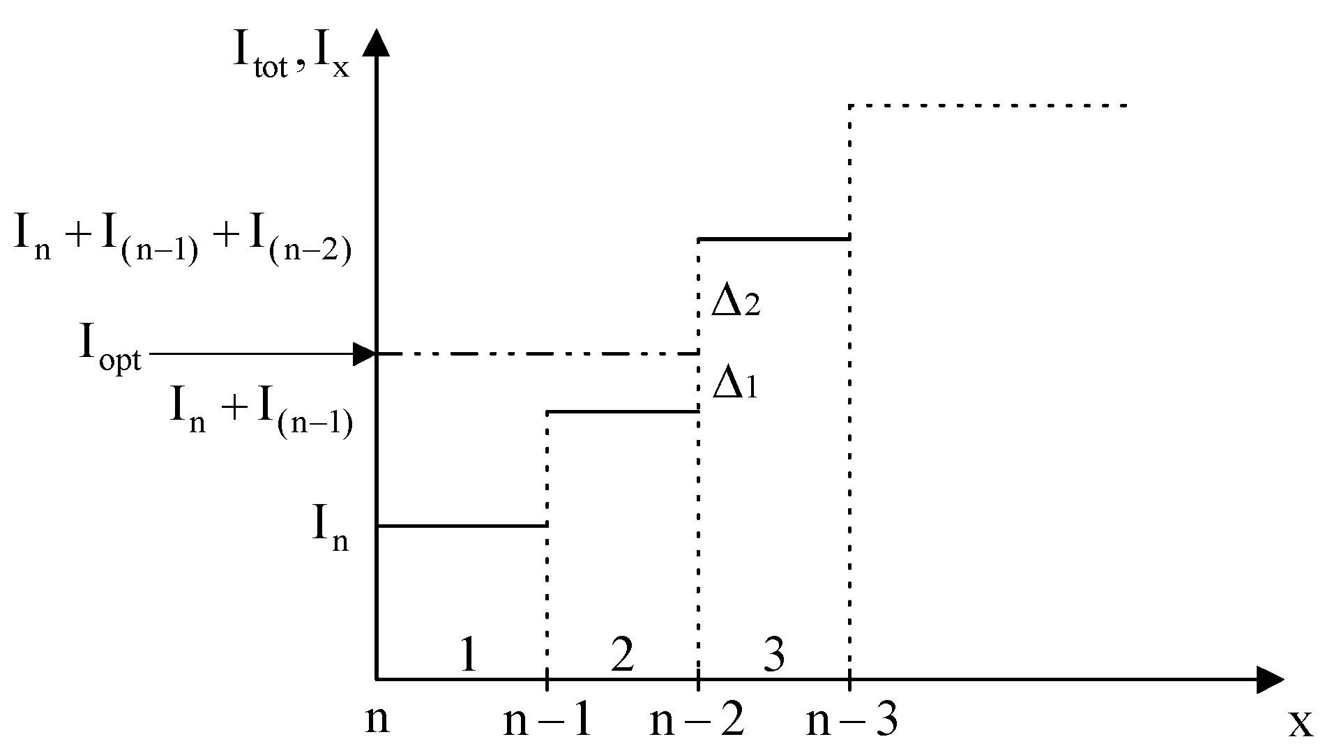
In Figure 2, vertical axis Itot = Ix is the total load transfer. The transfer loads are n and n−1 in Figure 1, i.e., opening section switch No. 2. The total current transfer is I2 = In + In−1, and Δ1 is the current difference between I2 and Iopt. Similarly, Δ2 is the current difference between I3 = In + In−1 + In−2 and Iopt by opening switch No. 3. Since ∆1 < ∆2 in Figure 2, current transfer by opening section switch No. 2 is a better choice.

3. The Fuzzy Index Feeder Switching

Feeder switching is the load redistribution by changing the status of tie switches and sectionalized switches [12,13]. The feasible switching combinations increase exponentially with the number of switches in the system. Formulation of the large-scale mixed-integer combinatorial problem makes it difficult to solve.
To analyze switching operations using fuzzy numerical calculation, two strategies were developed: the tie switch strategy and the sectionalized switch strategy. Combining both strategies can yield an overall strategy to choose the switches for operation.

3.1. Tie Switch Strategy

3.1.1. Large Loss to Small Loss

Define PL(r_i) =     P L ( i _ n ) P L ( i _ m )   = power loss ratio of two feeders connected by switch (i). That is, the power loss ratio PL (r_i) is defined for tie switch (i) connecting two feeder ends n and m, with both feeder losses compared, where
PL(i_n) is the light feeder loss;
PL(i_m) is the heavy feeder loss.
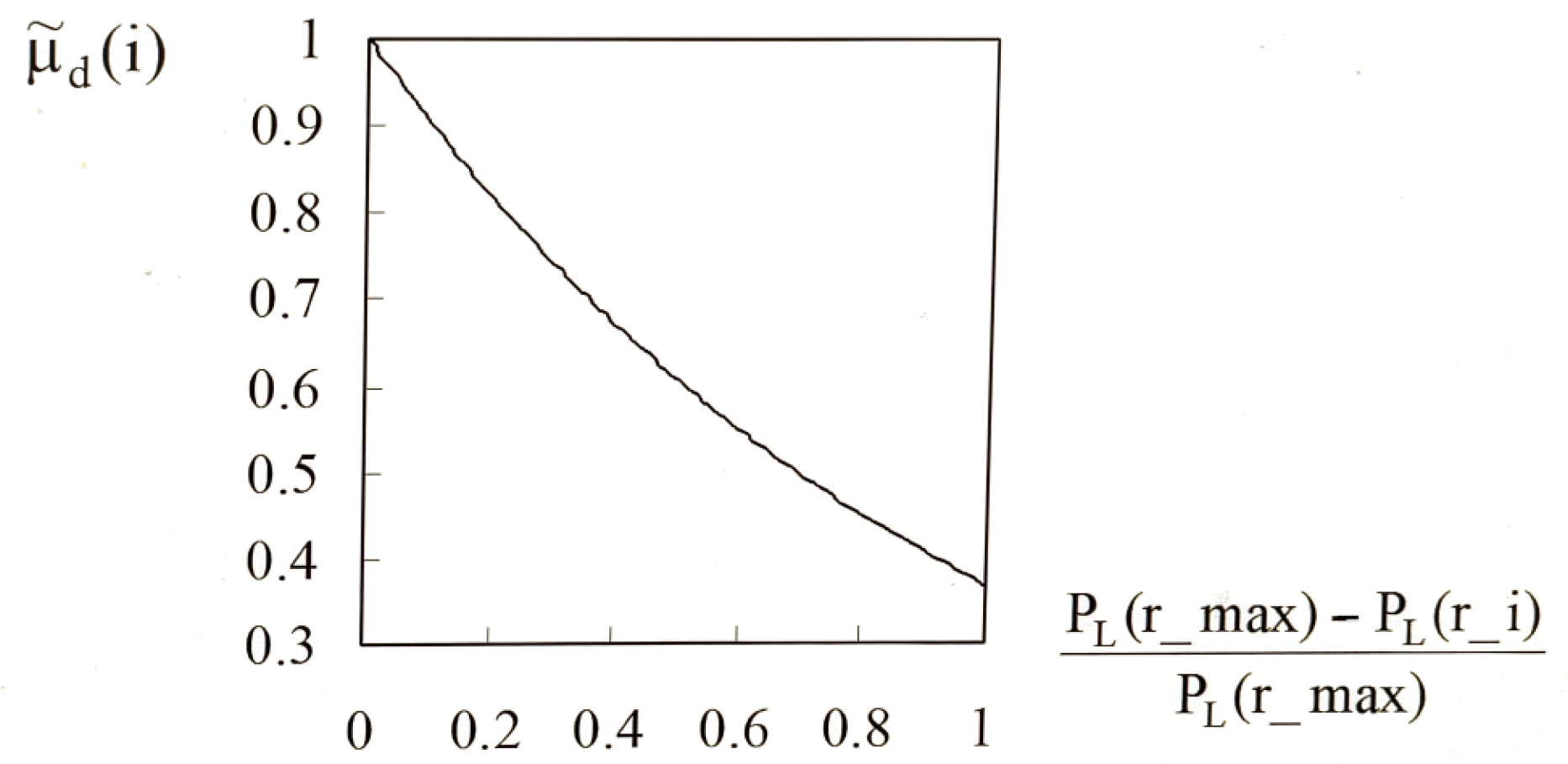
An associate membership function, u ˜ d is defined in (5) and called the “loss severity factor” for calculating the severity of tie switch (i) for transfer, as shown in Figure 3. The term u ˜ d is defined as
μ ˜ d ( i ) =   e     _   [ P L ( r _ max ) -   P L ( r _ i ) P L ( r _ max ) ]   ,   P L ( r _ i )   P L ( r _ max ) ,
where PL(r_max) is the maximum ratio of PL(r_i) among all tie switches {(i)}.

3.1.2. High Voltage to Low Voltage

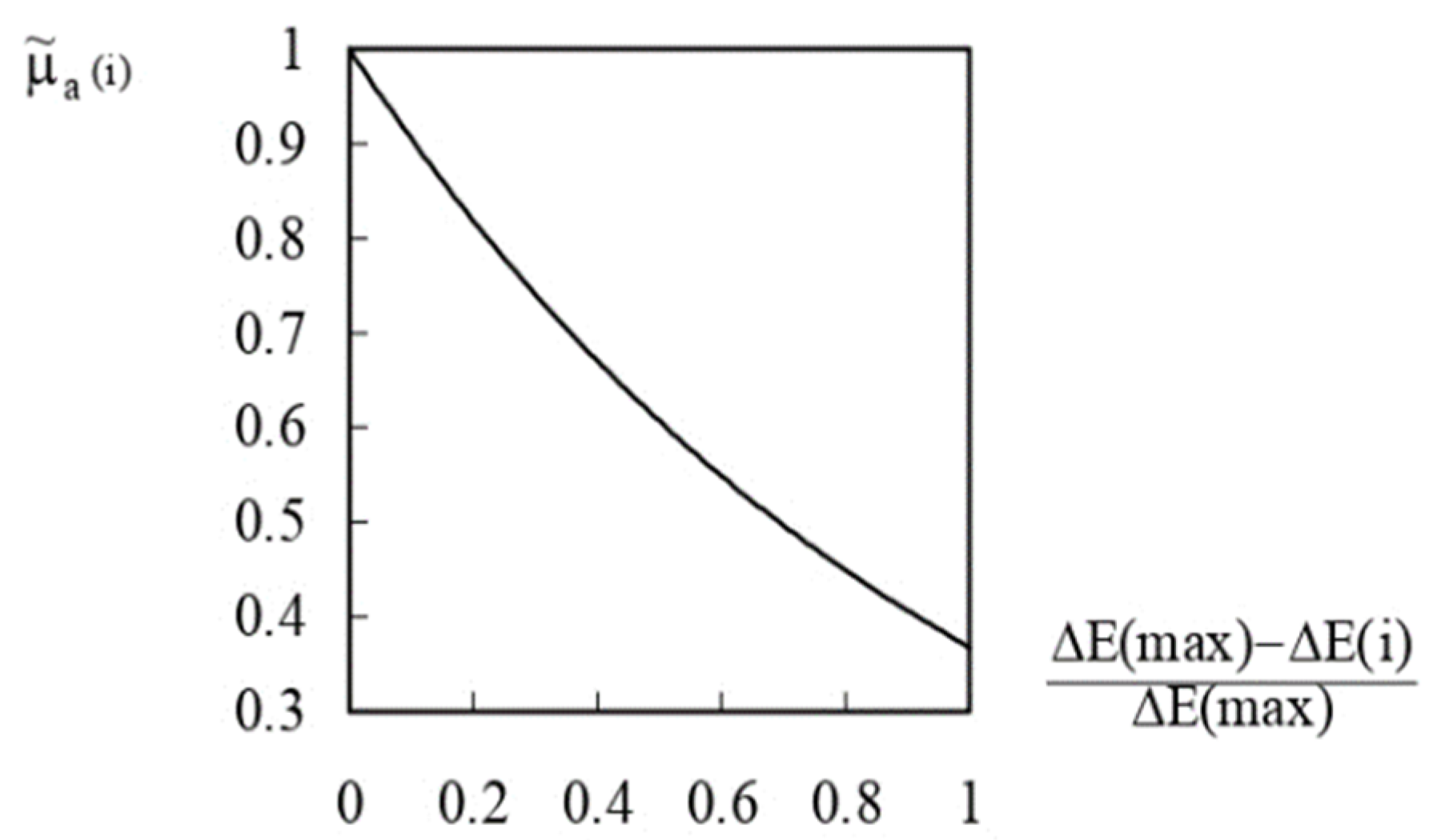
The higher the voltage drop ΔE across the tie switch, the more urgently the power transfer is required. A membership function u ˜ a is defined in (6) as the “voltage indication factor” to calculate the severity of voltage difference ΔE across the tie switch (i). Figure 4 indicates the urgency of needing a transfer. The term u ˜ a is defined by
μ ˜ a ( i ) = e [ Δ E ( max ) Δ E ( i ) Δ E ( max ) ]   ,   Δ E ( i )   Δ E ( max ) ,
where ∆E(i) = En(i) − Em(i) is the voltage difference across both ends of tie switch (i).
En(i) is the end with higher voltage drop;
Em(i) is the end with lower voltage drop;
ΔE(max) is the highest voltage drop among all tie switches {(i)}.
Figure 4. The voltage indication factor u ˜ a (i).
Processes 11 01572 g004

3.1.3. Determination of the Candidate Tie Switch

With the membership functions u ˜ d and u ˜ a, a “tie candidate index” membership u ˜ t(i) can be defined for each tie using
u ˜ t ( i ) = u ˜ a ( i ) × u ˜ d ( i ) ,
u ˜ t ( max ) : max { u ˜ a ( i ) × u ˜ d ( i ) } .
The term u ˜ t(i) shows the need of tie switch (i) to close: the larger the value, the more urgently the tie needs to be closed. The switch with the maximum u ˜ t(max) is the candidate switch.

3.2. Sectionalized Switch Strategy

3.2.1. Calculation of Optimal Load

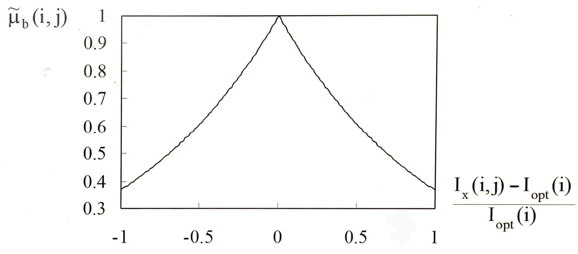
With tie switch (i) selected, the sectionalized switches need to be determined according to current Iopt. For a specific tie switch (i), a membership function u ˜ b(i,j) is defined for the load point (j) as the “optimal current transfer factor” to calculate the closeness of the load (j) transfer current to Iopt. With (i) given, Figure 5 shows the membership function u ˜ b(i,j) of load (j) defined by
μ ˜ b ( i , j ) = e   [ I x ( i , j )   -   I opt ( i )   I opt ( i )   ]   ,   I x ( i , j ) I opt ( i )   , = e   -   [ I x ( i , j )   -   I opt ( i )   I opt ( i )   ]   ,   I x ( i , j ) I opt ( i ) .

3.2.2. The Effect of Excessive Transfer

If the transferred current is greater than Iopt, i.e., transferring the feeder with low current to high current, a negative impact on reducing losses is caused. A membership function u ˜ c(i,j) is defined similar to u ˜ b(i,j) in Figure 6 for the “effect of excessive current switching” to forbid the move by
μ ˜ c ( i , j ) = e w   [ I x ( i , j ) I o p t ( i ) I o p t ( i ) ]   ,   I x ( i , j )   I o p t ( i ) ,
where w is the weighting factor for “over-transfer cut-off control”, and w = 3 could generally forbid Ix (i, j) from being greater than Iopt (i), i.e., forbid the switching operation.

3.3. A Complete Switching Strategy

With all the membership functions defined, we can design the complete switching strategy using the simple value u ˜ s(i,j). That is, a simple rule for decision making with value u ˜ s(i,j) is calculated with operation (i,j).

3.3.1. Transfer for Multiple Feeders

The decision making rules followed the operations below.
If   I x ( i , j )   I o p t ( i ) , μ s ˜ ( i ,   j ) = μ a ( ˜ i ) × μ b ( ˜ i ,   j ) × μ d ( ˜ i ) .  
If     I x ( i , j )   I o p t ( i ) , μ s ˜ ( i ,   j ) = μ a ( ˜ i ) × μ b ( ˜ i ,   j ) × μ c ( ˜ i ,   j ) × μ d ( ˜ i )
We have the decision rule as
μ ˜ s ( max ) = max   {   μ ˜ s ( i , j )   } .

3.3.2. Transfer for Single Feeder

The decision making rules followed the operations below
If   I x ( i , j )   I o p t ( i ) , μ s ˜ ( i ,   j ) = μ a ( ˜ i ) × μ b ( ˜ i ,   j ) .
If     I x ( i , j )   I o p t ( i ) , μ s ˜ ( i ,   j ) = μ a ( ˜ i ) × μ b ( ˜ i ,   j ) × μ c ( ˜ i ,   j ) .
We have the same decision rule as
μ ˜ s ( max ) = max   {   μ ˜ s ( i , j )   }
Single feeder transfer can resolve uneven load distribution among branches and solve the voltage problem. We only need membership functions u ˜ a(i), u ˜ b(I,j) and u ˜ c(i,j). The largest value u ˜ s(max) is the optimal switching solution, such as a multiple feeder.

4. A Layered Feeder Switching Scheme

After switching, a switch pair (i, j) will be found; it is called the solution in the first layer. That is, the remaining tie and sectionalized switch can be reconfigured again to further reduce the loss in a hierarchical or “layered” scheme. The system is re-evaluated to find the new switch pair in a second layer, thus neglecting the switches chosen in the earlier layer.

4.1. For Multiple Feeders

Step 1:
Read system load flow data and compute
PLoss(feeder), ∆E(tie), Ix(bus), Rloop(tie), PL(r_max), ∆E(max);
Step 2:
For layer l, search for the tie switch (i) with (8);
Step 3:
Find a sectionalized switch with (11) or (12);
Step 4:
Find complete switching strategy with (13);
Feeder reconfiguration using the optimal sequence (i,j) and
Step 5:
Execute the load flow program.
If the reconfigured feeder loss is higher, go to the next layer, i.e., l = l + 1 go to step 2.
Step 6:
Repeat until the remaining tie switches are 0.
The load flow is executed for validation after the optimum operation (i,j). It is a great advantage compared with other methods requiring load flow execution or heavy computation at every step.

4.2. For a Single Feeder

Modifying Step 3 using Equation (14) or (15), we get a reconfiguration scheme for a single feeder.

5. Test Results and Discussion

To show the effectiveness of the proposed algorithm, various systems were tested and compared. Three popular examples were used to show the effectiveness. For multiple feeders, two methods were used for comparison:
  • The exhausted search enumeration:
Load flow is executed to evaluate each switching pair (i,j). It guarantees the optimal solution at the cost of large computational resources. It is a very strong case;
2.
del_P loss formula method [2]:
The ΔP change is estimated to evaluate each switching pair (i,j), involving a lot of computation but is more efficient than running load flow. The one with the maximum loss reduction is the solution.
For single feeder reconfiguration, Baran [7] and Goswami [8] were algorithms used for comparison. Algorithms [7,8] have many factors to change and are interesting for comparison.

5.1. Multiple Feeder Transfer

5.1.1. Case 1: A Three-Feeder System

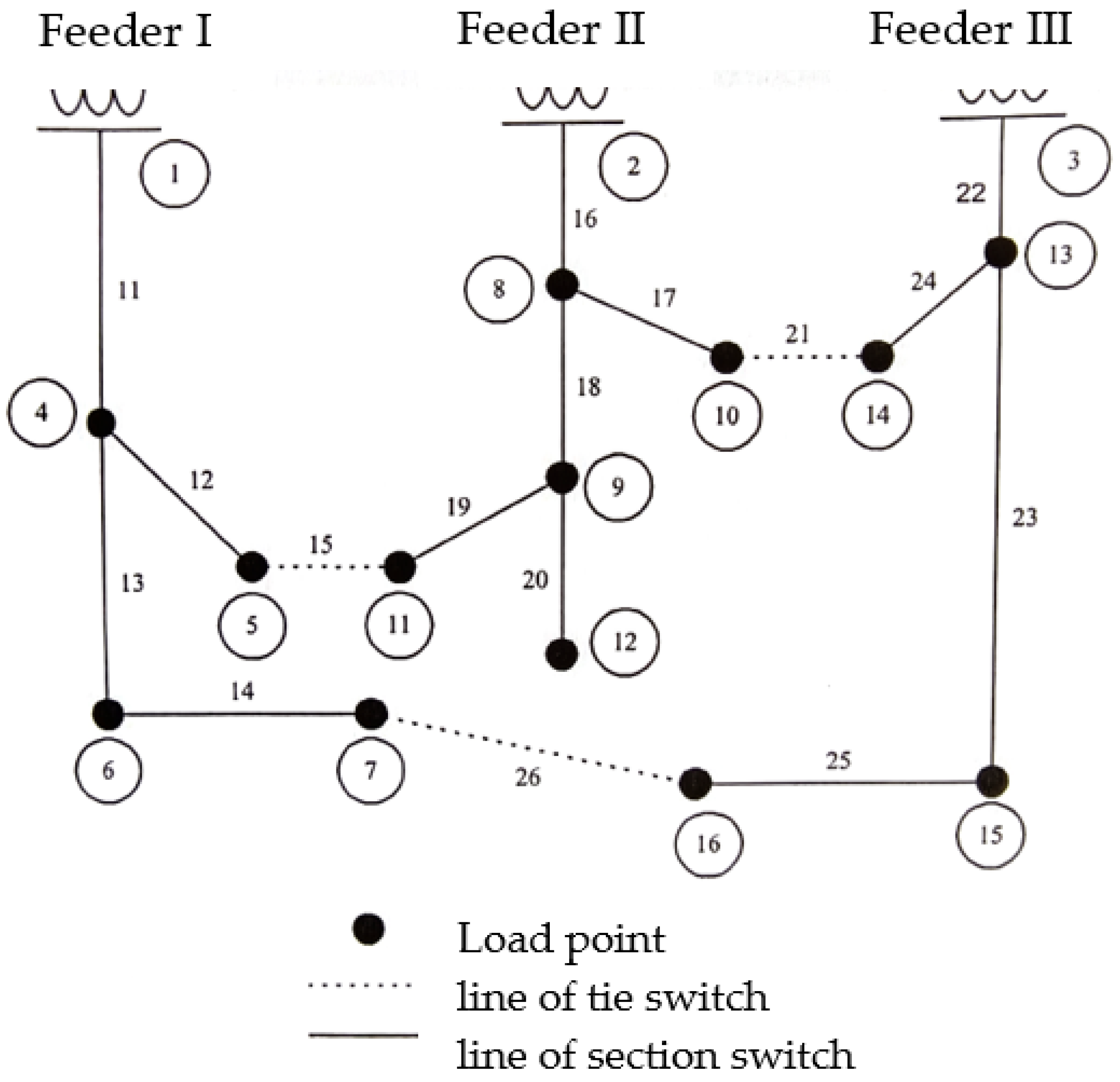
Figure 7 shows a network in [2] with 3 feeders, 13 load points, 3 tie switches (15, 21, 26) and 13 section switches.
In the first layer, u ˜ t (21) = 0.8088 is the largest. Tie 21 is the switch to close, and we can calculate Iopt. Following the calculation, one switch of (16, 17, 22, 24) needs to open. Figure 2 shows the evaluation process and switch 17 is chosen. A similar process follows in all the examples below; u ˜ s (21,17) = 0.4174 is the largest. Therefore, we have a switch pair (21, 17) as the solution to the first layer. Similarly, u ˜ s (15, 19) = 0.423 is the solution to the second layer. Since the third search can no longer reduce the loss, the optimal switching sequences stopped with (21, 17) and (15, 19).
Figure 8 shows the tree path of the optimal solution, including the values of tie switches u ˜ t and u ˜ s for each path. The normally open switches become 17, 19 and 26. For this small system, so-called “optimal” results exist, which are verifiable using the exhausted search. For a large-scale network, we try to find the optimal or sub-optimal solution since there is no way to verify it. Table 1 shows the comparison charts where all three methods yield the same optimal results for this simple network. The proposed method works successfully, as well as the other two methods.

5.1.2. Case 2: Five Feeder System with 33 Switches

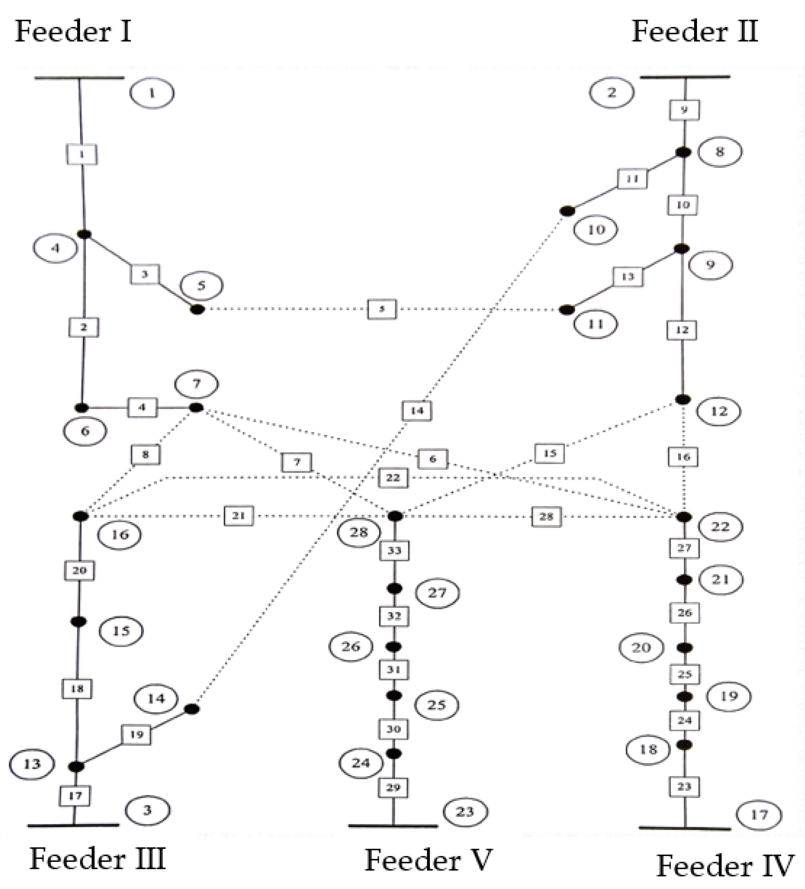
The system configuration of Case 2 can be visualized in Figure 9. There are 5 power sources, 23 load points, 10 tie switches and 23 section switches. Figure 10 shows the tree structure of the process. Each node in the figure represents a possible solution; the thick line represents the chosen path. The figure also shows values of the membership functions.
The simulation results are in Table 2. The first column has the original tie switch numbers. Other columns show tie switches after the reconfiguration with the associated method. It shows that the results obtained from the fuzzy indexing algorithm and the exhausted search are the same, i.e., the “optimal” solution has been found but not the del_P formula. Meanwhile, the fuzzy indexing algorithm used a simple numerical calculation instead of the heavy power flow computation of exhausted search at every stage, showing the effectiveness of the proposed method.
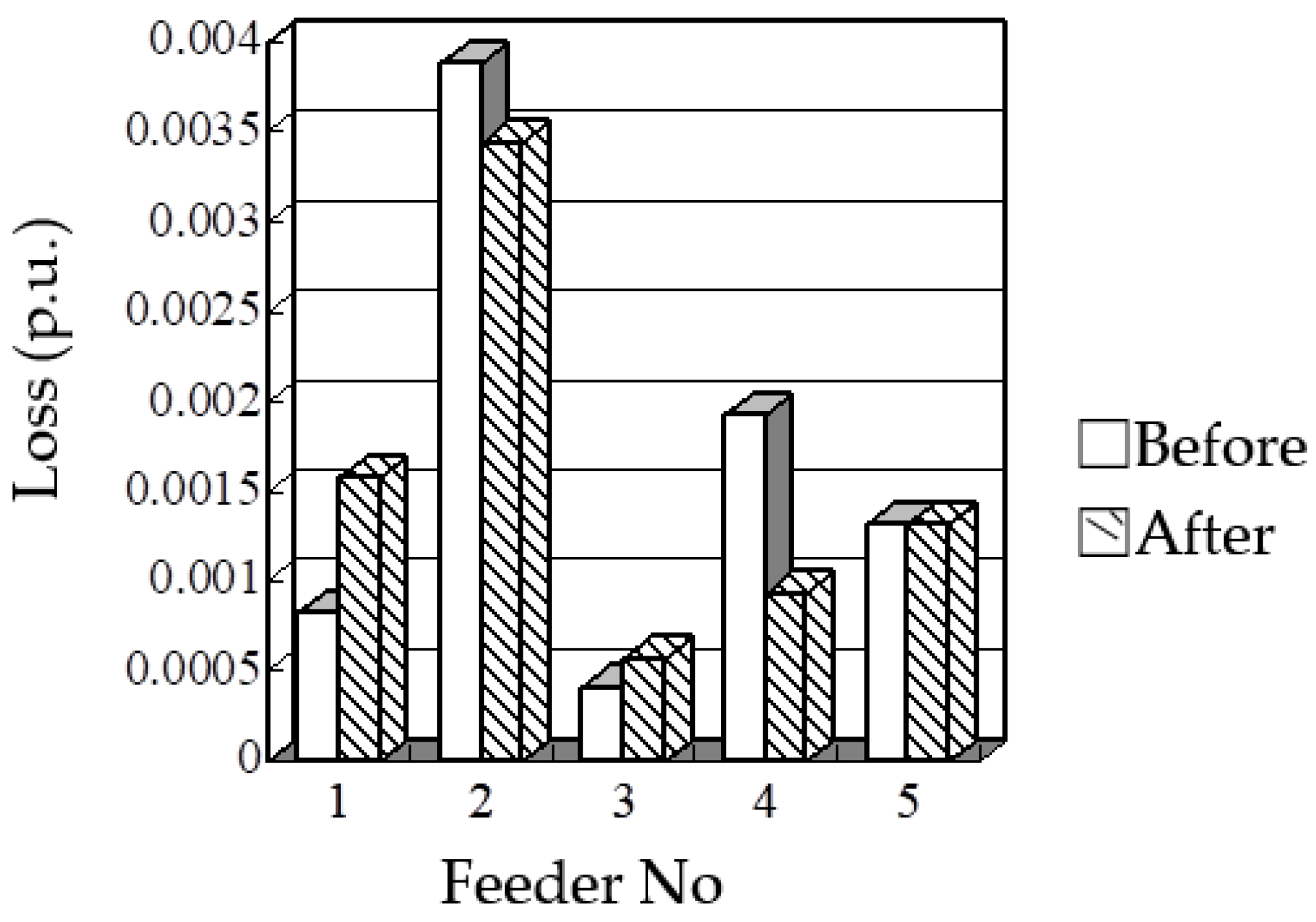
For the optimal solution, the first switching pair (14,11) can reduce the loss by 3.303% and is the most significant, while the second switch pair (6,26) can reduce the loss by 2.801%. The total loss of the system can be reduced from 0.008355 to 0.007845 (p.u.), and the minimum voltage will be increased from 0.969 to 0.971 (p.u.). Figure 11 shows the change in loss per feeder before and after the reconfiguration.

5.2. Single Feeder Transfer

Single feeder switching can solve the uneven load distribution and the voltage problem. Feeder reconfiguration problems solved by Baran [7] and Goswami [8] had many forms and were interesting for comparison.

Case 3: Single Feeder with 37 Switches

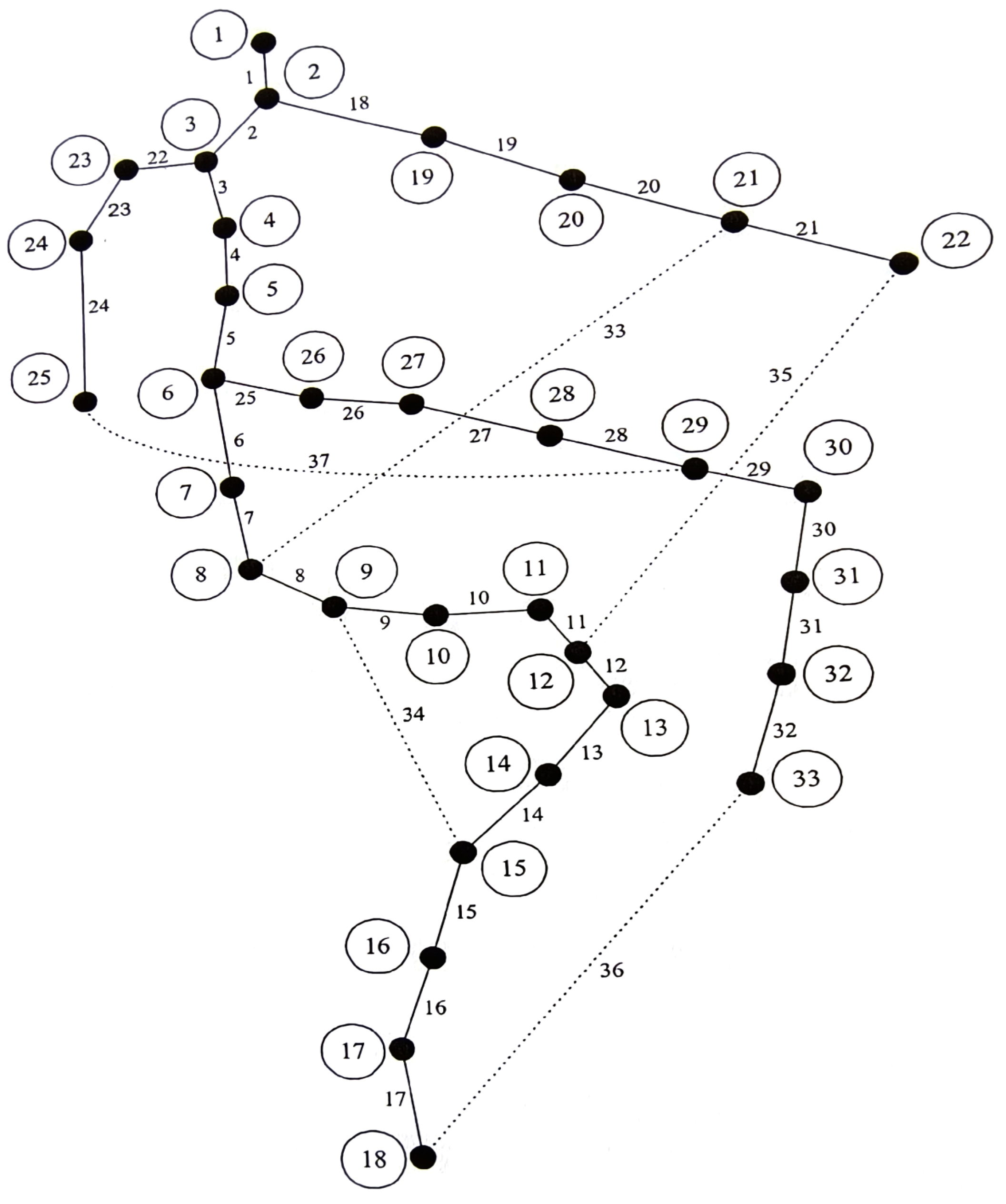
Figure 12 shows the feeder [7,8] with 32 load points, 5 tie switches and 32 sectionalized switches. With the proposed fuzzy indexing algorithm, it takes five layers to obtain the solution.
Table 3 shows the result and the comparison chart with Goswami and Baran. Goswami has three methods: the maximum voltage difference (method I), the minimum voltage difference (II) and the random search (III). As seen from the table, Goswami (I), i.e., the maximum voltage difference, requires seven search layers to get the best results; Goswami (II), i.e., the smallest voltage difference method, also requires seven layers. Goswami (III), i.e., the random search method, follows no rules and was not used for comparison. However, the table used the “best” possibility for method III, although it is not easily attainable. Baran’s results show that after a five-layer search, it can reduce the loss by 27.827%. The fuzzy algorithm requires only five layers to achieve the best results, with a total reduction of 31.148%. Goswami’s can reach the same result, requiring more switching operations than the proposed method. As a switching operation is costly, if three switches are a constrain, fuzzy indexing will be the best choice with 29.352% loss reduction; this is much better than the Goswami and Baran methods.
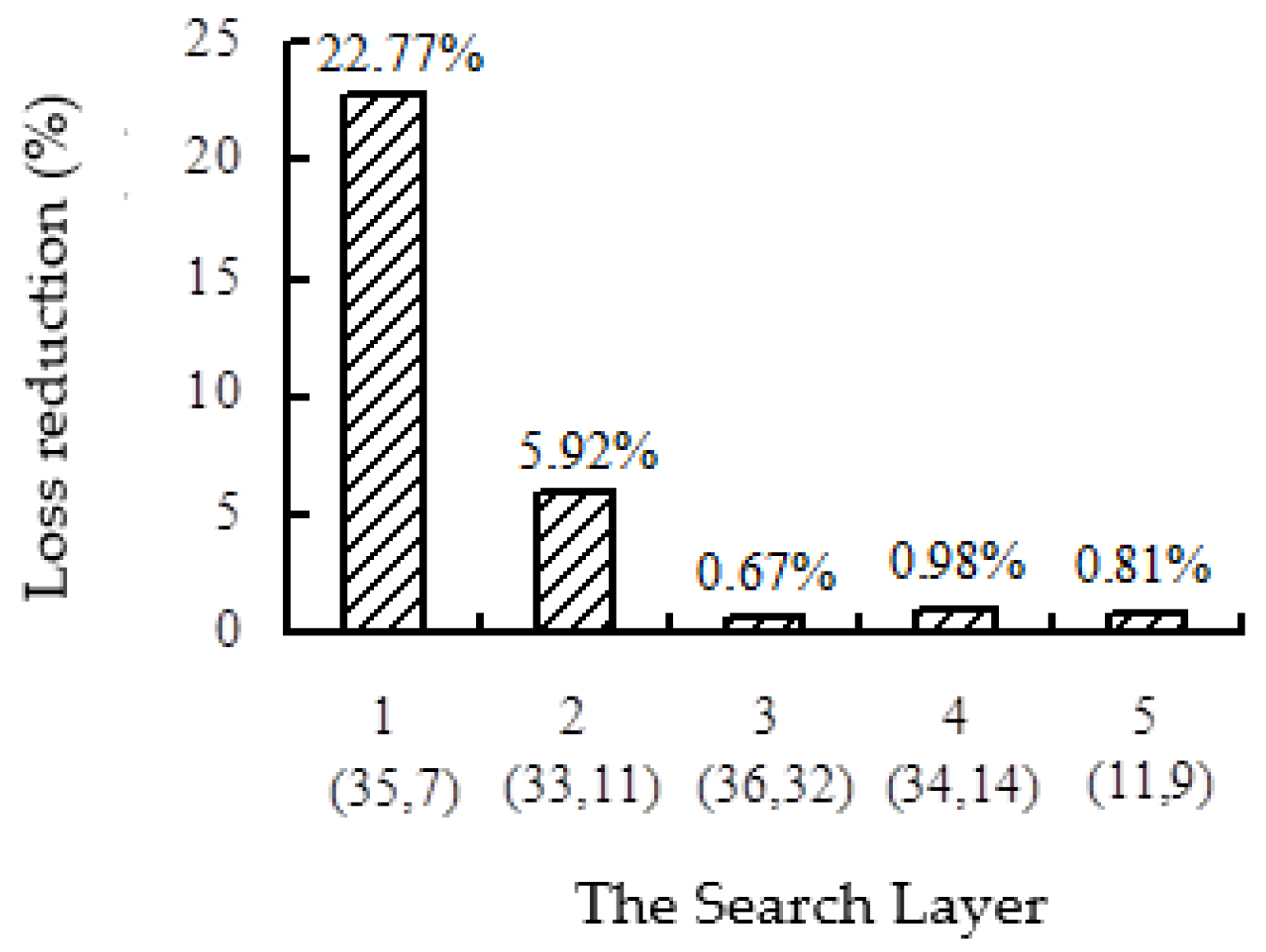
Table 3 also shows the loss reduction percentage for each switching. It shows that the first switching of the proposed method can reduce the loss by 22.77% and has the greatest effect on loss reduction. The “*” sign means no more switching needed.
Table 4 shows the tie switch numbers before and after the switching associated with each method, where the first column has the original tie switches for reference.
In Table 4, Baran (II/III) has fewer switching operations but yields a higher loss. We can also see that the proposed method and Goswami I, II can reach the same reduction, but the proposed method requires fewer switching operations.
The loss reduction in every switching operation of the proposed method is also shown in Figure 13. After feeder reconfiguration, the minimum voltage of the system is also increased from 0.9131 (p.u.) of load point 18 to 0.9378 (p.u.) of load point 32.

6. Conclusions

This paper proposes fuzzy index theory to solve the optimal switching problem and reduce loss. The fuzzy index algorithm used membership functions to simplify the computation, and the solutions were accurate and reliable. There are many advantages to the proposed method:
  • It deals with the large-scale mixed-integer combinatorial problem where conventional techniques would generally fail;
  • The fuzzy indexing simplifies the optimization process with easy numeric calculations instead of large-scale sorting or a large amount of computation;
  • It executes the load flow only once after finding the switch (i,j); this is a great advantage compared with other methods requiring heavy computation;
  • The solution quality is high. It shows that for a small system, the “optimal” results exist and are verifiable by exhausted search. However, for large-scale networks, the solution will be optimal or sub-optimal;
  • The method is suitable for real-time applications even for a large distribution system;
  • It is applicable to all feeder configurations, including the multiple-feeder and single-feeder systems;
  • It can get the best configuration with less switching operations and save on costs;
  • The first switching is the most significant to reduce the loss and balance the load;
  • Proper switching can solve the transformer load management and terminal voltage problems.
More constrains can be added, such as the line rating, voltage limits, and loading limits, together with capacitor banks or DGs for better compensation [21]. With the proposed simple algorithm and test results, the method is effective to implement for either operational or planning purposes.

Author Contributions

W.-M.L. provided the project idea, conceptualization, related experiences, system model, writing and editing. W.-C.T. performed the data curation, analysis and simulations. All authors have read and agreed to the published version of the manuscript.

Funding

This research was funded by Tan Kah Kee College, Xiamen University, grant number JG2021SRF01.

Acknowledgments

The authors want to forward special gratitude to Jun-Zhong Yu for providing the very useful data and materials used in writing this manuscript.

Conflicts of Interest

The authors declare no conflict of interest.

References

  1. Lin, W.M.; Chen, M.S. An Overall Distribution Aotomation Structure. Electr. Power Syst. Res. 1986, 10, 7–19. [Google Scholar] [CrossRef]
  2. Civanlar, S.; Grainger, J.J.; Yin, H.; Lee, S.S.H. Distribution Feeder Reconfiguration for Loss Reduction. IEEE Trans. Power Deliv. 1988, 3, 1217–1223. [Google Scholar] [CrossRef]
  3. Wanger, T.P.; Chikhani, A.Y.; Hackarm, T. Feeder Reconfiguration for Loss Reduction: An Application of Distribution Automation. IEEE Trans. Power Deliv. 1991, 6, 1922–1932. [Google Scholar]
  4. Chen, C.S.; Cho, M.Y. Determination of Critical Switches in Distribution System. IEEE Trans. Power Deliv. 1992, 7, 1443–1449. [Google Scholar] [CrossRef]
  5. Kim, H.; Ko, Y.; Jung, K.H. Algorithm of Transferring the Load of the Faulted Substation Transformer Using the Best-First Search Method. IEEE Trans. Power Deliv. 1992, 7, 1434–1441. [Google Scholar]
  6. Shirmohammadi, D.; Hong, H.W. Reconfiguration of Electric Distribution Networks for Resistive Line Losses Reduction. IEEE Trans. Power Deliv. 1989, 4, 1492–1498. [Google Scholar] [CrossRef]
  7. Baran, M.E.; Wu, F.F. Network Reconfiguration in Distribution System for Loss Reduction and Load Balancing. IEEE Trans. Power Deliv. 1989, 4, 1401–1407. [Google Scholar] [CrossRef]
  8. Goswami, S.K.; Basu, S.K. A New Algorithm for the Recon-figuration of Distribution Feeders for Loss Minimization. IEEE Trans. Power Deliv. 1992, 7, 1484–1491. [Google Scholar] [CrossRef]
  9. Rodrigues, F.M.; de Araujo, L.R.; Penido, D.R.R. Optimization of Reliability through Switch Reconfiguration in Distribution Systems. IEEE Lat. Am. Trans. 2019, 17, 972–982. [Google Scholar] [CrossRef]
  10. Raut, U.; Mishra, S. Power distribution network reconfiguration for loss minimization using a new graph theory based genetic algorithm. In Proceedings of the 2017 IEEE Calcutta Conference (CALCON), Kolkata, India, 2–3 December 2017; pp. 1–5. [Google Scholar]
  11. Nahman, J.M.; Peric, D.M. Optimal Planning of Radial Distribution Networks by Simulated Annealing Technique. IEEE Trans. Power Syst. 2008, 23, 790–795. [Google Scholar] [CrossRef]
  12. Cabana, K.; Candelo, J.E.; Castillo, R. Statistical Analysis of Voltage Sensitivity in Distribution Systems Integrating DG. IEEE Lat. Am. Trans. 2016, 14, 4304–4309. [Google Scholar] [CrossRef]
  13. Tu, H.; Xia, Y.; Iu, H.H.-C.; Chen, X. Optimal Robustness in Power Grids From a Network Science Perspective. IEEE Trans. Circuits Syst. II Express Briefs 2019, 66, 126–130. [Google Scholar] [CrossRef]
  14. Borozan, V.; Rajicic, D.; Ackovski, R. Improved Method for Loss Minimization in Distribution Networks. IEEE Trans. Power Syst. 1995, 10, 1420–1425. [Google Scholar] [CrossRef]
  15. Huang, S.; Wu, Q.; Cheng, L.; Liu, Z. Optimal Reconfiguration-Based Dynamic Tariff for Congestion Management and Line Loss Reduction in Distribution Networks. IEEE Trans. Smart Grid 2016, 7, 1295–1303. [Google Scholar] [CrossRef]
  16. Momoh, J.A.; Ma, X.W.; Tomsovic, K. Overview and Literature Survey of Fuzzy Set Theory in Power System. IEEE Trans. Power Syst. 1995, 10, 1676–1690. [Google Scholar] [CrossRef]
  17. Raj, B.N.; Rao, K.S.P. A New Fuzzy Reasoning Approach for Load Balancing in Distribution System. IEEE Trans. Power Syst. 1995, 10, 1426–1431. [Google Scholar]
  18. Parada, V.; Ferland, A.; Arias, M. Optimization of electrical distribution feeders using simulated annealing. IEEE Trans. Power Syst. 2004, 19, 1135–1141. [Google Scholar] [CrossRef]
  19. Dashtaki, K.; Haghifam, M.R. A New Loss Estimation Method in Limited Data Electric Distribution Networks. IEEE Trans. Power Syst. 2013, 28, 2194–2200. [Google Scholar] [CrossRef]
  20. Díaz, P.; Pérez-Cisneros, M.; Cuevas, E.; Camarena, O.; Martinez, F.A.F.; González, A. A Swarm Approach for Improving Voltage Profiles and Reduce Power Loss on Electrical Distribution Networks. IEEE Access 2018, 6, 49498–49512. [Google Scholar] [CrossRef]
  21. Kumar, P.; Gupta, N.; Niazi, K.R.; Swarnkar, A. A Circuit Theory-Based Loss Allocation Method for Active Distribution Systems. IEEE Trans. Smart Grid 2019, 10, 1005–1012. [Google Scholar] [CrossRef]
  22. Kaneko, A.; Hayashi, Y.; Anegawa, T.; Hokazono, H.; Kuwashita, Y. Evaluation of an Optimal Radial-Loop Configuration for a Distribution Network With PV Systems to Minimize Power Loss. IEEE Access 2020, 8, 220408–220421. [Google Scholar] [CrossRef]
  23. Mahdavi, M.; Alhelou, H.H.; Siano, P. Robust Mixed-Integer Programing Model for Reconfiguration of Distribution Feeders Under Uncertain and Variable Loads Considering Capacitor Banks, Voltage Regulators, and Protective Relays. IEEE Trans. Ind. Inform. 2022, 18, 7790–7803. [Google Scholar] [CrossRef]
  24. Wang, Y.; Xu, Y.; Li, J.; He, J.; Wang, X. Real Time Optimal Reconfiguration of Multiphase Active Distribution Networks. IEEE Trans. Smart Grid 2018, 9, 6829–6839. [Google Scholar]
  25. Lin, W.M.; Chin, H.C. Preventive and Corrective Switching for Feeder Contingencies in Distribution Systems with Fuzzy Set Algorithm. IEEE Trans. Power Deliv. 1997, 12, 1711–1716. [Google Scholar] [CrossRef]
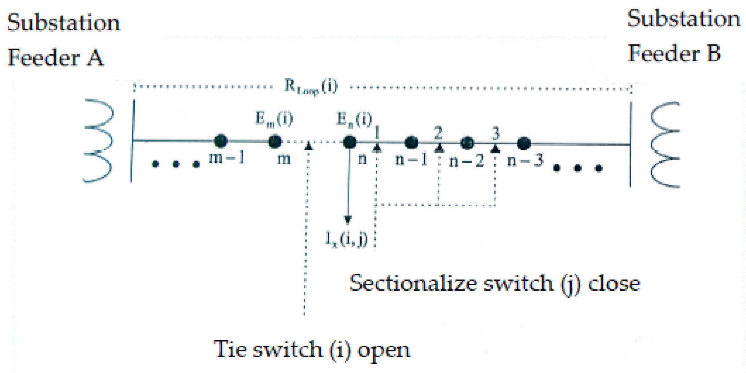
Figure 1. Schematic diagram of a two-feeder system.
Processes 11 01572 g001
Figure 2. Optimal load transfer current.
Processes 11 01572 g002
Figure 3. The loss severity factor u ˜ d (i).
Processes 11 01572 g003
Figure 5. The optimal current transfer factor u ˜ b(I, j).
Processes 11 01572 g005
Figure 6. The effect of excessive current switching u ˜ c(i,j).
Processes 11 01572 g006
Figure 7. A three-feeder distribution system.
Processes 11 01572 g007
Figure 8. The layered switching process.
Processes 11 01572 g008
Figure 9. Five-feeder system with 33 switches.
Processes 11 01572 g009
Figure 10. Tree structure of the five-feeder system.
Processes 11 01572 g010
Figure 11. Loss change in each feeder.
Processes 11 01572 g011
Figure 12. Configuration of the 37-switch feeder.
Processes 11 01572 g012
Figure 13. The loss reduction of each switching layer.
Processes 11 01572 g013
Table 1. Loss reduction for three-feeder network.
LayerOptimal Switch Configurationdel_P Loss FormulaFuzzy Index Algorithm
(on,off)Loss (p.u)Red (%)(on,off)Loss (p.u.)Red (%)(on,off)Loss (p.u)Red (%)
1(21,17)0.0048395.400(21,17)0.0048395.400(21,17)0.0048395.400
2(15,19)0.0046628.860(15,19)0.0046628.860(15,19)0.0046628.860
Table 2. Simulation results of Example 2.
Original
(Tie Switch)
Exhausted
Search
del_p
Formula
Fuzzy index
Algorithm
5,6,7,8,14,15,
16,21,22,28
5,7,8,11,15,16,
21,22,26,28
6,7,8,13,14,15,
16,21,26,28
5,7,8,11,15,16,
21,22,26,28
Action switch(14,11),(6,26)(22,26),(5,13)(14,11),(6,26)
Loss red. (p.u.)0.000510 (p.u)0.000504 (p.u)0.000510 (p.u)
Reduction (%)6.104%6.032%6.104%
Table 3. Simulation results of case 3.
Search LayerGoswami (Method I)Goswami (Method II)Goswami (Method III)Baran (Method I)Fuzzy Index Algorithm
(on,off)Loss (p.u)Red. (%)(on,off)Loss (p.u)Red. (%)(on,off)Loss (p.u)Red. (%)(on,off)Loss (p.u)Red. (%)(on,off)Loss (p.u)Red. (%)
1(35,8)0.0153524.270(37,28)0.0175113.593(33,7)0.0158421.852(33,6)0.0163319.435(35,7)0.0156522.770
2(37,28)0.0147727.107(33,7)0.0158121.976(34,9)0.0157922.104(35,11)0.0145028.439(33,11)0.0144528.686
3(36,32)0.0146227.847(35,11)0.0144328.809(35,14)0.0142229.855(36,31)0.0154423.826(36,32)0.0143229.352
4(34,14)0.0146027.980(34,14)0.0143229.366(36,32)0.0139631.148(37,28)0.0159821.137(34,14)0.0141230.334
5(8,9)0.0144628.666(36,32)0.0141630.121***(6,33)0.0146327.827(11,9)0.0139631.148
6(33,7)0.0140030.935(28,37)0.0141230.334*********
7(28,37)0.0139631.148(11,9)0.0139631.148*********
Table 4. Comparison chart of tie switch numbers.
Original
Tie Switch
Goswami
(I)
Goswami
(II)
Goswami
(III)
Baran.
(I)
Baran.
(II/III)
Fuzzy Index
337771167
3499928119
35141414313114
36323232333432
37373737343737
Number of operations774535
Loss reduction (%)31.148%31.148%31.148%27.83%23.83%31.148%
Disclaimer/Publisher’s Note: The statements, opinions and data contained in all publications are solely those of the individual author(s) and contributor(s) and not of MDPI and/or the editor(s). MDPI and/or the editor(s) disclaim responsibility for any injury to people or property resulting from any ideas, methods, instructions or products referred to in the content.