Article

Air and O2-Assisted Catalytic VACNT Growth Optimization for Uniformity and Throughput

1
CVD Equipment Corporation, 355 S. Technology Drive, Central Islip, NY 11722, USA
2
Chemical Engineering Department, Najran University, Najran 11001, Saudi Arabia
*
Author to whom correspondence should be addressed.
Processes 2023, 11(6), 1585; https://doi.org/10.3390/pr11061585
Submission received: 12 April 2023 / Revised: 12 May 2023 / Accepted: 15 May 2023 / Published: 23 May 2023
(This article belongs to the Section Materials Processes)

Abstract

:
The development of an optimized air or O2-assisted multi-wall vertically aligned carbon nanotubes (VACNT) process that adjusts the vertical height profile of a standard H2O vapor-assisted VACNT process is reported. The effect of the air or O2 chemical vapor deposition (CVD) precursor flow rate, the catalytic Fe layer thickness, the process growth temperature, and the H2/C2H4 ratio on VACNT length was first investigated to find the optimum growth conditions. Spatial distribution height mapping of VACNT structures on six patterned 4″ catalyst Si wafers prepared with a 70–90 min long O2-assisted growth step shows an average growth height of 1.8–2.2 mm, with a standard deviation of less than 10%. Characterization techniques included Raman spectroscopy, scanning electron microscopy (SEM), and spatial height mapping analysis for a range of Fluid channel Array Brick (FAB) components with a length of 30 mm, a width range of 2.5–15 mm, a fluid channel diameter range of d = 5–100 mm, and a fluid channel closest gap range of g = 5–50 mm. A significant finding is that the O2-assisted VACNT growth process optimization efforts enable 2 mm parts processing with square edges, flat top surfaces, uniform height tolerances, and maximum catalyst wafer utilization for application in engineering devices.

1. Introduction

Since its introduction in 2004 by Hata et al. [1] H2O vapor-assisted vertically aligned carbon nanotubes (VACNT) growth, commonly known as the super-growth method for carbon nanotube (CNT) synthesis, is often used to increase the growth rate, catalyst lifetime, and growth height of VACNTs. There has been substantial research into the kinetics and mechanism of VACNT growth [2]. It has been determined that the catalyst-substrate interaction in the tip growth mechanism of VACNT occurs when hydrocarbon decomposes on the metal’s top surface, allowing carbon to diffuse through the metal catalyst, causing CNT to precipitate out across the metal bottom, dislodging the entire catalyst particle from the substrate. As long as additional hydrocarbon breakdown can occur at the metal’s top, CNT will continue to grow vertically. The metal’s catalytic activity declines and CNT growth stops after it is entirely coated with excessive carbon [2,3,4]. The super-growth method has been used, for example, to grow thus far the tallest (up to 21 mm tall) VACNT structures with a specialized catalyst structure on cm-size catalyst wafers [5]. Although Sugime et al. reported a carbon nanotube forest with a length of 14 cm in a 26 h growth step, the carbon nanotubes are not vertically aligned [6]. Odunmaku et al. showed a chlorine-assisted chemical vapor deposition (CVD) method for preparing up to 2 mm multi-wall VACNT, filled with catalyst particles when vapor flow rates were lower than 15 mL/min, as seen in FIG 2B [7]. There is a significant lag between scientific discovery and technological implementation concerning CNTs [8,9,10]. Recently, we used a modified super-growth method to improve the growth height and growth rate for >4 mm VACNT for full-size 4″ catalyst wafers, which we reported in our preceding paper [11], on scaling up the growth of multiple “identical” patterned or non-patterned VACNT structures with a “valley” profile. Similarly, as shown in FIG. 3 and 4 of the paper [12], super-growth-based CNT growth methods generate a VACNT forest structure on a full-size non-patterned catalyst Si wafer with a curved top surface with a distinct concave shape with a steep rise near the edges of the CNT structure. The smaller and taller such super-growth CNT structures are, the more pronounced this top surface “valley” shape effect becomes [5,12]. Also, when multiple small catalyst test samples are distributed along the long axis of a given horizontal CVD process tube over a larger distance, for example, 8″ or 12″, the resulting growth height of these samples is typically not constant. In addition, when the 4″ catalyst wafer is patterned into separated growth regions, the edges of these regions can either roll up or down, thus generating a convex or concave top surface with “steeper” edge curvatures or both roll up and down on a single part, depending on the modified super-growth process conditions and the location of the growth areas within a patterned catalyst wafer layout. These edge effects caused by the super-growth method are most pronounced with taller, ≥2 mm tall VACNT growth height targets and, therefore, typically result in a low component yield when growing many components on full-size catalyst wafers that are positioned in multiple locations along horizontal CVD process tube to increase related component production volume. For some applications that require the top edge sealing ability with a flexible gasket for the finalized components, such top surface distorted components can become non-usable, resulting in a low production yield.
The development of novel, higher-performing nanotechnology-enabled devices for a given target application field that incorporate multiple identical macroscopic parts whose manufacturing process includes a VACNT forest-growth process step, in particular in the mm to centimeter cross-sectional size range, strongly depends on the availability of a cost-effective VACNT forest growth process solution for manufacturing simultaneously many structures that are uniform in height, have minimal edge height distortions, and fall inside a predictable targeted height range. To enable the development of potentially superior VACNT forest growth process step-enabled applications like microelectromechanical systems (MEMS) [13,14,15], there is a need for developing a volume production scalable VACNT growth process solution over the total available surface area of multiple Si wafers that can produce uniformly and repeatably >mm tall VACNT structures with defined properties required to meet all targeted novel part design needs [16,17].
Although air as a process gas additive had already been independently studied by Xuesong Li, et al. [18], where an air precursor gas was used to grow in 15 h up to 15 mm tall CNT bundles at 800 °C with a likely base growth mode on cm-size SiO2 substrates with a typical xylene-ferrocene injection CVD system, the CNT thickness uniformity varied widely (35–100 nm) along the structure’s height with more pyrolyzed carbon added near the top regions of the VACNT. This air-assisted liquid injection VACNT growth method did not provide information on increasing production growth area. Similarly, Zhang et al. [19] showed that an upstream molecular-oxygen-assisted plasma-enhanced CVD process at a growth temperature of 720 °C and pressure of 0.3–0.4 Torr allows the growth of single-wall VACNT structures on full 4″ size wafers with a mixture of 1% of oxygen, 66% methane, 21% Ar, and 12% H2. That paper reports growing single-wall VACNT structures in the 10 µm growth height range over the full size 4″ Si wafer with a 10 min growth time. Sato et al. presented the use of 1 vol% CO2 in comparison to 50 ppmv H2O for the synthesis of mm-tall single wall carbon nanotubes (SWCNT), however, they reported a drop of CNT height from 500 µm along the tube chamber and addressed the importance to optimize the ratio and concentration of hydrocarbon feed gases for the uniform growth of VACNTs over large areas [20]. In a study by Li et al., they first reported the positive effect of CO2 on SWCNT growth via chemical vapor deposition and then found its negative effect on catalyst-particle formation during annealing [21]. Pint et al. studied the effect of oxidant-assisted SWCNT growth using O2, CO2, and H2O and found that trace amounts of O2 result in the lack of any catalytic activity, whereas CO2 and H2O enhance the catalyst lifetime [22]. The authors found that high-temperature growth (∼775 °C) yields the highest-quality SWCNTs, whereas controllable growth of double- and few-walled nanotubes can also be achieved at lower temperatures (550–600 °C). The use of CO as a feed gas had been introduced two decades ago by Tang et al., who used a hot tungsten filament in a CVD for the activation of CO molecules in the synthesis of carbon nanotube structures [23]. Li et al. reported the use of the ethanol-assisted two-zone CVD for the rapid growth of VACNT arrays by setting one zone at 850 °C and the other at 760 °C for VACNT deposition. However, the CNT structure in FIG 2a shows non uniform heights while such structures suffer aggregation, as shown in FIG 8 (a, c, e) [24]. The effect of other CVD parameters on the VACNT aspect ratio had been discussed in detail [25,26,27,28,29]. In this paper, we present our investigation into our novel air or O2-assisted VACNT growth process and CVD system standard process operation for highly uniform 2 mm tall VACNT structures grown simultaneously on up to six 4″ Si catalyst wafers for enhanced throughput inside a relatively simple, atmospheric pressure operated VACNT CVD growth systems. We report here on our process optimization efforts of (1) the air or O2 gas flow rate, (2) the H2/C2H4 ratio, and (3) the CVD process temperature optimization for up to 1.5 h long VACNT growth process step for growing ≥2 mm tall VACNT forest structures.

2. Materials and Methods

For all our experiments discussed here, we used either a small size FirstNano® EasyTube® 2000 with a 3″ outer diameter process tube or a medium size FirstNano® EasyTube® 3000 system with an outer diameter process tube of 5″, SI Figure S1. Both systems had a three-zone motorized clamshell furnace, atmospheric process capability, an automated sample loading capability, and a precursor delivery line connected to a 3-way valve for either Ar or N2 inert gas delivery that connected to a single mass flow controller (MFC) (SI: Automated MFC Range Control). For each system, the precursor delivery line additionally included delivery options with MFCs for H2 (regular tank grade or UHP grade), C2H4 ultra high purity grade (UHP grade), C2H4 (research grade), and air or O2 (UHP grade). For most VACNT process runs, research-grade C2H4, and UHP grade H2 process gas was used, which further allowed to improve the growth height and its reproducibility compared to UHP grade C2H4 and lower grade H2 process gases which showed a daytime-dependent O2/H2O content from sun-heated, outside located gas tanks. In addition, each system was equipped with an air pump and a 500 mL H2O bubbler.
The modified standard operational procedures developed included a Clean Run (SI: Clean Run Process) after each carbon process run and before a new process run after an extended shutdown. Alternating a carbon process run with a Clean Run helped significantly to reduce growth height variation from one process run to the next. The ET 2000 system was additionally modified to include airflow from a filtered air pump to provide sufficient pressure to drive the required airflow through the respective Air MFC. The ET3000 system was modified to include an additional MFC connected to a pressure UHP O2 gas tank to provide the required O2 flow when needed. Additionally, the combined precursor delivery line was always heated to ≥150 °C to prevent moisture accumulation. This further helped to stabilize the modified super-growth VACNT growth method when the H2O vapor precursor flow option was used for some of the tests and to eliminate any leftover moisture from prior super-growth process tests. The relocation of the 1000 Torr pressure sensor, see SI, and the standard operating procedure change of adding a constant gas flow of » 0.5 standard liter per minute (SLPM) of inert gas through the heated precursor delivery line, even when not in process mode, was done to minimize oxygen contamination of the process tube from the pressure sensor line. To minimize air back diffusion through the atmospheric exhaust line, a constant flow of 8 SLPM of N2 was used during the VACNT process run until the process temperature was cooled to below 200 °C.
As further discussed in our previous work [11] all VACNT catalyst wafers were single-side polished 4″ Si wafers, with or without a patterned photoresist layer, onto which a three-layer catalyst film stack (comprised of a 20 nm SiO2 film, a 10 nm Al2O3 film, and 0.5–2 nm Fe film) was deposited in a single batch run with an ebeam system. After loading the to-be-processed samples and closing the endcap of the respective ET 2000 or 3000 system, the system was purged with inert gas so that in 8 min, a total flow of 3× the process volume of the respective process tube was flown to purge most of the air and H2O moisture from the process tube and gas delivery lines. The process tube was then heated in furnace mode under the respective inert gas flow of either Ar or N2 until the center zone process thermocouple reached 10 °C below the targeted VACNT process temperature. Thereafter, the system was switched to cascade temperature control and the set point for the temperature controller for the load zone (LZ), center zone (CZ), and end zone (EZ) got set to the targeted VACNT process temperature. After that, the system was further annealed for 2 min before the process gas was changed to a mixture of inert gas and H2 to deoxidize the Fe catalyst layer and everything was held constant for 3 min. Thereafter, the VACNT growth period started with the flow of the respective precursor gas mixture. When Fluid channel Array brick (FAB) precursors on Si wafers were manufactured with this system, a carbon infiltration process set followed the VACNT growth step [30]. After all the respective carbon processing was completed, the process tube was cooled down by turning off the furnace heating power and by opening the clamshell oven in multiple stages (<750 °C, <500 °C). A mixture of inert and H2 was flown above 2 SLPM into the process tube until the process temperature reached 400 °C to prevent any oxygen back diffusion from the exhaust line. Thereafter only inert gas at the same flow rate was flown until the process temperature was below 200 °C, after which 0.5 SLPM of inert gas was flown through the process tube. The operator then was allowed to offload the test sample by opening the endcap on the manual command. For the ET 2000/ET 3000 system with a 3″/5″ diameter process tube, the optimized VACNT process flow gas was as follows unless otherwise specified below: 1 SLPM Ar/3 SLPM N2, 0.9/3 SLPM H2, 4.1 sccm air/3.0 sccm O2, 1 SLPM, 0.7/2.5 SLPM C2H4, and a constant flow at all times of less than 0.5 SLPM Ar to bypass the H2O to prevent any moisture from getting in there and/or accumulating over time.

3. Results

Initially, a single quartz tray with a single catalyst wafer was used for the first feasibility trials to demonstrate that free-standing VACNT FABs can be manufactured and can survive liquid exposure and subsequent drying without structural changes.

3.1. H2O-Assisted VACNT Growth

An unmodified ET 3000 has been used for these initial trials. SI Figure S2 shows the outcome of such an initial test with a CVD VACNT precursor gas flow rate of 0.5 SLPM N2, 2 SLPM H2, 1.5 SLPM (UHP) C2H4 and 0.75 SLPM of N2 flow into the H2O bubbler heated to 57 °C. The growth temperature was 750 °C, and the growth time was 45 min. The isolated FAB precursors had a fall-off near their edges, with the sharp corners having the most significant drop. This can also be seen more dramatically in the image when looking at the two small-size witness samples from a cut from two non-patterned catalyst wafers made with different ebeam runs, demonstrating that this effect was due to the CVD procedure and not the sample type or ebeam batch. Based on our previous work [11], we expected an upwards curvature for the overall top surface profile. The obtained downwards curvature made it more difficult to seal these convex-shaped parts with a top gasket for fluid flow testing. In addition, the height of these parts often varied from one run to the next (0.5–1.5 mm). This was due to an accidental air leak caused by a degrading O-ring that was used to seal the quartz paddle shaft to the endcap.
We repeated the H2O-assisted super growth test after fixing the detected air leak. During the 70 min multi-wall VACNT growth a 750 °C process temperature was used with these precursor flows: »6 SLPM Ar, »2 SLPM H2, »1.5 SLPM (UHP) C2H4, »0.25 SLPM Ar into H2O bubbler heated to »57 °C. SI Figure S3 shows the resulting FAB height variations measured at the center and 5 mm from the edge of the 30 mm long FABs grow with the specified process conditions. The height dip in each FAB center (opposite to the ones observed in SI Figure S2) was again as expected. This reassured us that ET 3000 system was behaving normally again. In SI Figure S4, three catalyst wafers were processed with 0.5 SLPM of Ar flow into the H2O bubbler. This time a much more significant VACNT height variation, both internal to each catalyst wafer, and from wafer to wafer, was observed, suggesting that the super-growth process was significantly limiting the possible obtainable yields and that possible other process changes might be needed to reduce the edge distortion effects observed and further increase production capacity.

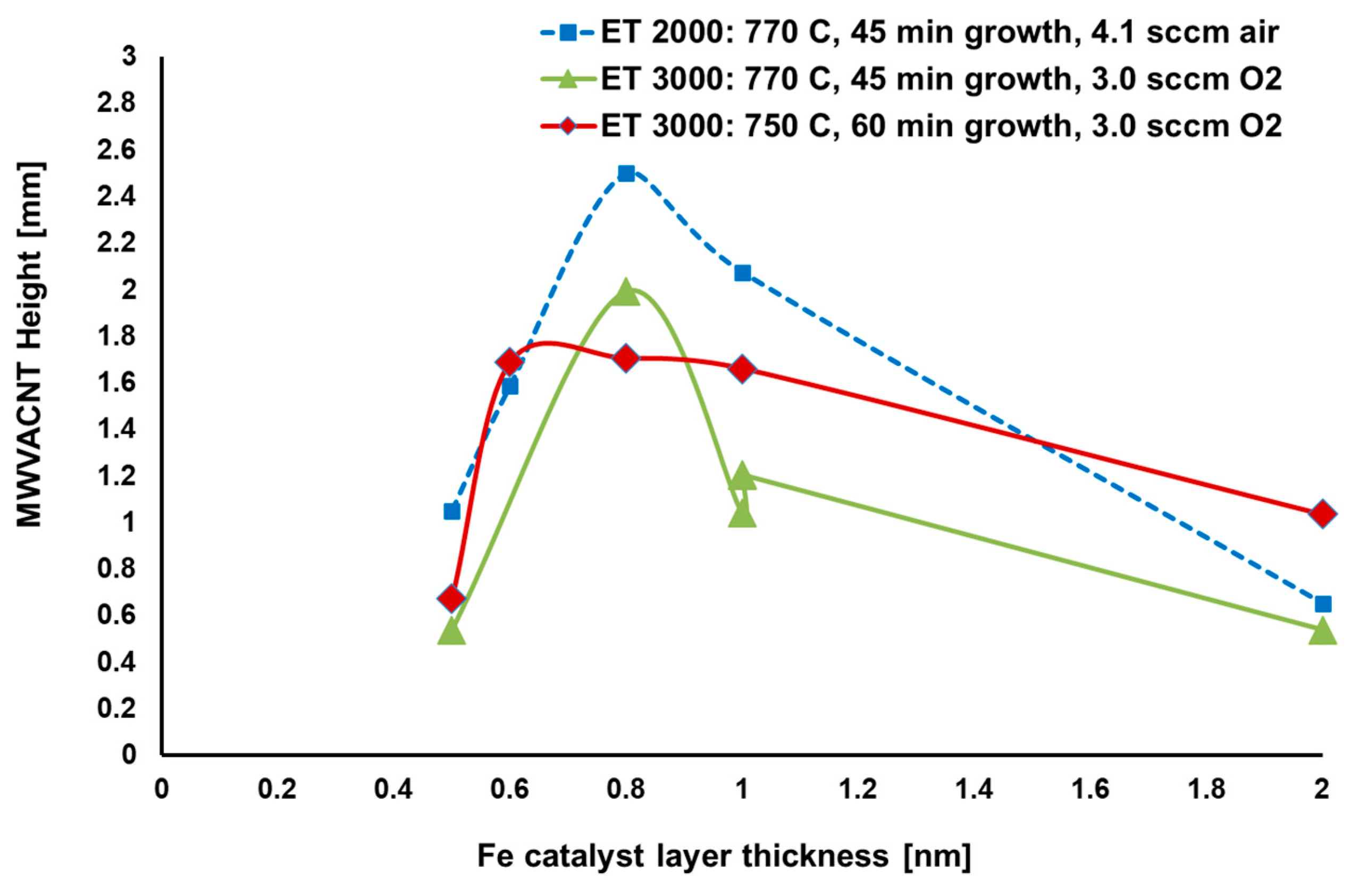
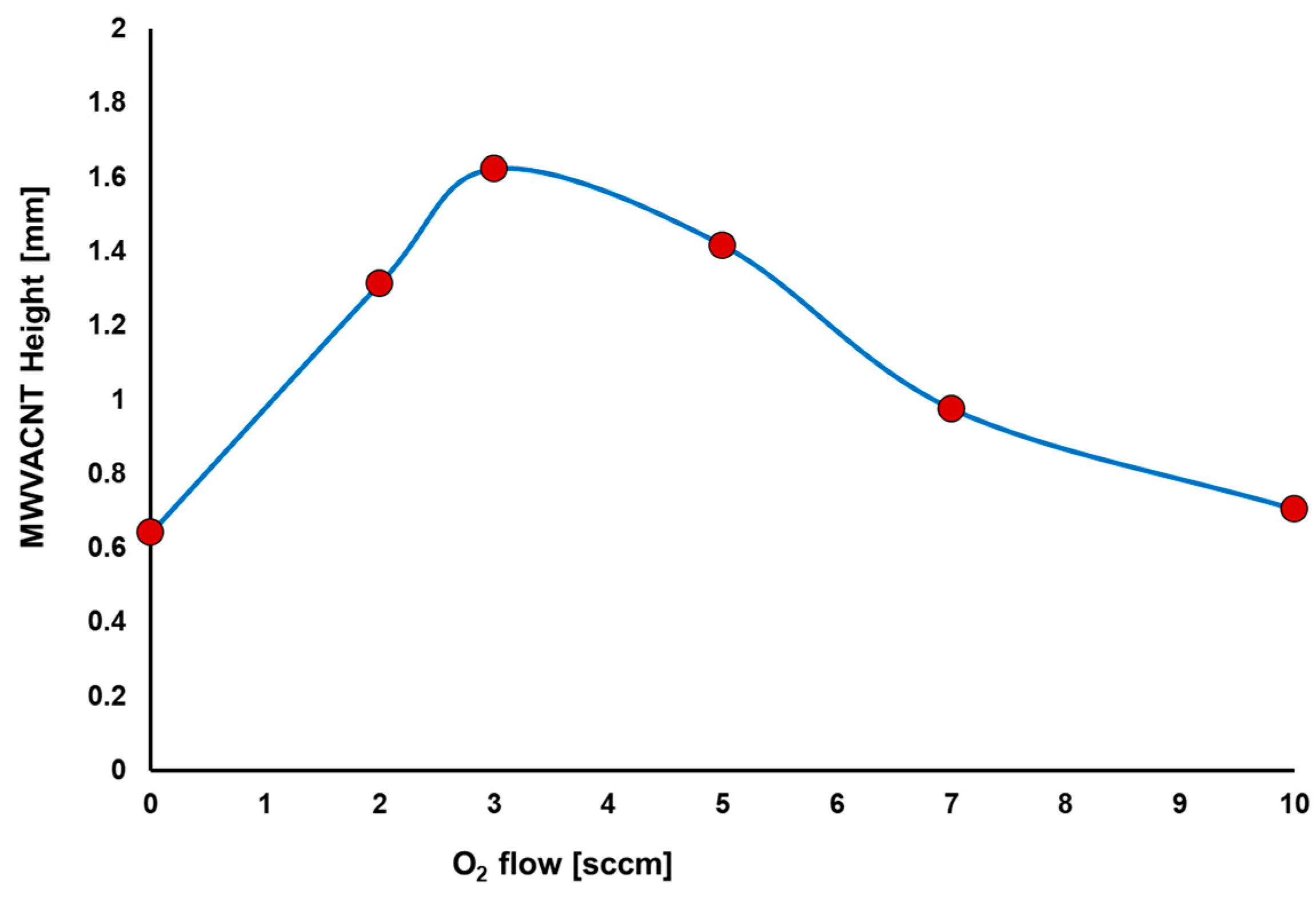
3.2. Air and O2-Assisted VACNT Growth

Before fixing the accidental air leak caused by a degrading O-ring that was used to seal the quartz paddle shaft to the endcap in the ET 3000 system, we tested VACNT growth with no flow in and out of the H2O bubbler with the following precursor flow of » 4 SLPM N2, » 3 SLPM H2, » 2.7 SLPM C2H4 (UHP), and no flow into the H2O bubbler circuit. With 50 min growth time, a similar growth height of 1–1.2 mm was achieved, with a considerable variation from run to run. The result of such a test run is shown in SI Figure S5, which shows much taller and uniform VACNT compared with the H2O-assisted super-growth process. This indicates that O2 might be able to counteract the “valley” shaped top surface of the H2O-assisted super-growth process in the absence of water vapor.
To replace pure H2O vapor with air in the ET 2000 system, we changed the standard operating procedures to minimize any possibility of trapped air or moisture getting into the process tube during the VACNT growth process. To eliminate process variables effects, we used small Si wafer chips from the same catalyst wafer. After some preliminary process dial-in, we settled on a range of process values to be fine-tuned, with all parameters kept fixed, except one, for each test series. There was an observed variation of the VACNT growth height for two cm size samples located in the middle of the 8″ sample holder in dependence on the airflow rate. The presence of air was beneficial for the growth height, with an optimum value near the 4.1 sccm range for the remainder of the process conditions. Also, note that the maximum VACNT growth height obtained with the ET 2000 system was 2.6 mm, Figure 1.
Figure 1 also shows the respective VACNT growth height dependence for the ET 3000 system on O2 flow for samples located at the center of a 4″ quartz tray (center zone) for 5 mm size catalyst square wafer samples for different ebeam runs as well as for reference for the ET 2000 system that had about 1/3.5× lower flow for each process gas, which corresponds to the ratio of the cross-sectional area change between the two systems. Scaling the 4.1 sccm air flow rate from the ET 2000 to the ET 3000 system results in a » 3 sccm O2 flow rate. As Figure 1 shows, with an O2-assisted VACNT process, the VACNT growth height first increases then plateaus off and finally decreases with increasing O2-flow rate. Also notable is that some variations from one ebeam batch to another suggest that further optimization of the ebeam deposition process is needed. Even if the same ebeam catalyst batch (eb1244) was used, the air-assist small diameter ET 2000 system produced better growth than the medium-size O2-assisted ET 3000 system under the tested fixed process parameters. The test results obtained by varying the process temperature at 770 °C, in Figure 2, show the optimum growth height for the tested conditions. Three different positions (beginning (LZ), middle (CZ), and end (EZ)) along the 8″ quart tray were tested simultaneously with cm size catalyst samples from the same ebeam batch run. There was very little growth height variation observed along the 8″ process tube length, with relative height variations increasing with process temperature. The maximum observed growth height for small samples with a 45 min growth time was ~2.7 mm for the ET 2000 system, which is more uniform than a test run with an H2O-based modified super growth process where we observed up to 300 µm height change from one end to the other of the 8″ paddle for some not fully optimized growth process conditions.
Figure 2 shows the growth height dependence on process temperature for both the ET 2000 system at 2.7 mm (at 770 °C) with air or at 1.7 mm (at 760 °C) with O2 and ET 3000 system at 2.0 mm (at 770 °C) with O2. While the ET 2000 system showed a higher growth height with air compared to O2 for the equivalent process parameters, both systems showed relatively similar peak values with O2 at similar parameter values.
Next, we tested the VACNT growth height dependence on the H2/CH4 ratio. Figure 3 shows the observed slightly H2/CH4 ratio-dependent result with a maximum near H2/CH4 = 1.33. Note that a different catalyst wafer batch was used for this test series but with the same targeted catalyst film layer thicknesses of 1.0 nm. The ET 2000 system with air shows a higher growth VACNT height of 2.6 mm compared to a 2.0 mm for the ET 3000 system with O2 for the equivalent process parameters, where both systems show similar trends.
Then we tested the VACNT growth height dependence on the Fe catalyst layer thickness. Figure 4 shows the observed test results suggesting a strong dependence on Fe catalyst layer thickness for both systems.
While a process temperature of 770 °C results in a higher peak growth of ~2.5 mm for the ET 2000 system with air and ~2.1 mm for the ET 3000 system with O2 at 0.8 nm of Fe catalyst layer thickness, the de-rated process temperature of 750 °C results in a much lower process parameters sensitivity, thereby indicating that a de-rated peak process temperature might be a more suitable process parameter for growing uniform growth height over much larger spatial process area, i.e., along a more extended length zone of the respective process tube.

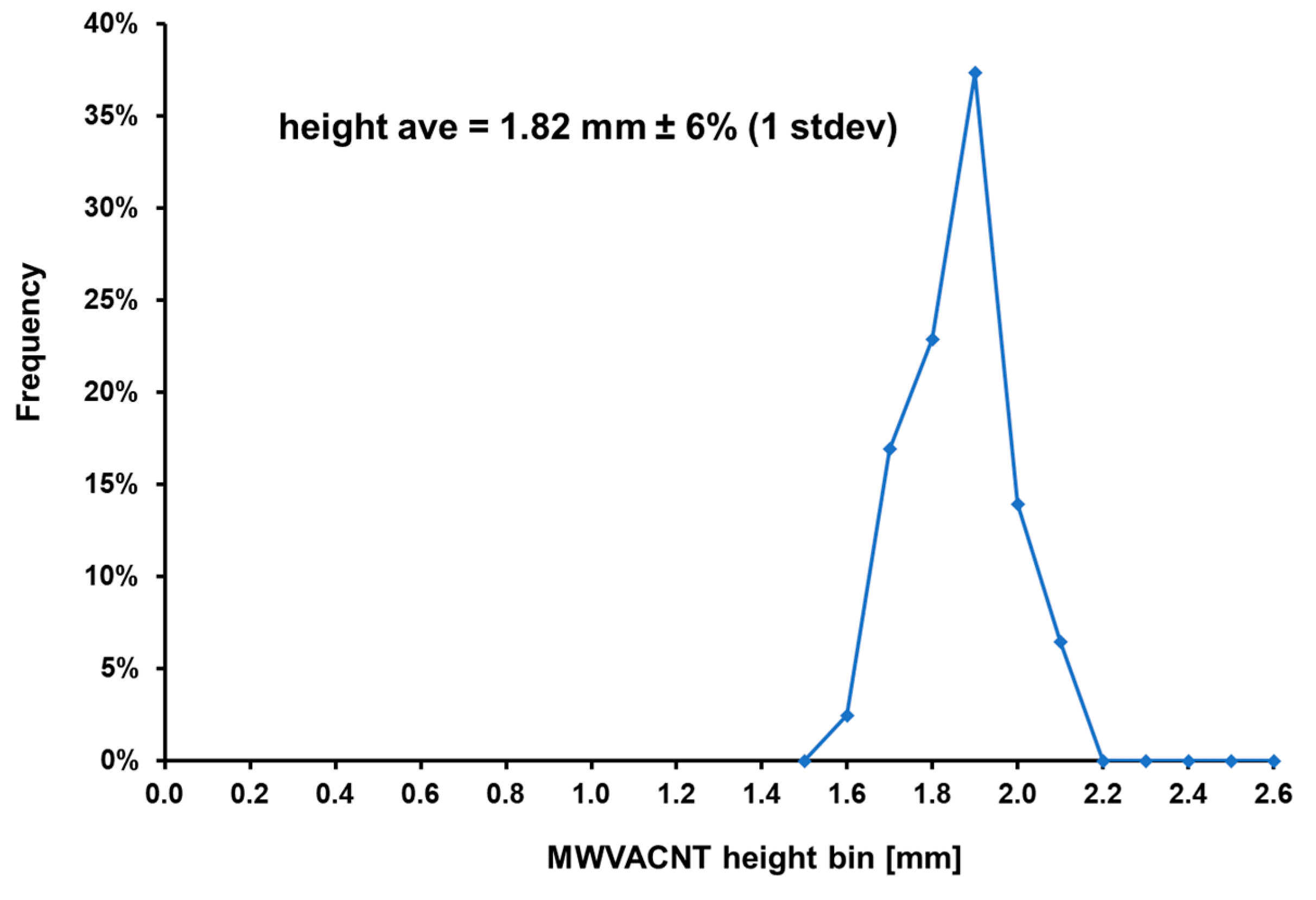
3.3. VACNT-FAB Growth Process Optimization

Initially, a modest target height of 1.2 mm tall VACNT structure inside was set, and two photolithography masks were designed for growing 9 individual 30 mm × 15 mm wide cross-sectional growth patterns with a 2 mm edge exclusion zone and 50 mm or 100 mm fluid channel diameters with a similar gap spacing. The separation between these 9 growth patterns was designed to be about 2 mm to ease further the subsequent removal of the FAB precursors from the growth substrate.
SI Figure S6 shows the results obtained when the optimized (de-tuned) O2-assisted VACNT growth process with an 0.8 nm Fe catalyst layer thickness was used to process the same 12 “long quartz tray holding three 4” catalysts wafers in a row. Note that, compared to the results shown in SI Figure S5, all 9 FAB precursors showed similar and uniform growth height across each part and for all FAB precursors located on the same catalyst wafer. They also showed similar height uniformity from the first to the third catalyst wafer. Also, all the edges of the FAB precursors and the small witness samples were sharp and square, indicating further capacity scale-up potential.
Figure 5 shows a Raman scan of VACNTs grown with the H2O-assisted and the O2-assisted growth processes described above. The Raman scan shows a smaller D/G ratio for the O2-assisted growth process compared to the H2O-assisted growth process indicating that O2-assisted growth is causing a smaller defect level and therefore produces better quality VACNT growth samples.
Figure 6 shows SEM images of VACNT growth with the carbon infiltration process and Fluid channel Array Brick (FAB) components with a fluid channel diameter range of d = 5–100 mm and a fluid channel closest gap range of g = 5–50 mm.
SI Figure S7 shows the mask design innovation where we designed a mask that (i) minimized the spacing between adjacent FAB precursor areas to about <100 µm compared to the original 2 mm gap, (ii) allowed the placement of at least one of the FAB corners up to 3 mm from the catalyst wafer edge (compare to >5 mm before), and (iii) utilized a FAB area gap of <300 µm to grow a sacrificial VACNT in the adjacent unused wafer area. SI Figure S7 shows such a throughput improved mask layout after an O2-assisted growth process that allowed the placement of 11 FAB parts in one version of mask design and later allowed 12 parts, in an optimized version, to be placed on the same 4″ catalyst wafer. As SI Figure S8 shows, the scale up to 12/9 = 133% higher packing did not cause yield losses. Also, these FAB precursors were still subsequently separated without yield loss, even when very tight gap separation was used. This allowed maximization of the usable real estate of a given catalyst wafer size with an optimized mask layout design.
Figure 7 shows the VACNT growth height for full-size wafers with the de-tuned 750 °C process temperature and the optimized Fe catalyst layer thickness of 0.8 nm for 4″ size catalyst wafers. The optimum of 3 sccm for the O2 precursor flow can be seen under the remaining chosen process conditions. Therefore, we used an O2 = 3 sccm flow rate for all subsequent O2-assisted VACNT growth experiments and the Fe catalyst layer of 0.8 nm. (Note that after we rebuilt the ebeam system, we discovered that the quartz crystal monitor position was out of place. After returning it to normal conditions and optimizing the effective Fe layer thickness, we got a new effective optimum Fe layer thickness of 1.2 nm. This shows that for each ebeam-CVD system combination, the Fe catalyst layer thickness must be optimized to the available system.
The histogram shown in Figure 8 shows the narrow height distribution achieved with a ± 6% (1 s) relative height variation across all six wafers, with each FAB component measured in three length locations along the middle axis of each FAB. This confirmed that the developed O2-assisted VACNT process can achieve tight height yields, despite a 600% capacity increase. SI Figure S9 shows the six-wafer’s custom height map shown in SI Figure S8.
After an initial dial-in with a 70 min growth, we determined that the average growth height was on average in the 1.8 mm range, slightly shorter than the targeted >2 mm height range. Therefore, we increased the growth time to 90 min and ran processed photolithographic catalyst wafers with the highest parts density of 12 FAB parts per a 4″ wafer (as shown in SI Figure S8a). This resulted in an average growth height of »2.2 mm with a standard deviation of less than 10% and with a >50% total FAB part yield. The outliers were mostly due to abnormal ebeam batch runs and photolithography batch errors.

4. Conclusions

We optimized an air-assisted, and later an O2-assisted VACNT growth process together with 20 nm thick SiO2, 10 nm thick Al2O3 and 0.5–2 nm thick Fe catalyst layer stack over a Si wafer, first on cm size test catalyst samples and later on single and multiple 4″ Si catalyst wafers, with or without a patterned photoresist film. CVD system modifications and process variations were developed and implemented to maximize process reproducibility by keeping CVD reactor components as dry as possible, minimizing their ability to absorb/release unrepeatable amounts of water vapor (from room moisture) and eliminating any potential source of non-repeatable O2 or moisture release during the process heat up and VACNT growth phase. To further increase process stability, we switched to research grade C2H4 and UHP grade H2 process gases for maximum VACNT growth height stability and used N2 as inert gas for cost reduction. After we optimized the process temperature, H2/C2H4 ratio, Air/O2 flow, and Fe layer thickness first for the few mm to cm size sample, we found that we had to lower the process temperature down from the optimum 770 °C found for both the small and medium size CVD system, to 750 °C to further improve the height uniformity of the targeted components across all size loaded wafers. We also changed from a starting 1.0 nm to a 0.8 nm Fe catalyst layer relative thickness. As a result, the O2-assisted VACNT growth process can now grow flatter, and more height- uniform 2.2 mm VACNT forest structures in a 90 min long O2-assisted growth step, with a standard deviation of less than 10%. Although, we were able to grow 4 mm think VACNT reported in our preceding paper, those VACNT had a significant dip in the height profile across a single 4″ wafer, i.e they had a “Valley“ shaped height profile. The most significant finding of this new paper is that the O2-assisted VACNT growth process optimization efforts enable uniform height growth not only across a single 4″ wafer, but across a 12″ length, i.e 6 4″ Si wafers simultaneously in the 2 mm height range and therefore for the first time allowed high yield VACNT based parts device manufacturing with square edges, flat top surfaces, uniform height tolerances, and maximum catalyst wafer utilization. The utilization of O2-assisted VACNT growth is crucial for achieving cost-effective commercialization of CNT-based devices. Despite the 20-year history of the super-growth method, such an outcome was previously deemed unattainable. The discovery of this approach is poised to significantly influence the manufacturing of VACNT-based devices in the millimeter height range, including FAB devices as detailed in the present study.

Supplementary Materials

The following supporting information can be downloaded at: https://www.mdpi.com/article/10.3390/pr11061585/s1, SI Figure S1. Fully automated small-size FirstNano® EasyTube® 2000 and 3000 atmospheric pressure VAMWCNT growth system with a 3″ and 5″ horizontal quartz process tube.; SI Figure S2. 9 Prototype FAB Precursors spaced by a 2 mm gap in the ET 3000 system grown simultaneously on a single 4″ Si wafer with a modified super-growth MWVACNT progress growth step. Note that each FAB has a height peak near its center of 1.1 mm (convex) and a height roll-off near the 4 edge corners; SI Figure S3. Height map measured every 10 mm on 30 mm long FAB for 9 FAB precursors made after the ET 3000 system was upgraded with a H2O-assisted super-growth process after the air leak was fixed and with all the other upgrades discussed for the ET 3000 systemat at 750 °C with » 6 SLPM of Ar and 0.25 SLPM of Ar flow into the H2O bubbler. Note the 100-200 µm height dip (concave) in the center of all FABs; SI Figure S4. Tilted view of three 9 FAB precursor wafers on a 12″ long quartz tray inside an ET 3000 system. A H2O-assisted super-growth process was used for this experiment at 770 °C, H2/C2H4 = 1.33, Fe = 1.0 nm, 6 SLPM of Ar and 0.5 SLPM of Ar flow into the H2O bubbler. Note the large height variation inside each catalyst wafer and from one to the next wafer; SI Figure S5. 9 Prototype FAB Precursors spaced by a 2 mm gap with edge roll-off for a part center height of 1.1 mm grown simultaneously on a single 4″ Si wafer with a MWVACNT progress growth step without H2O flow showing a convex profile; SI Figure S6. Tilted view of three 9 FAB precursor wafers on a 12″ long quartz tray inside an ET 3000 system. An optimized 70 min O2-assisted MWVACNT growth process at 750 °C was used for this experiment at H2/C2H4 = 1.33, 3.0 sccm O2, and Fe = 0.8 nm; SI Figure S7. Tilted view of three 11-FAB precursor wafers on a 12″ long quartz tray inside an ET 3000 system. An improved mask design tightened the spacing between the parts and added a sacrificial VAMWCNT growth area next to the FAB precursor growth region increasing production capacity at 750 °C, 3.0 sccm O2, and Fe = 0.8 nm. Note the uniform height of the FAB precursors even on their 90 edge corners despite some part corners being only a few millimeters from the edge of the catalyst wafer; SI Figure S8. Uniform MWVACNT growth with standard 70 min long O2-assisted growth in ET 3000 system with custom 6 wafer holder for 12-FAB precursor custom photolithographic mask design: (a) tilted view and (b) side view. Note the uniform growth height on both the top and bottom catalyst wafers; SI Figure S9. Spatial distribution height mapping of 12-FAB precursors (30 mm × 15 mm) on 6 catalyst wafers, each measured at three locations (middle and 3 mm from their long edges). All these wafers were processed with the same 70 min duration O2-assisted MWVACNT growth run that is shown in SI Figure S8. The last wafer was slightly shorter and came from a different ebeam batch run; SI Figure S10. Fully automated large-size CVD Equipment Corporation Carbon+ 300 VACNT growth system with a 14″ horizontal quartz process tube for future volume production scale-up.

Author Contributions

Conceptualization, K.S.; Methodology, K.S. and F.R.; Software, F.R.; Validation, F.R. and K.S.; Formal Analysis, K.S. and F.R.; Investigation, K.S.; Resources, K.S.; Data Curation, F.R.; Writing—Original Draft Preparation, K.S. and F.R.; Writing—Review & Editing, F.R.; Visualization, F.R.; Su-pervision, K.S.; Project Administration, F.R. and K.S.; Funding Acquisition, F.R. All authors have read and agreed to the published version of the manuscript.

Funding

The authors are thankful to the Deanship of Scientific Research at Najran University for funding this work, under the General Research Funding program grant code NU/NRP/SERC/12/13.

Data Availability Statement

The data is available upon request from the corresponding author.

Conflicts of Interest

The authors declare no conflict of interest.

References

  1. Hata, K.; Futaba Don, N.; Mizuno, K.; Namai, T.; Yumura, M.; Iijima, S. Water-Assisted Highly Efficient Synthesis of Impurity-Free Single-Walled Carbon Nanotubes. Science 2004, 306, 1362–1364. [Google Scholar] [CrossRef]
  2. Kumar, M.; Ando, Y. Chemical Vapor Deposition of Carbon Nanotubes: A Review on Growth Mechanism and Mass Production. J. Nanosci. Nanotechnol. 2010, 10, 3739–3758. [Google Scholar] [CrossRef] [PubMed]
  3. Liu, Q.; Shi, X.; Jiang, Q.; Li, R.; Zhong, S.; Zhang, R. Growth Mechanism and Kinetics of Vertically Aligned Carbon Nanotube Arrays. EcoMat 2021, 3, e12118. [Google Scholar] [CrossRef]
  4. Brukh, R.; Mitra, S. Mechanism of Carbon Nanotube Growth by CVD. Chem. Phys. Lett. 2006, 424, 126–132. [Google Scholar] [CrossRef]
  5. Cho, W.; Schulz, M.; Shanov, V. Growth and characterization of vertically aligned centimeter long CNT arrays. Carbon 2014, 72, 264–273. [Google Scholar] [CrossRef]
  6. Sugime, H.; Sato, T.; Nakagawa, R.; Hayashi, T.; Inoue, Y.; Noda, S. Ultra-long carbon nanotube forest via in situ supplements of iron and aluminum vapor sources. Carbon 2021, 172, 772–780. [Google Scholar] [CrossRef]
  7. Odunmbaku, O.; Boi, F.S.; Guo, J.; Lan, M.; He, Y.; Yu, T.; Wang, S.; Xiang, G. Chlorine-assisted synthesis of Fe3C-filled mm-long vertically aligned arrays of multiwall carbon nanotubes. Mater. Res. Express 2019, 6, 015040. [Google Scholar] [CrossRef]
  8. Zhu, Z.; Cui, C.; Bai, Y.; Gao, J.; Jiang, Y.; Li, B.; Wang, Y.; Zhang, Q.; Qian, W.; Wei, F. Advances in Precise Structure Control and Assembly toward the Carbon Nanotube Industry. Adv. Funct. Mater. 2022, 32, 2109401. [Google Scholar] [CrossRef]
  9. Shchegolkov, A.V.; Komarov, F.F.; Lipkin, M.S.; Milchanin, O.V.; Parfimovich, I.D.; Shchegolkov, A.V.; Semenkova, A.V.; Velichko, A.V.; Chebotov, K.D.; Nokhaeva, V.A. Synthesis and Study of Cathode Materials Based on Carbon Nanotubes for Lithium-Ion Batteries. Inorg. Mater. Appl. Res. 2021, 12, 1281–1287. [Google Scholar] [CrossRef]
  10. Shchegolkov, A.V.; Shchegolkov, A.V. Synthesis of Carbon Nanotubes Using Microwave Radiation: Technology, Properties, and Structure. Russ. J. Gen. Chem. 2022, 92, 1168–1172. [Google Scholar] [CrossRef]
  11. Strobl, K.R.F. Water-assisted catalytic VAMWCNT growth optimization for speed and height. Progress 2022. [Google Scholar]
  12. Sugime, H.; Sato, T.; Nakagawa, R.; Cepek, C.; Noda, S. Gd-enhanced growth of multi-millimeter-tall forests of single-wall carbon nanotubes. ACS Nano 2019, 13, 13208–13216. [Google Scholar] [CrossRef] [PubMed]
  13. Barrett, L.K.; Barton, D.J.; Noyce, S.G.; Allred, D.D.; Vanfleet, R.R.; Davis, R.C. High-aspect-ratio metal microfabrication by nickel electroplating of patterned carbon nanotube forests. J. Microelectromechanical Syst. 2015, 24, 1331–1337. [Google Scholar] [CrossRef]
  14. Fazio, W.C.; Lund, J.M.; Wood, T.S.; Jensen, B.D.; Davis, R.C.; Vanfleet, R.R. Material properties of carbon-infiltrated carbon nanotube-templated structures for microfabrication of compliant mechanisms. In Proceedings of the ASME International Mechanical Engineering Congress and Exposition, Denver, CO, USA, 11–17 November 2011; pp. 481–490. [Google Scholar]
  15. Hanna, B.H.; Fazio, W.C.; Tanner, J.D.; Lund, J.M.; Wood, T.S.; Davis, R.C.; Vanfleet, R.R.; Jensen, B.D. Mechanical property measurement of carbon infiltrated carbon nanotube structures for compliant micromechanisms. J. Microelectromechanical Syst. 2014, 23, 1330–1339. [Google Scholar] [CrossRef]
  16. Strobl, K.; GainEy, S.; Kesich, M.; Brogan, J.; Kumar, A. Fluid Reactor and Fluid Reactor Component Manufacturing; World International Property Organization: Geneva, Switzerland, 2021; Volume 046394, pp. 1–96. [Google Scholar]
  17. Strobl, K.; Rajab, F. Long-Lifetime, Superhydrophobic, Free-standing Carbon Infiltrated Vertically Aligned Carbon Nanotube Structures. Surf. Interfaces 2022, 33, 102248. [Google Scholar] [CrossRef]
  18. Li, X.; Zhang, X.; Ci, L.; Shah, R.; Wolfe, C.; Kar, S.; Talapatra, S.; Ajayan, P.M. Air-assisted growth of ultra-long carbon nanotube bundles. Nanotechnology 2008, 19, 455609. [Google Scholar] [CrossRef]
  19. Zhang, G.; Mann, D.; Zhang, L.; Javey, A.; Li, Y.; Yenilmez, E.; Wang, Q.; McVittie, J.P.; Nishi, Y.; Gibbons, J. Ultra-high-yield growth of vertical single-walled carbon nanotubes: Hidden roles of hydrogen and oxygen. Proc. Natl. Acad. Sci. USA 2005, 102, 16141–16145. [Google Scholar] [CrossRef]
  20. Sato, T.; Sugime, H.; Noda, S. CO2-assisted growth of millimeter-tall single-wall carbon nanotube arrays and its advantage against H2O for large-scale and uniform synthesis. Carbon 2018, 136, 143–149. [Google Scholar] [CrossRef]
  21. Li, M.; Yasui, K.; Sugime, H.; Noda, S. Enhanced CO2-assisted growth of single-wall carbon nanotube arrays using Fe/AlOx catalyst annealed without CO2. Carbon 2021, 185, 264–271. [Google Scholar] [CrossRef]
  22. Pint, C.L.; Pheasant, S.T.; Parra-Vasquez, A.N.G.; Horton, C.; Xu, Y.; Hauge, R.H. Investigation of Optimal Parameters for Oxide-Assisted Growth of Vertically Aligned Single-Walled Carbon Nanotubes. J. Phys. Chem. C 2009, 113, 4125–4133. [Google Scholar] [CrossRef]
  23. Tang, Y.H.; Zheng, Y.F.; Lee, C.S.; Wang, N.; Lee, S.T.; Sham, T.K. Carbon monoxide-assisted growth of carbon nanotubes. Chem. Phys. Lett. 2001, 342, 259–264. [Google Scholar] [CrossRef]
  24. Li, Y.; Xu, G.; Zhang, H.; Li, T.; Yao, Y.; Li, Q.; Dai, Z. Alcohol-assisted rapid growth of vertically aligned carbon nanotube arrays. Carbon 2015, 91, 45–55. [Google Scholar] [CrossRef]
  25. Cao, T.T.; Nguyen, V.C.; Ngo, T.T.T.; Le, T.L.; Nguyen, T.L.; Tran, D.L.; Obraztsova, E.D.; Phan, N.M. Effects of ferrite catalyst concentration and water vapor on growth of vertically aligned carbon nanotube. Adv. Nat. Sci. Nanosci. Nanotechnol. 2014, 5, 045009. [Google Scholar] [CrossRef]
  26. Li, G.; Chakrabarti, S.; Schulz, M.; Shanov, V. The effect of substrate positions in chemical vapor deposition reactor on the growth of carbon nanotube arrays. Carbon 2010, 48, 2111–2115. [Google Scholar] [CrossRef]
  27. Li, W.Z.; Wen, J.G.; Ren, Z.F. Effect of temperature on growth and structure of carbon nanotubes by chemical vapor deposition. Appl. Phys. A 2002, 74, 397–402. [Google Scholar] [CrossRef]
  28. Linklater, D.P.; De Volder, M.; Baulin, V.A.; Werner, M.; Jessl, S.; Golozar, M.; Maggini, L.; Rubanov, S.; Hanssen, E.; Juodkazis, S. High aspect ratio nanostructures kill bacteria via storage and release of mechanical energy. ACS Nano 2018, 12, 6657–6667. [Google Scholar] [CrossRef]
  29. Rajab, F. Effect of the chemical vapor deposition process on the aspect ratio of vertically aligned carbon nanotubes (VACNTs). MRS Adv. 2022, 28, 1–6. [Google Scholar] [CrossRef]
  30. Strobl, K.; Gainey, S.; Kumar, A. Fluid Reactors; World International Property Organization: Geneva, Switzerland, 2020; Volume 092816, pp. 1–148. [Google Scholar]
Figure 1. VACNT growth height dependence on the precursor air or O2 flow rate for both ET 2000 and ET 3000 systems, with 45 min growth time at 770 °C, H2/C2H4 = 1.33, and Fe = 1.0 nm.
Processes 11 01585 g001
Figure 2. VACNT growth height dependence on process temperature for ET 2000 and ET 3000 system, with 45 min growth time, H2/C2H4 = 1.33, 4.1/3 sccm air/O2, Fe = 1.0 nm.
Processes 11 01585 g002
Figure 3. VACNT growth height dependence on H2/C2H4 ratio for ET 2000 and ET 3000 system, with 45 min growth time at 770 °C, 4.1/3.0 sccm air/O2, and Fe = 1.0 nm.
Processes 11 01585 g003
Figure 4. VACNT growth height dependence on Fe catalyst layer thickness for ET 2000 and ET 3000 systems with H2/C2H4 = 1.33. Both 750 °C and 770 °C process temperatures were tested for the ET 3000 system.
Processes 11 01585 g004
Figure 5. Raman scans of (a) H2O-assisted and (b) O2-assisted VACNT grown on a catalyst wafer showing less D/G ratio for the O2-assisted growth process, i.e., less CNT damage.
Processes 11 01585 g005
Figure 6. Left: SEM images of VACNT (inset: growth with carbon infiltration process), Right: Fluid channel Array Brick (FAB) components with a fluid channel diameter range of d = 5–100 mm, and a fluid channel closest gap range of g = 5–50 mm.
Processes 11 01585 g006
Figure 7. VACNT height versus O2 flow in ET 3000 system, with 70 min growth time at 750 °C, H2/C2H4 = 1.33, and Fe = 0.8 nm.
Processes 11 01585 g007
Figure 8. Binned histogram of height mapping in 100 µm increments on three locations of each 30 mm long FAB precursor (at the middle and 3 mm from each long edge) for 6 wafers processed as shown in SI Figure S8.
Processes 11 01585 g008
Disclaimer/Publisher’s Note: The statements, opinions and data contained in all publications are solely those of the individual author(s) and contributor(s) and not of MDPI and/or the editor(s). MDPI and/or the editor(s) disclaim responsibility for any injury to people or property resulting from any ideas, methods, instructions or products referred to in the content.

