Article

Development of LoRa Communication System for Effective Transmission of Data from Underground Coal Mines

by
Paul Prasanna Kumar
1,
Partha Sarathi Paul
1,* and
Manjunath Ananda
2
1
Department of Mining Engineering, Indian Institute of Technology (Indian School of Mines), Dhanbad 826004, India
2
Dr. T. Thimmaiah Institute of Technology, Oorgaum Post, Kolar Gold Fields 563120, India
*
Author to whom correspondence should be addressed.
Processes 2023, 11(6), 1691; https://doi.org/10.3390/pr11061691
Submission received: 10 April 2023 / Revised: 3 May 2023 / Accepted: 26 May 2023 / Published: 1 June 2023

Abstract

:
Underground coal mining is a challenging and hazardous occupation that requires constant monitoring of environmental parameters to ensure the safety of miners. A handful of research has been carried out in developing wireless monitoring devices to monitor underground mine workings using Wi-Fi and ZigBee, which has limitations such as limited range, interference, reliability, power consumption, and security. The main objective of this study is to develop an Underground Gas Monitoring Device using LoRa communication for the effective transmission of monitored data. The testing was carried out in an underground mine model to measure the propagation of the LoRa signal with a line of sight and non-line of sight. It was observed that the system performs fairly well in both situations. During testing, it was observed that there was a drop in RSSI at 14 m for non-line of sight, and beyond 17 m no signal was received. Hence, for every 15 m, a booster is required to be placed to maintain efficient and reliable propagation of signals. In the event of an increase in gas level beyond the threshold limit in the underground mine, the developed system actuates the siren in the underground, boosters, and on the surface.

1. Introduction

In many countries, the mining industry, which produces non-metals, metals, and coal, is a significant economic sector. These have a wide range of applications and are important to generate essential elements in a variety of industries, including construction, energy, agriculture, medicine, electronics, and others [1]. Coal, generates around 38% of the world’s electricity and it is also one of the industries with the highest employment levels [2]. Production of coal increased with the increase in coal demand. The sudden increase in production capacity creates a challenging working environment, including an increase in the rate of methane emission in mine workings and carbon monoxide and carbon dioxide gases from the use of diesel engine machinery used to transport coal [3].
The risk increases with the depth of the mine. Therefore, whether mining for coal or any other resource, worker safety should always be a top priority [4]. The toxic gases that are frequently released by underground coal mining operations are difficult for humans to detect [5]. One of the most dangerous industries in the world is coal mining. Underground coal mining is one of the oldest industries and is unsafe among all occupations due to its hazardous and dangerous working environment. This is because of the uncomfortable working conditions and risky environment [6]. Numerous risks, including rock stresses, hazardous gases, dampness, high temperatures, coal dust, silica dust, and specialized equipment, can frequently result in accidents during the coal mining operation. Even worse, the frequency and intensity of these dangers have the potential to have devastating impacts on human life and health [7].
Due to the presence of toxic gases like methane and coal dust, underground coal mine operations have always proven to be extremely dangerous and harmful. According to the statistics, coal dust or methane gas explosions are said to be the cause of 33.8% of fatalities in the mining industry [8]. In the current mining environment, especially in underground coal mines, worker and equipment safety is of utmost concern. One of the most worrying risks in the global coal sector is mining accidents. Many coal miners might die in a single gas disaster. Since the beginning of coal mining, many miners have lost their lives due to gas explosions and gas inhalation. Such events have been a significant problem for employers and employees for a long time. Underground coal mines have the highest number of fatal mining accidents and injuries. Between 2010 and 2021, in underground coal mines around the world, there have been several gas explosion accidents that killed 411 miners, as shown in Figure 1. To prevent any kind of accidents due to gas in mines, a systematic analysis of accidents and their preventive measures must be ensured [9].
Coal mines all across the world are at risk of gas explosions. Reducing deaths and property loss through emergency response is crucial [12]. People may suffocate to death when there is an excessive amount of methane in the air. When the temperature inside a coal mine reaches a certain level, the coal will spontaneously ignite, but because there isn’t enough oxygen there, the combustion won’t be complete and a lot of CO will be produced, which is very attractive to haemoglobin [13]. Methane gas is released during the extraction of coal and when it comes in contact with oxygen at a certain level, they become explosive in nature (Figure 2). The Coward explosive triangle diagram, which Coward and Jones published in 1952, has been accepted as a quick and simple method to assess the gas mixture’s explosibility. In simple terms, three characteristic points define the explosive triangle. The diagram is divided into four distinct zones labeled as the impossible mixing zone, the explosive zone, the not-explosive zone (but could become explosive with the addition of more combustibles or air), and another non-explosive zone. The Coward explosive triangle diagram is shown in Figure 2 [14].
Underground Coal mines are the most hazardous, and the working conditions are often unpredictable. The possibility of disasters increases the risk of coal mining and makes big disasters more likely making it extremely difficult to achieve safety [15]. To increase both security and output in mines, continuous monitoring, and reliable communication must be maintained. Communication is the process of sending signals (or data) to one another in order to exchange information. The necessity for communication in underground mines is important from the perspectives of production and safety. Proper and reliable communication systems not only save machine downtime but also assist in immediately passing messages from the vicinity of the underground working region to the surface for quick rescue operation [16].
Although most of the current monitoring systems for underground coal mines use cable networks as well as wireless sensor networks. The problem with the current monitoring system is—they are unable to deliver the required information at a faster rate in the mines, less bandwidth, limited data transfer, synchronization is difficult, and also the sensors and wires are critically damaged during accidents, especially explosions, and are unable to deliver information for rescue search and detection activities [17]. In order to take the necessary precautions before unexpected events occur, a robust real-time system of gas monitoring is required to be placed in underground, which can communicate the data effectively to the surface via a wireless communication system and helps in taking preventive action. This research aims at developing a gas monitoring device incorporating a wireless LoRa communication system and testing its effectiveness in line of sight and non-line of sight.

2. Related Work

2.1. Existing Communication of Gas Monitoring for Underground Coal Mines

Underground wire communication has a few disadvantages such as it is not useful, reliable, and safe if a cable breaks during a disaster. In hard and humid mining conditions, a wired communication system’s continuity, reliability, and endurance are major concerns. There are dust particles existing in the underground environment due to drilling and other applications [18]. Dust can disturb the regular communication system of mines when it affects a system based on a leaky feeder [19]. The cost of installing a fixed communication system in underground mines is high due to its geographical features. Installing a traditional cable data transmission system in underground mines is very difficult due to ground movement after a roof collapse or an accident [20].
There is also limited research on wireless communication systems using ray tracking technology with the advantages and disadvantages of leaky power line communication systems [21]. Wireless communication systems have a few issues working in underground mines, such as diffraction, attenuation, multipath fading and scattering [22]. Moreover, radiation efficiency predictions for underground mines are examined, and mathematical modelling is used to design a communication system for underground mines [23]. The propagation loss was observed to be significantly associated with the distance between the transmitter and receiver in the drives [24].
Underground mines are considered to be a risky environments where even a small explosion could be harmful. Sometimes the nearby region must be evacuated due to a gas leakage, which may be poisonous in nature. It is crucial to measure the temperature and various explosives gases. Understanding the characteristics of several harmful gases can help avoid a catastrophe. The positioning of various types of sensing element and their appropriate deployment are crucial. The creation and deployment of very compact and inexpensive sensors that have sensing, signal processing, and wireless transmission capabilities have been inspired by recent advancements in wireless communication [25].

2.2. Monitoring of the Underground Mine Environment

The creation of a suitable gas monitoring system is a crucial component of underground mining, which has long been an area of focus on the detection of hazardous gases. The first method to detect the gases involves using human because it seemed to be the only solution. Gas detection methods such as the canary, mice, catalytic pellistors, flame safety lamps, and sensors with cable communication systems have been followed at regular intervals. Currently, electronic sensors in wireless communication systems play an important role in detecting various parameters [26]. Pagers were used in the early stages of wireless communication when information was only available in the radio frequency band [27].

2.3. Communication of Mine Environmental Data for Underground Mine

A Cable Monitoring System (CMS) with a reliable and fast communication network in underground coal mines plays a crucial role in monitoring the surroundings [28]. Cable monitoring system remains one of the existing coal mine safety technologies. Despite the theoretical challenges and decision technique, the problems were previously solved using CMS [29,30]. However, this CMS system has other disadvantages, such as cables that wear out quickly and do not monitor environmental conditions. The cable installation of the cable monitoring system must be expanded as the operating area of the underground coal mine expands, which leads to new installation and maintenance costs. In the event of an accident, especially in the case of a dust or gas explosion, the cables can be damaged, making them unable to transmit the information necessary for rescue operations [31]. As a result, Wireless Sensor Networks (WSN) have recently been crucial in resolving issues faced by the cable monitoring system.
The wireless monitoring system can be deployed at all possible gas collection points, from where efficient data transmission can be achieved by means of boosters placed at regular intervals in underground coal mines. Advances in wireless communication technology have made it possible to transmit data without any loss. The Internet of Things (IoT) contributes a lot as far as safety is concerned [32]. When connected to the Internet, IoT objects exchange data to offer useful services. Short-range wireless technologies like Bluetooth, Wi-Fi, and ZigBee were employed in small-scale networks in the early stages of the Internet of Things, but as IoT services have become more diverse of late, huge networks are becoming more necessary. Although the mining industry still uses Wi-Fi and Zigbee for data transmission, it has some limitations in terms of signal range. In view of getting around the limitations of Wi-Fi and ZigBee, LPWAN (Low Power Wideband Network) technologies like Narrowband Internet of Things (NB-IoT), Sigfox, Category M (CAT-M), Long Range (LoRa), and Long-Term Evolution (LTE), is gaining popularity among service providers. These technologies can be used in large-scale IoT to effectively transmit signals over a wider area. Therefore, wireless monitoring is becoming a sought-after technology among others used in the underground mining industry [33].

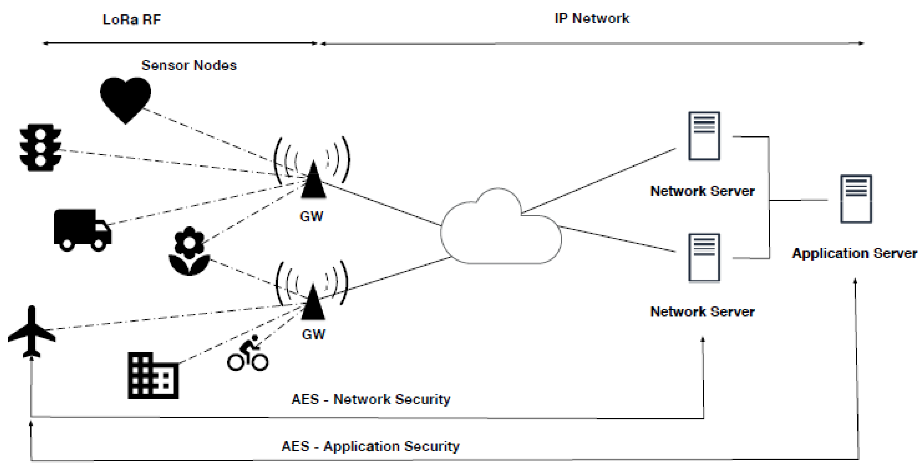
2.4. LoRa and LoRaWAN Operation

For the purpose of optimizing modulation to satisfy range and data needs, LoRa wireless adopts chirp spread spectrum (CSS) modulation with a range of spread factors (SF) and bandwidth options. According to the authorities, LoRa operates on Industrial Scientific Medicine (ISM) frequencies that are separated into channels at 433 MHz, 868 MHz, or 915 MHz. The SF and bandwidth together adjust speed for range [34].
LoRaWAN (a trademark of the LoRa Alliance) includes a protocol stack with wireless LoRa as the physical layer. A LoRaWAN node communicates wirelessly with a gateway containing a receiver hub capable of decoding 10 simultaneous transmissions.
Figure 3 shows the LoRaWAN architecture. The LoRaWAN network’s topology is star-of-stars in terms of its own architecture and is comprised of three primary parts network servers, gateways (GWs), and end nodes. End nodes require gateways (GWs) to connect to the network server (or data server), and communication between GWs and end nodes can be done using either LoRa or FSK modulation over a variety of channels and data speeds. Network servers using classical IP technology manage GWs by receiving data frames from end nodes, receiving them at (GWs), and routing them through the network server [35]. One of the principal aspects of the proposed system is LoRa communication. Among some of the LPWANs that are currently available, LoRa is cheap, robust, low power, and has a range of up to 10 km or more. The LoRa chipset was developed by Semtech. In several nations, LoRa employs Industrial Scientific Medicine (ISM) radio bands [36]. On the surface, the maximum data transmission distance in non-line-of-sight (NLOS) scenarios is 2 km, whilst the maximum distance in line-of-sight (LOS) scenarios is 20 km [37]. Chirped spread spectrum (CSS) and comparable linear broadband-modulated chirping pulses are used in LoRa modulation. A succession of chirps, each of which is a sinusoidal signal whose frequency changes linearly with time, are used to represent every message in CSS. CSS technology can tolerate interference and multipath fading since it uses broadband technology for signal transmission. Also, CSS resists the Doppler effect and chirp ignores signal attenuation. Between the gateway and end devices, a tar topology network is provided by LoRa, a LoRa WAN, a LoRa-based data communication layer, and a physical layer that is based on CSS [38].

3. Materials and Methods

3.1. Features of the System

The proposed Underground Gas Monitoring Device (UGMD) system plays an important role in monitoring mine gases and transmitting information to the surface. As part of this work, a system that continuously monitors the concentrations of O2, CH4, CO, CO2, and H2S, as well as the temperature and humidity in underground coal mines near the work area, was developed. The same data is then simultaneously transmitted to the surface via a long-range (LoRa) wireless communication system. If the concentration of any gas except Oxygen exceeds the allowable limit and the amount of O2 in particular, decreases below the limit as specified by the user, an alarm system is immediately activated in the UGMD, Booster and surface system, and the concerned higher authorities take necessary measures to prevent unexpected situations. The developed UGMD must follow certain guidelines established by the Directorate General of Mine Safety (DGMS). This UGMD system aims to provide continuous gas monitoring through sensors and simultaneously transmit data effectively through a LoRaWAN communication system and enable voice/beep alerts to workers and authorities as shown in Figure 4.

3.2. Hardware Design

The developed UGMD system continuously monitors the concentrations of various gases and simultaneously transmits the data to the surface. If the concentration of any gas exceeds the permissible limit, it immediately triggers an alarm. This functionality is achieved using a microcontroller application. This UGMD system uses teensy 3.2 microcontrollers, which are faster and have a built-in 3.3 V voltage regulator [40]. The Teensy 3.2 is a small development board with a 32-bit 72 MHz ARM Cortex-M4 processor [41]. The Teensy processor has direct access to a USB port to help load code from desktops/laptops to the developed system. All 62 I/O channels can trigger an interrupt and operate at 3.3 V with 5 V tolerance [41]. The developed UGMD has gas monitoring sensors, a LoRa transmitter, a buzzer, an LED, and an SD card connected to the microcontroller, and the surface device has a microcontroller, a LoRa receiver, a buzzer, and an LED. Boosters are connected between the UGMD and the surface system at regular optimized intervals to amplify the signal. Figure 5 displays the architecture.

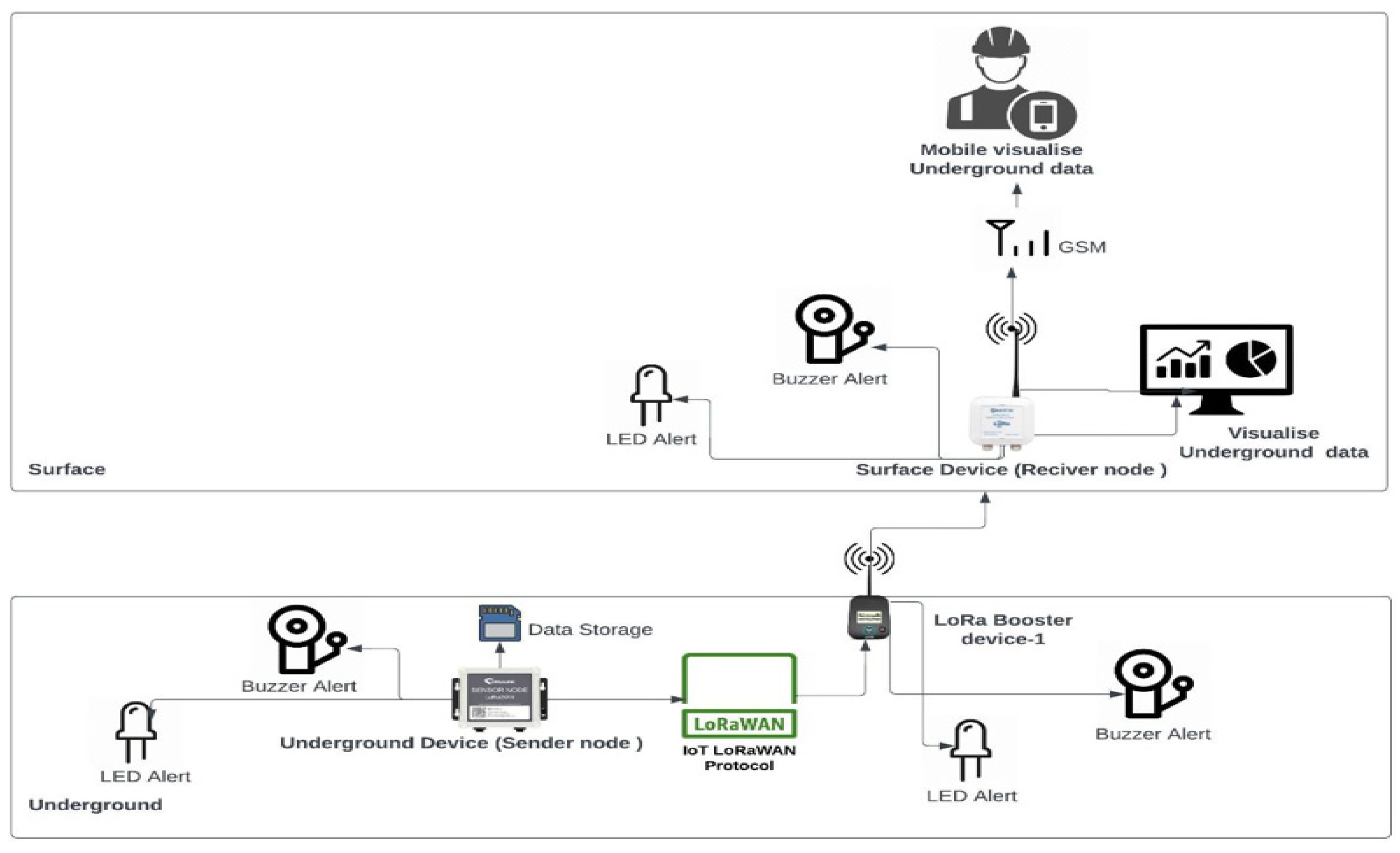
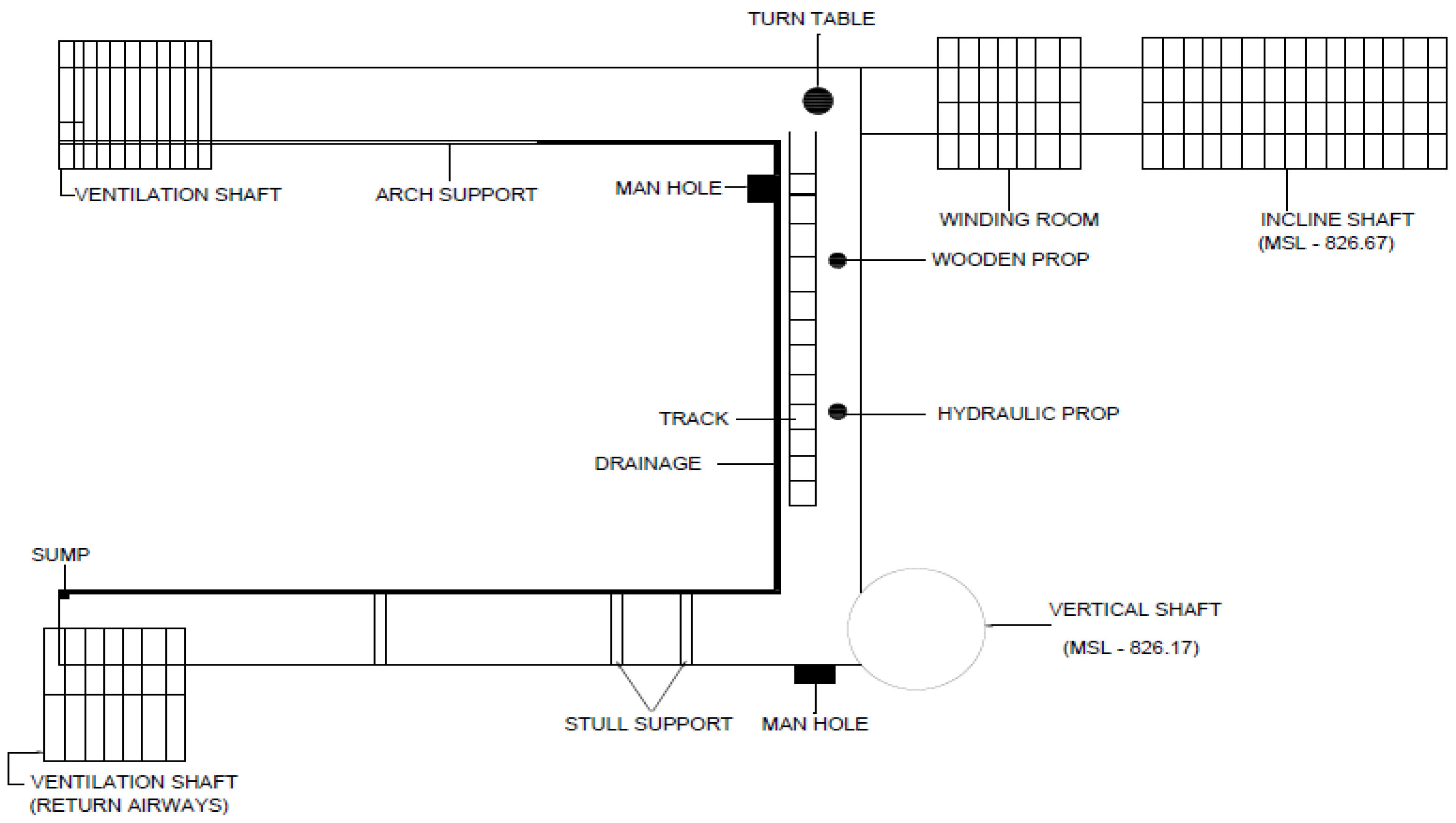
3.3. System Description

The UGMD is designed to detect, monitor, and transmit the presence of a wide range of gas types and their concentrations that can cause gas explosions and toxic oxygen-deficient atmospheres, as well as for early warning of spontaneous combustion outbreaks. The system continuously monitors temperature, humidity, and several gases in the coal mines development and extraction faces, including hydrogen sulphide (H2S), methane (CH4), carbon monoxide (CO), carbon dioxide (CO2), and Oxygen (O2). The monitored data is continuously transmitted by the LoRa transmitter from the UGMD to the LoRa receiver on the surface system. Boosters are used at regular, optimized intervals to speed up the efficient transmission of the signal from underground to the surface. The UGMD monitors and records the increase and decrease of gases like CH4, CO2, CO, H2S, and O2 concentrations respectively, according to CMR, 2017. The UGMD uses a buzzer and LED light to alert underground miners and alert them to the surface near the offices of the Manager, Safety Officer, Ventilation Officer, Fan House, and Rescue Station. The UGMD also has an SD card, so that it can retrieve the gas concentration data of all gases in any unexpected situation and analyze the various reasons for the unexpected situation. The permissible limits for various gases in Indian coal mines are given in Table 1.
The testing of the developed UGMD was carried out in an underground mine model at Dr. T. Thimmaiah Institute of Technology, Kolar Gold Fields, Karnataka, which replicates the actual underground mine. The mine model has one incline access and one vertical shaft of 2.5 m dia and 15 m depth. At a depth of 10 m from the surface, a level has been constructed connecting two parallel drives namely ‘A’ and ‘B’ of 24 m length. One end of the drive ‘A’ is connected to the incline and the other is connected to the ventilation shaft. In the same drive, two ventilation doors and one arch rail support are situated which are made of cast iron. One end of drive ‘B’ is connected to the vertical shaft and the other is connected to the ventilation shaft fitted with an exhaust fan. The drives are supported with various support systems like safari, prop, crossbar, and timber supports. The railway tracks are laid on the floor of drive ‘A’ and the level and the side walls of the mine model are constructed by RR rocks with the width and the height of the underground opening being 2 m × 2 m. Figure 6 shows the Underground Mine Model at Dr. T. Thimmaiah Institute of Technology.
The gases were procured from the gas manufacturer in separate canisters. The capacity of each canister is 0.5 AL which contained 1 kg of gas in compressed form. The gases procured were Methane, Carbon monoxide, Carbon dioxide, Oxygen, and Hydrogen Sulphide with purity of 99.5%, 99.5%, 99.9%, 99.85%, and 99.9% respectively which are shown in Figure 7.
For testing purposes, gases from these canisters were released by pressing the knob slowly and by taking all necessary precautionary measures like connecting a 2 m length hosepipe to the canister outlet to ensure the safety of the operator, wearing a gas protection mask, not allowing people to enter the gas-released zones, etc. The UGMD systems were placed in the underground mine model and on the surface to monitor the normal underground mine environment. The sensors in the UGMD start monitoring the underground mine environment continuously and display the values of each gas and the same values are continuously transmitted to the surface system through LoRa transmitter, where the LoRa receiver in the surface system receives the values and displays the same on the surface system. Information is gathered using WSN in the IoT framework so that devices can interact and communicate with one another without human intervention. The procured gases were released one by one by taking all precautionary measures like wearing a gas protection mask, not allowing people to enter the gas released zones, etc, the proposed system keeps monitoring and displaying the concentration level of various gases. When the underground system records any gas exceeding the specified permissible limits, immediately a RED LED bulb glows with an ALERT HIGH message on LCD display on both UGMD and surface systems. The UGMD system is also embedded with SD Card to store the data continuously, which during any unforeseen consequences will help in retrieving and analyzing the reason for the consequence. Using LoRa, these systems communicate to one another. Several underground mining operations are well suited to LoRa’s data communications capabilities. Therefore, it’s crucial to comprehend LoRa’s propagation properties if LoRa is to be used as a communication method in underground mining. In this study, the results of measurements of LoRa propagation in an underground mine using line-of-sight and non-line-of-sight communication is provided. It is worth to mention that information on LoRa propagation underground is extremely scarce. There have been a very few investigations of LoRa for various industries and only one for the underground mining industry. It is not unexpected that there is only a few research is carriedout using LoRa in underground mining in India because it needs permission from the Directorate General of Mines Safety (DGMS) to take the developed system into mines to carry out investigation and seeking such permission is a lengthy process [43].
All the tests used a LoRa receiver that transmitted and received at 433 MHz. The transmission power of this system is 10 dBm. A LoRa transmitter and receiver equipped with a helical antenna is used to measure RSSI and SNR. In an underground mine model, line-of-sight measurements were taken. The mine model has dimensions of around 2.2 m × 2.4 m. Three measurements were taken across the drive and level with the transmitter positioned at a 2 m height. Three measurements were taken at the outer wall, the centre, and the inner wall as shown in Figure 8.
The receiver was connected to a laptop, and the transmitter was powered by batteries with a 3.3 V output and a 5 V tolerance limit. On the laptop, the data related to gases were shown, and the transmitter and receiver were both connected to the LCD screen. The data is saved on the transmitter’s SD Card, which can be utilized for future investigations during any kind of accident.

4. Results

4.1. Path Loss with the Line of Sight

The average received signal strength index (RSSI) at any given place reduces with an increase in distance, in accordance with the power law of the interval between a transmitter and a receiver. From the transmitting antenna, at distance “d”, the average received power, ‘Pr’, is equal to:
P r   =   P o ( d d o ) n
P r   ( d B m )   =   P o   ( d B m )     10 n l o g ( d d o )
Where “n” is the path loss exponent, and “Po” is the power at a close-in reference point in the antenna’s far-field area close to the transmitting antenna. Assume a forward link where the desired signal is the serving base station and interference is being produced by base stations on the same channel. Typically, the path loss exponent falls between 2 and 4. A higher value of n indicates a larger path loss. The average RSSI over a particular distance can be modelled by specifying the value of n. Nevertheless, the knowledge of the RSSI distribution in a specific range is also required. A lognormal distribution or a dB normal distribution is thought to be a good model for propagation attenuation at a set distance, according to investigated data and theoretical findings [44].

4.2. Exponent of Path Loss

As already stated, the key factor in path loss modelling is the path loss exponent n. When RSSI dB is plotted versus various distances, the path loss exponent is indicated by the slope of the line. ‘n’ is calculated by averaging all measurements made from 1 to 20 m at interval of 1 m. A total of 3 measurements for a spreading factor of 7 at each distance have been taken. It is found that the curve fits well to the straight line and slope of the line is −1.97. Therefore, 1.97 is the exponent of the path loss. Given that the free space path loss exponent is 2, it may be concluded that longer distances in the underground experience less loss than they would in free space. The typical RSSI plotted against distance is shown in Figure 9.

4.3. RSSI Variation Distribution

The RSSI varies at various locations along the drive at the same distance because of the constructive and destructive interference brought on by multipath fading. Diffraction, absorption, and interference are some of the external factors that can affect radio waves and induce changes to the RSSI [45,46,47,48]. This led to the study of RSSI variations over the drive at each distance. In the measurements, a lognormal distribution with a standard deviation of 6.79 dB describes well the variability in RSSI. A histogram of the variation across all samples is shown in Figure 10. These variations were calculated by subtracting the mean of RSSI of the 3 measurements at each distance, from each samples, which resulted in total of 180 samples. The histogram is superimposed on a normal distribution of sample variance calculated from the measurements. It is observed that distribution of the samples is well represented by the distribution of variation.
Quantile-quantile (Q-Q) plots are an additional visualization tool for analyzing the variance distribution across a predetermined distance. A Q-Q plot provides a graphical representation of how well a set of samples fits a distribution derived from the data. Plotting the quantile sets from the sample distribution and derived distribution against one another results in a Q-Q graph. The closer the points to a straight line the better is the match. To put it more precisely a Q-Q plot is a scatter plot, where each pair of data represents a quantile from the observed distribution and a created distribution. The number of sample points and quantiles are normally same. In this situation, samples are used to estimate the mean and variance of a normal distribution. The sampling distribution’s quantiles are shown as a function of the corresponding quantiles of the collective samples. The data are displayed with the mean and variance of the generated normal distribution in Figure 11. The calculated distribution and the sampling distribution are well-matched in Figure 11.
The expected and the observed distribution value follow the same trend as seen in Figure 11. The normal distribution of the sample value is verified using the Shapiro-Wilk test. The p-value of the Shapiro-Wilk test is 0.0593 suggesting that the values are normally distributed, and the null hypothesis is accepted. It is also observed that the RSSI variation within the underground mine model has a standard deviation of 6.79 dB.

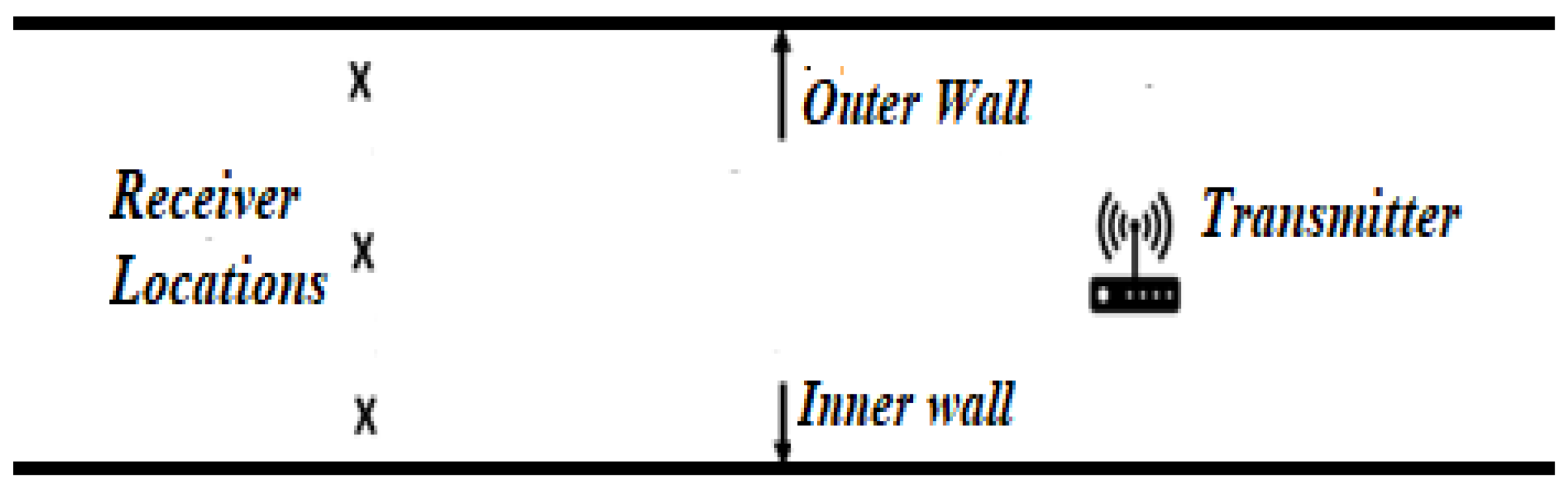
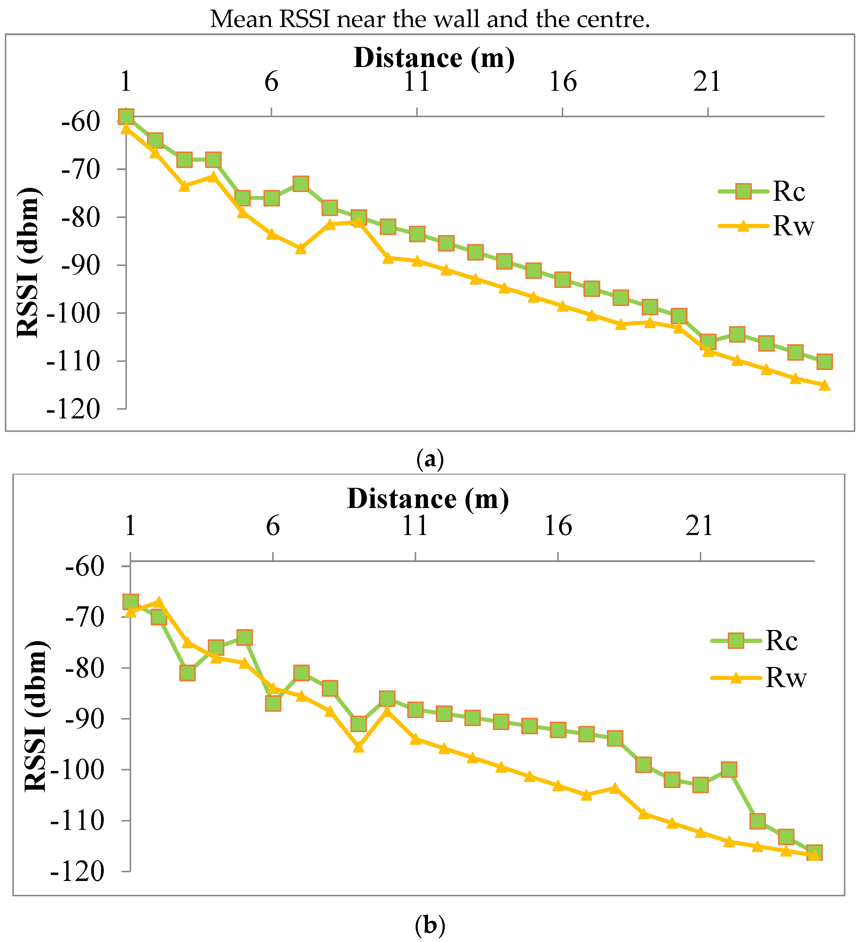
4.4. Effect of Receiver Position within Underground Mine Model on RSSI

The effect of the position within the mine model must be determined. To do this, two groups of analytical measurements are created: those near the wall and those at the centre. For each distance, 3 measurements were made across the drive at 0.3 m from the outer and inner walls and at 1.1 m from both walls forming the centre of the drive. The average of each measurement at each distance was then calculated. The average RSSI is shown in Figure 12 both at the centre and near the wall.
From Figure 12a–c, when the distance between the transmitter and receiver increases, it is seen that the RSSI tends to decrease and in between, there are some variabilities in the RSSI because of the presence of rough surfaces, bulges of the drive and because of the interference of the metal arch supports and metal doors. For the transmitter placed at the centre of the drive, the RSSI was observed for all three positions i.e., either side of the wall and at the centre of the drive as shown in Figure 12a. For the transmitter placed on the outer and inner sides of the wall, the RSSI was measured for the three positions of the drive as shown in Figure 12b and Figure 12c respectively. Figure 12a–c were compared to determine the best location for the receiver and the transmitter in the drive. It was found that the signal attenuation is lower when the receiver and transmitter is at the centre as compared to when it is near the walls.

4.5. Signal-to-Noise Ratio

The signal-to-noise ratio (SNR) for LoRa transmission at 433 MHz can vary depending on special transmission conditions, such as transmitter-receiver distance, antenna gain, and ambient noise level. However, LoRa is designed to operate in noisy environments and can provide reliable data transmission even with a very low signal-to-noise ratio [49]. According to Semtech, a leading manufacturer of LoRa technology, LoRa can provide reliable data transmission even in environments with SNR as low as −20 dB. In order to achieve great tolerance to interference and noise, LoRa uses a patented spread spectrum modulation technique. LoRa also makes use of forward error correction (FEC), and data rate and transmission power can be adjusted based on the distance between the transmitter and the receiver according to adaptive propagation parameters [50]. Throughout the experimental work, while measuring RSSI between transmitter and receiver, SNR was ranging between 9–9.5 dB, which is within the specified range.

4.6. LoRa without a Line of Sight

Two different sets of tests were carried out to better understand the signal propagation properties for non-line of sight. To investigate the impact of the transmitter and receiver positions on RSSI for non-line of sight, the transmitter location was fixed in the first set, i.e., the transmitter was located 2 m from the junction and by placing it in the centre of the drive. The RSSI and SNR were measured first by placing the transmitter 2 m from the junction and covering the full length of the level with an interval of 1 m for a distance of 24 m. At each point, the receiver was placed at 3 different points as shown in Figure 13.
In the second set, to be aware of the short-range consequences near the drive and level junction, the transmitter position was changed to the centre of the drive at 2 m, 4 m, and 6 m from the junction towards the drive end. For each position of the transmitter, RSSI was measured at three points (one at the centre & two near the walls in the level) between 2 m to 24 m from the junction at 1 m interval. In this study, measurements were taken with the transmitter placed at the center of the drive by placing receiver along the inner and outer walls and at the center of the drive.

4.7. Effect of Position for Non-Line of Sight on RSSI

Testing was conducted by positioning the transmitter and receiver at different location places i.e., near the walls and at the centre and at different distances i.e., at 2 m to 6 m from the junction and it was observed that beyond 13 m, the signal was not received. From Figure 14, it is also clear that RSSI is better at the centre of the level than near the walls.
Identifying the range of signal in non-line of sight was one of the objectives of this research. It also aimed to determine how the receiver’s signal intensity changed depending on its location (near the wall and in the centre), as well as how far it was from the junction. The results reveal that the signal reaches a distance of 13 m for a non-line. The readings of RSSI observed at distance of 14 m to 17 m remains almost constant for the receiver placed at the center. The RSSI readings were undetectable for distance beyond 13 m in case of receiver placed near the wall as shown in Figure 14. The above results suggest that the receiver should be positioned at the center of the drive for better signal transceiving in non-line of sight. The transceiving beyond certain distance was not expected due to the LoRa sensitivity (−120 dBm).

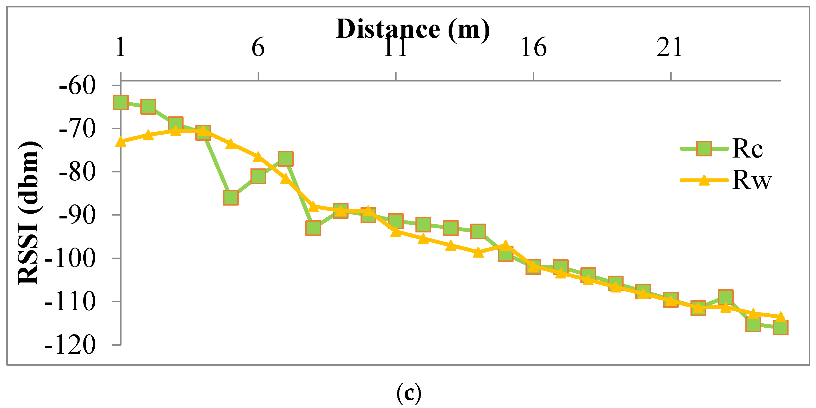
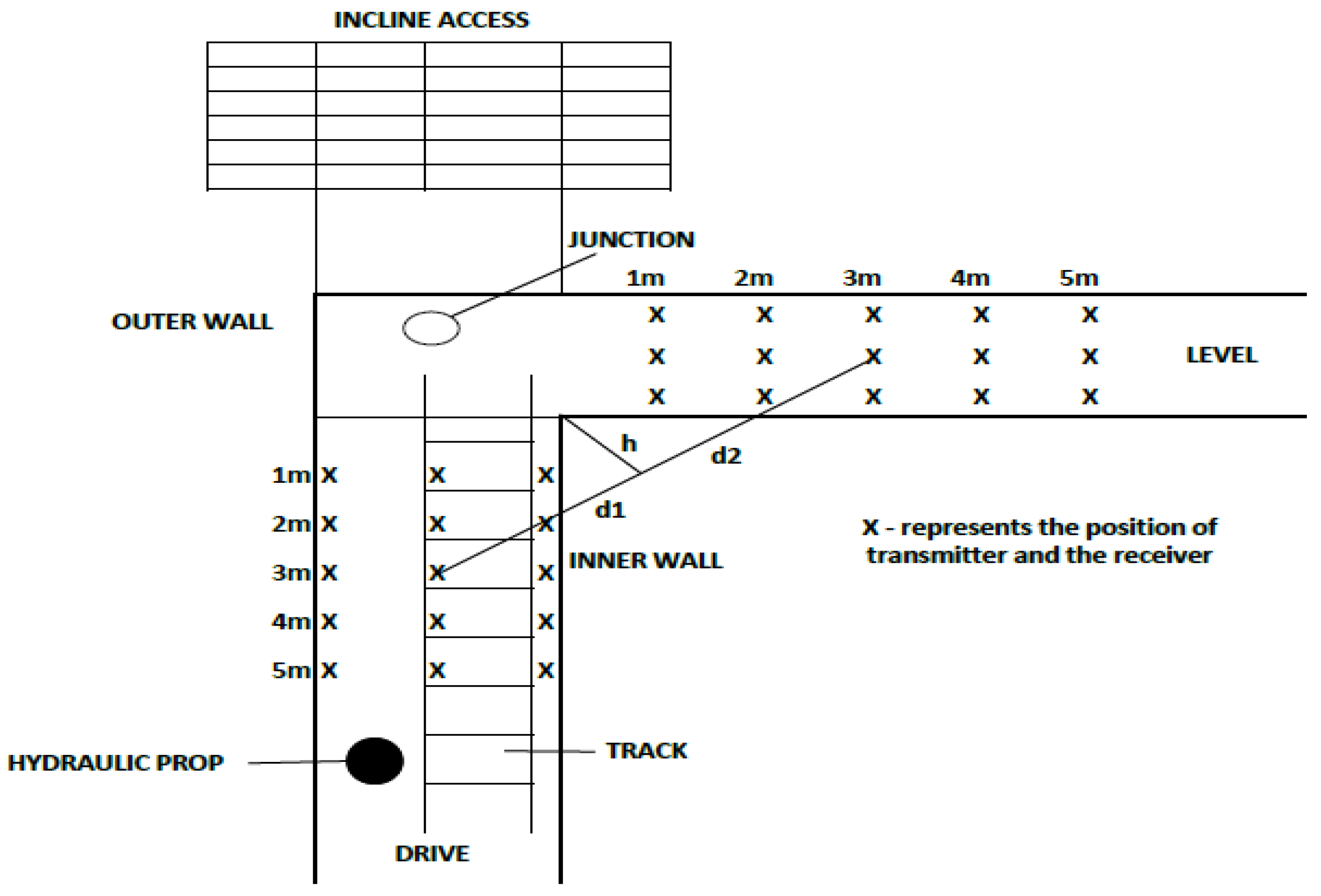
4.8. Measurements near the Drive Junction

The final set of RSSI reading were observed at a junction by positioning the transmitter at 2 m, 4 m and 6 m from the junction at the center of the drive. According to the findings, the signal intensity decreases as the receiver moves near the wall. It is also observed that the signal intensity decreases as the distance between the transmitter and the receiver increases as shown in Figure 15. It is also observed that the position of transmitter does not have much influence on RSSI reading as shown in Figure 15.

4.9. Signal Strength Diffraction Modelling at the Drive Junction

This section describes Fresnel knife edge diffraction and demonstrates how free space is a realistic model for signal transmission over a short distance at a drive junction. The Fresnel diffraction parameter v, which is determined by the distance between the knife edge and the transmitter (d1), the distance between the knife edge and the receiver (d2), the signal wavelength (λ), and the height of the knife edge obstruction (h), defines the diffraction pattern of a Fresnel knife edge as in Equation (3). Figure 13 illustrates the relationship between d1, d2, and h when the transmitter and receiver are both placed in the drive’s centre and 4 m away from the drive junction. The model is constructed with the assumption that the knife edge does not pass through the signal, and it uses free space to simulate both knife edge and receiver propagation. The parameter v is defined as:
v   =   h 2 ( d 1 + d 2 ) ( λ d 1 d 2 )
The diffraction loss G(v) can be calculated using v:
G ( v )   =   6.9   + 20 l o g 10   ( x = ( ( v     0.1 ) 2   +   1   +   v     0.1 )
The loss in free space is predicted by the following equation, where Gt and Gr are the transmitter and receiver antenna gains, λ is the wavelength, and d is the distance between the transmitter and receiver.
P L   ( d B )   =   G t   +   G r   +   20 l o g 10   ( λ 4 π d )
Analyses were made to determine how path loss due to diffraction and free space is estimated for the transmitter and receiver at distances of 4 m from the junction and 1 m from the inner wall. The distance ‘d’ must be established to calculate the free space loss from Equation (5).
The transmitter and receiver are placed orthogonally 3 m away from the knife edge as shown in Figure 13. Each antenna has a 1 dBi gain. This equates to a total distance of 6 m. For a frequency of 433 MHz and the above-mentioned Equation (5), the free space loss is 39 dB. Figure 13 shows that h, d1, and d2 are all roughly 2, which allows to compute the loss due to diffraction using the value of v = 3.4. Consequently, by applying Equation (4), we obtain a 24 dB diffraction loss. The combined loss from diffraction and open space is then 63 dB. The observed RSSI value at the receiver is −56 dBm, despite the transmitter’s power is 10 dBm power. A loss of 66 dB, which is well within the anticipated loss, is equivalent to the difference between the two values.

5. Discussion

As per reg 111, CMR 2017, the maximum size of each pillar is 45 m × 45 m including the width of the gallery (drive). During the development of these pillars, each pillar will be sliced into two halves by driving the gallery. The length of the gallery will be equal to the length of the pillar which will be equal to 45 m. Hence, always there will be a situation that the distance from the position of the transmitter in the line of sight will not be more than 45 m. Because of this, the study of RSSI for non-line of sight is more important. The study conducted in the underground mine model found that for non-line of sight beyond 15 m from the junction signals were not received. Also, it was observed that, at two 90° turns (from drive-1 to level and level to drive-2 in the underground mine model) from the point of the transmitter, signals were not received. This demands the introduction of boosters at every 14 m from the junction for non-line of sight.

5.1. Merits of the Developed System

  • Safety: Underground Coal gas monitoring devices can help ensure the safety of coal miners by detecting the presence of harmful gases. This LoRa system can efficiently transmit the gas concentration levels received from the sensors to the surface of the underground coal mine.
  • Early Detection: The developed device can detect the presence of gases at an early stage, allowing for immediate action to be taken to save the life of miners and mining property.
  • Cost Effective: The LoRa communication system is cost-effective compared to the wired communication system.
  • Mobility: Since it is a wireless communication system, the sensors can be moved and adjusted as required.
  • Long-range communication: LoRa (Long Range) technology provides enabling the system to transmit data over long distances efficiently.
  • Reliability: Since it is a wireless system, it can monitor any nook and corner in an underground mine compared to a wired system.

5.2. Demerits of the Developed System

  • Scalability: LoRa installations will link many endpoint devices engaged in monitoring and communicating activities. When more devices are connected, efficiency should be evaluated.
  • Maintenance: These devices require regular maintenance to ensure their accuracy and reliability.

5.3. Limitations

  • The device was used for a limited depth of 15 m from the surface and to know the nature of RSSI with respect to more depth is not included in this study.
  • The device is tested for Bord and Pillar condition with limited obstacles.

6. Conclusions

The research paper investigated the effectiveness of using LoRa technology for gas monitoring in underground coal mines by placing transmitter and receiver devices at different locations, including the inner wall, outer wall, and centre. Consequently, it can be concluded that the most effective way to monitor gas in underground coal mines using LoRa technology is to place the transmitter and receiver devices at the centre of the drive and the level. The outcome of the test conducted using the developed UGMD (Underground Gas Monitoring Device) with inbuilt LoRa (Long Range) communication in an underground mine model has given encouraging results to extend the research toward underground coal mines for real-time monitoring.
The tests were conducted in an underground mine model, to gain a better understanding of how the UGMD performs in a controlled environment and can identify any potential issues or areas for improvement if any before deploying the device in a real-world setting. Using LoRa communication is a better choice for the UGMD, as it is designed to provide long-range wireless connectivity with low power consumption, making it ideal for use in remote and underground mine. By utilizing LoRa, the UGMD can effectively transmit data over long distances (more than 150 m in line of sight and 15m in non-line of sight without boosters) while conserving battery life, which is important for devices that may need to operate for extended periods without being recharged. To extend the range, boosters (transmitter + receiver) should be placed at every 150 m in line of sight and every 15 m in non-line of sight from the junction for the present condition.

Author Contributions

P.P.K.: Conceptualization, Methodology, Investigation, Formal Analysis, Resources and Original Draft Preparation; P.S.P.: Investigation, Data Curation, Writing-review and editing, Supervision; M.A.: Methodology, Investigation, Data Curation, Formal Analysis, Writing—review and Editing. All authors have read and agreed to the published version of the manuscript.

Funding

This research received no external funding.

Institutional Review Board Statement

The study did not require ethical approval.

Informed Consent Statement

Not applicable.

Data Availability Statement

Due to privacy reasons data will be available on request to the author.

Acknowledgments

The authors are sincerely thankful to Dr. T. Thimmaiah Institute of Technology, Kolar Gold Fields, Karnataka, India for permitting us to carry out the testing of the UGMD system in their Institute’s Underground Mine Model. The authors also like to acknowledge the IIT(ISM), Dhanbad for providing permission for this study.

Conflicts of Interest

The authors declare that they have no known competing financial interest or personal relationships that could have appeared to influence the work reported in this paper.

References

  1. Sanmiquel, L.; Bascompta, M.; Rossell, J.M.; Anticoi, H.F.; Guash, E. Analysis of Occupational Accidents in Underground and Surface Mining in Spain Using Data-Mining Techniques. Int. J. Environ. Res. Public Health 2018, 15, 462. [Google Scholar] [CrossRef]
  2. Ovalioglu, E. Coal Power Plants. Research Gate. 2022. Available online: https://www.researchgate.net/publication/360919314 (accessed on 2 February 2023).
  3. Tripathy, D.P.; Ala, C.K. Identification of safety hazards in Indian underground coal mines. J. Sustain. Min. 2018, 17, 175–183. [Google Scholar] [CrossRef]
  4. Anas, M.; Haider, S.M.; Sharma, P. Gas Monitoring and Testing in Underground Mines using Wireless Technology. Int. J. Eng. Res. Technol. (IJERT) 2017, 6, 412–416. [Google Scholar]
  5. Mishra, P.K.; Swain, A.; Kumar, S.; Mandal, S.K. Wireless Paging System for Underground Mines. Radio Electron. Commun. Syst. 2021, 64, 14–25. [Google Scholar] [CrossRef]
  6. Shahani, N.M.; Sajid, M.J.; Brohi, M.A.; Qureshi, A.R.; Shahani, L.B.; Bachal, S.; Ullah, B. An Empirical Analysis of Fatal Accidents in the Coal Mines of Pakistan. In Proceedings of the International Conference on Energy, Resources, Environment and Sustainable Development, Xuzhou, China, 31 May–3 June 2019. [Google Scholar]
  7. Deng, Y.; Song, L.; Zhou, Z.; Liu, P. An Approach for Understanding and Promoting Coal Mine Safety by Exploring Coal Mine Risk Network. Hindawi 2017, 2017, 7628569. [Google Scholar] [CrossRef]
  8. Jo, B.W.; Khan, R.M.A. An Event Reporting and Early-Warning Safety System Based on the Internet of Things for Underground Coal Mines: A Case Study. Appl. Sci. 2017, 7, 925. [Google Scholar] [CrossRef]
  9. Underwood, P.; Waterson, P. Systemic accident analysis: Examining the gap between research and practice. Accid. Anal. Prev. 2013, 55, 154–164. [Google Scholar] [CrossRef]
  10. Zhang, J.; Zeng, Y.; Reniers, G.; Liu, J. Analysis of the Interaction Mechanism of the Risk Factors of Gas Explosions in Chinese Underground Coal Mines. Int. J. Environ. Res. Public Health 2022, 19, 1002. [Google Scholar] [CrossRef]
  11. Szlazak, N.; Obracaj, D.; Swolkien, J. Enhancing Safety in the Polish High-Methane Coal Mines: An Overview. Min. Metall. Explor. 2020, 37, 567–579. [Google Scholar] [CrossRef]
  12. Li, L.; Yang, Z. Emergency response analysis of fatal gas explosions based on a case study. Chem. Eng. Trans. 2017, 62, 1363–1368. [Google Scholar] [CrossRef]
  13. Mitragotri, S.D.; Karwankar, A.R. Coal Mine Robot for Detection of Hazardous Gas. Int. J. Adv. Res. Electr. Electron. Instrum. Eng. 2016, 5, 4. [Google Scholar]
  14. Cheng, J.W.; Yang, S.Q. Improved Coward Explosive Triangle for Determining Explosibility of Mixture Gas. Process Saf. Environ. Prot. 2011, 89, 89–94. [Google Scholar] [CrossRef]
  15. Bo, C.; Xin, C.; Zhongyi, Z.; Chengwen, Z.; Junliang, C. Web of Things-Based Remote Monitoring System for Coal Mine Safety Using Wireless Sensor Network. Int. J. Distrib. Sens. Netw. 2014, 10, 323127. [Google Scholar] [CrossRef]
  16. Dohare, Y.S.; Maity, T.; Das, P.S.; Paul, P.S. Wireless Communication and Environment Monitoring in Underground Coal Mines–Review. IETE Tech. Rev. 2015, 32, 140–150. [Google Scholar] [CrossRef]
  17. Kumar, A.; Singh, K.; Bhattacharya, D. A Wireless Surveillance and Safety System for Mine Workers based on Zigbee. Int. J. Sci. Eng. Technol. 2013, 2, 979–981. [Google Scholar]
  18. Daoud, M.; Farjow, W.; Fernando, X. A novel diagnostic system for adding reliability to communication networks in underground mines. In Proceedings of the 2011 24th Canadian Conference on Electrical and Computer Engineering (CCECE), Niagara Falls, ON, Canada, 8–11 May 2011; pp. 001342–001346. [Google Scholar]
  19. Lia, M.; Hakem, N.; Ailas, M. Dust effects on Leaky Feeder cable in an underground mine environment. In Proceedings of the IEEE Antennas and Propagation Society International Symposium (APSURSI), Orlando, FL, USA, 7–13 July 2013; pp. 1610–1611. [Google Scholar]
  20. Nutter, R. Underground Coal Mine Communications and Tracking Status SAGO Plus One Year. In Proceedings of the 2007 IEEE Industry Applications Annual Meeting, New Orleans, LA, USA, 23–27 September 2007; pp. 2086–2089. [Google Scholar]
  21. Choudhury, B.; Jha, R.M. A refined ray tracing approach for wireless communications inside underground mines and metro rail tunnels. In Proceedings of the Applied Electromagnetics Conference (AEMC), Kolkata, India, 18–22 December 2011; pp. 1–4. [Google Scholar]
  22. Song, J.-L.; Gao, H.-W.; Song, Y. Research on Transceiver System of WSN Based on V-MIMO Underground Coal Mines. In Proceedings of the WRI International Conference on Communications and Mobile Computing, CMC, Shenzhen, China, 12–14 April 2010; Volume 2, pp. 374–378. [Google Scholar]
  23. Holloway, C.L.; Hill, D.A.; Dalke, R.A.; Hufford, G.A. Radio wave propagation characteristics in lossy circular waveguides such as tunnels, mine shafts, and boreholes. Antennas Propag. IEEE Trans. 2000, 48, 1354–1366. [Google Scholar] [CrossRef]
  24. Zhang, Y.P.; Zheng, G.X.; Sheng, J.H. Radio propagation at 900 MHz in underground coal mines. Antennas Propag. IEEE Trans. 2001, 49, 757–762. [Google Scholar] [CrossRef]
  25. Chaamwe, N.; Liu, W.; Jiang, H. Seismic monitoring in underground mines: A case of mufulira mine in Zambia: Using wireless sensor networks for seismic monitoring. In Proceedings of the International Conference on Electronics and Information Engineering (ICEIE), Kyoto, Japan, 1–3 August 2010; Volume 1, pp. V1-310–V1-314. [Google Scholar]
  26. Landel, S.; Matte, P.N. Coal Mine Monitoring System for Rescue and Protection Using ZigBee. Int. J. Adv. Res. Comput. Eng. Technol. 2015, 4. Available online: https://www.semanticscholar.org/paper/Coal-Mine-Monitoring-System-for-Rescue-and-using-Lande/63577efd5d0fe941e6f7e87dfc5bc648c60cb7f0 (accessed on 24 February 2023).
  27. Chou, J. Hazardous Gas Monitor: A Practical Guide to Selection, Operation, and Applications; McGraw Hill Publication: New York, NY, USA, 1999. [Google Scholar]
  28. Muduli, L.; Mishra, D.P.; Jana, P.K. Application of wireless sensor network for environmental monitoring in underground coal mines: A systematic review. J. Netw. Comput. Appl. 2018, 106, 48–67. [Google Scholar] [CrossRef]
  29. Einicke, G.; Dekker, D.; Hainsworth, D. A Review of Underground Communications Systems.—Exploration and Mining, PO Box 883, Kenmore 4069, Australia. 1997, pp. 1–9. Available online: https://www.academia.edu/18045758/A_Review_of_Underground_Communications_Systems (accessed on 15 February 2023).
  30. Tong, R.; Yang, Y.; Ma, X.; Zhang, Y.; Li, S.; Yang, H. Risk assessment of Miners’ unsafe behaviors: A case study of gas explosion accidents in coal mine. China. Int. J. Environ. Res. Public Health 2019, 16, 1765. [Google Scholar] [CrossRef]
  31. Ranjith, L.; Fanai, L.; Choeden, K.; Kumar, S.; Kumar, P. IoT-Based Power Line Communication in Underground Coal Mines. In Proceedings of the First International Conference on Advanced Scientific Innovation in Science, Engineering and Technology, ICASISET 2020, Chennai, India, 16–17 May 2020. [Google Scholar] [CrossRef]
  32. Doddi, V.K.; Anuradha, N. A Coal Mine Safety System using Wireless Sensor Network. Int. J. Prof. Eng. Stud. 2014, 2, 1–6. [Google Scholar]
  33. Kumar, B.V.; Jayasree, B.; Kiruthika, D. Iot-based underground coal mine safety system. J. Phys. Conf. Ser. 2021, 1717, 012030. [Google Scholar] [CrossRef]
  34. A Technical Overview of LoRa and LoRaWAN, Lora Alliance, San Ramon, US. 2015. Available online: https://www.lora (accessed on 3 March 2023).
  35. Erturk, M.A.; Aydin, M.A.; Buyukakkaslar, M.T.; Evirgen, H. A Survey on LoRaWAN Architecture, Protocol and Technologies. Future Internet 2019, 11, 216. [Google Scholar] [CrossRef]
  36. Zrelli, A.; Ezzedine, T. Design of optical and wireless sensors for underground mining monitoring system. Optik 2018, 170, 376–383. [Google Scholar] [CrossRef]
  37. Semtech SX1301 Datasheet. 2017. Available online: https://datasheet4u.com/datasheet-pdf/Semtech/SX1301/pdf.php?id=1327734 (accessed on 3 February 2020).
  38. LoRa Alliance LoRaWAN 1.1 Specification. 2017. Available online: https://net868.ru/assets/pdf/LoRaWAN-v1.1.pdf (accessed on 3 February 2020).
  39. Isenstein, R.J. US Patent on the Detection of Hazardous Gas Leakage. U.S. Patent No. 5563578, 8 October 1996. [Google Scholar]
  40. Mcfadden, E.F.; Bacharach, Inc. US Patent on Gas Detection Circuitry. U.S. Patent No. US6489787B1, 3 December 2002. [Google Scholar]
  41. Libelium Waspnode LoRa 868Mhz-915Mhz SX1272 Networking Guide. 2015. Available online: http://www.libelium.com/development/waspnode/documentation/waspnode-lora-868mhz-915mhz-sx1272networking-guide (accessed on 3 February 2020).
  42. The Coal Mine Regulations. 2017. Available online: https://www.dgms.gov.in/writereaddata/UploadFile/Coal_Mines_Regulation_1957.pdf (accessed on 27 February 2023).
  43. Branch, P. Measurements and Models of 915 MHz LoRa Radio Propagation in an Underground Gold Mine. Sensors 2022, 22, 8653. [Google Scholar] [CrossRef]
  44. Rappaport, T.S. Wireless Communications: Principles and Practice; Prentice Hall PTR: Hoboken, NJ, USA, 1996; Volume 2. [Google Scholar]
  45. Abrardo, A.; Pozzebon, A. A Multi-Hop LoRa Linear Sensor Network for the Monitoring of Underground Environments: The Case of the Medieval Aqueducts in Siena, Italy. Sensors 2019, 19, 402. [Google Scholar] [CrossRef]
  46. Zhang, J.; Huang, J.; He, Y. A Novel RSSI-Interference Model for Multi-hop Wireless Sensor Networks. In Proceedings of the 2019 IEEE Global Communications Conference (GLOBECOM), Waikoloa, HI, USA, 9–13 December 2019; pp. 1–6. [Google Scholar]
  47. Chen, J.; Ma, X.; Peng, Z. Effect of Device Orientation on RSSI Measurements in Wireless LANs. In Proceedings of the 2020 IEEE 16th International Conference on Wireless and Mobile Computing, Networking and Communications (WiMob), Thessaloniki, Greece, 12–14 October 2020; pp. 1–6. [Google Scholar]
  48. Tang, L.; Lu, Z.; Han, K. The Impact of Channel Asymmetry on RSSI Distance Estimation for Wi-Fi Localization. In Proceedings of the 2018 IEEE International Conference on Communications (ICC), Kansas City, MO, USA, 20–24 May 2018; pp. 1–6. [Google Scholar]
  49. “LoRa Technology Overview” by Semtech. Available online: https://www.semtech.com/uploads/documents/AN1200.22.pdf (accessed on 22 March 2023).
  50. “LoRaWAN 1.0 Specification” by the LoRa Alliance. Available online: https://lora-alliance.org/resource-hub/lorawan-10-specification (accessed on 30 March 2023).
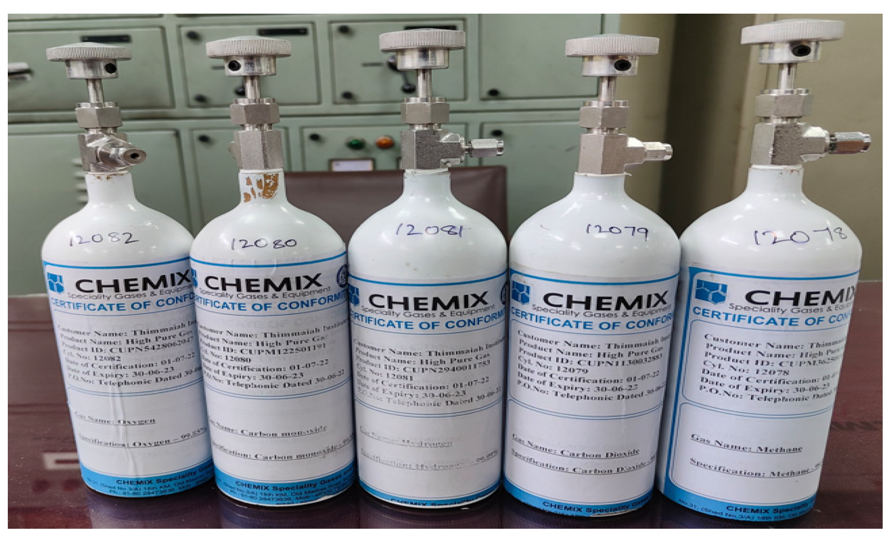
Figure 1. Details of fatalities that occurred in various countries from 2010–2021 [10,11]. (Modified after Zhang et al., 2020 and Szlazak et al., 2020).
Processes 11 01691 g001
Figure 2. CO Explosive Triangle [14] [Modified after Cheng, J.W. et. al., 2011, doi: https://doi.org/10.1016/j.psep.2010.12.001, publisher name: Elsevier, 2011].
Processes 11 01691 g002
Figure 3. LoRaWAN Architecture [39] [Modified after Erturk M A et al., 2019].
Processes 11 01691 g003
Figure 4. Flowchart showing the steps of the work.
Processes 11 01691 g004
Figure 5. Architecture of the monitoring process.
Processes 11 01691 g005
Figure 6. Underground Mine Model at Dr. T. Thimmaiah Institute of Technology.
Processes 11 01691 g006
Figure 7. Gas Canisters.
Processes 11 01691 g007
Figure 8. Transmitter and Receiver Location in Underground Mine Model.
Processes 11 01691 g008
Figure 9. Mean RSSI underground with a trendline.
Processes 11 01691 g009
Figure 10. Histogram of RSSI variation from the mean.
Processes 11 01691 g010
Figure 11. Q-Q Plot of Sample Data versus Standard Normal.
Processes 11 01691 g011
Figure 12. (a). Transmitter positioned at centre while RSSI measured near wall and centre. (b). Transmitter positioned at outer wall while RSSI measured near wall and centre. (c). Transmitter positioned at inner wall while RSSI measured near wall and centre.
Processes 11 01691 g012aProcesses 11 01691 g012b
Figure 13. Knife edge diffraction modelling.
Processes 11 01691 g013
Figure 14. RSSI for Non-line of Sight.
Processes 11 01691 g014
Figure 15. The transmitter is placed at a different distance from Receiver.
Processes 11 01691 g015
Table 1. Permissible limits of various gases as per the Reg. (153)—The Coal Mine Regulations, 2017 [42].
Sl. No.GasesPermissible Limit (%)
1Methane (CH4)0.75 (intake airways)
1.25 (return airways)
2Carbon dioxide (CO2)0.5
3Carbon monoxide (CO)0.005
4Oxygen (O2)19
5Hydrogen Sulphide (H2S)0.0005
Disclaimer/Publisher’s Note: The statements, opinions and data contained in all publications are solely those of the individual author(s) and contributor(s) and not of MDPI and/or the editor(s). MDPI and/or the editor(s) disclaim responsibility for any injury to people or property resulting from any ideas, methods, instructions or products referred to in the content.

