Article

Experimental Study on the Working Efficiency and Exergy Efficiency of the Vehicle-Mounted Thermoelectric Generator for Cold Chain Logistics Transportation Vehicle

1
Intelligent Manufacturing College, Tianjin Sino-German University of Applied Sciences, Tianjin 300350, China
2
Department of Electrical and Computer Engineering, Tandon School of Engineering, New York University, New York, NY 11201, USA
*
Author to whom correspondence should be addressed.
Processes 2023, 11(6), 1782; https://doi.org/10.3390/pr11061782
Submission received: 12 May 2023 / Revised: 6 June 2023 / Accepted: 9 June 2023 / Published: 11 June 2023
(This article belongs to the Special Issue Advances in Waste Heat Recovery Using Thermoelectric Generators)

Abstract

:
This paper investigates a vehicle-mounted thermoelectric generator system working efficiency and exergy efficiency in a cold chain logistics transport vehicle (CLVTEG). The study examines the impact of factors such as load resistance, temperature difference, and copper foam on the performance of CLVTEG. Results demonstrate that adding copper foam significantly improves the output power of CLVTEG, with 40 PPI copper foam showing a 1.8 times increase compared to no copper foam. Additionally, copper foam enhances working and exergy efficiency, with 10 PPI copper foam achieving the best overall efficiency. The study also explores the effect of temperature difference on CLVTEGs efficiency, observing an initial increase followed by a decrease. Overall, this research underscores the importance of considering work and exergy efficiency when evaluating thermoelectric generators. Adding copper foam in the CLVTEG central area enhances heat transfer, resulting in improved efficiency. These findings offer valuable insights for optimizing the design and operation of thermoelectric generators in cold chain logistics transport vehicles.

1. Introduction

With the development of the global economy and the improvement of people’s living standards, cold chain logistics plays an important role as an efficient, safe, and controllable way of goods transportation in modern society. Cold chain logistics involves the transportation of many products, from food, and medicine, to cosmetics, which require high demands for temperature, humidity, and environment to maintain the quality and safety of goods. However, traditional cold chain logistics transport vehicles require a large amount of energy consumption during transportation, and there are problems of energy waste and environmental pollution. To solve this problem, thermoelectric power generation technology, as an emerging energy technology, can be effectively combined with cold chain logistics transport vehicles to provide a more environmentally friendly and sustainable solution for the cold chain logistics industry.
A cold chain transport vehicle is a specialized vehicle used for transporting temperature-sensitive goods, including food, medicine, and biological products. These goods require strict temperature and humidity control during transportation to ensure their quality and safety. Cold chain transport vehicles are typically equipped with professional refrigeration equipment, such as refrigerated compartments and cabinets, to maintain the required temperature throughout the transportation process. In addition, they also have temperature monitoring and a series of electronic control systems to monitor and adjust the temperature inside the compartment in real time, ensuring the goods are transported under proper temperature conditions. However, traditional cold chain transport vehicles have some issues. Firstly, traditional vehicles typically use fuel-driven refrigeration equipment, which consumes a lot of fossil energy, leading to energy waste and environmental pollution [1,2]. Secondly, traditional cold chain transport vehicles need to maintain a low-temperature environment during transportation, which consumes a significant amount of energy to keep the compartment at the required temperature, resulting in energy waste. Furthermore, traditional cold chain transport vehicles also face issues such as rising energy costs and unstable energy supply, which bring significant economic pressure and operational risks to the enterprise. However, by utilizing the waste heat of tail gas through thermoelectric generation technology and converting it into electric energy to supply power to the electronic system on board, the efficiency of secondary utilization of renewable energy will be effectively improved, reducing energy waste and saving energy costs. Therefore, to solve the problems of traditional cold chain transport vehicles, improve their energy utilization efficiency and reduce their environmental impact, thermoelectric generation technology is introduced into cold chain transport vehicles as an emerging energy technology to achieve an effective combination of cold chain transport vehicles and thermoelectric generation technology. Thermoelectric power generation technology is an energy technology that generates electricity by utilizing temperature differences. Based on the thermoelectric effect, the technology produces electric current by connecting two objects with different temperatures using a thermal conductor. Thermoelectric power generation technology can convert heat energy into electric energy, thereby achieving energy conversion and utilization.
Thermoelectric power generation technology has many advantages. Firstly, it can utilize low-quality thermal energy in the environment, such as waste heat and wastewater, to achieve energy reuse and reduce energy waste. Secondly, the technology can work in environments with significant temperature differences, such as areas with high temperatures in summer and low temperatures in winter, thereby improving energy utilization efficiency. In addition, thermoelectric power generation technology does not require fuel combustion, does not produce emissions or noise, and has environmentally friendly and clean characteristics. Thermoelectric power generation technology has been extensively studied and applied in industry, academia, and research. He et al. [3] reviewed recent developments and applications of thermoelectric generators (TEGs) and coolers, covering advances in materials, device design, and performance optimization. Pourkiaei et al. [4] provided a comprehensive review of thermoelectric cooling and power generation devices, discussing the current state of the art in modeling, materials, and applications. Champier [5] reviewed the applications of thermoelectric generators, discussing their use in power generation, waste heat recovery, and cooling systems. Amatya and Ram [6] designed and tested a solar thermoelectric generator for micropower applications. The experiment showed that the generator could produce electricity from solar radiation, and the output power was sufficient to power small electronic devices. Yan et al. [7] reviewed micro thermoelectric generators, focusing on their design, fabrication, and performance. Niu et al. [8] conducted an experimental study on a low-temperature waste heat thermoelectric generator. The experiment demonstrated the feasibility of generating electricity from low-temperature waste heat, and the performance of the generator was analyzed and optimized. Kim et al. [9] fabricated a wearable thermoelectric generator on a glass fabric substrate. The experiment demonstrated the potential of thermoelectric generators for wearable energy harvesting applications. Jouhara et al. [10] reviewed the latest thermoelectric generator technologies and their applications, including power generation from waste heat, solar energy, and radioisotopes. Karri et al. [11] investigated exhaust energy conversion using a thermoelectric generator in two case studies. The experiments demonstrated the feasibility of using thermoelectric generators to convert exhaust energy into electricity in a variety of applications. Luo et al. [12] contribute to the field of automotive thermoelectric power generation by presenting a hybrid model that combines CFD and thermal resistance techniques. The model offers a more accurate and detailed analysis of TEG performance, facilitating the development of efficient and effective TEG systems for automobiles. Li et al. [13] designed a concentration solar thermoelectric generator that utilized a parabolic trough to focus solar radiation onto a thermoelectric element. The experiment demonstrated the potential of this technology for solar power generation, and the performance of the generator was analyzed and optimized. He et al. [14] investigated the influence of different cooling methods on the thermoelectric performance of an engine exhaust gas waste heat recovery system. The results showed that air cooling had the best cooling effect and could improve thermoelectric performance by 5.2% compared to water cooling. Lu et al. [15] investigated the effects of heat enhancement for exhaust heat exchangers on the performance of a thermoelectric generator. The study found that using a heat enhancement method could increase the temperature difference and heat transfer coefficient, resulting in higher power output for the thermoelectric generator. Zhao et al. [16] investigated the performance of an intermediate fluid thermoelectric generator for automobile exhaust waste heat recovery. The results showed that the thermoelectric generator could achieve a maximum power output of 240 W, with an overall conversion efficiency of 6.1%. He et al. [17] proposed an optimization design method for a thermoelectric generator based on exhaust gas parameters to recover engine waste heat. The results showed that the optimized design could improve the power output by 15.3% compared to the initial design. Zhao et al. [18] analyzed the thermoelectric generation characteristics of flue gas waste heat from a natural gas boiler. The results showed that the thermoelectric generator could achieve a maximum conversion efficiency of 5.4%, and increasing the temperature difference could significantly improve the power output. Li et al. [19] investigated the influence of porous foam metal filled in the core flow area on the performance of thermoelectric generators. The results showed that the porous foam metal could improve the heat transfer performance and increase the output power of the thermoelectric generator. Ge et al. [20] proposed a structural optimization method for thermoelectric modules in a concentration photovoltaic-thermoelectric hybrid system. The optimization results showed that the power output of the hybrid system could be increased by 25.7% compared to the initial design. He et al. [21] proposed a structural size optimization method for an exhaust exchanger based on the fluid heat transfer and flow resistance characteristics applied to an automotive thermoelectric generator. The optimization results showed that the optimized design could improve the overall performance of the thermoelectric generator. Zhao et al. [22] investigate the experimental study of a heat pipe thermoelectric generator. The experimental tests were conducted to investigate the power generation performance of the heat pipe thermoelectric generator under different operating conditions, and optimization methods were proposed to improve the power generation performance. Zhao et al. [23] analyzed an automobile exhaust thermoelectric generator system that uses a media fluid as the heat transfer medium. The performance of the system was investigated through numerical simulation and experimental studies. Zhao et al. [24] presented an energy and exergy analysis of a thermoelectric generator system with humidified flue gas. The aim was to investigate the effects of humidity on the system performance, and optimization methods were proposed to improve the energy and exergy efficiencies. The effects of heat transfer characteristics between fluid channels and thermoelectric modules on optimal thermoelectric performance were investigated by He et al. [25]. The results showed that optimizing heat transfer can significantly improve the thermoelectric performance of the system. Li et al. [26] presented an experimental study on heat transfer enhancement of a gas tube partially filled with metal foam. The results showed that the metal foam could significantly enhance the heat transfer performance, which is beneficial for the improvement of the overall system performance. Zhao et al.’s [27] analysis of a thermoelectric generator applied to wet flue gas waste heat recovery was investigated in this study. The results showed that the thermoelectric generator could effectively recover the waste heat of wet flue gas, and optimization methods were proposed to improve the system performance. An experimental study of a thermoelectric generator with different numbers of modules for waste heat recovery was conducted by Ge et al. [28]. The results showed that the number of modules has a significant effect on the system performance, and an optimal configuration of modules was proposed to improve the system performance. Zhao et al. [29] presented a characteristics analysis of an exhaust thermoelectric generator system with heat transfer fluid circulation. The results showed that the heat transfer fluid circulation could effectively improve the system performance, and optimization methods were proposed to improve the overall system performance. Zhao et al. [30] investigated thermoelectric power generation using LNG cold energy and flue gas heat. The experimental results showed that the proposed system could effectively recover the waste heat of flue gas and the cold energy of LNG, and optimization methods were proposed to improve the system’s performance. Li et al. [31] presented an experimental study on the effect of core flow heat transfer enhancement on the performance of TEG. The results showed that the core flow heat transfer enhancement could significantly improve the system performance, and optimization methods were proposed to improve the overall system performance. A numerical investigation of an exhaust thermoelectric generator with a perforated plate was conducted by Zhao et al. [32]. The results showed that the perforated plate could effectively improve the heat transfer performance, and optimization methods were proposed to improve the overall system performance. Therefore, thermoelectric power generation technology is considered a promising renewable energy technology that can be applied in various fields, including cold chain logistics transport vehicles.
The combination of cold chain logistics transport vehicles and thermoelectric power generation technology can achieve green, environmentally friendly, and efficient cold chain transportation. Applying thermoelectric power generation technology to the tailpipe exhaust channel of cold chain logistics transport vehicles makes it possible to solve the energy waste and environmental pollution problems associated with traditional cold chain transportation vehicles, improve energy utilization efficiency during transportation, reduce operating costs, and minimize environmental impact. At the same time, the combination of cold chain logistics transport vehicles and thermoelectric power generation technology can also improve the environmental friendliness of cold chain transportation. Traditional cold chain transportation vehicles require a large amount of energy to maintain low temperatures during transportation, resulting in high energy consumption. However, the application of thermoelectric power generation technology can reduce the dependence on external energy sources, thereby reducing the consumption of fossil fuels, lowering greenhouse gas emissions, and minimizing environmental pollution. This helps to promote the development of the cold chain logistics transportation industry towards a low-carbon and environmentally friendly direction, which is in line with the current society’s requirements for sustainable development and environmental protection. In addition, the combination of cold chain logistics transport vehicles and thermoelectric power generation technology can also improve energy self-sufficiency during transportation. By utilizing the electricity generated by thermoelectric power generation technology, it is possible to provide an independent energy supply for cold chain logistics transport vehicles, reducing the dependence on external power grids. This can provide a more reliable energy guarantee for long-distance transportation or in situations where the energy supply is unstable, ensuring the continuous operation of cold chain transportation.
In summary, the integration of cold chain logistics transport vehicles and thermoelectric power generation technology presents a compelling solution with immense potential. The methodology proposed in this paper leverages thermoelectric power generation technology to optimize cold chain transportation, offering a range of benefits that align with the requirements of sustainable development and environmental protection. The central aspect of this method involves the utilization of thermoelectric modules within cold chain logistics transport vehicles. These modules are strategically placed to capture waste heat generated during the transportation process. Through the thermoelectric effect, this waste heat is converted into usable electric power, which can be employed to power various systems within the vehicle. By harnessing waste heat and transforming it into electricity, the method enhances the energy utilization efficiency of cold chain logistics transport vehicles. The generated power can be directed towards operating critical components, such as refrigeration units, telemetry devices, and data logging equipment. This ensures a consistent power supply for maintaining optimal temperature conditions and monitoring the quality of perishable goods throughout the transportation journey. Implementing thermoelectric power generation technology in cold chain logistics transport vehicles not only improves energy efficiency but also reduces operating costs. By decreasing reliance on traditional power sources, such as fossil fuels, the method mitigates fuel consumption and associated expenses. This contributes to significant cost savings for logistics companies while simultaneously minimizing their carbon footprint. In conclusion, the integration of cold chain logistics transport vehicles with thermoelectric power generation technology offers a practical and valuable solution. The methodology presented here capitalizes on thermoelectric modules to capture waste heat and convert it into usable electric power, optimizing energy efficiency and reducing operating costs. Moreover, this method contributes to environmental sustainability by reducing greenhouse gas emissions. By implementing this innovative approach, the cold chain logistics industry can embrace a greener and more efficient future.

2. Working Efficiency and Exergy Efficiency of Cold Chain Logistics Transport Vehicles Thermoelectric Generator (CLVTEG)

2.1. Working Efficiency

Usually, the performance of a thermoelectric generator is affected by many factors. The current evaluation index is mainly working efficiency, but in the utilization of low-grade energy, it is not comprehensive to evaluate only working efficiency. This paper evaluates the working performance of the vehicle-mounted thermoelectric generator of the cold chain logistics transport vehicle (CLVTEG) from two aspects of work efficiency and exergy efficiency. It explores the changing law of working efficiency and exergy efficiency under different working conditions through experiments.
When the temperatures of the hot and cold sides of CLVTEG are T h and T c , respectively, the output power P is determined by the load resistance R, and the expression is as follows:
P = I 2 R
where P —output power, R—load resistance, I—current in the loop.
When the CLVTEG is working, the Peltier heat extracted by the thermoelectric module from the cold side per unit time is α P N T h I . Due to the temperature difference between the cold and hot sides, the hot side of the thermoelectric module will transfer heat to the cold side. When the thermal conductivity of the thermoelectric module is k , its conduction heat is k T h T c . In addition, when the current I flows through the thermoelectric module with resistance R 0 , half of the generated Joule heat is transmitted to the hot side and the cold side of the module. Therefore, the heat absorbed by the hot side of CLVTEG from the heat source should be the sum of the three parts of Peltier heat, conduction heat, and Joule heat, and the expression is as follows:
Q h = α P N T h I + k T h T c 1 2 I 2 R 0
where Q h —heat absorbed by the hot side of CLVTEG from the heat source; α P N —Seebeck coefficient of the thermoelectric module; T h , T c —temperature of the hot side and the cold side, respectively; k —thermal conductivity of the thermoelectric module; I —current in the loop; R 0 —Internal resistance of thermoelectric module.
The working efficiency expression of CLVTEG is as follows:
η = P Q h = I 2 R α P N T h I + k T h T c 1 2 I 2 R 0

2.2. Exergy Efficiency

The temperature at the hot temperature side of CLVTEG is T h , the temperature at the cold temperature side is T c , and the heat taken from the hot side is Q h , then the payout exergy expression is as follows:
E x Q = 1 T c T h Q h
The income exergy of CLVTEG is its output power under different load resistances, and the expression is as follows:
E x = P = I 2 R
The expression of the exergy efficiency of CLVTEG is as follows:
η x = E x E x Q = I 2 R 1 T c T h Q h = η 1 T c T h
where η x —exergy efficiency; E x —income exergy; E x Q —payout exergy.

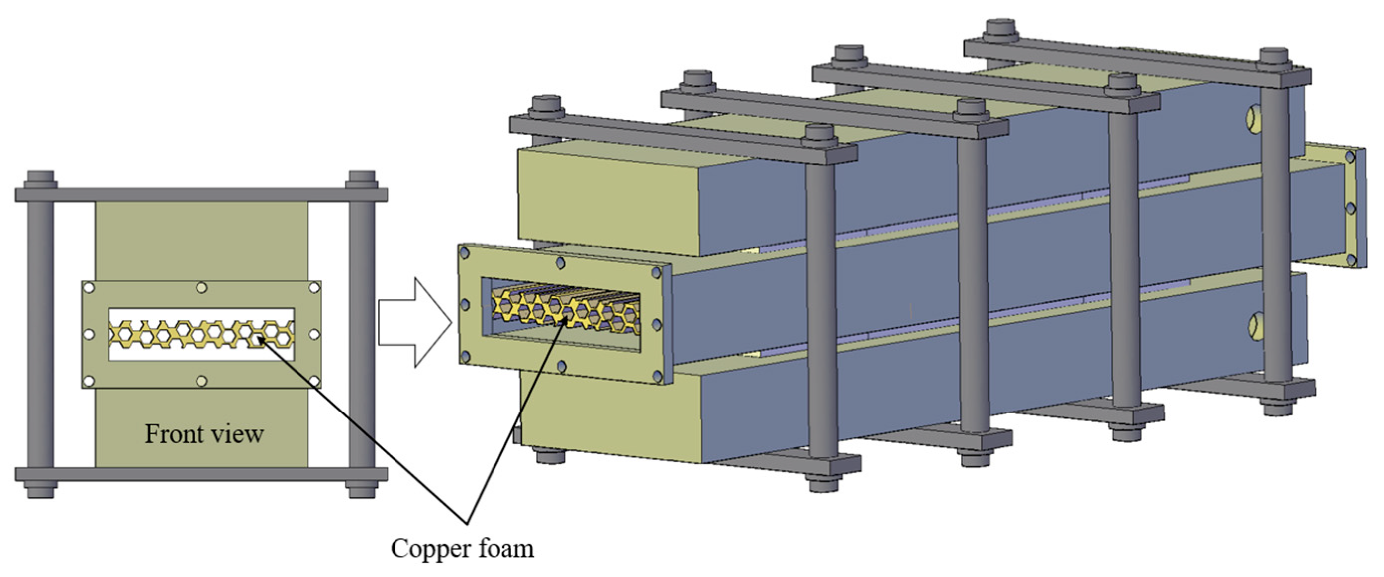
3. Introduction of CLVTEG Experimental System

3.1. CLVTEG Experimental System

In this paper, the exhaust channel of the logistics cold chain transport vehicle is simulated experimentally, and a thermoelectric power generation device is installed on the channel. The thermoelectric generator consists of three parts, the middle is a high-temperature exhaust gas channel, and the two sides are low-temperature cooling water channels. Thermoelectric modules are installed between the high- and low-temperature channels. The thermoelectric module used in this paper is TEHP1-12656-0.3. The basic parameters can be seen in Table 1, and the performance curve is shown in Figure 1. The thermoelectric module is made of Bi-Te-based thermoelectric materials. The whole device is fixed by four sets of fixtures. Its structure is shown in Figure 2, and the structural dimensions are shown in Table 2. The high-temperature air used in the experiment enters the high-temperature exhaust channel of the thermoelectric generator and exchanges heat with the channel wall, and the heat on the other side of the thermoelectric module is taken away by the cooling water in the low-temperature cooling water channel. Therefore, a temperature difference is generated at both sides of the thermoelectric module, and through the Seebeck effect, the thermoelectric module can convert heat energy into electrical energy.

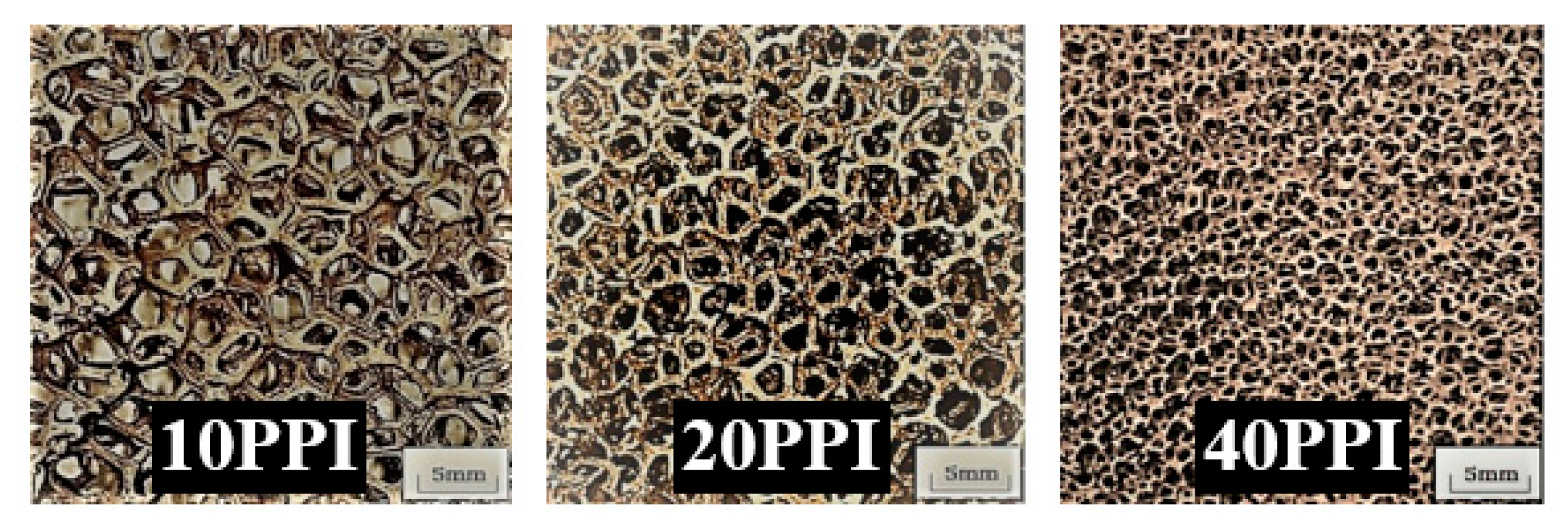
3.2. Enhanced CLVTEG Performance

To improve the performance of CLVTEG, we also made some modifications to it, as seen in Figure 3. The heat transfer effect inside the channel is enhanced by adding foamed copper to the central area of the high-temperature gas channel of CLVTEG, the copper foams are shown in Figure 4. On the one hand, the high thermal conductivity and temperature uniformity of copper foam is used to improve the heat exchange capacity of the fluid in the channel; on the other hand, since the copper foam is only added in the central area, the magnitude of the increase in pressure drop caused by the addition of the copper foam can be effectively reduced. In this paper, there are four methods of filling copper foam in the experiment, and the basic parameters of each copper foam filling method are listed in Table 3. By verifying the reliability and measurement error of the experimental results, the error is less than 5.2%. Therefore, it can be considered that the experimental results are reliable.
This study focuses on investigating the system working efficiency and exergy efficiency of vehicle-mounted thermoelectric generators in cold chain logistics transportation vehicles. The primary objective is to enhance the overall performance of CLVTEG and optimize its energy utilization, operational costs, and environmental impact. By achieving these goals, we contribute to sustainable development and environmental preservation. To conduct this research, we have established an experimental device that simulates the exhaust gas channel of a cold chain logistics transportation vehicle. The experimental setup allows us to simulate the exhaust conditions of cold chain logistics transportation vehicles and accurately evaluate the performance of CLVTEG. Several key parameters, such as load characteristics, temperature difference, and the addition of different types of copper foam, have been combined in the experiments. A series of experiments have been conducted to measure the output power of the thermoelectric generator and evaluate its working efficiency and exergy efficiency. The experiments were carried out under controlled conditions to ensure consistent and reliable results. Our approach has several notable advantages and key features. By integrating thermoelectric power generation technology into cold chain logistics transportation vehicles, we achieve green, environmentally friendly, and efficient cold chain transportation. This method improves energy utilization efficiency, reduces operational costs, and minimizes the environmental impact of exhaust waste heat. Additionally, our research emphasizes the importance of considering both working efficiency and exergy efficiency when evaluating the performance of thermoelectric generators.

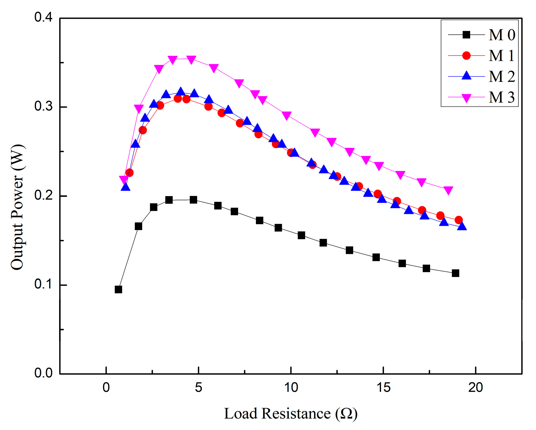
4. Experimental Results and Analysis

The experimental conditions in this paper are that the inlet gas flow rate is 30 m3/h, and the inlet gas temperature is 100 °C. Under the experimental conditions in this paper, the addition of different types of copper foam in the central area of the internal channel of CLVTEG has a significant effect on its performance. The results showed that CLVTEG, with the addition of copper foam in M3, has the best performance in terms of output power and heat transfer coefficient in the channel because the addition of copper foam improves the heat transfer efficiency of the gas in the channel, which makes the hot side temperature and output power of CLVTEG improved. Depending on the addition of different copper foam pore densities, the maximum output power can be increased by 1.8 times.
Figure 5 shows how the output power of CLVTEG changes with the change in external resistance. When the external resistance is zero, the circuit is in a short circuit, and no current can be formed, so the output power is zero. As the external resistance increases, the current in the circuit gradually increases, generating more electrical power, and the output power gradually increases. When the external resistance is equal to the CLVTEG internal resistance, the circuit is in the maximum power transfer state when the output power reaches its maximum value. Then, as the external resistance continues to increase, the current in the circuit gradually decreases, and the output power begins to decrease. This is because, according to the electrical theory, the power transfer in the circuit is most efficient when the internal resistance of the circuit is equal to the external resistance. In this case, the entire circuit has the minimum resistance and the maximum current, which results in the maximum output power of the CLVTEG. In other words, when the external resistance is equal to the internal resistance, the circuit reaches the maximum power matching state. At this point, the maximum power that can be output by the CLVTEG is transferred to the external circuit to the maximum extent, so the output power reaches its maximum. As the external resistance continues to increase, the current in the circuit will decrease, and the output power of CLVTEG is proportional to the current in the circuit, so the output power also decreases. The figure also shows that the output power of CLVTEG with the addition of copper foam (M1-3) is higher than that of the case without the addition (M0). In addition, the CLVTEG with 40 PPI copper foam (M3) has the highest output power, while the CLVTEG with 10 PPI copper foam (M1) has the lowest output power. This is due to the fact that the addition of high pore density copper foam in the central area inside the CLVTEG increases the turbulence intensity inside the gas channel with little increase in pressure drop, which increases the heat transfer coefficient inside the channel, increasing the temperature of the outer wall surface of the channel, resulting in an increase in the temperature difference between the hot and cold sides of the thermoelectric module on the wall surface and the open circuit voltage, which in turn increases the output power of the CLVTEG, as shown in Figure 6 and Figure 7. The addition of higher PPI (i.e., smaller copper foam hole size) copper foam can provide more heat conduction paths, allowing more heat to be transferred to the channel walls, and the larger copper foam solid frame can better act as a disturbance element for the gas. Therefore, compared to a CLVTEG with 10 PPI copper foam, a CLVTEG with 40 PPI copper foam provides more heat conduction paths and more flow disturbance strength, which allows more heat to be utilized and, therefore, higher output power for the CLVTEG. From Figure 6 and Figure 7, it can also be observed that the temperature difference and heat transfer coefficient of the CLVTEG exhibit a nearly linear trend from M1 to M2. However, they experienced a sudden increase from M2 to M3. Comparative analysis of the physical properties of 10 PPI, 20 PPI, and 40 PPI copper foam reveals that 10 PPI and 20 PPI copper foam exhibit similar characteristics in terms of pore density and foam structure. The structures appear very similar, based on Figure 4. Therefore, the roles played by 10 PPI and 20 PPI copper foam in CLVTEG will also be very similar. Consequently, the temperature difference and heat transfer coefficient between these two configurations are expected to demonstrate similar experimental results. However, the sudden increase in temperature difference and heat transfer coefficient observed from M2 to M3 can be attributed to the unique physical structure of 40 PPI copper foam. Figure 4 shows that 40 PPI copper foam exhibits higher pore density and a more complex foam structure compared to 10 PPI and 20 PPI copper foam. This leads to significantly higher temperature difference and heat transfer coefficient in CLVTEG filled with 40 PPI copper foam compared to those filled with 10 PPI and 20 PPI copper foam. Therefore, these differences in physical structure explain the sudden and significant increase in temperature difference and heat transfer coefficient between 40 PPI copper foam and 10 PPI/20 PPI copper foam.
Figure 8 and Figure 9 show the working efficiency and exergy efficiency of CLVTEG in different working conditions. As can be seen from the figure, with the change in load resistance R, CLVTEGs working efficiency and exergy efficiency both had a maximum peak. When the load resistance R was equal to CLVTEG internal resistance R0, both working efficiency and exergy efficiency reached a maximum value. As the load resistance R changed near the peak, exergy efficiency decreased faster than working efficiency, which means exergy efficiency was more sensitive to the change in CLVTEG load resistance. When the load resistance of CLVTEG changes, the change in working efficiency and exergy efficiency can be explained from the perspective of energy conversion.
Exergy efficiency refers to the proportion of temperature difference converted into electricity, while exergy efficiency refers to the ratio of exergy income to exergy payout. When the load resistance is small, the output power of CLVTEG is small, and due to the existence of internal resistance, part of the electric energy is also consumed by the internal resistance, resulting in a lower proportion of the temperature difference into electric energy and low working efficiency. With the increase in load resistance, the output power gradually increases, and due to resistance matching, the internal resistance consumes the least electric energy. Currently, the working efficiency of CLVTEG gradually increases until it reaches the maximum value. As the load resistance continues to increase, the output power begins to decrease, and the working efficiency of CLVTEG will also decrease. Exergy efficiency is affected by output power and internal resistance. When the load resistance is small, the output power is small, and the power loss of the internal resistance is also small, so the exergy efficiency is low. As the load resistance increased, the output power gradually increased. Still, the power loss of internal resistance also began to rise, as a result of which exergy efficiency began to grow slowly. When the load resistance is equal to the internal resistance, the power loss of the internal resistance reaches the minimum value, while the exergy efficiency reaches the maximum value. As the load resistance continued to increase, the power loss of internal resistance continued to increase, and the output power began to decline, while exergy efficiency also began to decline. As a result, work efficiency and exergy efficiency peaked when the load resistance changed, while exergy efficiency was more sensitive to the change in load resistance near the peak value, this is because when the load resistance is equal to the internal resistance, the circuit is in the maximum power transfer state, when the electrical energy conversion efficiency is the highest, and as the load resistance increases, the output power gradually decreases, resulting in the energy conversion efficiency also decreases, which leads to a faster rate of reduction in exergy efficiency.
It can also be seen from the figure that the working efficiency and exergy efficiency of CLVTEG with the addition of copper foam are higher than those of CLVTEG without the addition of copper foam. The working efficiency and exergy efficiency of CLVTEG with the addition of 10 PPI copper foam are higher than those of CLVTEG with the addition of 20 PPI and 40 PPI copper foam. The changing trend of exergy efficiency is more obvious than that of working efficiency. This is due to the high thermal conductivity and high specific surface area of the copper foam frame, which makes the temperature distribution of the gas in the channel more uniform and increases the heat transfer area and heat transfer, increasing the effective heat transfer coefficient between the gas in the channel and the wall and making the working efficiency and exergy efficiency improve. However, the addition of copper foam also increases the gas resistance in the channel, which in turn makes the exergy efficiency decrease because the exergy efficiency is related to the gas flow and gas temperature distribution in the CLVTEG channel. When the pore density of the added copper foam is small, although it can improve the heat transfer effect in the channel, the increased gas resistance is relatively small. It will not have a significant impact on the exergy efficiency, making the working efficiency and exergy efficiency of CLVTEG higher. While adding too high a pore density of copper foam (40 PPI), the increased gas resistance will seriously affect the flow and temperature distribution of gas in the channel, which makes the exergy efficiency decrease obviously, making both the working efficiency and exergy efficiency of CLVTEG lower and the exergy efficiency decrease is more obvious. Therefore, when 10 PPI copper foam is added, it can improve the working efficiency of CLVTEG without significantly affecting the exergy efficiency due to the moderate pore density, making the total efficiency of CLVTEG reach the maximum value.
From Figure 10 and Figure 11, it can be seen that as the temperature difference, ΔT, between the hot and cold sides in the CLVTEG gradually increases, the working efficiency and exergy efficiency of the CLVTEG both increase and then decrease, but the exergy efficiency has a more obvious change near the peak. This is because the addition of copper foam can increase the degree of heat conduction and disturbance in the channel, which makes the temperature distribution in the channel more uniform, reducing the temperature difference inside the channel. At the same time, the copper foam itself has high thermal conductivity, which can effectively help transfer heat. This allows the thermoelectric module attached to the outside of the channel to utilize the heat more fully inside the channel, resulting in a greater temperature difference, higher working efficiency, and exergy efficiency. This phenomenon reaches its best when 10 PPI of copper foam is added. As the temperature difference continues to increase, that is, as the PPI increases, the working efficiency and exergy efficiency of CLVTEG then decrease, and the exergy efficiency tends to decrease more significantly. This is because after the addition of copper foam in the central area inside the CLVTEG, as the pore density of copper foam increases, the more intense the intensity of the disturbance flow in the channel, the better the heat transfer effect is, and the easier the thermoelectric effect is formed. Therefore, the hot and cold sides of CLVTEG, with the addition of copper foam with a larger pore density of 40 PPI, are more likely to form a temperature difference and generate a thermoelectric effect. However, too large a pore density will make the resistance in the channel increase, which will make the working efficiency and exergy efficiency decrease. In contrast, CLVTEG, with a smaller pore density of 10 PPI copper foam, has larger pores and is filled in the central area, so the increase in resistance in the channel is not significant. The overall working efficiency and exergy efficiency of CLVTEG are higher, although the reduced perturbation strength makes the temperature difference smaller and makes the thermoelectric effect weaker. Therefore, the performance of CLVTEG with the addition of 40 PPI copper foam with higher pore density is poor.

5. Conclusions

In conclusion, this paper evaluated the performance of the vehicle-mounted thermoelectric generator of the cold chain logistics transport vehicle (CLVTEG) by considering both working efficiency and exergy efficiency. Experimental investigations were conducted to explore the changing laws of working efficiency and exergy efficiency under different working conditions. The results revealed the following key findings:
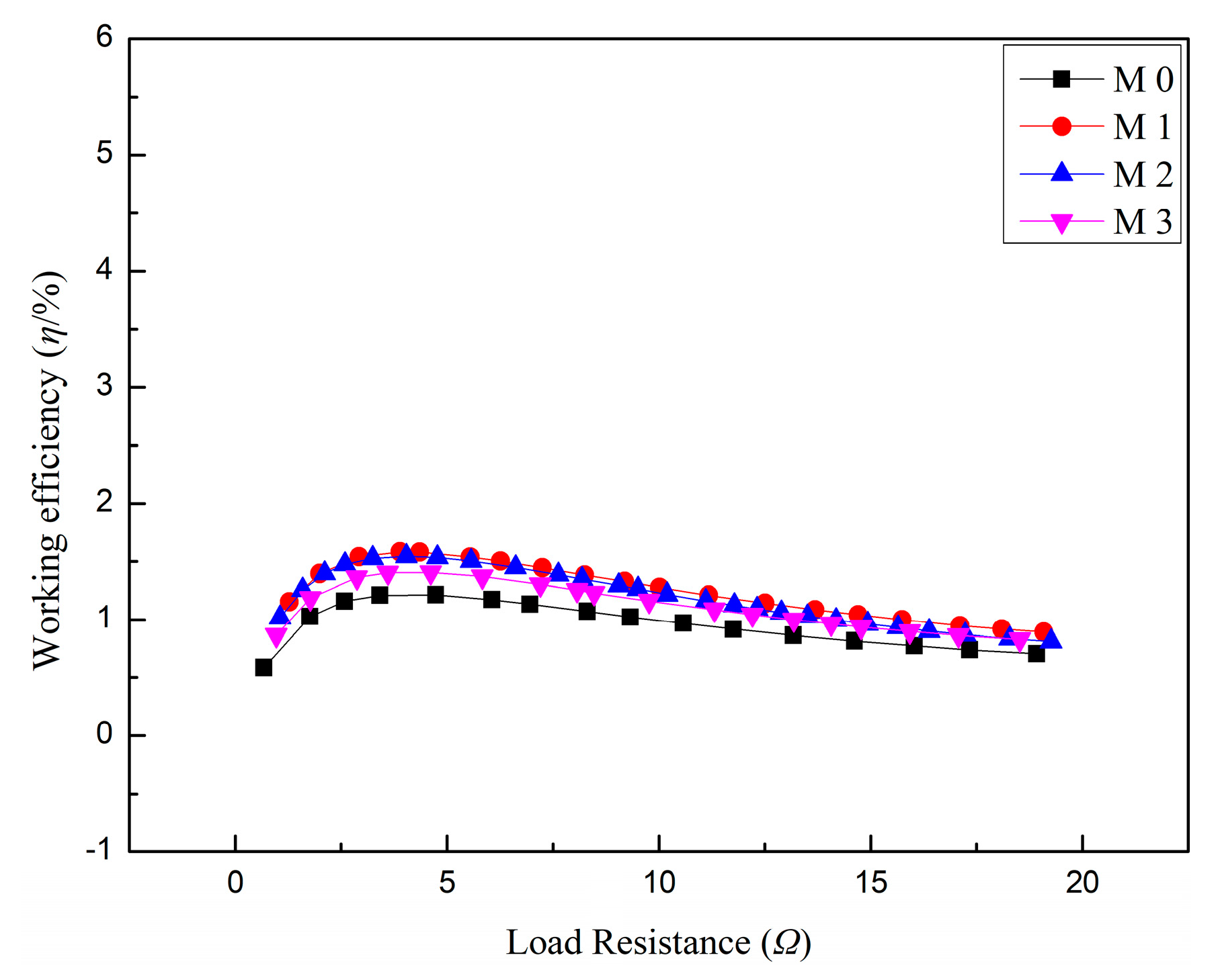
  • The working efficiency of CLVTEG was evaluated based on the output power and heat absorbed by the hot side from the heat source. It was observed that the addition of copper foam in the central area of the high-temperature gas channel significantly improved the performance of CLVTEG. The CLVTEG with 40 PPI copper foam exhibited the highest output power, while the CLVTEG with 10 PPI copper foam had the lowest output power. The increase in output power was attributed to enhanced heat transfer efficiency and temperature difference between the hot and cold sides of the thermoelectric module. Moreover, the addition of higher PPI copper foam provided more heat conduction paths and improved flow disturbance strength, resulting in higher output power.
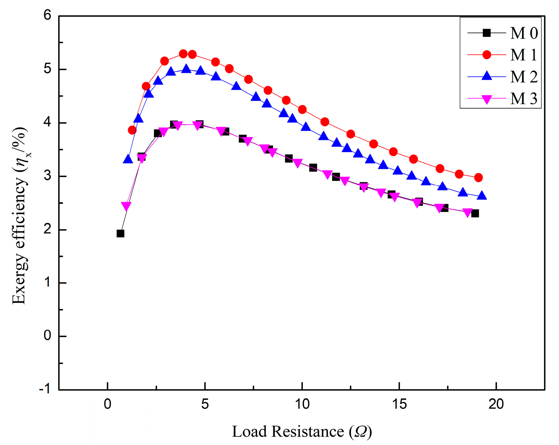
  • The exergy efficiency of CLVTEG was determined by the proportion of temperature difference converted into electricity. It was found that both working efficiency and exergy efficiency exhibited a maximum peak with the change in load resistance. When the load resistance was equal to the internal resistance of CLVTEG, both efficiencies reached their maximum values. Exergy efficiency was more sensitive to changes in load resistance near the peak value. The addition of copper foam increased the working efficiency and exergy efficiency of CLVTEG. The CLVTEG with 10 PPI copper foam demonstrated higher efficiencies compared to those with 20 PPI and 40 PPI copper foam. The change in exergy efficiency was more pronounced than that of working efficiency.
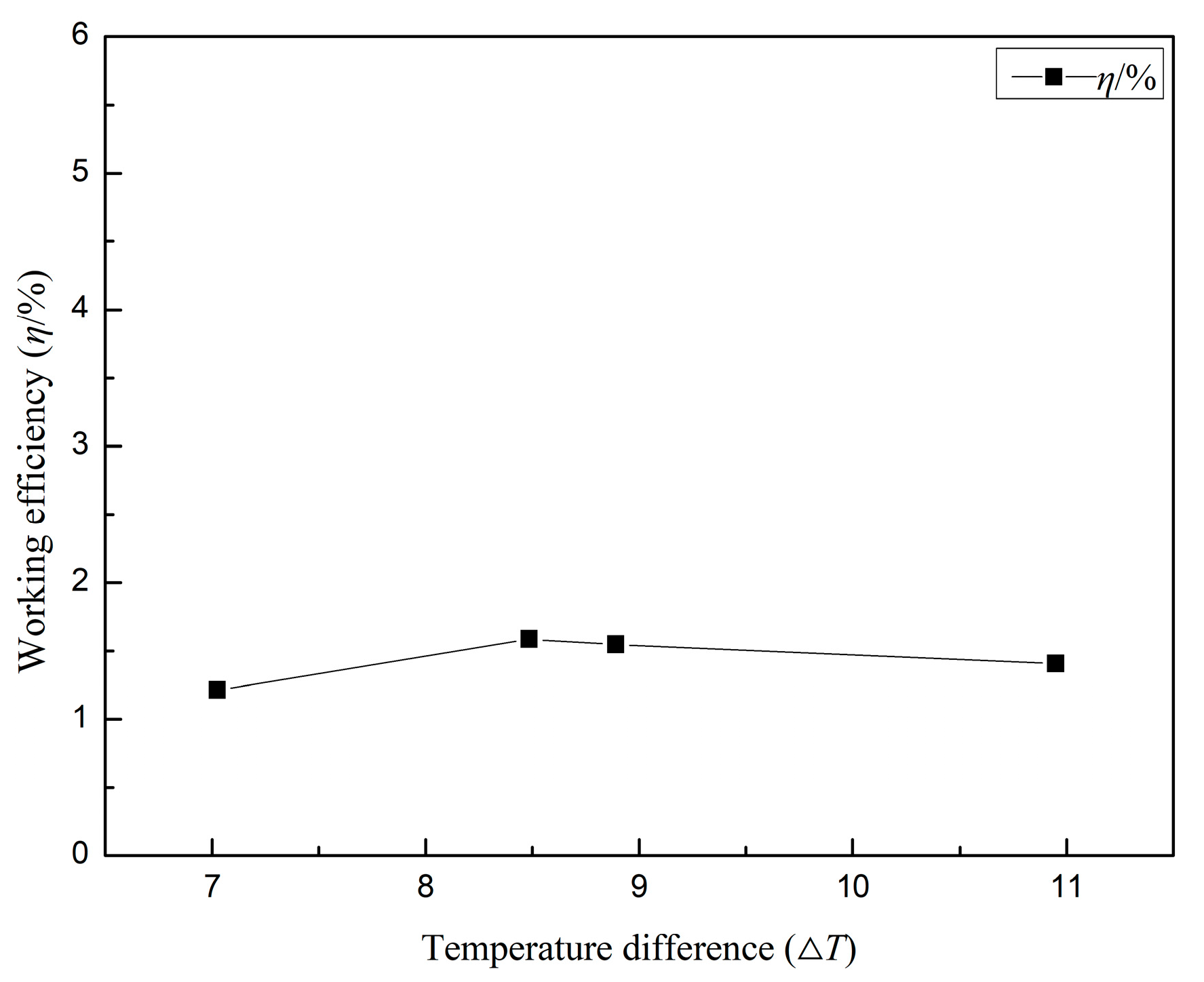
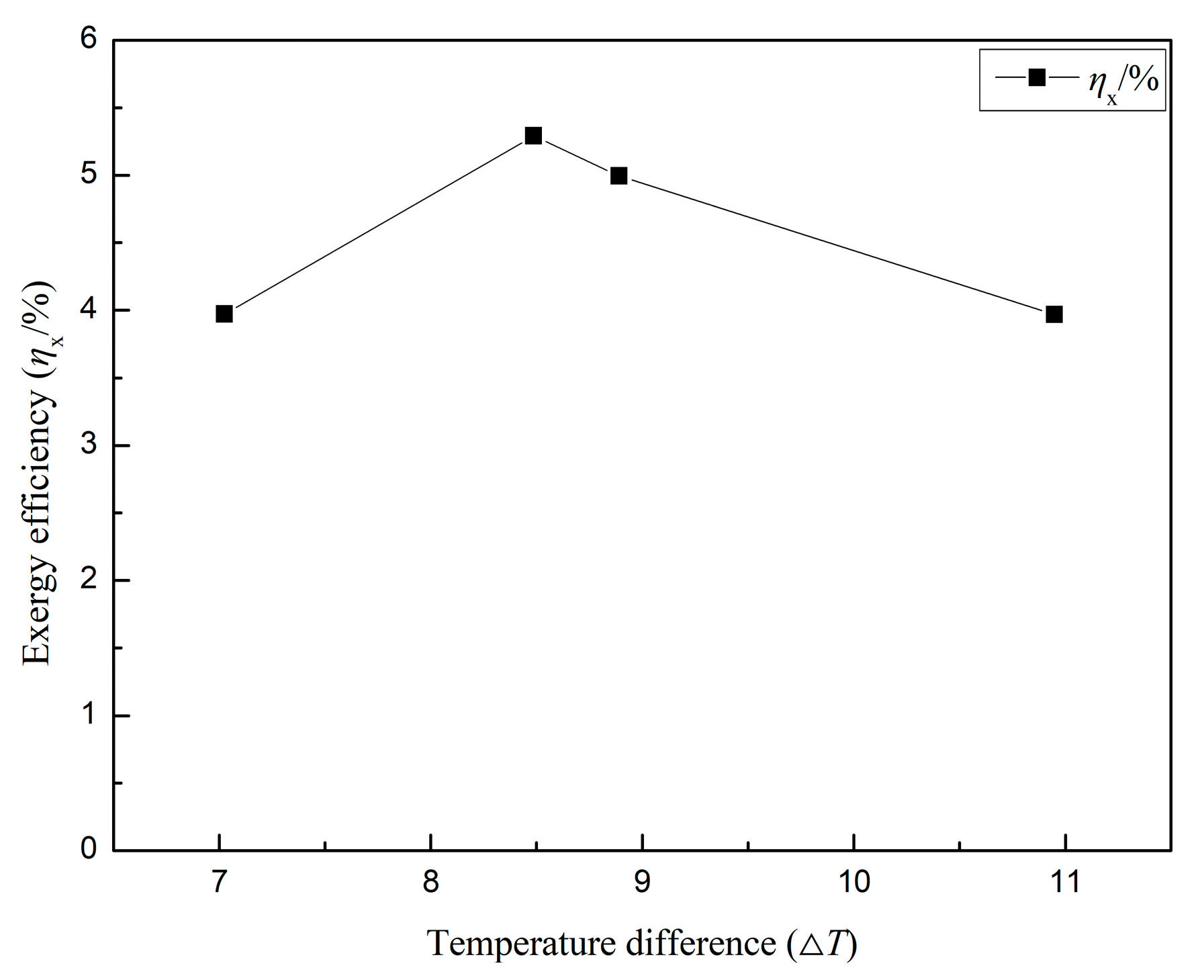
  • Increasing the temperature difference between the hot and cold sides of CLVTEG led to an initial increase and subsequent decrease in both working efficiency and exergy efficiency. The addition of copper foam improved heat conduction and disturbance within the channel, resulting in a more uniform temperature distribution and reduced temperature difference. This allowed for better heat utilization by the thermoelectric module, leading to higher efficiencies. The addition of 10 PPI copper foam yielded the best performance, and further increases in temperature difference had diminishing returns.
Overall, this study demonstrated the importance of considering both working efficiency and exergy efficiency when evaluating the performance of a thermoelectric generator. The addition of copper foam in the CLVTEG central area improved its working efficiency and exergy efficiency by enhancing heat transfer, temperature distribution, and utilization of the temperature difference. These findings contribute to the optimization of thermoelectric generator design for cold chain logistics transport vehicles and provide insights for improving energy conversion efficiency in low-grade energy utilization. The future work following this study includes: 1. Conducting simulations of the experimental model and cross validating the results with the experimental findings; 2. Finding the optimal copper foam PPI that makes a balance between system working efficiency, exergy efficiency, pressure drop loss, and other factors relevant to CLVTEG; 3. Investigating methods to further enhance the heat transfer enhancement capability of the CLVTEG hot side.

Author Contributions

Y.L. designed this work, designed and established the CLVTEG, and wrote and edited this manuscript. Y.F. performed the calculations, performed the data curation, and analyzed the experimental data. All authors have read and agreed to the published version of the manuscript.

Funding

This research received no external funding.

Data Availability Statement

All data used are reported here and/or in the cited literature sources.

Conflicts of Interest

The authors declare no conflict of interest.

References

  1. Sharifi, S.; Sedaghat, M.; Farhadi, P.; Ghadimi, N.; Taheri, B. Environmental economic dispatch using improved artificial bee colony algorithm. Evol. Syst. 2017, 8, 233–242. [Google Scholar] [CrossRef]
  2. Taheri, B.; Aghajani, G.; Sedaghat, M. Economic dispatch in a power system considering environmental pollution using a multi-objective particle swarm optimization algorithm based on the Pareto criterion and fuzzy logic. Int. J. Energy Environ. Eng. 2017, 8, 99–107. [Google Scholar] [CrossRef] [Green Version]
  3. He, W.; Zhang, G.; Zhang, X.; Ji, J.; Li, G.; Zhao, X. Recent development and application of thermoelectric generator and cooler. Appl. Energy 2015, 143, 1–25. [Google Scholar] [CrossRef]
  4. Pourkiaei, S.M.; Ahmadi, M.H.; Sadeghzadeh, M.; Moosavi, S.; Pourfayaz, F.; Chen, L.; Yazdi, M.A.P.; Kumar, R. Thermoelectric cooler and thermoelectric generator devices: A review of present and potential applications, modeling and materials. Energy 2019, 186, 115849. [Google Scholar] [CrossRef]
  5. Champier, D. Thermoelectric generators: A review of applications. Energy Convers. Manag. 2017, 140, 167–181. [Google Scholar] [CrossRef]
  6. Amatya, R.; Ram, R.J. Solar thermoelectric generator for micropower applications. J. Electron. Mater. 2010, 39, 1735–1740. [Google Scholar] [CrossRef]
  7. Yan, J.; Liao, X.; Yan, D.; Chen, Y. Review of micro thermoelectric generator. J. Microelectromechanical Syst. 2018, 27, 1–18. [Google Scholar] [CrossRef]
  8. Niu, X.; Yu, J.; Wang, S. Experimental study on low-temperature waste heat thermoelectric generator. J. Power Sources 2009, 188, 621–626. [Google Scholar] [CrossRef]
  9. Kim, S.J.; We, J.H.; Cho, B.J. A wearable thermoelectric generator fabricated on a glass fabric. Energy Environ. Sci. 2014, 7, 1959–1965. [Google Scholar] [CrossRef]
  10. Jouhara, H.; Żabnieńska-Góra, A.; Khordehgah, N.; Doraghi, Q.; Ahmad, L.; Norman, L.; Axcell, B.; Wrobel, L.; Dai, S. Thermoelectric generator (TEG) technologies and applications. Int. J. Thermofluids 2021, 9, 100063. [Google Scholar] [CrossRef]
  11. Karri, M.A.; Thacher, E.F.; Helenbrook, B.T. Exhaust energy conversion by thermoelectric generator: Two case studies. Energy Convers. Manag. 2011, 52, 1596–1611. [Google Scholar] [CrossRef]
  12. Luo, D.; Yan, Y.; Chen, W.-H.; Yang, X.; Chen, H.; Cao, B.; Zhao, Y. A comprehensive hybrid transient CFD-thermal resistance model for automobile thermoelectric generators. Int. J. Heat Mass Transf. 2023, 211, 124203. [Google Scholar] [CrossRef]
  13. Li, P.; Cai, L.; Zhai, P.; Tang, X.; Zhang, Q.; Niino, M. Design of a concentration solar thermoelectric generator. J. Electron. Mater. 2010, 39, 1522–1530. [Google Scholar] [CrossRef]
  14. He, W.; Wang, S.; Lu, C.; Zhang, X.; Li, Y. Influence of different cooling methods on thermoelectric performance of an engine exhaust gas waste heat recovery system. Appl. Energy 2016, 162, 1251–1258. [Google Scholar] [CrossRef]
  15. Lu, C.; Wang, S.; Chen, C.; Li, Y. Effects of heat enhancement for exhaust heat exchanger on the performance of thermoelectric generator. Appl. Therm. Eng. 2015, 89, 270–279. [Google Scholar] [CrossRef]
  16. Zhao, Y.; Wang, S.; Ge, M.; Liang, Z.; Liang, Y.; Li, Y. Performance investigation of an intermediate fluid thermoelectric generator for automobile exhaust waste heat recovery. Appl. Energy 2019, 239, 425–433. [Google Scholar] [CrossRef]
  17. He, W.; Wang, S.; Zhang, X.; Li, Y.; Lu, C. Optimization design method of thermoelectric generator based on exhaust gas parameters for recovery of engine waste heat. Energy 2015, 91, 1–9. [Google Scholar] [CrossRef]
  18. Zhao, Y.; Wang, S.; Ge, M.; Li, Y.; Liang, Z. Analysis of thermoelectric generation characteristics of flue gas waste heat from natural gas boiler. Energy Convers. Manag. 2017, 148, 820–829. [Google Scholar] [CrossRef]
  19. Li, Y.; Wang, S.; Zhao, Y.; Lu, C. Experimental study on the influence of porous foam metal filled in the core flow region on the performance of thermoelectric generators. Appl. Energy 2017, 207, 634–642. [Google Scholar] [CrossRef]
  20. Ge, M.; Zhao, Y.; Li, Y.; He, W.; Xie, L.; Zhao, Y. Structural optimization of thermoelectric modules in a concentration photovoltaic–thermoelectric hybrid system. Energy 2022, 244, 123202. [Google Scholar] [CrossRef]
  21. He, W.; Wang, S.; Li, Y.; Zhao, Y. Structural size optimization on an exhaust exchanger based on the fluid heat transfer and flow resistance characteristics applied to an automotive thermoelectric generator. Energy Convers. Manag. 2016, 129, 240–249. [Google Scholar] [CrossRef]
  22. Zhao, Y.; Fan, Y.; Li, W.; Li, Y.; Ge, M.; Xie, L. Experimental investigation of heat pipe thermoelectric generator. Energy Convers. Manag. 2022, 252, 115123. [Google Scholar] [CrossRef]
  23. Zhao, Y.; Wang, S.; Ge, M.; Liang, Z.; Liang, Y.; Li, Y. Performance analysis of automobile exhaust thermoelectric generator system with media fluid. Energy Convers. Manag. 2018, 171, 427–437. [Google Scholar] [CrossRef]
  24. Zhao, Y.; Wang, S.; Ge, M.; Li, Y.; Yang, Y. Energy and exergy analysis of thermoelectric generator system with humidified flue gas. Energy Convers. Manag. 2018, 156, 140–149. [Google Scholar] [CrossRef]
  25. He, W.; Wang, S.; Zhao, Y.; Li, Y. Effects of heat transfer characteristics between fluid channels and thermoelectric modules on optimal thermoelectric performance. Energy Convers. Manag. 2016, 113, 201–208. [Google Scholar] [CrossRef]
  26. Li, Y.; Wang, S.; Zhao, Y. Experimental study on heat transfer enhancement of gas tube partially filled with metal foam. Exp. Therm. Fluid Sci. 2018, 97, 408–416. [Google Scholar] [CrossRef]
  27. Zhao, Y.; Wang, S.; Ge, M.; Li, Y.; Liang, Z.; Yang, Y. Performance analysis of a thermoelectric generator applied to wet flue gas waste heat recovery. Appl. Energy 2018, 228, 2080–2089. [Google Scholar] [CrossRef]
  28. Ge, M.; Li, Z.; Zhao, Y.; Xuan, Z.; Li, Y.; Zhao, Y. Experimental study of thermoelectric generator with different numbers of modules for waste heat recovery. Appl. Energy 2022, 322, 119523. [Google Scholar] [CrossRef]
  29. Zhao, Y.; Lu, M.; Li, Y.; Ge, M.; Xie, L.; Liu, L. Characteristics analysis of an exhaust thermoelectric generator system with heat transfer fluid circulation. Appl. Energy 2021, 304, 117896. [Google Scholar] [CrossRef]
  30. Zhao, Y.; Wang, S.; Li, Y. Thermoelectric power generation using LNG cold energy and flue gas heat. Energy Procedia 2017, 105, 1932–1935. [Google Scholar] [CrossRef]
  31. Li, Y.; Wang, S.; Zhao, Y.; Yue, L. Experimental study on the effect of core flow heat transfer enhancement on the performance of TEG. Energy Rep. 2022, 8, 575–580. [Google Scholar] [CrossRef]
  32. Zhao, Y.; Lu, M.; Li, Y.; Wang, Y.; Ge, M. Numerical investigation of an exhaust thermoelectric generator with a perforated plate. Energy 2023, 263, 125776. [Google Scholar] [CrossRef]
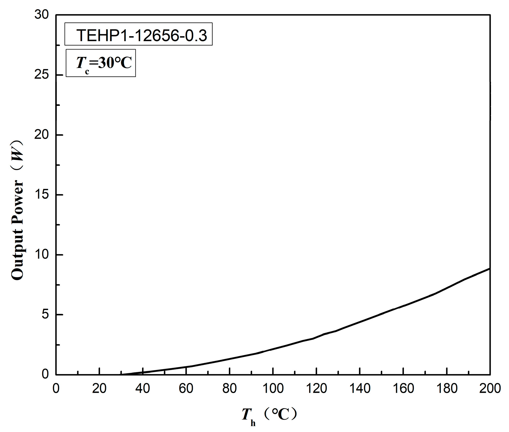
Figure 1. Performance of TEHP1-12656-0.3.
Processes 11 01782 g001
Figure 2. Schematic diagram of CLVTEG structure.
Processes 11 01782 g002
Figure 3. Schematic diagram of CLVTEG structure with added copper foam.
Processes 11 01782 g003
Figure 4. Copper foam with different PPI.
Processes 11 01782 g004
Figure 5. Output power of CLVTEG varies with external resistance.
Processes 11 01782 g005
Figure 6. Temperature difference and open circuit voltage of CLVTEG.
Processes 11 01782 g006
Figure 7. Influence of added copper foam on the heat transfer coefficient of CLVTEG.
Processes 11 01782 g007
Figure 8. Working efficiency of CLVTEG varies with external resistance.
Processes 11 01782 g008
Figure 9. Exergy efficiency of CLVTEG varies with external resistance.
Processes 11 01782 g009
Figure 10. Working efficiency of CLVTEG varies with temperature difference.
Processes 11 01782 g010
Figure 11. Exergy efficiency of CLVTEG varies with temperature difference.
Processes 11 01782 g011
Table 1. Basic parameters of thermoelectric module TEHP1-12656-0.3.
TEHP1
−12656
−0.3
Length
(mm)
Width
(mm)
Height
(mm)
Specific Conductance σ (S/m)Thermal
Conductivity κ (W/Mk)
Seebeck Coefficient α (V/K)Figure of Merit ZT (-)
565652.751.120.030.66
Table 2. CLVTEG size.
Length
/mm
Width
/mm
Height
/mm
Wall Thickness
/mm
high-temperature exhaust gas channel35070205
low-temperature cooling water channel35070205
Table 3. Basic parameters of each copper foam filling method.
MethodM0M1M2M3
PPI0102040
Porosity098%98%98%
Filling rate050%50%50%
Disclaimer/Publisher’s Note: The statements, opinions and data contained in all publications are solely those of the individual author(s) and contributor(s) and not of MDPI and/or the editor(s). MDPI and/or the editor(s) disclaim responsibility for any injury to people or property resulting from any ideas, methods, instructions or products referred to in the content.

