Article

Understanding the Impact of Sintering Temperature on the Properties of Ni–BCZY Composite Anode for Protonic Ceramic Fuel Cell Application

by
Nur Hanisah Hadi
1,
Mahendra Rao Somalu
1,*,
Abdullah Abdul Samat
2,
Wan Nor Anasuhah Wan Yusoff
1,
Andanastuti Muchtar
1,3,
Nurul Akidah Baharuddin
1,
Muhammed Ali Shaikh Abdul
1,
Jarot Raharjo
4,
Deni Shidqi Khaerudini
4,
Abdalla M. Abdalla
5 and
Abul Kalam Azad
6
1
Fuel Cell Institute, Universiti Kebangsaan Malaysia, Bangi 43600, Selangor, Malaysia
2
Faculty of Mechanical Engineering Technology, Universiti Malaysia Perlis (UniMAP), Pauh Putra Campus, Arau 02600, Perlis, Malaysia
3
Department of Mechanical and Manufacturing Engineering, Faculty of Engineering and Built Environment, Universiti Kebangsaan Malaysia, Bangi 43500, Selangor, Malaysia
4
Research Center for Advanced Materials, National Research and Innovation Agency (BRIN), Building 224, Puspiptek Area, South Tangerang 15314, Banten, Indonesia
5
Department of Mechanical Engineering, Faculty of Engineering, Suez Canal University, Ismailia 41522, Egypt
6
Faculty of Integrated Technologies, Universiti Brunei Darussalam, Jalan Tungku Link, Gadong, Bandar Seri Begawan BE 1410, Brunei
*
Author to whom correspondence should be addressed.
Processes 2023, 11(7), 1902; https://doi.org/10.3390/pr11071902
Submission received: 31 March 2023 / Revised: 29 May 2023 / Accepted: 13 June 2023 / Published: 24 June 2023
(This article belongs to the Section Energy Systems)

Abstract

:

Highlights

  • NiO–BCZY powder prepared by citrate sol–gel method has homogenous particles;
  • NiO–BCZY powder showed an average particle size of 51 ± 16 nm;
  • NiO–BCZY powder calcined at 1100 °C showed a cubic phase without any impurities;
  • The conductivity of anode sintered at 1200–1400 °C was 443–1124 S/cm at 800 °C;
  • Anode sintered at 1400 °C exhibited the lowest ASR of 1.165 Ω cm2 at 800 °C.

Abstract

Understanding the impact of sintering temperature on the physical and chemical properties of Ni-BaCe0.54Zr0.36Y0.1O3-δ (Ni-BCZY) composite anode is worthy of being investigated as this anode is the potential for protonic ceramic fuel cell (PCFC) application. Initially, NiO–BCZY composite powder with 50 wt% of NiO and 50 wt% of BCZY is prepared by the sol–gel method using citric acid as the chelating agent. Thermogravimetric analysis indicates that the optimum calcination temperature of the synthesised powder is 1100 °C. XRD result shows that the calcined powder exists as a single cubic phase without any secondary phase with the lattice parameter (a) of 4.332 Å. FESEM analysis confirms that the powder is homogeneous and uniform, with an average particle size of 51 ± 16 nm. The specific surface area of the calcined powder measured by the Brunauer–Emmett–Teller (BET) technique is 6.25 m2/g. The thickness, porosity, electrical conductivity and electrochemical performance of the screen-printed anode are measured as a function of sintering temperature (1200–1400 °C). The thickness of the sintered anodes after the reduction process decreases from 28.95 μm to 26.18 μm and their porosity also decreases from 33.98% to 26.93% when the sintering temperature increases from 1200 °C to 1400 °C. The electrical conductivities of the anodes sintered at 1200 °C, 1300 °C and 1400 °C are 443 S/cm, 633 S/cm and 1124 S/cm at 800 °C, respectively. Electrochemical studies showed that the anode sintered at 1400 °C shows the lowest area specific resistance (ASR) of 1.165 Ω cm2 under a humidified (3% H2O) gas mixture of H2 (10%) and N2 (90%) at 800 °C. Further improvement of the anode’s performance can be achieved by considering the properties of the screen-printing ink used for its preparation.

Graphical Abstract

1. Introduction

Solid oxide fuel cell (SOFC) is a high–efficiency electrochemical device that can directly convert the chemical energy of fuels (e.g., H2 and CH4) to electrical energy through an electrochemical reaction at high temperatures (500–1000 °C). Conventional solid oxide fuel cells (SOFCs) that conduct oxygen ions from the anode to the cathode side through oxygen-conducting electrolytes such as yttria-stabilised zirconia (YSZ), samarium doped ceria (SDC) and gadolinium doped ceria (GDC) suffer from several problems including the longer start-up time, fuel dilution at the anode side, material degradation and components incompatibility at high operating temperatures (800–1000 °C) [1]. Protonic ceramic fuel cell (PCFC) is one of the SOFC types that use a proton-conducting material (e.g., BaCeO3 and BaZrO3) as an electrolyte and it can show high performance even at low operational temperatures (400–750 °C) [2]. In PCFC, the proton passes through the proton-conducting electrolyte from the anode to the cathode side, thus resulting in the formation of water at the cathode side, which prevents fuel dilution issues. In the electrochemical oxidation of fuels, the anode holds significant importance as one of the crucial components. Hence, its properties are very critical in any operating condition. In this regard, the anode requires a material with a small mismatch in thermal expansion coefficient (TEC) with the electrolyte components (15–20%) to avoid micro cracks and delamination problems [3]. In addition, the anode must have sufficient porosity (20–40%) for hydrogen, water vapour and electron transfer [4]. The anode must also show a large triple phase boundary (TPB) length and good electrical conductivity for high electrochemical and catalytic activity. Moreover, the anode must show tolerance towards impurities such as sulphur and carbon [5].
Ni-based materials have been used extensively because of their great electrochemical catalysis for hydrocarbon fuel oxidation reactions [6]. In addition, Ni-based anodes are the famous choice of materials because of their low-cost and good mechanical strength [7]. Most of the conventional composite anode powders (e.g., NiO–YSZ, NiO–ScSZ, NiO–GDC, NiO–SDC) prepared by wet chemical method (WCM) generally require a powder calcination temperature of around 700–800 °C to obtain a pure phase. The fabricated anode films also require sintering temperatures in the range of 1300–1400 °C for good performance at SOFC operating conditions. However, the characteristics of anode composite powders used with proton-conducting electrolytes may require different preparation conditions to obtain a high-performance anode. At present, the Nickel cermet perovskite composite materials such as Ni–BaCe0.54Zr0.36Y0.1O3-δ (Ni–BCZY) have gained great attention for application as the anode in PCFCs [8]. This anode can be used with BCY and BCZY electrolytes for operation at intermediate temperatures (600–800 °C) [9,10,11]. These electrolytes have good chemical stability in both H2O and CO2 environments and high protonic conductivity at intermediate temperatures [12,13]. However, the characteristics of Ni–BCZY, such as fabrication condition, microstructure, electrical conductivity and electrochemical performance, need to be understood clearly for PCFC application. To the best of our knowledge, there is no clear report on the relationship between the sintering condition and the properties of the anode. The sintering condition is commonly dependent on the morphology of the synthesised powder, such as particle size distribution and surface area. Hence, optimum sintering condition is very crucial to improve the electrochemical oxidation of fuel at the anode side. Anode materials have been synthesised by various techniques such as ball milling, solid-state reaction (SSR), template-based synthesis, sol–gel, co-precipitation, hydrothermal and solvothermal, and combustion. Different preparation methods lead to different properties of the prepared materials and consequently affect the sintering condition and performance of the fabricated anode. It is well known that the mechanical mixing of NiO and electrolyte is a simple and economical method to produce NiO–electrolyte composite anode. However, this method leads to contamination, inhomogeneous powder distribution, and poor electrical and electrochemical performance of the resultant anode. Instead of simply mixing NiO and electrolyte materials by ball milling, this study synthesises the anode composite by mixing all the raw materials together using the wet chemical method (WCM). Thus, sol–gel, a famous WCM, was used in this study to synthesise a high purity and homogenous NiO–BaCe0.54Zr0.36Y0.1O3-δ (NiO–BCZY) nano-sized powder [14,15].
Thus, the present work focused on synthesising NiO–BCZY anode composite materials by the citrate sol–gel method [16,17], followed by characterisation to determine the phase formation, microstructure and morphology of the powder. The powder calcined at the best calcination temperature was used to fabricate symmetrical anode cells by screen-printing on the BCY electrolyte pellets. Then, the screen-printed anodes were sintered at temperatures between 1200 °C and 1400 °C for 3 h, followed by microstructure, electrical conductivity and electrochemical performance evaluation. This evaluation could enhance the understanding of the material characteristics for further application in PCFC.

2. Materials and Method

2.1. Powder Preparation

Herein, precursor materials with purity >99% as received were used to synthesise NiO–BaCe0.54Zr0.36Y0.1O3-δ (NiO–BCZY) anode composite powder using the citrate sol–gel method [18]. According to stoichiometric ratio, 2.164 g of barium nitrate, Ba(NO3)2 (99%, Acros Organics, Geel, Belgium); 1.942 g of cerium (III) nitrate hexahydrate, Ce(NO3)3·6H2O (99.5%, Acros Organics, Geel, Belgium); 0.689 g of zirconyl (lV) nitrate hydrate, ZrO(NO3)2·6H2O (99.5%, Acros Organics, Geel, Belgium); 0.317 g of yttrium (III) nitrate hexahydrate, Y(NO3)3·6H2O (99.9%, Acros Organics, Geel, Belgium); and 9.734 g of nickel (II) nitrate hexahydrate, Ni(NO3)2·6H20 (99%, Acros Organics, Geel, Belgium), were dissolved in 150 mL of deionised water in order to produce 5 g of NiO–BCZY anode composite powder. The weight ratio of NiO to BCZY in the synthesised powder was 1:1. Then, the solution was mixed at room temperature until a clear green solution was visible. Subsequently, 205.05 g of citric acid was slowly added to the mixture as a complexing agent. The amount of citric acid used was based on the stoichiometric molar ratio of 1.5 to 1 of the total metal nitrate salts. Afterward, ammonium hydroxide solution, NH4OH (25% assays, EMSURE®, Sigma–Aldrich, Darmstadt, Germany), was added drop by drop until the pH of the solution reached nearly 7.0. Then, the temperature was increased to 120 °C for several hours and adjusted slowly by 15 °C/5 min until 325 °C to obtain a viscous gel. Moreover, the beaker containing the gel was covered with aluminium foil and pre-calcined in an oven at 200 °C for 12 h with a heating and cooling rate of 10 °C/min. Next, the resultant black ash was grounded in an agate mortar. An early thermogravimetric analysis (TGA) was conducted to decide the starting temperature for the calcination process before calcining the grounded powder. Afterward, the powder was calcined at 1100 °C for 6 h in a furnace, and this calcination temperature was sufficient to preserve the phase of the composite formed. The comparable calcination temperature was also recommended for the similar anode composite powder synthesised by solid-state reaction and ball milling methods [19,20].

2.2. Physicochemical Characterisation of Synthesised Powder

A thermogravimetric analyser (TGA, Pyris Diamond TG/DTG analyser, PerkinElmer, Wellesley, MA, USA) was used to analyse the weight loss and thermal decomposition behaviour of the prepared powder. The analysis was performed in synthetic air with a flow rate of 100 mL/min at a temperature ranging from 30 °C to 1000 °C with a heating rate of 10 °C/min.
Moreover, analysis of phase identification and structural and physical properties of calcined powders was performed on an X-ray diffractometer (XRD, D8–Advance, Bruker, Billerica, MA, USA) using Cu–Kα radiation source (λ = 0.15406 nm). The scanning range (2θ) was varied between 20° and 80° in the step size of 0.02°. Interplanar spacing (d) was calculated using Equation (1).
d = λ / 2 sin θ
where λ is the wavelength of X-rays (Cu-Kα = 0.15406 nm), θ is the Bragg angle in radian, and hkl are the Miller Indices picked from the highest peak in the XRD pattern. Lattice parameter (a) was calculated using Equation (2).
a = d   [   ( h 2 + k 2 + l 2 )   ]
Scherrer’s equation, as shown in Equation (3), was used to calculate the crystallite size (Dxrd). In this equation, k is a factor of dimensionless shape (spherical shape = 0.9), and β refers to the corrected full width at half maximum (FWHM) [21].
D x r d = k λ / ( β cos θ )
The density (ρ) of the calcined powder was calculated using Equation (4) [22]. n is the number of atoms per unit cell; for a cubic structure, which is n = 1, Mw refers to the molecular weight of the NiO–BCZY (376.634 g mol−1), and NA is the Avogadro’s number (6.022 × 10²³ mol−1). Note that a3 is equal to unit cell volume, V.
ρ = ( n × M w ) / ( a 3 × N A )
In addition, a field emission scanning electron microscope (FESEM, ZEISS MERLIN Compact, Oberkochen, Germany) was used to examine the microstructure and surface morphology of the powders. Moreover, the composition of each material in the powders was evaluated by energy-dispersive X-ray spectroscopy (EDX, JEOL–S100, Akishima, Japan) fitted to the FESEM. The mapping technique was used to detect the existence of the main elements, which were nickel (Ni), barium (Ba), cerium (Ce), zirconium (Zr) and yttrium (Y). Moreover, the particle size of the powders was measured on the captured FESEM images using the ImageJ software (Version 1.52g). Particle size distribution analysis was performed using a particle size analyser (Zetasizer Nanoseries, Malvern Instruments, Inc., Malvern, UK).
The specific area of the calcined powder was measured by surface area system (Micromeritics, ASAP 2020, Norcross, GA, USA) using Brunauer–Emmett–Teller (BET) technique. The sample was degassed at 110 °C for 10 h to remove any water or contaminants in the sample before the analysis. The value of BET surface area (SBET) was used to calculate the average particle size (DBET) of the powder according to Equation (5) [23], with ρ representing the theoretical density of the powder:
D B E T = 600 ρ · S B E T

2.3. Fabrication of Anode Screen–Printing Ink

The ingredients used to prepare the NiO–BCZY screen–printing ink are listed in Table 1. The final solid content of the ink was 70 wt% (26 vol%). The required amount of dispersant was calculated by multiplying its coverage area (2.5 mg/m2) with the measured BET surface area of the cermet powder. The amount of the binder needs to be more than 1 wt% of the powder to improve the particle network and porosity of the electrode after binder burnout [24].
After preparing the ingredients, the prepared anode composite powder was ball-milled for 24 h with the dispersant (Hypermer KD9) and acetone as the solvent. Then, the powder was dried in an oven at 90 °C for 24 h. Afterward, the powder was sieved properly and mixed with the vehicle. The vehicle was prepared by mixing both binder (ethyl cellulose binder, N7 grade) and solvent (terpineol, Sigma-Aldrich, Darmstadt, Germany) on a hot plate at 45 °C while stirring. The vehicle is a liquid mixture of the binder and the solvent with an appropriate composition (Table 1), as suggested by [25]. Subsequently, the anode powder was mixed and grounded with the prepared vehicle for 10 min. Finally, the mixture was milled using a triple-roll mill (EXAKT 80E, EXAKT Technologies, Inc., Norderstedt, Germany) to produce a homogeneous ink.

2.4. Electrochemical Characterisation of Anode Symmetrical Cells

Y-doped barium cerate, BaCe0.9Y0.1O3-δ (BCY) electrolyte powder was prepared using a solid-state reaction method and followed by calcination at 1300 °C for 3 h. After the powder was sieved, it was pressed into pellets with a diameter of 25 mm using a manual pressing machine (Carver, Inc., Wabash, In, USA). Then, the pellets were sintered at 1600 °C for 5 h to produce dense pellets. Afterward, the fabricated anode slurry was screen-printed onto both sides of the polished pellets to produce NiO–BCZY/BCY/NiO–BCZY anode symmetrical cells. Subsequently, a semi-manual screen printer (SMTech 90 Series) was used to deposit the slurry onto the surface of the pellets. The screen-printed films have a surface area of 1 cm2. Lastly, the printed anode films were sintered in a furnace at three different temperatures, which were 1200 °C, 1300 °C and 1400 °C for 3 h. Then, the sintered films were heated from room temperature to 800 °C under a nitrogen atmosphere. At 800 °C, the atmosphere was changed to a humidified (3% H2O) gas mixture of H2 (10%) and N2 (90%) for a duration of 2 h to start the reduction process. The gas mixture was maintained until the temperature decreased to room temperature to prevent reoxidation. This reduction process is very important to ensure the anode (Ni–BCZY) is electrically conductive. The microstructure of the cross-section and surface of the symmetrical cells after the reduction process was characterised using a field emission secondary electron microscope (FESEM, ZEISS Merlin, Oberkochen, Germany). The thicknesses and porosity of the reduced anode films were analysed using ImageJ software (Version 1.52g).

2.4.1. Electrical Conductivity Measurement

The measurement of electrical conductivity was performed under a flow of humidified (3% H2O) gas mixture of H2 (10%) and N2 (90%) from 800 °C down to 500 °C. The conductivity was measured via the four-point van der Pauw method, in which the symmetrical cell was placed into a sample holder with platinum wires attached to the four probes. The power supply applied an electrical current source of 0.10 A, and the output voltage was recorded to obtain the resistance. The following equations were used to calculate the average resistance, Rave (Ω); sheet resistance, Rs (Ω); and the DC electrical conductivity, σ D C (S/cm) [26].
R a v e =   R 12 + R 23 + R 34 + R 41 4
R s = ( π l n 2 ) ( R a v e )
σ D C = 1 R s l
where R12, R23, R34 and R41 are the values of resistances calculated from the measured voltages at 0.10 A current through the four probes. l is the thickness of the film (cm).

2.4.2. Electrochemical Performance Measurement

The electrochemical performance of the symmetrical cell was analysed via electrochemical impedance spectroscopy (EIS) under a flow of humidified (3% H2O) gas mixture of H2 (10%) and N2 (90%) from 800 °C down to 500 °C using a home-built test rig. The EIS was measured with a potentiostat (Autolab PGSTAT302N, Eco Chemie, Utrecht, The Netherlands) combined with a frequency response analyser (FRA). In addition, the EIS was measured in the frequency range of 0.1–1 MHz at an applied voltage amplitude of 20 mV. Finally, the data collected from the testing were analysed and plotted as Nyquist plots using Nova 2.1.4 software. Moreover, the polarization resistance (Rp) of the anode was analysed using an electrical circuit fitting.

3. Results and Discussion

3.1. Physicochemical Characterisation

Figure 1 shows the thermogravimetric (TG) and derivative thermogravimetric (DTG) curves of the as-synthesised NiO–BCZY powder. The TG/DTG curve represents the multistage thermal decomposition behaviour of the powder with three stages of weight loss. Initial weight loss is observed at stage 1 accompanied by an endothermic peak in the DTG plot in the temperature region between 31 °C and 206 °C with a weight loss of ~5.5% because of dehydration of the adsorbed water and loss of volatile components [27]. In stage 2, which is in the region between 206 °C and 757 °C, major weight loss is observed at ~41.7%, and this is supported by endothermic peaks in the DTG plot. A slight artifact (circled in green) is expected because of a mechanical shock. This major loss is observed as a result of the decomposition of nitrates and organic compounds such as citric acid (CA) in the powder [28]. Moreover, the third stage shows a minimal weight loss, which is ~7.0%, with one endothermic peak in the DTG curve. This is because of the combustion of the carbon residue. However, almost no weight loss was observed in the DTG plot after stage 3, and the line became plateau, thus indicating the beginning process of crystallization and phase formation. The TG machine can only be operated up to 1000 °C, and thus we decided to refer to a study reported by [18] to determine any other losses beyond 1000 °C. No further losses were detected based on the study; therefore, 1100 °C was chosen as the calcination temperature for NiO–BCZY powder.
Figure 2 illustrates the differential scanning calorimetry (DSC) plot. Therein, DSC was carried out to ascertain the calcination temperature. Based on the figure, the transition shows a discontinuity in the baseline. As the temperature increases, the composite might correspond to the heat of melting and come out with an endothermic peak before the crystallization process [29]. The exothermic peak at ~291 °C correlates with the gaining of energy by the system for decomposition to take place [30]. The melting process occurs again and repeats the crystallization process between 500 °C and 750 °C, as shown by the exothermic peak. The DSC plot also shows that there is no significant weight loss occurred above 850 °C.
Figure 3 shows the XRD pattern of NiO–BCZY powder calcined at 1100 °C. No impurities were observed, and other phases were in the obtained data, thus proving that the powder is high in purity. The pattern shows a face-centred cubic (FCC) structure with a space group of Fm-3m. The BCZY pronounced peaks were indexed using the following Miller indices: (110), (111), (200), (211), (220), (222) and (300) using the Joint Committee on Powder Diffraction Standards (JCPDS) card of Ba(Ce,Zr)O3 as reference (card no. 010892485 [18]). Moreover, pronounced peaks for NiO were (111), (200) and (220) based on the JCPDS card of nickel oxide (card no. 010780643 [18]). The calculated lattice parameter (a) of NiO–BCZY is 4.332 Å, which is comparable to the reference value of 4.335 Å [18]. The estimated density (ρ) of the anode powder is 7.696 gcm−3, while the estimated crystallite size (Dxrd) for NiO and BCZY based on the XRD peaks are 10.04 nm and 47.67 nm, respectively. The lattice parameter and density of NiO, BCZY and JCPDS reference are summarised in Table 2.
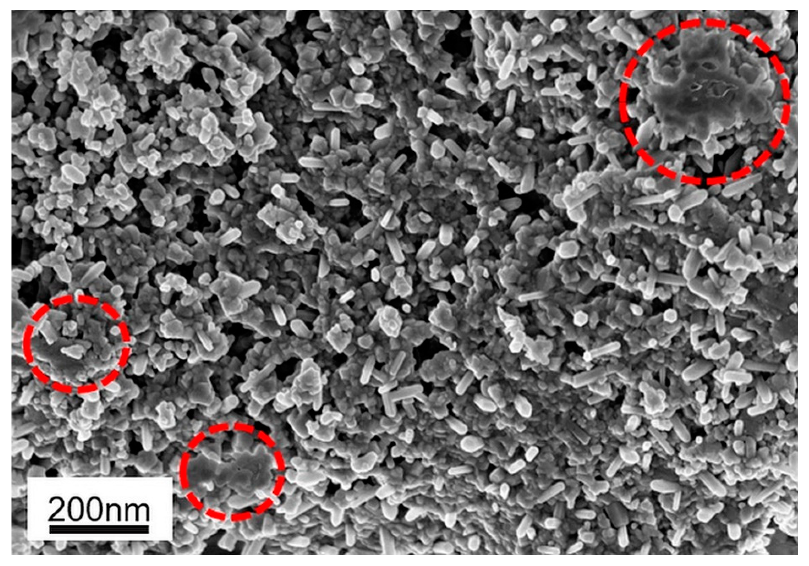
Figure 4 depicts the morphology of the NiO–BCZY composite powder after calcining at 1100 °C for 6 h. The morphology of the powder was referred to in previous studies that used the same material but with higher calcination temperatures [18,31]. The average particle size measured from the FESEM images (DFESEM) is 51 ± 16 nm. Based on the images, the powder showed a homogenous distribution with a slight agglomeration (in red dotted circles) caused by high calcination temperature. Figure 5 shows the EDX spectrum with information on the weight percentage (wt%) and the mole ratio of each element. The spectrum shows the presence of nickel (Ni), barium (Ba), cerium (Ce), zirconium (Zr) and yttrium (Y) in the powder. This indicates that the synthesised powder by the citrate sol–gel method is pure without any impurities. Table 3 displays the estimated elemental composition of NiO–BCZY powder calculated using the EDX data. The mole ratio of the powder was slightly different compared to the nominal mole ratio. It was because the analysis was performed in a small coverage area, and the composition might not be the same everywhere [32]. Hence, this analysis was conducted in five different areas to obtain an average composition for each element with reduced deviation. Based on the EDX and XRD results, no foreign peak exists in both analyses, thus proving that the citrate sol–gel method can produce a high-purity powder. The mapping analysis was also conducted to support the result of powder homogeneity. The result is shown in Figure 6. From the mapping, purple, blue, yellow, green and red indicate the presence of Ni, Ba, Ce, Zr and Y elements, respectively. The mapping shows that all elements in the synthesised powder are homogeneously dispersed. The homogeneity of the elemental distribution is very critical to produce a high–performance anode.
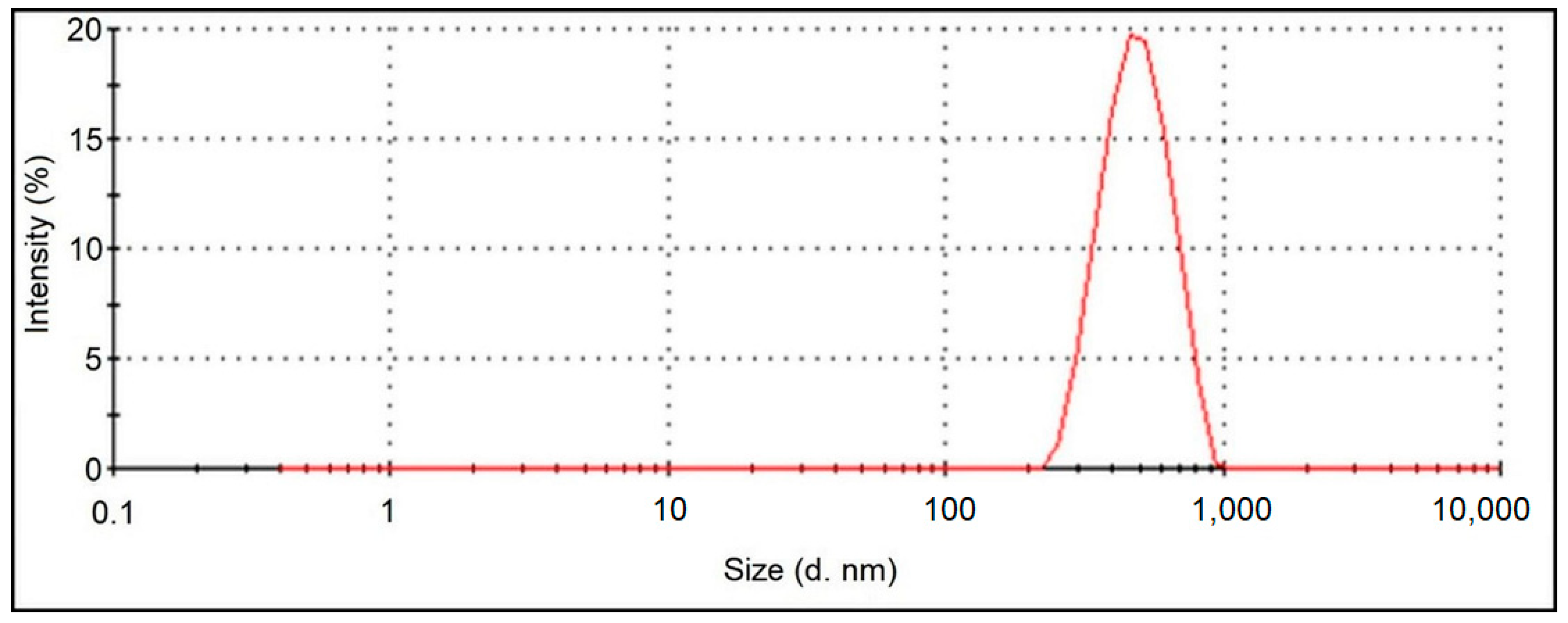
The particle size distribution of the calcined NiO–BCZY anode composite powder is shown in Figure 7. The distribution shows a single mode distribution with the particle distribution in the range of 200–1000 nm and an average particle size of ~501.2 nm. The distribution of the synthesised powder is narrower and finer compared to the anode powder synthesised by other conventional methods in the literature [33]. The narrow unimodal distribution can be attributed to a homogenous powder with reduced agglomeration [34]. This result is also in agreement with the morphology of the powder shown in Figure 4. This result further supports that the citrate sol–gel method is a potential method to produce a homogeneous anode power. The BET surface area (SBET) of the calcined powder was 6.25 m2/g, while the corresponding average particle size (DBET) was 124.74 nm. However, there are no current data on the BET surface area of this specific material (NiO–BCZY) to compare with.

3.2. Characterisation of Anode Film

The FESEM images of the surface and cross-section of the reduced Ni–BCZY anode films sintered at different temperatures are presented in Figure 8. The thickness and porosity of the films after reduction are tabulated in Table 4. The films are uniformly printed onto the electrolyte pellets, and no delamination is observed. Moreover, the surface porosity for the samples is in the acceptable range of 20–40%. As expected, the porosity of films decreases because of increasing grain growth as the sintering temperature increases. The film thickness also decreases as the sintering temperature increases, as demonstrated in cross-sectional micrographs. This is attributed to the densification process [35]. The densification affects the electrical conductivity and electrochemical performance of the anode through the improved Ni–Ni and BCZY–BCZY network in anode films. Thus, an appropriate sintering temperature should be determined based on the electrical and electrochemical performance.

3.2.1. Electrical Conductivity of the Anode

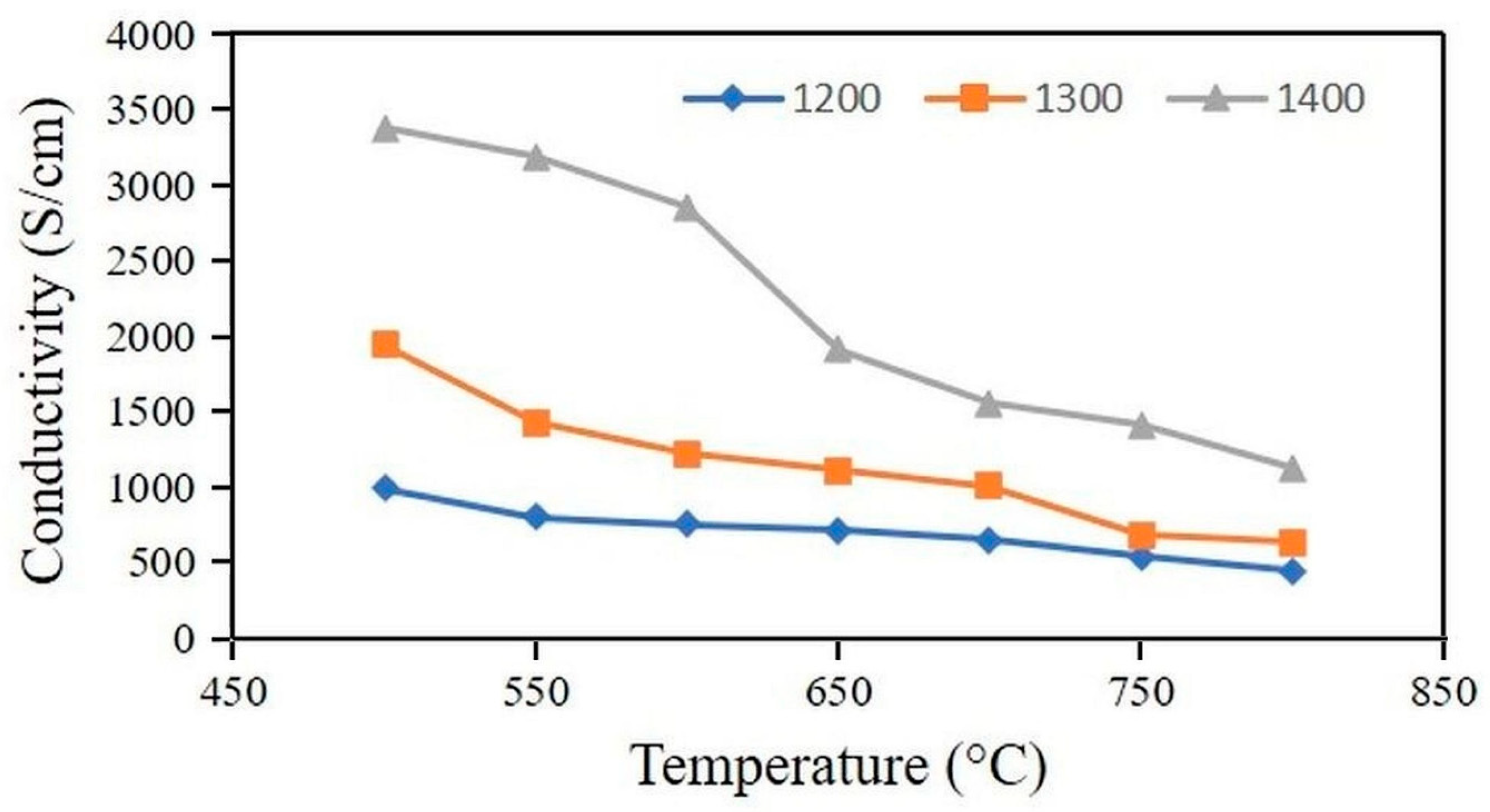
The DC electrical conductivity, σ D C of the reduced Ni–BCZY anode films sintered at 1200 °C, 1300 °C and 1400 °C is presented in Figure 9. Based on the figure, the electrical conductivity decreases with increasing temperature. This indicates that the conductivity of the anode is dominated by electronic conductivity and consistent with the metallic behaviour [36]. The conductivity of the anodes sintered at 1200 °C, 1300 °C and 1400 °C are 443 S/cm, 633 S/cm and 1124 S/cm at 800 °C, respectively. These conductivities met the general requirement of conductivity for an anode (>100 S/cm). It is clear that the anode sintered at a higher temperature has a higher conductivity because of the increased Ni–Ni particle connectivity resulting from grain growth, as confirmed in Figure 8. The improved particle connectivity is very important to improve the electrochemically active sites in the anode. All the anodes fulfilled the minimum required electrical conductivity of 100 S/cm at 800 °C and, therefore, are suitable for PCFC application. Sawant et al. [36] reported the conductivity of porous Ni–BCY (~40%) as 745 S/cm at 700 °C. This conductivity was different from the conductivity of the Ni–BCZY anode reported in this study. This difference indicates that the anode powder preparation method, Ni content, quality of the fabricated anode and sintering condition affect the overall properties of an anode. The anode films fabricated by the screen-printing technique in this study showed a uniform surface morphology and are consistent with several reported studies [25,37,38]. It is worth noting that an anode with a higher porosity may have a lower conductivity as a result of reduced Ni–Ni particle networks within the fabricated anode [39]. Thus, it is important to consider both electrical conductivity and electrochemical performance to determine the best fabrication condition for an anode.

3.2.2. Electrochemical Performance of Anode

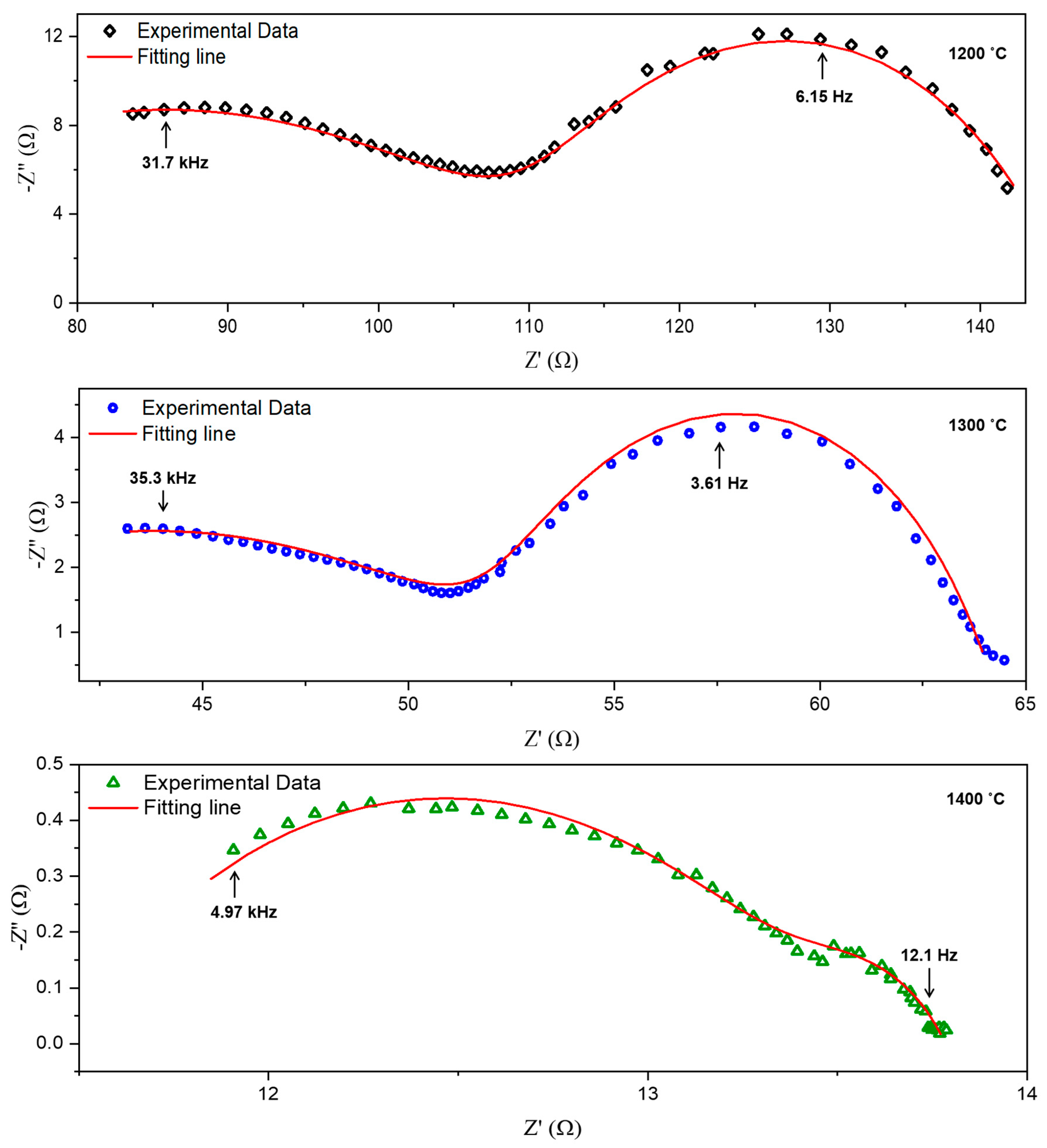
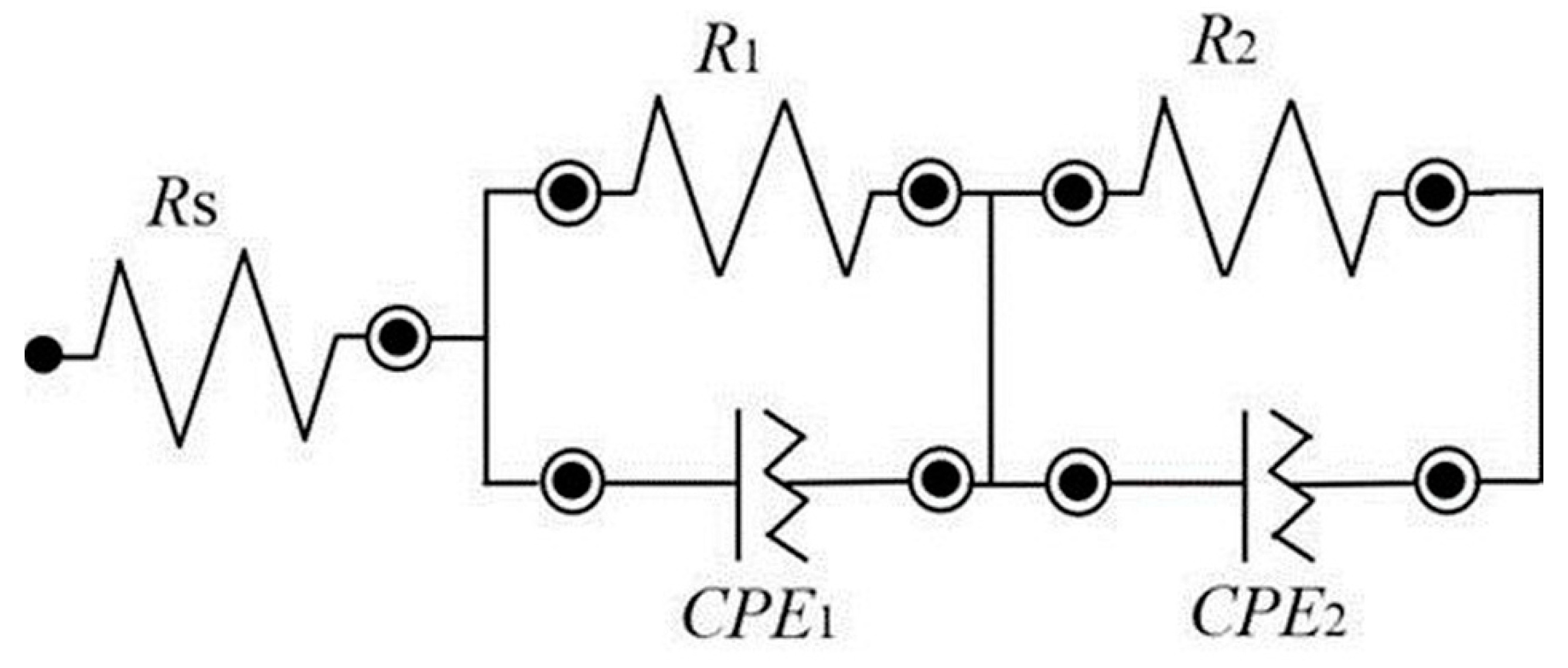
Figure 10 shows the fitted electrochemical impedance spectra (EIS) of the Ni–BCZY/BCY/Ni–BCZY symmetrical cell measured at 800 °C under a humidified (3% H2O) gas mixture of H2 (10%) and N2 (90%). The fitting was performed based on the equivalent electrical circuit that consists of resistance (R) and constant phase element (CPE), as illustrated in Figure 11. The total electrode polarization resistance, Rp (Ω), and the area–specific resistance (ASR) can be calculated from the spectra by the following equations [40]:
R p = R 1 + R 2
A S R = R p A / 2
where R1 and R2 are the polarisation resistances when the process of charge transfer and gas diffusion occurs [41,42]. In this equation, A represents the active working area of the anode (1 cm2). The impedance spectra contained two arcs in which the capacitances were >10−5 F and <10−6 F, related to the reaction of the anode and the reaction of the electrolyte, respectively [43]. Therefore, only resistance from the response of the electrode was used to calculate the ASR from Equation (10). Hence, for the anodes that sintered at 1200 °C and 1300 °C, only R2 was used to calculate the ASR, while for the anode sintered at 1400 °C, both R1 and R2 were used to calculate the ASR. The pattern observed in the plot was identical to that of the previous studies [41,44]. Based on the fitting process, the characteristic frequency (fmax) and capacitance (C) were calculated by the following equations [45]:
C = Y 1 n · R 1 n 1
f m a x = 1 2 π · R · C
where Y and n are the parameters related to the CPEs while R is the resistance. The calculated values of C, fmax, R1, R2 and ASR are tabulated in Table 5. Rs is referred to the resistance of connecting wire or noise, while Rp is identified as electrode response with a capacitance value of <10−6 F [46].
The ASR value of the anode sintered at 1400 °C is 1.165 Ω cm2, which is in close proximity to the generally recommended value for an electrode (<1.0 Ω cm2). It is noteworthy that this value is significantly influenced by the properties of the screen-printing ink used in the screen-printing process. According to several studies [24,25], the ASR value of the anode can be further decreased by enhancing the ingredients and rheology of the ink. This may be a plausible explanation for the marginally elevated ASR values obtained in this study. Thus, improving the ink’s characteristics could lead to a reduction in the ASR value of the anode. However, the ASR values for the anode sintered at 1200 °C and 1300 °C are higher than the anode sintered at 1400 °C. This result indicates that the anodes sintered at low sintering temperatures possessed poor particle connectivity and were consistent with their microstructure shown in Figure 8. As a result, the anodes sintered at 1200 °C and 1300 °C exhibited a high polarisation resistance. According to Jais et al. [37], the thickness of the anode layer must not exceed 35 µm to avoid high polarization resistance due to difficulty in the gas transportation to the electrochemically active sites. However, all the anode films in this study have a thickness less than the suggested thickness. The anode was not sintered at a temperature above 1400 °C to avoid Ba evaporation and grain growth [47]. Based on its electrical and electrochemical performance, the anode sintered at 1400 °C is expected to be acceptable for PCFC application, which is consistent with several previous studies, as shown in Table 6. However, the anode’s performance requires further improvement, which could be achieved by enhancing the properties of the prepared ink. It is worth noting that the anode’s performance depends on various factors, including the powder preparation method, anode preparation technique, fabrication conditions and reducing conditions. This explains why the anode prepared by the screen-printing technique in this study exhibited a slightly higher ASR value compared to other anodes in Table 6.

4. Conclusions

Composite anode powder of NiO–BaCe0.54Zr0.36Y0.1O3-δ (NiO–BCZY) was successfully prepared through the citrate sol–gel method. TGA analysis suggested the appropriate calcination temperature of the powder as 1100 °C to obtain a high purity power. The sizes of particles calculated by XRD, FESEM, PSA and BET analyses were 47.67 nm, 51 ± 16 nm, ~501.2 nm and 124.74 nm, respectively. The distribution of the elements in the powder was homogenous, as confirmed by EDX mapping. The porosities of reduced Ni–BCZY anodes sintered at 1200 °C, 1300 °C and 1400 °C were 33.98% ± 0.52, 29.47% ± 0.62 and 26.93% ± 0.65, respectively. Moreover, the conductivities of the anode sintered at 1200 °C, 1300 °C and 1400 °C were 443 S/cm, 663 S/cm and 1124 S/cm at 800 °C, respectively. The anode sintered at 1400 °C exhibited the lowest ASR of 1.165 Ωcm2 in a humidified (3% H2O) gas mixture of H2 (10%) and N2 (90%). Based on the electrical and electrochemical performance, the anode sintered at 1400 °C in this study is acceptable for PCFC application by considering the Ni growth and evaporation of Ba at high temperatures (>1500 °C). Further improvement of the anode’s performance can be achieved by considering the properties of the screen-printing ink used for its preparation. Additionally, investigating the anode’s tolerance towards carbon deposition and sulphur poisoning in hydrocarbon fuel is recommended.

Author Contributions

Data curation, N.H.H. and D.S.K.; Formal analysis, N.H.H., M.A.S.A. and J.R.; Funding acquisition, M.R.S.; Investigation, N.H.H. and W.N.A.W.Y.; Methodology, A.A.S.; Supervision, M.R.S., A.A.S., A.M. and N.A.B.; Validation, M.R.S. and A.M.A.; Writing—original draft, N.H.H.; Resources, A.K.A.; Writing—review and editing, M.R.S. and A.K.A. All authors have read and agreed to the published version of the manuscript.

Funding

This research was funded the Ministry of Higher Education Malaysia through the Fundamental Research Grant Scheme (FRGS) with the code of FRGS/1/2020/STG05/UKM/02/6 and Universiti Kebangsaan Malaysia via the Geran Universiti Penyelidikan (GUP) with the code of GUP-2021-076.

Data Availability Statement

The data presented in this study are available on request from the corresponding author.

Acknowledgments

The authors would like to acknowledge the facility support from the Centre for Research and Instrumentation Management (CRIM), UKM, Department of Applied Physics, UKM, Faculty of Engineering and Built Environment, UKM, as well as the Research Center for Advanced Materials, National Research and Innovation Agency (BRIN), Indonesia.

Conflicts of Interest

The authors declare that they have no conflict of interest. The authors declare that they have no known competing financial interests or personal relationships that could have appeared to influence the work reported in this paper.

References

  1. Xie, D.; Li, K.; Yang, J.; Yan, D.; Jia, L.; Chi, B.; Pu, J.; Li, J. High-Performance La0.5(Ba0.75Ca0.25)0.5Co0.8Fe0.2O3-δ Cathode for Proton-Conducting Solid Oxide Fuel Cells. Int. J. Hydrogen Energy 2021, 46, 10007–10014. [Google Scholar] [CrossRef]
  2. Liu, B.; Jia, L.; Chi, B.; Pu, J.; Li, J. A Novel PrBaCo2O5+σ-BaZr0.1Ce0.7Y0.1Yb0.1O3 Composite Cathode for Proton Conducting Solid Oxide Fuel Cells. Compos. B Eng. 2020, 191, 107936. [Google Scholar] [CrossRef]
  3. Kei Hoa, N.; Rahman, H.A.; Rao Somalu, M. Influence of Silver Addition on the Morphological and Thermal Characteristics of Nickel Oxide-Samarium Doped Ceria Carbonate (NiO-SDCC) Composite Anode. Int. J. Integr. Eng. 2018, 10, 196–201. [Google Scholar] [CrossRef]
  4. Miyamoto, K.; Koga, H.; Izumi, M.; Mizui, M.; Nishiguchi, H. Study on Fabrication of Anodes for SOFCs with 3D Printing Technology. ECS Trans. 2020, 96, 219–226. [Google Scholar] [CrossRef]
  5. Su, H.; Hu, Y.H. Progress in Low-Temperature Solid Oxide Fuel Cells with Hydrocarbon Fuels. Chem. Eng. J. 2020, 402, 126235. [Google Scholar] [CrossRef]
  6. Batool, R.; Gill, R.; Altaf, F.; Ahmad, M.A.; Raza, R.; Khan, M.A.; Hussain, F.; ur Rehman, Z.; Abbas, G. Structural and Electrochemical Study of Ba0.15Cu0.15Ni0.10Zn0.60 Oxide Anode for Low Temperature Solid Oxide Fuel Cell. J. Alloys Compd. 2019, 780, 653–659. [Google Scholar] [CrossRef]
  7. Escudero, M.J.; Yeste, M.P.; Cauqui, M.Á.; Muñoz, M.Á. Performance of a Direct Methane Solid Oxide Fuel Cell Using Nickel-Ceria-Yttria Stabilized Zirconia as the Anode. Materials 2020, 13, 599. [Google Scholar] [CrossRef] [Green Version]
  8. Tarutin, A.; Kasyanova, A.; Vdovin, G.; Lyagaeva, J.; Medvedev, D. Nickel-Containing Perovskites, PrNi0.4Fe0.6O3–δ and PrNi0.4Co0.6O3–δ, as Potential Electrodes for Protonic Ceramic Electrochemical Cells. Materials 2022, 15, 2166. [Google Scholar] [CrossRef]
  9. Ricote, S.; Kee, R.J.; Coors, W.G. Slip Casting and Solid-State Reactive Sintering of BCZY(BaCex Zr0.9−x Y0.1 O3−d)-NiO/BCZY Half-Cells. Membranes 2022, 12, 242. [Google Scholar] [CrossRef]
  10. Antonova, E.P.; Osinkin, D.A.; Bogdanovich, N.M. On a Variation of the Kinetics of Hydrogen Oxidation on Ni–BaCe(Y,Gd)O3 Anode for Proton Ceramic Fuel Cells. Int. J. Hydrogen Energy 2021, 46, 22638–22645. [Google Scholar] [CrossRef]
  11. Lv, H.; Jin, Z.; Peng, R.; Liu, W.; Gong, Z. BaCoxFe0.7-xZr0.3O3-δ(0.2≤x≤0.5) as Cathode Materials for Proton-Based SOFCs. Ceram. Int. 2019, 45, 23948–23953. [Google Scholar] [CrossRef]
  12. Chen, G.; Zhang, X.; Luo, Y.; He, Y.; Liu, H.; Geng, S.; Yu, K.; Dong, Y. Ionic Conduction Mechanism of a Nanostructured BCY Electrolyte for Low-Temperature SOFC. Int. J. Hydrogen Energy 2020, 45, 24108–24115. [Google Scholar] [CrossRef]
  13. Zhang, W.; Hu, Y.H. Progress in Proton-conducting Oxides as Electrolytes for Low-temperature Solid Oxide Fuel Cells: From Materials to Devices. Energy Sci. Eng. 2021, 9, 984–1011. [Google Scholar] [CrossRef]
  14. Ismail, A.M.; Menazea, A.A.; Kabary, H.A.; El-Sherbiny, A.E.; Samy, A. The Influence of Calcination Temperature on Structural and Antimicrobial Characteristics of Zinc Oxide Nanoparticles Synthesized by Sol–Gel Method. J. Mol. Struct. 2019, 1196, 332–337. [Google Scholar] [CrossRef]
  15. El Nahrawy, A.M.; Abou Hammad, A.B.; Bakr, A.M.; Shaheen, T.I.; Mansour, A.M. Sol–Gel Synthesis and Physical Characterization of High Impact Polystyrene Nanocomposites Based on Fe2O3 Doped with ZnO. Appl. Phys. A 2020, 126, 654. [Google Scholar] [CrossRef]
  16. Simonenko, T.L.; Kalinina, M.V.; Simonenko, N.P.; Simonenko, E.P.; Glumov, O.v.; Mel’nikova, N.A.; Murin, I.v.; Shichalin, O.O.; Papynov, E.K.; Shilova, O.A.; et al. Synthesis of BaCe0.9-xZrxY0.1O3-δ Nanopowders and the Study of Proton Conductors Fabricated on Their Basis by Low-Temperature Spark Plasma Sintering. Int. J. Hydrogen Energy 2019, 44, 20345–20354. [Google Scholar] [CrossRef]
  17. Skalar, T.; Zupan, K.; Marinšek, M. Microstructure Tailoring of Combustion-Derived Ni-GDC and Ni-SDC Composites as Anode Materials for Intermediate Temperature Solid Oxide Fuel Cells. J. Aust. Ceram. Soc. 2019, 55, 123–133. [Google Scholar] [CrossRef]
  18. Shazana, M.S.; Nafisah, O.; Md Jani, A.M. Characterization of NiO-BCZY Composite Anode Prepared by One-Step Sol-Gel Method. Solid State Sci. Technol. 2017, 25, 135–141. [Google Scholar] [CrossRef]
  19. An, H.; Shin, D.; Ji, H.I. Effect of Nickel Addition on Sintering Behavior and Electrical Conductivity of BaCe0.35Zr0.5Y0.15O3-δ. J. Korean Ceram. Soc. 2019, 56, 91–97. [Google Scholar] [CrossRef] [Green Version]
  20. Pornprasertsuk, R.; Piyaworapaiboon, M.; Jinawath, S. Fabrication of Y-Doped Barium Cerium Zirconate Thin Films by Electrostatic Spray Deposition Technique for Protonic Ceramic Fuel Cell Application. Ceram. Int. 2014, 40, 9319–9326. [Google Scholar] [CrossRef]
  21. Mustapha, S.; Tijani, J.O.; Ndamitso, M.M.; Abdulkareem, A.S.; Shuaib, D.T.; Amigun, A.T.; Abubakar, H.L. Facile Synthesis and Characterization of TiO2 Nanoparticles: X-Ray Peak Profile Analysis Using Williamson–Hall and Debye–Scherrer Methods. Int. Nano Lett. 2021, 11, 241–261. [Google Scholar] [CrossRef]
  22. Radhika, D.; Samson, A. Preparation and Characterization of NiO Based Nano-Ceramic Composites as Alternative Anode Materials for Solid Oxide Fuel Cells (SOFCs). J. Nanostruct. 2020, 10, 463–485. [Google Scholar]
  23. Anwar, M.; Muhammed Ali, S.A.; Abdalla, A.M.; Somalu, M.R.; Muchtar, A. Effect of Sintering Temperature on the Microstructure and Ionic Conductivity of Ce0.8Sm0.1Ba0.1O2-δ Electrolyte. Process. Appl. Ceram. 2017, 11, 67–74. [Google Scholar] [CrossRef]
  24. Baharuddin, N.A.; Abdul Rahman, N.F.; Rahman, H.; Somalu, M.R.; Azmi, M.A.; Raharjo, J. Fabrication of High-Quality Electrode Films for Solid Oxide Fuel Cell by Screen Printing: A Review on Important Processing Parameters. Int. J. Energy Res. 2020, 44, 8296–8313. [Google Scholar] [CrossRef]
  25. Somalu, M.R.; Muchtar, A.; Daud, W.R.W.; Brandon, N.P. Screen-Printing Inks for the Fabrication of Solid Oxide Fuel Cell Films: A Review. Renew. Sustain. Energy Rev. 2017, 75, 426–439. [Google Scholar] [CrossRef]
  26. Aznam, I.; Mah, J.C.W.; Muchtar, A.; Somalu, M.R.; Ghazali, M.J. Electrophoretic Deposition of (Cu,Mn,Co)3O4 Spinel Coating on SUS430 Ferritic Stainless Steel: Process and Performance Evaluation for Solid Oxide Fuel Cell Interconnect Applications. J. Eur. Ceram. Soc. 2021, 41, 1360–1373. [Google Scholar] [CrossRef]
  27. Zhang, B.; Gong, J.; Wei, K.; Yue, S.; Jiang, C.; Ma, J. The Instructive Role of Mechanical Properties of Polyvinyl Alcohol Film in the Process of YSZ Tape Calendering. Ceram. Int. 2020, 46, 17010–17017. [Google Scholar] [CrossRef]
  28. Shi, R.; Chen, W.; Hu, W.; Liu, J.; Li, H.; Wang, H.; Sheng, L. Low Melting Point Glass Powder (Glass) Used as an Additive to Zr0.88Y0.08Eu0.04O2-α (ZYE) Electrolyte for Intermediate Temperature SOFCs. Int. J. Electrochem. Sci. 2018, 13, 10821–10828. [Google Scholar] [CrossRef]
  29. Hatakeyama, T.; Hatakeyama, H. Introduction to Thermal Analysis; Kluwer Academic Publishers: Dordrecht, The Netherlands, 2005; Volume 4, ISBN 1402023545. [Google Scholar]
  30. Yoo, Y.S.; Namgung, Y.; Bhardwaj, A.; Song, S.J. A Facile Combustion Synthesis Route for Performance Enhancement of La0.6Sr0.4Co0.2Fe0.8O3-δ (LSCF6428) as a Robust Cathode Material for IT-SOFC. J. Korean Ceram. Soc. 2019, 56, 497–505. [Google Scholar] [CrossRef] [Green Version]
  31. Samat, A.A.; Senari, S.M.; Somalu, M.R.; Muchtar, A.; Hassan, O.H.; Osman, N. Heat Treatment Effect on the Phase and Morphology of NiO-BCZY Prepared by an Evaporation and Decomposition of Solution and Suspension Method. Sains Malays. 2018, 47, 589–594. [Google Scholar] [CrossRef]
  32. Choudhury, B.; Choudhury, A. Oxygen Vacancy and Dopant Concentration Dependent Magnetic Properties of Mn Doped TiO2 Nanoparticle. Curr. Appl. Phys. 2013, 13, 1025–1031. [Google Scholar] [CrossRef]
  33. Plekhanov, M.S.; Lesnichyova, A.S.; Stroeva, A.Y.; Ananyev, M.V.; Farlenkov, A.S.; Bogdanovich, N.M.; Belyakov, S.A.; Kuzmin, A.v. Novel Ni Cermets for Anode-Supported Proton Ceramic Fuel Cells. J. Solid State Electrochem. 2019, 23, 1389–1398. [Google Scholar] [CrossRef]
  34. Mendez Torrecillas, C.; Halbert, G.W.; Lamprou, D.A. A Novel Methodology to Study Polymodal Particle Size Distributions Produced during Continuous Wet Granulation. Int. J. Pharm. 2017, 519, 230–239. [Google Scholar] [CrossRef] [PubMed] [Green Version]
  35. Baharuddin, N.A.; Muchtar, A.; Somalu, M.R.; Anwar, M.; Muhammed Ali, S.A.; Mah, J. Effects of Sintering Temperature on the Structural and Electrochemical Properties of SrFe0.5Ti0.5O3-δ Perovskite Cathode. Int. J. Appl. Ceram. Technol. 2018, 15, 338–348. [Google Scholar] [CrossRef]
  36. Sawant, P.; Varma, S.; Gonal, M.R.; Wani, B.N.; Prakash, D.; Bharadwaj, S.R. Effect of Ni Concentration on Phase Stability, Microstructure and Electrical Properties of BaCe0.8Y0.2O3-δ—Ni Cermet SOFC Anode and Its Application in Proton Conducting ITSOFC. Electrochim. Acta 2014, 120, 80–85. [Google Scholar] [CrossRef]
  37. Jais, A.A.; Ali, S.A.M.; Anwar, M.; Somalu, M.R.; Muchtar, A.; Isahak, W.N.R.W.; Baharudin, N.A.; Lim, K.L.; Brandon, N.P. Performance of Ni/10Sc1CeSZ Anode Synthesized by Glycine Nitrate Process Assisted by Microwave Heating in a Solid Oxide Fuel Cell Fueled with Hydrogen or Methane. J. Solid State Electrochem. 2020, 24, 711–722. [Google Scholar] [CrossRef]
  38. Somalu, M.R.; Muchtar, A.; Brandon, N.P. Properties of Screen-Printed Nickel/Scandia-Stabilized-Zirconia Anodes Fabricated Using Rheologically Optimized Inks during Redox Cycles. J. Mater. Sci. 2017, 52, 7175–7185. [Google Scholar] [CrossRef]
  39. Somalu, M.R.; Yufit, V.; Cumming, D.; Lorente, E.; Brandon, N.P. Fabrication and Characterization of Ni/ScSZ Cermet Anodes for IT-SOFCs. Int. J. Hydrogen Energy 2011, 36, 5557–5566. [Google Scholar] [CrossRef]
  40. Rahman, H.A.; Ng, K.H.; Ahmad, S.; Taib, H.; Mahzan, S.; Salleh, S.M.; Ismail, A.; Muchtar, A. Influence of Microstructure on the Electrochemical Behaviour of LSCF-SDCC. IOP Conf. Ser. Mater. Sci. Eng. 2019, 494, 012062. [Google Scholar] [CrossRef]
  41. Samat, A.A.; Yusoff, W.N.A.W.; Baharuddin, N.A.; Somalu, M.R.; Muchtar, A.; Osman, N. Electrochemical Performance of Sol-Gel Derived La0.6Sr0.4CoO3-δ Cathode Material for Proton-Conducting Fuel Cell: A Comparison between Simple and Advanced Cell Fabrication Techniques. Process. Appl. Ceram. 2018, 12, 277–286. [Google Scholar] [CrossRef] [Green Version]
  42. Hwang, S.H.; Kim, S.K.; Nam, J.T.; Park, J.S. Fabrication of an Electrolyte-Supported Protonic Ceramic Fuel Cell with Nano-Sized Powders of Ni-Composite Anode. Int. J. Hydrogen Energy 2021, 46, 1076–1084. [Google Scholar] [CrossRef]
  43. Osman, N.; Malek, N.I.A.; Ismail, I.; Habiballah, A.S.; Jani, A.M.M. Development of MCSF (M=La, Ba) Cathode Materials for Proton Conducting Fuel Cell Application. AIP Conf. Proc. 2020, 2221, 020001. [Google Scholar]
  44. Baral, A.K.; Choi, S.; Kim, B.K.; Lee, J.-H. Processing and Characterizations of a Novel Proton-Conducting BaCe0.35Zr0.50Y0.15O3-δ Electrolyte and Its Nickel-Based Anode Composite for Anode-Supported IT-SOFC. Mater Renew Sustain. Energy 2014, 3, 35. [Google Scholar] [CrossRef]
  45. Zhang, J.; Lenser, C.; Menzler, N.H.; Guillon, O. Comparison of Solid Oxide Fuel Cell (SOFC) Electrolyte Materials for Operation at 500 °C. Solid State Ion. 2020, 344, 115138. [Google Scholar] [CrossRef]
  46. Osman, N.; Mazlan, N.A.; Affandi, N.S.M.; Mazlan, N.W.; Md Jani, A.M. Optimization of Electrolyte Performance by Tailoring the Structure and Morphology of Ba(Ce,Zr)O3 Ceramics with Different Types of Surfactants. Ceram. Int. 2020, 46, 27401–27409. [Google Scholar] [CrossRef]
  47. Bach, M.; Schemmel, T.; Hubálková, J.; Bühringer, M.; Jansen, H.; Aneziris, C.G. Effect of Thermal Treatment Conditions on the Solid-State Synthesis of Barium Zirconate from Barium Carbonate and Monoclinic Zirconia. Ceram. Int. 2021, 47, 25839–25845. [Google Scholar] [CrossRef]
  48. Pers, P.; Mao, V.; Taillades, M.; Taillades, G. Electrochemical Behavior and Performances of Ni-BaZr0.1Ce0.7Y0.1Yb0.1O3−δ Cermet Anodes for Protonic Ceramic Fuel Cell. Int. J. Hydrogen Energy 2018, 43, 2402–2409. [Google Scholar] [CrossRef]
  49. Zhang, L.; Li, C. BaFe0.6Co0.3Ce0.1O3-δ as Cathode Materials for Proton-Conducting Solid Oxide Fuel Cells. Ceram. Int. 2016, 42, 10511–10515. [Google Scholar] [CrossRef]
  50. He, F.; Liang, M.; Wang, W.; Ran, R.; Yang, G.; Zhou, W.; Shao, Z. High-Performance Proton-Conducting Fuel Cell with B-Site-Deficient Perovskites for All Cell Components. Energy Fuels 2020, 34, 11464–11471. [Google Scholar] [CrossRef]
  51. Shimada, H.; Yamaguchi, Y.; Sumi, H.; Mizutani, Y. Enhanced La0.6Sr0.4Co0.2Fe0.8O3–δ-Based Cathode Performance by Modification of BaZr0.1Ce0.7Y0.1Yb0.1O3–δ Electrolyte Surface in Protonic Ceramic Fuel Cells. Ceram. Int. 2021, 47, 16358–16362. [Google Scholar] [CrossRef]
  52. Hsu, K.T.; Song, S.M.; Tsai, P.H.; Jang, J.S.C.; Lin, J.C.; Lee, S.W.; Tseng, C.J.; Hung, I.M.; Hsi, C.S. Effect of the Reactive Surface Area of Proton-Conducting Ni–Ba0.8Sr0.2Ce0.6Zr0.2Y0.2O3-δ Anodes on Cell Performance. Ceram. Int. 2019, 45, 14524–14532. [Google Scholar] [CrossRef]
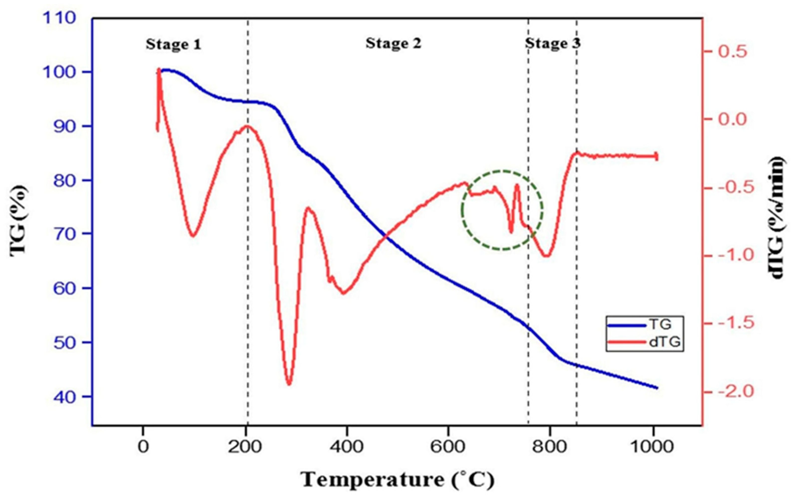
Figure 1. TG/DTG curves of the as-synthesised NiO–BCZY powder.
Processes 11 01902 g001
Figure 2. Differential scanning calorimetry (DSC) plot of as-synthesised NiO–BCZY powder.
Processes 11 01902 g002
Figure 3. XRD pattern of NiO–BCZY powder calcined at 1100 °C.
Processes 11 01902 g003
Figure 4. Morphology of the NiO–BCZY anode composite powder after calcining at 1100 °C. Red dotted circles represent particle agglomeration.
Processes 11 01902 g004
Figure 5. EDX spectrum of the NiO–BCZY powder after calcining at 1100 °C.
Processes 11 01902 g005
Figure 6. Elemental mapping of NiO–BCZY powder after calcining at 1100 °C.
Processes 11 01902 g006
Figure 7. Particle size distribution of NiO–BCZY calcined powder.
Processes 11 01902 g007
Figure 8. FESEM images of (ac) surface and (df) cross section of reduced Ni–BCZY anode films after sintering at (a,d) 1200 °C, (b,e) 1300 °C and (c,f) 1400 °C for 3 h.
Processes 11 01902 g008
Figure 9. DC electrical conductivity of Ni–BCZY anode sintered at different temperatures.
Processes 11 01902 g009
Figure 10. Electrochemical impedance spectra and fitted results of the Ni–BCZY/BCY/Ni–BCZY symmetrical cell operated at 800 °C under a humidified gas mixture of H2 (10%) and N2 (90%) sintered at 1200 °C, 1300 °C and 1400 °C.
Processes 11 01902 g010
Figure 11. Equivalent electrical circuit.
Processes 11 01902 g011
Table 1. List of ingredients used in the fabrication of the anode screen–printing ink.
IngredientsName of IngredientsWeight (wt%)
SolidNiO–BCZY (prepared by sol–gel)70.0
SolventTerpineol27.2
BinderEthyl cellulose N7 grade1.4
DispersantHypermer KD91.4
Table 2. Values of lattice parameter (a) and density (ρ) of NiO and BCZY.
Materiala (Å)ρ (g cm−3)
NiO (this work)4.17686.63
NiO (JCPDS card 010780643)4.17606.81
BCZY (this work)4.33156.12
Ba(Ce,Zr)O3 (JCPDS card 010892485)4.34366.30
Table 3. Elemental composition of NiO–BCZY powder after calcining at 1100 °C.
ElementMass Percentage from EDX (wt%)Calculated Mass Percentage (wt%)Nominal Mole RatioCalculated Mole Ratio
Ni21.4018.731.001.00
Ba35.6040.111.001.00
Ce19.1022.100.540.60
Zr6.209.590.360.30
Y2.102.600.100.10
Table 4. Thickness and porosity of the reduced Ni–BCZY anode films sintered at different temperatures.
Sintering Temperature (°C)Film Thickness (µm)Porosity (%)
120028.95 ± 2.3433.98 ± 0.52
130027.29 ± 2.5329.47 ± 0.62
140026.18 ± 1.2026.93 ± 0.65
Table 5. Capacitance, resistance, characteristic frequency and area-specific resistance for the equivalent circuit of the cells.
Sintering Temperature (°C)Resistance 1, R1
(Ω cm2)
Resistance 2, R2
(Ω cm2)
Area Specific Resistance ASR,
(Ω cm2)
Capacitance, C (F)Frequency, fmax (Hz)
CPE1CPE2fCPE1fCPE2
120055.82732.66816.3349.00 × 10−87.92 × 10−43.17 × 1046.15
130019.97810.6925.3462.25 × 10−74.12 × 10−33.53 × 1043.61
14001.9820.3481.1651.62 × 10−53.78 × 10−24.97 × 10312.1
Table 6. List of studies on PCFC anode materials.
AnodePowder Preparation MethodAnode Preparation TechniqueElectrolyteSintering ConditionReducing ConditionActivation Energy (eV)ASR (Ω cm2)Reference
1 Ni–BCZYSol–gelScreen–printing2 BCY1400 (3 h)Humidified (3%H2O) 10%H2–90%N2, 800 °C (2 h) _1.165 (800 °C, 10%H2–90%N2, 3%H2O)In this work
3 Ni–BCYBall millingBrush–Painting4 BCY1200 (2 h)Wet H2, 900 °C (1 h)0.261.06–0.39 (600–900 °C, wet H2)[10]
5 Ni–BCGCBall millingBrush–Painting6 BCGC1200 (2 h)Wet H2, 900 °C (1 h)0.460.7–0.15 (600–900 °C, wet H2)[10]
7 Ni–BZCYYbBall milling Dry pressing8 BZCYYb-ZnO1300 (4 h)5%H2 in N2, 700 (2 h)0.520.0245 (600 °C, pure H2)[48]
9 Ni–BZCYYbBall millingDry pressing10 BZCYYb1450 (5 h)Humidified H2 (~3% H2O)0.820.31 (550 °C), 0.23 (600 °C), 0.19 (650 °C) (~3% H2O)[49]
11 Ni–BZCYSol–gelDry pressing12 BZCY1400 (5 h)___[11]
13 Ni–BZCYYbBall millingDry pressing14 BZCYYb1450 (10 h)10% H2–90%N20.850.15 (600 °C)[50]
15 Ni–BZCYYbBall millingExtrusion16 BZCYYb900 (1 h)
1350 (3 h)
950 (1 h)
Humidified H2 (3%H2O)1.18_[51]
17 Ni–BSCZYBall millingTape casting18 BSCIY1450 (4 h)95%Ar–5%H2, 800 °C (4 h)0.74_[52]
Notes: 1 Ni–BaCe0.54Zr0.36Y0.1O3-δ; 2 BaCe0.9Y0.1O3-δ; 3 Ni–BaCe0.8Y0.2O3-δ; 4 BaCe0.8Y0.2O3-δ; 5 Ni–BaCe0.89Gd0.1Cu0.01O3-δ; 6 BaCe0.89Gd0.1Cu0.01O3-δ; 7 Ni–BaZr0.1Ce0.7Y0.1Yb0.1O3-δ; 8 BaZr0.1Ce0.7Y0.1Yb0.1O3-δ; 9 Ni–BaZr0.1Ce0.7Y0.1Yb0.1O3-δ; 10 BaZr0.1Ce0.7Y0.1Yb0.1O3-δ; 11 Ni–BaZr0.3Ce0.5Y0.2O3-δ; 12 BaZr0.3Ce0.5Y0.2O3-δ; 13 Ni–Ba(Zr0.1Ce0.7Y0.1Yb0.1)0.95O3-δ; 14 Ba(Zr0.1Ce0.7Y0.1Yb0.1)0.95O3-δ; 15 Ni–BaZr0.1Ce0.7Y0.1Yb0.1O3-δ; 16 BaZr0.1Ce0.7Y0.1Yb0.1O3-δ; 17 Ni–Ba0.8Sr0.2Ce0.6Zr0.2Y0.2O3-δ; 18 Ba0.8Sr0.2Ce0.6Zr0.2Y0.2O3-δ.
Disclaimer/Publisher’s Note: The statements, opinions and data contained in all publications are solely those of the individual author(s) and contributor(s) and not of MDPI and/or the editor(s). MDPI and/or the editor(s) disclaim responsibility for any injury to people or property resulting from any ideas, methods, instructions or products referred to in the content.