Abstract
Conglomerate reservoirs are usually formed in sag slope belts, which have the characteristics of near-source rapid deposition, rapid sedimentary facies change, and distinct reservoir heterogeneity. Therefore, it is difficult to carry out treatments of stimulation because of insufficient understanding of the propagation mechanism of the unique “gravel-bypassing” and “gravel-penetrating” characteristics of fracture morphologies in Mahu conglomerate reservoirs. In order to study the law of hydraulic fracture propagation in conglomerate reservoirs, based on Brazilian splitting test results for conglomerates with different gravel particle sizes and different cementation degrees, true tri-axial fracturing experiments conducted in the laboratory were performed to conduct experimental research on natural conglomerate outcrops and analyze the effects of gravel size, fracturing fluid viscosity, and pumping rate on hydraulic fracture propagation morphology. The results show that: (1) the gravel cementation strength of fracture pressure is higher and the pressure drops preferably after fracturing. The fracture is more inclined to “pass through the gravel” to propagate in large-particle-size gravel. The poor gravel cementation of fracture pressure is relatively low-level and the pressure after fracture drops slightly, and fractures tend to occur at the margin of gravel; (2) using slick water for fracturing tends to initiate and propagate fractures at multiple points on the wellbore, which is conducive to the formation of complex fracture networks and the improvement of volume stimulation effects. Guanidine-gum fracturing has a higher fracture-forming efficiency and higher net pressure; and (3) a low pumping rate will increase the interaction degree between fractures and gravel, and gravels will cause a change in fracture roughness, resulting in small local fracture widths.
1. Introduction
As the demand for unconventional resources gradually increases [1], unconventional oil and gas, including shale oil and gas, are experiencing rapid growth [2]. Conglomerate reservoirs represent a typical kind of unconventional reservoir [3]. The Mahu Oilfield in the Junggar Basin of China, with abundant reserves up to 1 billion t [4], is a super-large compact glutenite oilfield. However, the unique structure of the conglomerate matrix leads to significant differences in percolation between this type of rock and ordinary rock [5]. Due to the influence of gravel, it is easy to observe fracture distortion and multiple propagation of fractures during reservoir stimulation of fracturing [6], and, given that the great depth of glutenite reservoirs is generally more than 3000 m, as well as the low porosity and permeability, it is difficult to stimulate the reservoirs [7,8]. Therefore, it is of great significance to clarify the propagation law of artificial fractures in glutenite for reservoir stimulation. In view of the glutenite reservoir in Ma 48 Lake sag, a series of studies have been conducted and some patterns have been determined. Meng Qingmin et al. [9] used the true tri-axial simulation fracturing test system to study the influence of gravel particle size, horizontal stress difference, and other factors on the shape of fracture propagation, as well as pressure curves, by monitoring the propagation of fractures in an artificial glutenite core during a real physical process. Liu Xiangjun et al. [10] carried out studies on rock mechanical properties and the fracture propagation mechanism for certain glutenite reservoirs with different lithologies. Liu [11] used laboratory physical experiments and numerical simulations to study the spatial spreading morphology of three-dimensional fracture networks under the combined effect of horizontal stress ratio and material inhomogeneity, and revealed the fracture initiation and extension mechanism of hydraulic fracturing in sand and gravel rocks. Wang Hao [12] conducted multiple groups of physical experiments on artificial glutenite specimens in laboratory conditions to study the influence of different gravels in glutenite on fracture extension. Ma et al. [13] carried out a detailed study on the influence of gravel size, horizontal stress difference, fracturing fluid viscosity, and pumping rate on fracture propagation pattern, fracture width, and injection pressure through the true tri-axial hydraulic fracturing test. It is considered that four types of interaction between hydraulic fractures and gravel can be determined: fracture suspension, gravel penetration, gravel bypass, and gravel attraction. The research mentioned above mainly focused on artificial glutenite specimens, which are different from natural glutenite in terms of mineral composition and mechanical properties. Thus, research on the fracture propagation law of natural glutenite reservoirs need to be further conducted. In this paper, the glutenite reservoir in the Mahu sag was taken as the research object, and a Brazil fracturing test was conducted to measure the tensile strengths of conglomerate specimens with different gravel particle sizes and cementation degrees [14]. Then, a fracture propagation simulation test of natural glutenite outcrop samples was carried out using a small-scale true tri-axial hydraulic fracturing experimental system [15].
2. Methodology
2.1. Rock Mechanical Parameters Test
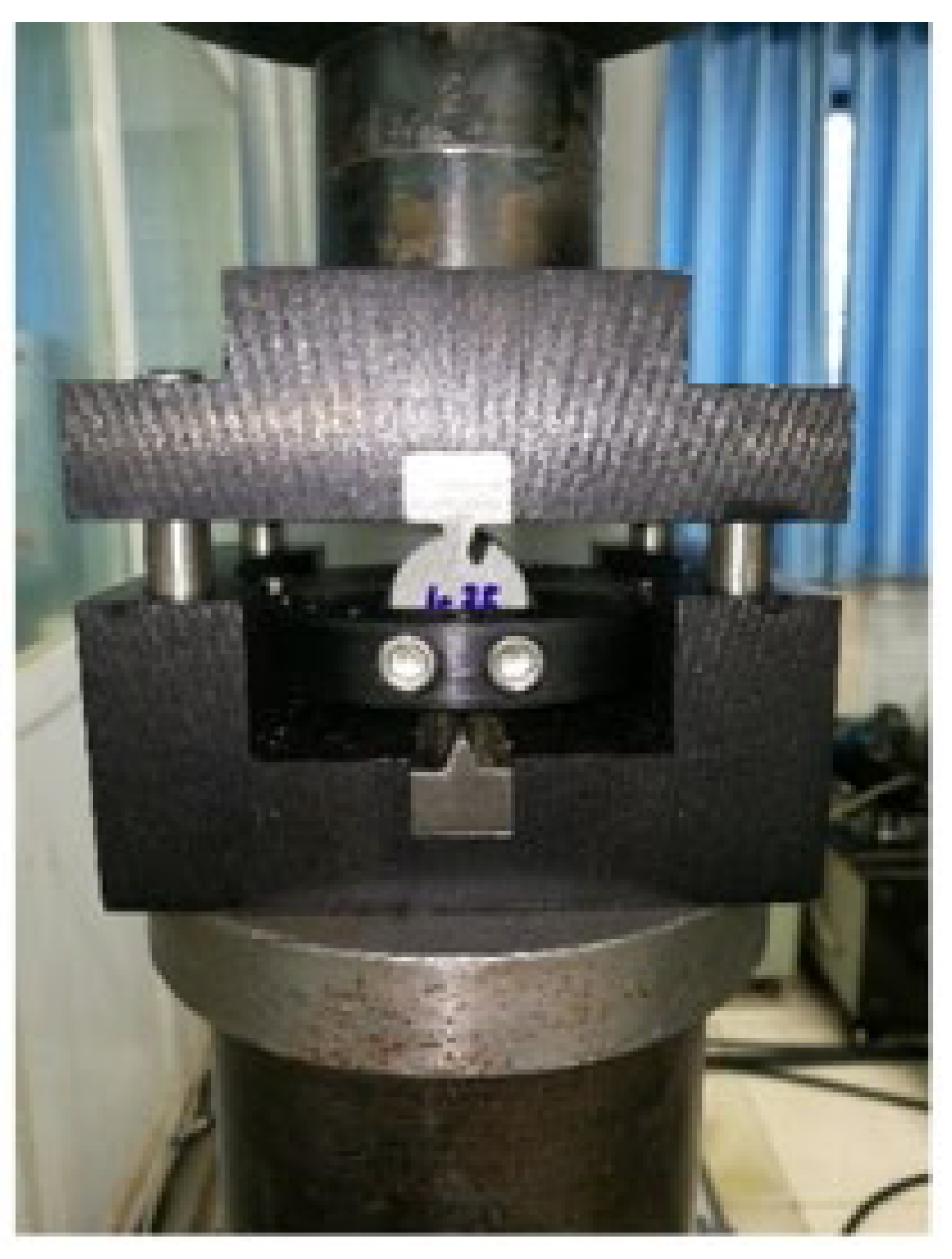
Hydraulic fracture propagation is closely related to the tensile strength of rock samples [16]. In order to study the tensile strengths of gravels with different cementation strengths, a Brazil splitting test [17,18,19] was carried out using a tensile strength testing device. The rock samples of the Upper Wuerhe Formation and the Lower Wuerhe Formation of Mahu used in the experiment were drilled to prepare cylindrical samples with a size of 25 mm× 13 mm. Each of the end faces were ground to make sure that the error for the parallel upper and lower end faces was within ±0.05 mm and that the surface flatness was controlled within 71 ± 0.03 mm [20]. The Brazilian splitting experiment equipment and the clamping state of conglomerate samples is shown in Figure 1.
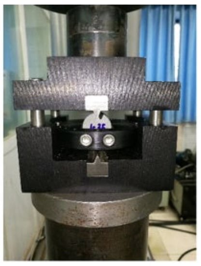
Figure 1.
The device used for the tensile strength test.
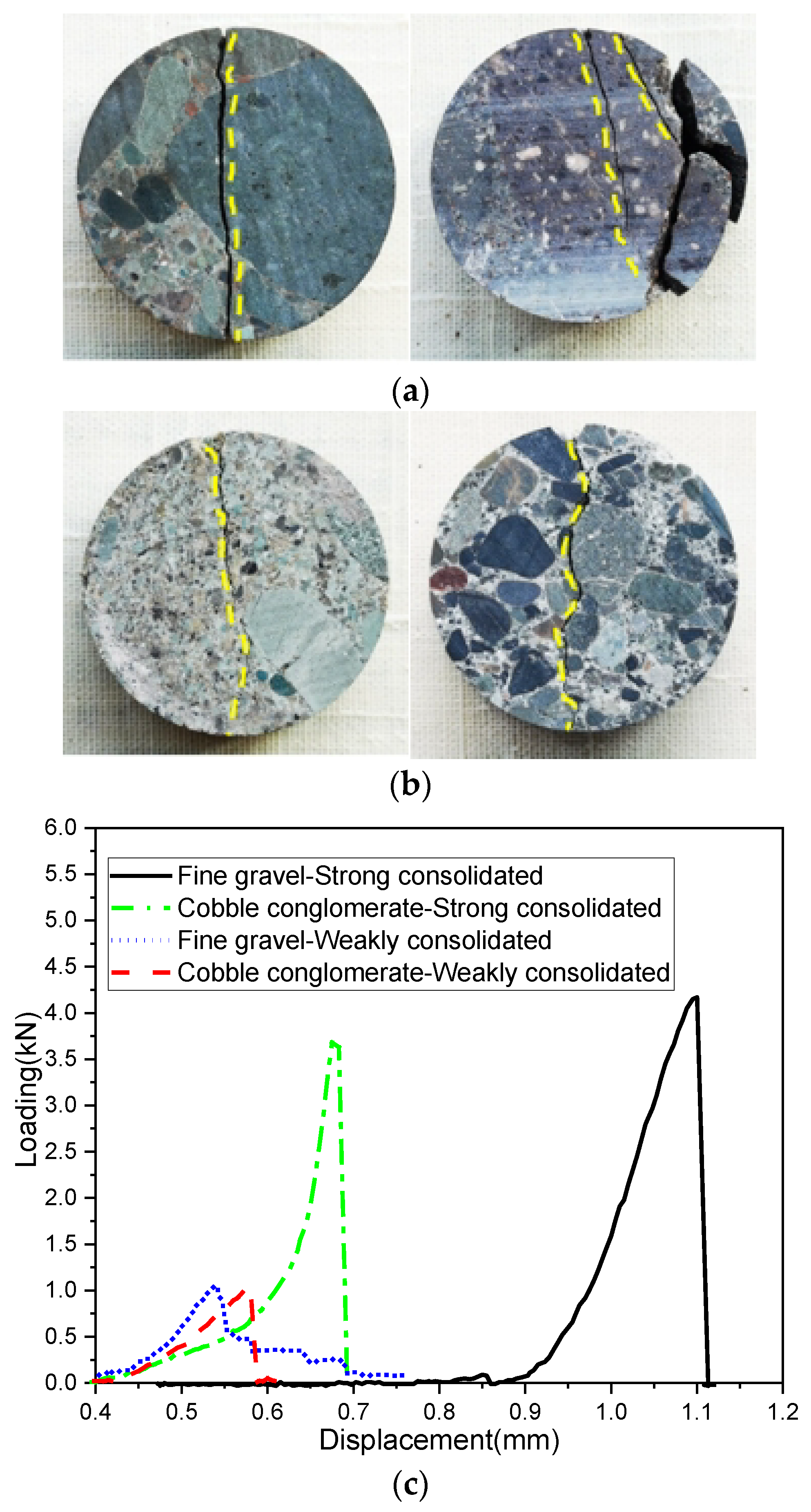
The Brazil splitting results for 4 samples are shown in Figure 2. The tensile strengths of the specimens “Fine Gravel- Strong consolidated” and “Cobble Conglomerate-Strong consolidated” were 8.09 MPa and 7.19 Mpa, respectively. Similarly, the tensile strengths of the specimens “Fine Gravel-Weakly consolidated” and “Cobble Conglomerate-Weakly consolidated” were 2.05 MPa and 2.30 MPa, respectively. The mechanical properties of the different types of conglomerates were significantly different, which was shown by the fact that the tensile strength decreased with the increase in gravel size, which means that the fracture was more likely to pass through gravel at a large grain size and more likely to pass around gravel at a small gravel size. However, regarding the specimens of fine gravel and loose cemented glutenite of the Upper Wuerhe Formation with poor cementation, the fractures of large and small gravels easily propagated around the gravel due to the significant difference between the mechanical properties of the gravel and the matrix, resulting in the inclination of fractures to propagate in the matrix and, by contrast, the rareness of fractures “gravel-penetrating”.
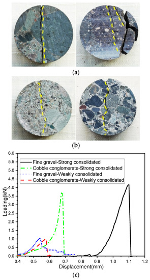
Figure 2.
The results of the Brazilian tensile strength test. (a) Sandy conglomerate rock with medium gravels. (b) Sandy conglomerate rock with fine gravels. (c) The tensile strength curves.
2.2. Rock Sources
The experimental specimens in this study were collected from the Wuerhe Formation in the Mahu sag, Junggar Basin. The lithology could mainly be interpreted as grain-supported conglomerate [21,22,23,24,25], given the particle sizes of the fine and medium gravels. The diameter of the gravel was generally 5–20 mm, with certain exceptions having dimensions of up to 28 mm × 40 mm, which lead to poor sorting, and showing equiaxed or long strip figures.
2.3. Experimental Equipment and Specimen Preparation
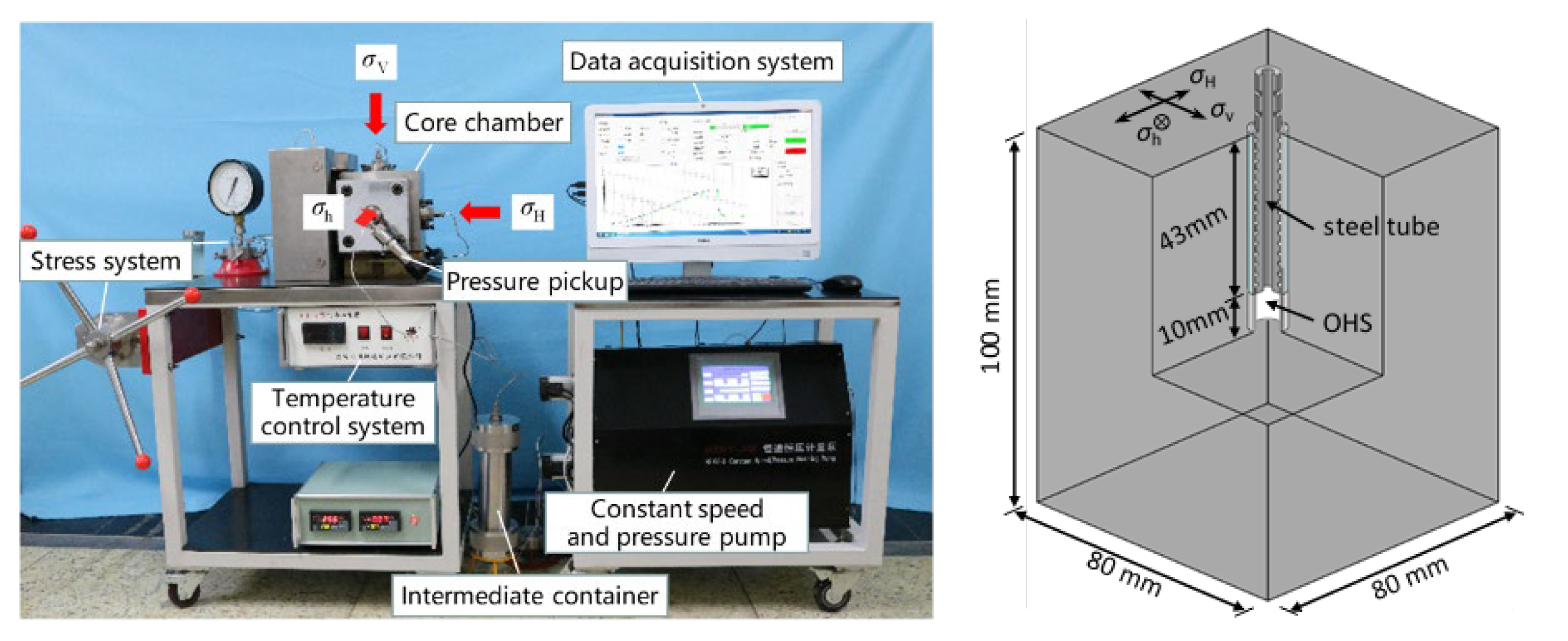
The hydraulic fracture propagation simulation test was carried out to investigate the propagation law in glutenite reservoirs using a small-scale true tri-axial hydraulic fracturing device [26,27] consisting of a hydraulic loading device, a pressurizing chamber, a pressure monitoring device, a piston container, a constant-speed constant-pressure metering pump, data-acquisition equipment, and so on. The maximum levels that the system could withstand was as follows: the confining pressure of the system was 23 MPa, the maximum pump pressure was 60 MPa, the maximum injection volume was 2000 mL, and the maximum pumping rate was 20 mL/min. The arrangement is shown in Figure 1. The test rock sample was a cuboid of 80 × 80 × 100 mm3, in which an open hole with a diameter of 16 mm and a depth of 53 mm was drilled at the center of one side. The steel pipe (the wellbore) with an outer diameter of 15 mm, an inner diameter of 10 mm, and a length of 43 mm was consolidated in the blind hole using high-strength epoxy resin adhesive, and a 10 mm open-hole section was reserved at the bottom. The small-scale true tri-axial hydraulic fracturing device and cementing treatment of specimens was shown in Figure 3.

Figure 3.
The small-scale true tri-axial hydraulic fracturing device and specimens subjected to cementing treatment.
2.4. Experimental Methodology
In order to simulate the tri-axial stress condition underground and the completion of a horizontal well, a true tri-axial fracturing simulation experimental system was adopted, and the horizontal minimum principal stress (σh), the horizontal maximum principal stress (σH), and the vertical stress were respectively applied in the X-, Y- and Z-directions. The direction of the wellbore was consistent with that of the minimum horizontal principal stress (X-axis). The prepared core was placed in the core chamber, and a pipeline was connected to make the core under the boosting pressure. Based on different operation parameters and rock types, six core samples were selected and divided into three groups to conduct the experiment. Then, fracturing fluid was injected into the rock sample for fracturing. Owing to the small size of the sample, the fracture extended quickly and easily reached to the boundary. In order to better observe the fracture shape, a tracer was added to the fracturing fluid to observe the fracture shape of the specimen on the surface using color-detection reagent after the treatment. The change in injection pressure was recorded by the data-collecting instrument to determine the fracture pressure; when the pressure reached the fracture pressure, the reading began to drop. After the continuous injection of fracturing fluid for 1 min, the specimen was taken out of the chamber and cut open to observe the fracture morphology. The experimental scheme design is shown in Table 1.

Table 1.
The scheme of the experiment.
3. Results and Discussion
The elastic modulus of the gravel in the Mahu sag can be 44.5 times that of the matrix, and the hardness of the gravel can even reach 179.3 times that of the matrix [28], which reflects the strong heterogeneity of the Mahu area. Based on the results of the true tri-axial hydraulic fracturing experiment, this paper analyzes the morphological characteristics of the propagation of hydraulic fractures and determines the expansion propagation of artificial fractures in the conglomerate reservoirs.
3.1. Description of the Experimental Results
3.1.1. Effect of Gravel Size on Fracture Morphology
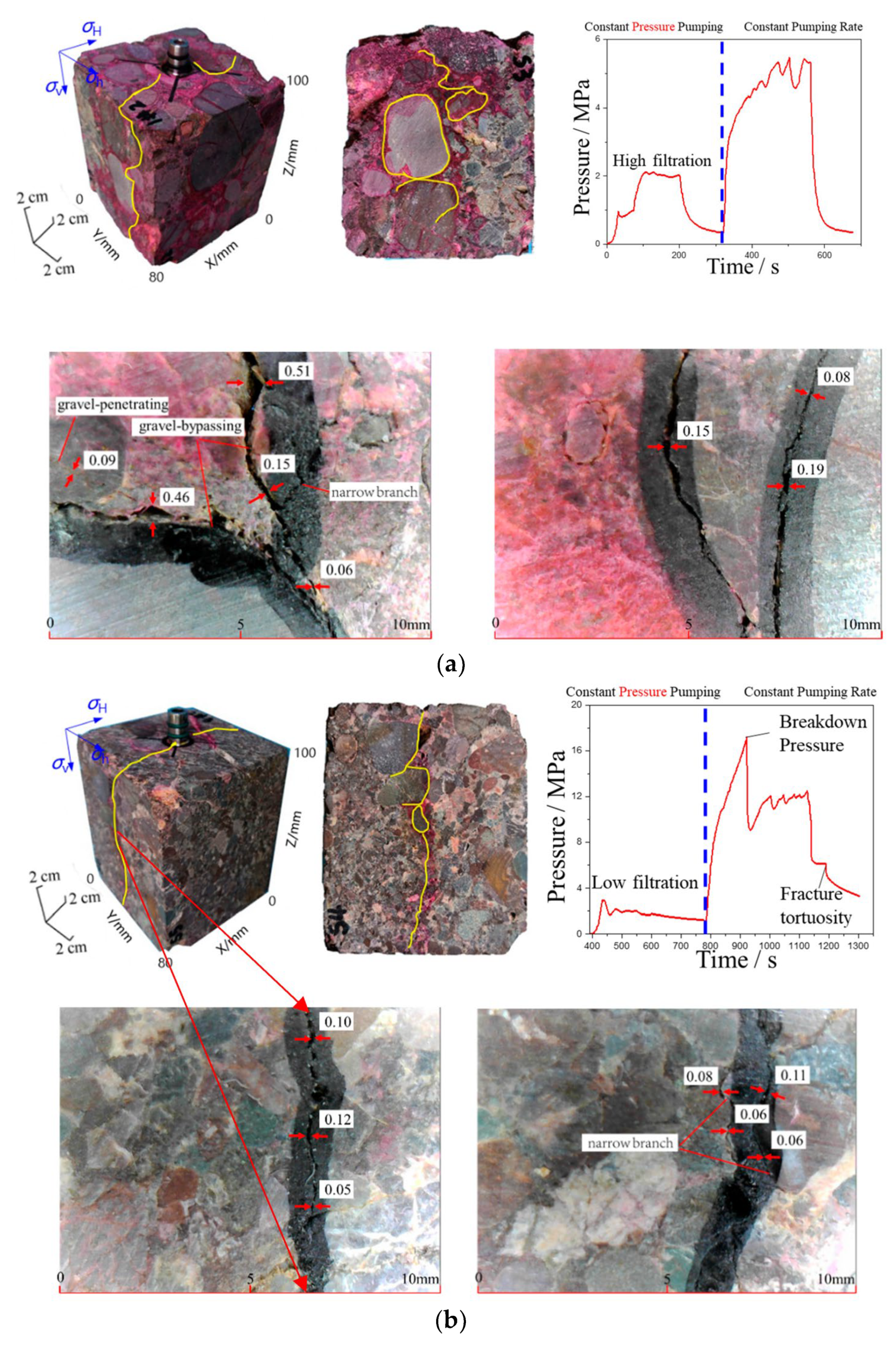
The gravel sizes and distributions of the #1 and #6 rock samples were significantly different. The gravel of the #6 rock sample had a preferable sorting ability and was generally smaller in size, while the sorting of the #1 rock sample was relatively poor. During the test, the same tri-axial stress was applied to the two specimens and guanidine-gum fracturing fluid with a viscosity of 50 mPa·s was pumped at a set rate of 50 mL/min. The shapes of the fracture morphologies of the rock samples after fracturing are shown in Figure 4a,b. The filtration loss of the fine gravel (#6) sample was relatively inconspicuous. After the constant pressure pumping phase, the wellbore pressure increased drastically and reached 17.23 MPa, which proved a high fracture pressure for fracturing. The morphological characteristics of the fracture showed that the fracture occurred at the open-hole section in the middle of the conglomerate. When the fracture propagated upward, it tended to pass around the gravel to form a branch fracture, which was propagated along the gravel on both sides, but the fracture on the left side was arrested within a certain distance, while the fracture on the right side passed around the gravel and formed a multi-branch fracture when it propagated to the upper large gravel. Similarly, the fracture of the left branch stopped propagating for a certain distance. The reason for this phenomenon was that the matrix and the small-grain-size gravel with good sorting properties were well cemented on the left side of the large-grain-size gravel, while the right side was weakly bonded with the matrix and the larger-grain-size gravels, leading to a poor cementation which was beneficial for the fracture propagation with respect to forming a complex fracture network. When the fracture propagated beneath the rock, it often passed through the gravel and reached the boundary. The coarse gravel (#1) rock sample had strong filtration, resulting in the inferior pressure of formation breakdown; also, the fracture propagated along the gravel interface.
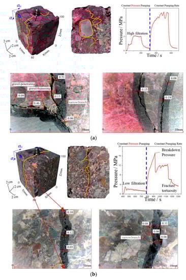
Figure 4.
The fracture morphologies of the specimens with gravels of different diameters. (a) The fracture morphology of the specimen with a large gravel size and the head pressure curve. (b) The fracture morphology of the specimen with a small gravel size and the head pressure curve.
The width of fractures generated by the hydraulic fracturing of coarse gravel samples varied greatly, with a coefficient of variation of up to 0.867. In addition, the crack width of the coarse gravel samples was generally higher than that of the fine gravel samples. Hydro-fracture treatment curves for the specimens and microscopic width scanning for different gravel particle sizes are shown in Figure 4.
3.1.2. Effect of Fracturing Fluid Viscosity on Fracture Propagation
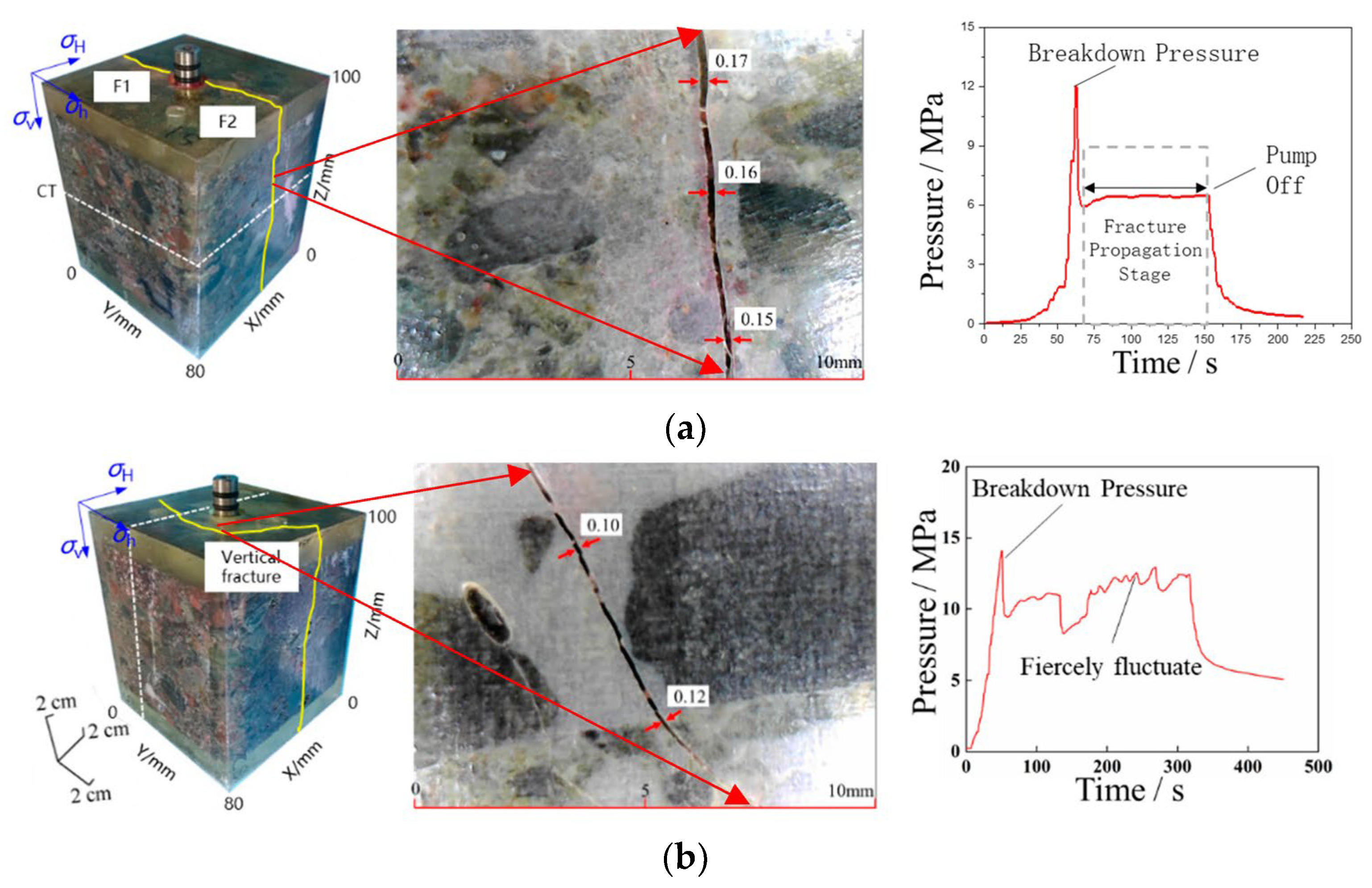
During the experiment, the horizontal stress difference under loading was 12 MPa; slick water (#2) and guanidine gum (#5) with μ = 1 mPa·s and μ = 50 mPa·s, respectively, were used as the fracturing fluids; and the constant rate of injection was set to 150 mL/min. The morphologies of the fractures and the fracturing curves are shown in Figure 5.
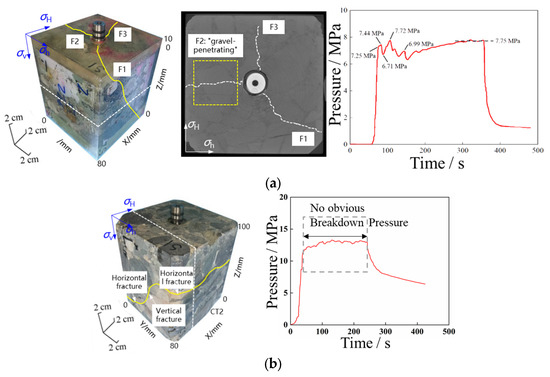
Figure 5.
The fracture morphologies of the specimens treated with fracturing fluids with different viscosities and the head pressure curves. (a) The slick-water fracturing fluid. (b) The guanidine-gum fracturing fluid.
The slick-water fracturing fluid had more filtration loss, which was difficult to break quickly, and the fracturing fluid tended to fill the pores near the wellbore before reaching the fracture pressure, leading to multi-point fractures at the wellbore, while the guanidine-gum fracturing fluid was liable to form a single-wing fracture in the direction of the maximum horizontal principal stress. Regarding the geometries of the hydraulic fractures in the grain-supported medium conglomerate, they were mainly two-wing fractures (fractures 1 and 2) in the direction of the maximum horizontal principal stress, and there was a single-wing fracture (fracture 3) in the direction of the minimum horizontal principal stress. Fracture 1 extended along the gravel edge to the boundary, while fracture 2 directly passed through the large-size conglomerate to the boundary. Only fracture 3 passed further through the gravels several times after the fracture initiation at the wellbore and stopped at the upper part of the large-size conglomerate before reaching the boundary.
The filtration of the guanidine-gum fracturing fluid was relatively low, and that is the reason why the bottom-hole pressure phase increased rapidly compared with that of sample #2. An inflection point appeared after the pressure reached 11.4 MPa, which means that the core had micro-mechanical damage inside, but there was no distinct observation of fracture pressure. With the fracturing-fluid injection, the bottom-hole pressure was basically stable at around 13 MPa, then vertical fractures were formed near the wellbore. The fractures which propagated upward around the gravel formed horizontal branch fractures: the left fractures turned to and passed through the gravel to the boundary, while the right fractures passed around the gravel several times. The vertical fracture near the wellbore propagated downward, passing through the gravel edge and formed a horizontal branch fracture when it encountered the boulder. The left fracture extended to the boundary along the weak cementation surface between the gravel and the matrix. The right fracture firstly passed through the gravel, then changed direction under the horizontal principal stress. After extending in the horizontal direction for a certain distance and encountering gravel, it formed a fracture that penetrated the gravel and reached the boundary. With respect to the pressure curve, the fracturing efficiency with guanidine gum was higher, as well as the net pressure.
3.1.3. Effect of Pumping Rate on Fracture Propagation
Pumping rate was one of the important factors that affected the morphology of the hydraulic fractures. During the experiment, 12 Mpa of horizontal stress difference was applied to fracture samples #3 and #4, and slick water with a viscosity of 1 mPa·s was used at two constant injection rates, 50 mL/min and 200 mL/min, respectively. The fracture shapes and fracturing curves after the fracturing of specimens #3 and #4 are shown in Figure 6.

Figure 6.
The fracture morphologies of the specimens treated with different pumping rates and the head pressure curves. (a) Q = 200 mL/min. (b) Q = 50 mL/min.
Under the condition of a low pumping rate (Q = 50 mL/min), the fracture initiated from the wellbore once the pressure reached the fracture point—20.3 MPa. The fracture propagation was dominated by gravel mainly passing along the edge of the gravel. It was noticed that the path of propagation deviated from the direction of the horizontal maximum principal stress and demonstrated a tortuous fracture shape. The extension process of the fracture interacted with the gravel frequently, resulting in a violent fluctuation in pressure in the process of fracture propagation. Under the condition of a higher rate (Q = 200 mL/min), the fracture propagation was dominated by the in-situ stress, such that the fracture mainly propagated in the direction of the horizontal maximum principal stress. In this circumstance, the fracture might have propagated, ignoring the block of small-diameter gravel in the propagation path; after the peak value of the fracture curve fell, the fracture extension pressure was stable without obvious fluctuation.
The fracture widths of the conglomerate samples with different pumping rates showed no significant changes, but the average fracture width of the conglomerate samples with a high pumping rate was slightly larger than that of the conglomerate samples with low displacement. Hydro-fracture construction curves for the specimens and microscopic width scanning with different pumping rates are shown in Figure 6.
3.2. Analysis of the Experimental Results
The differences between the fracture propagation pressure curves of the conglomerates reflect the complex interaction between the gravel and the hydraulic fractures. In view of the slick-water fracturing, three fracturing modes can be summarized based on the tendency of the change in over-peak pressure (the pressure point where the specimen begins to develop macroscopic fractures) as well as the change in extension pressure.
3.2.1. Mode 1: Over-Peak Pressure Drop—Propagation Pressure Flat
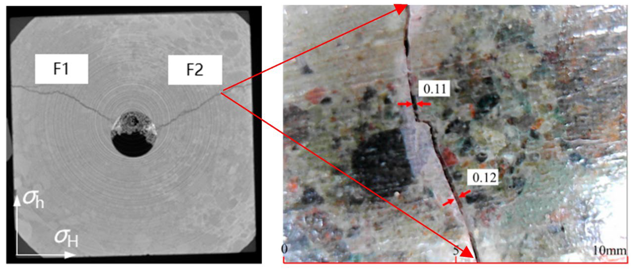
This pattern of pressure response generally occurred when the conglomerate was well cemented and the pumping rate was at a high level. In the process of the pumping stage, obvious pressure fluctuations in the curve could be seen when the injection pressure reached 2 MPa and 8.2 MPa due to the formation of micro-fractures prior to macro-fractures in the sample. When the pressure reached 20.3 MPa, macroscopic fractures developed, resulting in a sharp drop in pressure down to 5.9 MPa—a decrease of 70.94%. The rapid release of pressure meant that the fracture showed an intensity trend of extension. As shown in Figure 7, the fracture on the left wing propagated continuously with the penetrating gravel of the fracture morphology. When it approached the boundary of the specimen and encountered the gravel, the fracture was deflected. After extending along the gravel boundary for a short distance, it was deflected again and passed through the gravel and tended to form a narrow branch fracture induced by the gravel. The fracture on the right side started from the wellbore and extended symmetrically, with the left-wing fracture wellbore as the central axis. The final shape of the hydraulic fracture was primarily a vertical major fracture approximately parallel to the direction of the maximum horizontal principal stress, yet with obvious distortion and bifurcation.

Figure 7.
The pressure curve for mode 1 corresponding to the fracture morphology determined by CT scanning.
It was observed in the pressure curve that the fracture had a minor increase after a sharp drop in pressure, and then the pressure smoothened, with a slight fluctuation that was, after the conglomerate broke, due to the influence of the gravel with a larger particle size near the wellbore. A tortuous narrow fracture thus formed, and the pressure dropped sharply to 6.1 MPa. Then, the bottom-hole pressure raised to 10.2 MPa due to the reopening of the tortuous narrow fracture. During the propagation, the bottom-hole pressure interacted with the gravel but the pressure curve remained stable at about 9.5 Mpa overall, with slight fluctuations. The pressure fluctuation specifically manifested the interference of gravel in fracture propagation. The pressure fluctuations of the #4 (frequent and violent fluctuations) and #3 specimens (slight fluctuations) were due to the closing and opening of tortuous narrow fractures and the process of the continuous establishment of force balance in tortuous narrow fractures. However, it was noticed that the difference in fluctuation degree indicated that the interference of gravel in fracture propagation could be significantly reduced by injecting at a higher pumping rate (#3 Q = 200 mL/min).
3.2.2. Mode 2: Over-Peak Pressure Decreased Slightly—Stable Extension Pressure
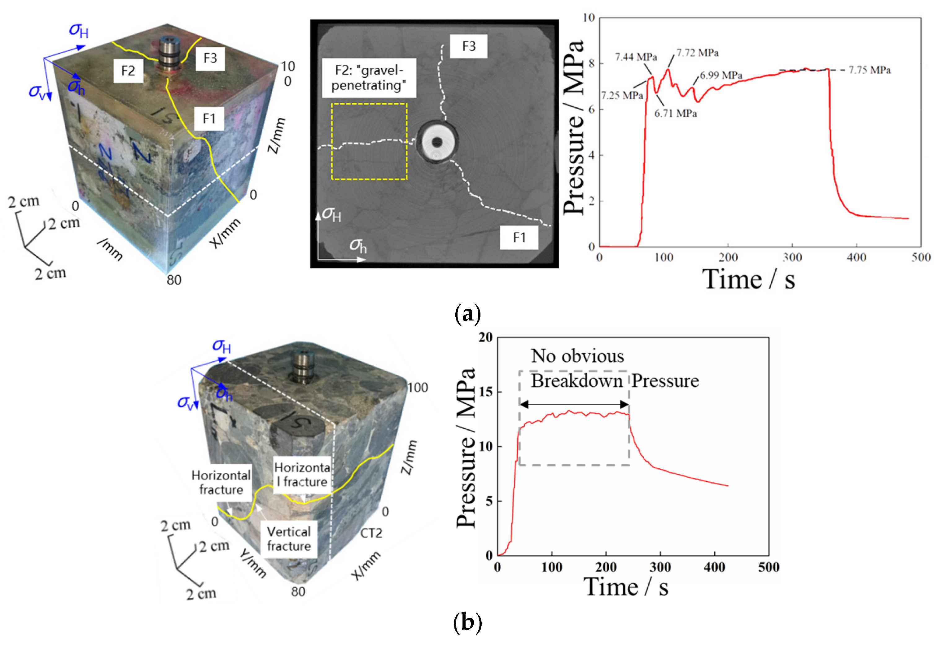
This type of pressure pattern usually occurred in medium–fine conglomerates with poor cementation. According to the pressure curve, the inflection point appeared when the pressure raised to 7.25 Mpa, which indicated that the near-wellbore zone had meso-damage at this time. When the pressure continuously increased to 7.44 MPa, the pressure dropped slightly to 6.71 MPa—a decrease of merely 9.8%. Both the initial fracture pressure and the pressure drop were smaller than for mode 1.
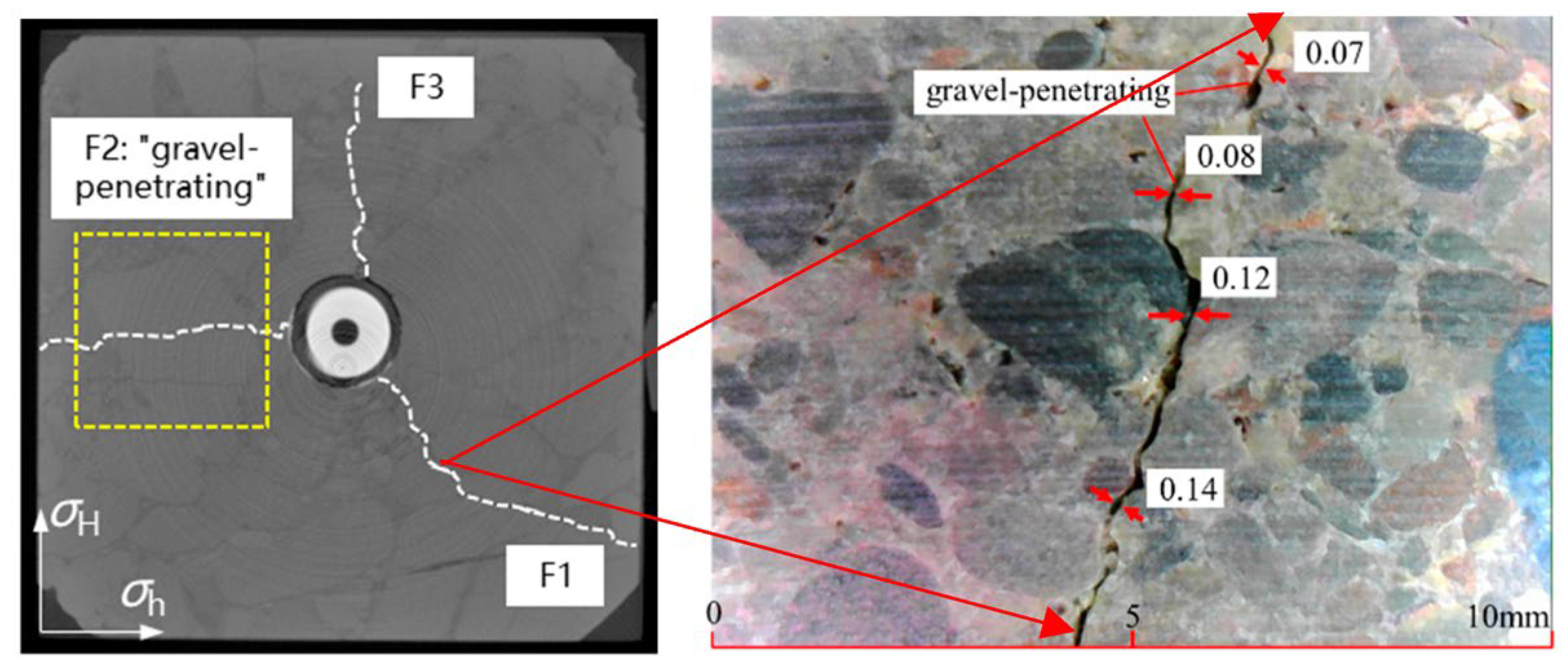
In combination with CT scanning, it was found that the initiation fracture was at the edge of the fine gravel, which indicated that the small pressure drop during the initial fracturing stage corresponded to the fracture of the cementation interface of the gravels. The fracture propagated at the edge of the fine gravel and frequently interacted with the gravel during the extension, as was reflected by the high frequency of pressure fluctuations in the curve, indicating that the subsequent pressure fluctuation corresponded to fracture propagation at the interface of the small-grain gravel cement around the well, which meant that multi-peak pressure was exerted at the beginning of the fracture propagation stage. This phenomenon was caused by the positive correlation between the fracture toughness of the gravel and the grain size [14]. After the fracture of the small-grain gravel around the well, the fracture tended to pass around the gravel with a more tortuous morphology, and the gravel had an influence on fracture roughness, resulting in decreases in local fracture width (the average width of the “gravel-penetrating” fractures was only the general width of the “gravel-bypassing” fractures). When fractures extended away from the wellbore and met gravel of larger grain size, fractures 2 and 3 passed through the gravel. This indicated that the fracture was more inclined to penetrate gravels which have larger grain sizes, and the pressure fluctuation range significantly reduced. The tortuosity of the fracture morphology was significantly reduced compared with the degree of that at the edge of the small-grain-size gravel around the well. After fracturing, the sample formed the near-well multi-branch “gravel-bypassing” fractures, which were narrow and tortuous in a radial direction. The pressure curve showed that the pressure raised slowly to 7.75 MPa at the propagation stage, which was roughly equivalent to the initial fracture pressure, indicating that the fluid flow resistance in the tortuous narrow fracture was relatively superior. However, the fracture initiation at the fine gravel increased the complexity of the fracture at the wellbore (compared with the fracture propagation of the #4 specimen), which was conducive to the formation of a complex fracture network and the improvement of volume stimulation. Compared with fracture 1 and fracture 2, the larger-size conglomerate at fracture 1 had a higher roundness to the extent that the fracture tended to expand around the gravel, while the gravel at fracture 2 had higher irregularity, so that it was liable to form “gravel-bypassing” fractures. The fracture morphology determined by CT and microscopic width scanning of Mode 2 was shown in Figure 8.
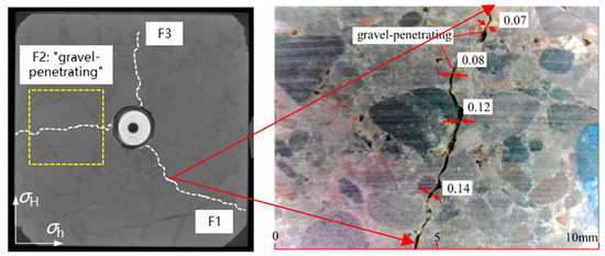
Figure 8.
The pressure curve for mode 2 corresponding to the fracture morphology determined by CT and microscopic width scanning.
3.2.3. Mode 3: No Significant Fracture Pressure
This type of pressure response generally occurred when the gravel was poorly cemented or broken off. It can be seen from Figure 3 that the inflection point occurred at 11.4 MPa after the wellbore pressure build-up, indicating that the gravel edge near the wellbore was damaged at a microscopic level, and the fluid flowed into the cemented interface to drive the fracture at the edge of the gravel, extending it further. Due to the poor cementation of the gravel, the opening at the edge, presented as a microscopic fracture without obvious macroscopic fracture pressure, could be observed. Meanwhile, the fractures formed were insufficiently open, with small widths.
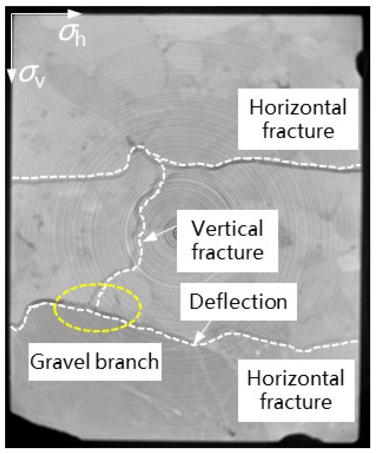
The major gravels in the specimen were cobble conglomerate, but the pressure did not increase rapidly during the extension stage, with a slight fluctuation up to 13.0 MPa. This was because the edge of the gravel in the cobble conglomerate had been partially detached (see Figure 9), and the narrow fractures near the wellbore were connected to these cracks caused by detached gravel to form a dominant channel, to which the fracture fluid had less resistance. The random distribution of gravel led to the uncertain distribution of fractures caused by detached gravel, and the detached fractures might have changed the propagating direction after connecting with fracturing fractures, increasing the complexity of the fracture morphology. After the detached fracture connected with the fracturing fracture, both the vertical and horizontal fractures formed a complex morphology, with the vertical and horizontal fractures orthogonal to each other. Meanwhile, it was noted that the lower fracture was deflected in the process of passing around the gravel and continued to propagate away from the gravel interface, which further increased the complexity and tortuosity of the fractures.

Figure 9.
The pressure curve of mode 3 corresponding to the fracture morphology determined by CT scanning.
4. Conclusions
The effects of gravel size, the viscosity of the fracturing fluid, and the pumping rate on fracture morphology and pumping pressure were studied in laboratory fracturing simulation tests on gravel-supported conglomerates. The following conclusions can be drawn:
(1) When the gravel was well cemented, the initial fracture pressure of the conglomerates was high but underwent a drastic drop after fracturing, and the fracture tended to penetrate the gravel fracture. When the gravel was characterized by poor cementation, the fracture pressure of the conglomerate was low, corresponding to a slight decrease in pressure after fracturing, and the fracture tended to extend at the gravel boundary. If broad-fracture penetrating gravel formed consecutively, the extensional pressure remained low with a smooth curve. If the wellbore zone was blocked by gravels of large size, then tortuous narrow cracks around the gravels or in the gravels formed, resulting in the increasing pressure of extension.
(2) With the increase in horizontal stress difference, the viscosity of the fracturing fluid and the cementation strength of gravel and the morphology of the fracture-tip area tended to change from a complex fracture network around gravels showing “multiple fractures near the wellbore, multiple branches when encountering gravel, and local gravel surrounding fracture” to a simple main fracture penetrating gravels with two wings, reflecting the transition from the “gravel leading rule” to the “stress leading rule”.
(3) The strong heterogeneity of the conglomerate led to a significant difference in the width of the hydraulic fractures. In the same sample, the average width of the “gravel-penetrating” fractures was only the general width of the “gravel-bypassing” fractures. The fracture widths of the coarse gravel samples varied greatly, with a coefficient of variation of up to 0.867, which was far higher than that for the granule conglomerate (0.402).
Author Contributions
Conceptualization, S.Z. and Y.Z. (Yushi Zou); methodology, Y.D.; validation, J.Q.; formal analysis, J.Z.; investigation, Y.Z. (Yue Zhu); resources, Y.Z. (Yue Zhu); data curation, Y.Z. (Yushi Zou); writing—original draft preparation, S.L.; writing—review and editing, Y.Z. (Yue Zhu); All authors have read and agreed to the published version of the manuscript.
Funding
This research received no external funding.
Data Availability Statement
Not applicable.
Conflicts of Interest
The authors declare no conflict of interest.
References
- Xiao, Z.; Chen, S.; Liao, J.; Li, Y.; Wang, P.; Ding, Z. Channel architecture element and its controls on hydrocarbon accumulation: A case study from Chang-8 member in Huaqing area, Ordos basin. Xinjiang Pet. Geol. 2018, 39, 524–529. [Google Scholar]
- Chen, X.; Zhi, D.; Wang, X. Typical Reservoirs in Oil and Gas Fields of Junggar Basin: The Southern Margin; Petroleum Industry Press: Beijing, China, 2018. [Google Scholar]
- Zou, C.-N.; Zhang, G.-Y.; Tao, S.-Z.; Hu, S.-Y.; Li, X.-D.; Li, J.-Z.; Dong, D.-Z.; Zhu, R.-K.; Yuan, X.-J.; Hou, L.-H.; et al. Geological features, major discoveries and unconventional petroleum geology in the global petroleum exploration. Pet. Explor. Dev. 2010, 37, 129–145. [Google Scholar]
- Yang, Y.-T. Evaluation of Petroleum Resources in Mahu Area, Junggar Basin. Guangzhou Chem. Ind. 2022, 50, 191–193+196. [Google Scholar]
- Song, J.-G.; Li, X.-S.; You, H.-Y.; Pan, H.; Wang, S.; Gu, K.-F.; Luo, G.-X.; Li, T. Pressure Analysis of Fractured Horizontal Wells Considering the Complex Modal Structure of Mahu Conglomerate Reservoir. Sci. Technol. Eng. 2022, 22, 8295–8303. [Google Scholar]
- Pan, Y.-T.; Liu, P.-Y.; Shi, S.-Z.; Wang, T.; Shen, Y.-H.; Ge, H.-K. Fracture Interference Law of Mahu Tight Conglomerate. Sci. Technol. Eng. 2022, 22, 10050–10058. [Google Scholar]
- Hu, X.; Zou, H.; Hu, Z. Reservoir characteristics and main controlling factors of glutenite reservoir in fan dalta glutenite: A case study of the Upper Urho Formation of Permian in the east slope of Dongdaohaizi Sag, Junggal Basin. J. Northeast. Pet. Univ. 2021, 45, 15–26+5–6. [Google Scholar]
- Wang, Y.; Zhao, X.; Tang, C.; Zhang, X.; Ma, C.; Yi, X.; Jing, Y. Study on Microscopic Pore Structure Classification for EOR of Low Permeability Conglomerate Reservoirs in Mahu Sag. Energies 2023, 16, 626. [Google Scholar] [CrossRef]
- Meng, Q.M.; Zhang, S.C.; Guo, X.M.; Chen, X.H.; Zhang, Y. A Primary lnvestigation on Propagation Mechanism for Hydraulic Fractures in Glutenite Formation. J. Oil Gas Technol. 2010, 32, 119–123. [Google Scholar]
- Liu, X.; Xiong, J.; Liang, L. Rock Mechanical Characteristics and Fracture Propagation Mechanism of Sandy Conglomerate Reservoirs in Baikouquan Formation of Mahu Sag. Xinjiang Pet. Geol. 2018, 39, 83–91. [Google Scholar]
- Liu, P.; Ju, Y.; Ranjith, P.G.; Zheng, Z.; Chen, J. Experimental investigation of the effects of heterogeneity and geostress difference on the 3D growth and distribution of hydrofracturing cracks in unconventional reservoir rocks. J. Nat. Gas Sci. Eng. 2016, 35, 541–554. [Google Scholar] [CrossRef]
- Wang, H. The Study of Hydraulic Fracture Propagation Influenced by Gravel in Sand-Gravel Reservoir. Master’s Thesis, China University of Petroleum, Beijing, China, 2011. [Google Scholar]
- Ma, X.F.; Zou, Y.S.; Li, N.; Chen, M.; Zhang, Y.; Liu, Z. Experimental study on the mechanism of hydraulic fracture growth in a glutenite reservoir. J. Struct. Geol. 2017, 97, 37–47. [Google Scholar] [CrossRef]
- Chen, J. The Influence of Tensile Strength Difference with Variable Gravel Sizes on the Hydraulic Fracture Propagation in the Conglomerate Reservoir. Geofluids 2022, 2022, 5290189. [Google Scholar] [CrossRef]
- Li, G.; Ai, T.; Yu, B.; Zhang, R.; Gao, M.Z.; Xu, X.L. Acoustic emission characteristics of different lithologies under Brazilian splitting. J. China Coal Soc. 2015, 40, 870–881. [Google Scholar] [CrossRef]
- Su, C.D.; Zhang, S.; Tang, X. Experimental research on deformation and strength characteristics in process of Brazilian split fatigue failure of sandstone. Chin. J. Rock Mech. Eng. 2013, 32, 41–48. [Google Scholar]
- Qin-Feng, D.U.; Shun, Y.U.E.; Gao-Fei, D.A.I. Comparative study on direct tension test and splitting test. Undergr. Space 2004, 24, 178–181. [Google Scholar]
- Gang, W.U.; Zhenyang, Z. Acoustic emission character of rock materials failure during various stress states. Chin. J. Geotech. Eng. 1998, 20, 82–85. [Google Scholar]
- Li, S.L.; Yin, X.; Wang, Y.; Tang, H. Studies of acoustic emission characteristics of uniaxial compressive rock failure. Chin. J. Rock Mech. Eng. 2004, 23, 2499–2503. [Google Scholar]
- Hou, P.; Gao, F.; Yang, Y.; Zhang, Z.Z.; Gao, Y.; Zhang, X.; Zhang, J. Effect of bedding plane direction on acoustic emission characteristics of shale in Brazilian tests. Rock Soil Mech. 2016, 37, 603–1612. [Google Scholar]
- Zhang, C.M.; Wang, X.L.; Zhu, R.; Qu, J.H.; Pan, J.; An, Z.Y. Litho⁃ facies classification of Baikouquan formation in Mahu sag, Junggar basin. Xinjiang Pet. Geol. 2016, 37, 606–614. [Google Scholar]
- Wang, X.; Li, W.; Dong, H.; Zhu, J.; Zhang, D.; Yin, S. Genetic classification of sandy conglomerate facies and sedimentary characteris⁃ tics of fan delta: A case study from Upper Wuerhe formation in District Wuba in northwestern margin of Junggar basin. Xinjiang Pet. Geol. 2017, 38, 537–543. [Google Scholar]
- Zhang, C.M.; Yin, T.J.; Tang, Y.; Guo, G.X.; Zhao, K.; Pan, J.; Chen, M.L. Advances in sedimentological reservoir research in Mahu sag and northwest margin of Junggar basin. J. Palaeogeogr. 2020, 22, 129–146. [Google Scholar]
- Zhang, C.; Song, X.; Wang, X.; Wang, X.; Zhao, K.; Shuang, Q.; Li, S. Origin and depositional characteristics of supported conglomerates. Pet. Explor. Dev. 2020, 47, 272–285. [Google Scholar] [CrossRef]
- Yu, X.; Qu, J.; Tan, C.; Lei, Z.; Xiaolu, L.I.; Zhaopu, G. Conglomerate Lithofacies and Origin Models of Fan Deltas of Baikouquan Formation in Mahu Sag, Junggar Basin. Xinjiang Pet. Geol. 2014, 35, 619–627. [Google Scholar]
- Li, S.; Ma, X.; Zhang, S.; Zou, Y.; Li, N.; Zhang, Z. Experimental investigation on the influence of CO2 brine rock interaction on tight sandstone properties and fracture propagation. Xinjiang Pet. Geol. 2019, 40, 312–318. [Google Scholar]
- Zou, Y.S.; Li, N.; Ma, X.; Zhang, S.; Li, S. Experimental study on the growth behavior of supercritical CO2-induced fractures in a layered tight sandstone formation. J. Nat. Gas Sci. Eng. 2018, 49, 145–156. [Google Scholar] [CrossRef]
- Li, N.; Zhang, S.; Ma, X.; Zou, Y.S.; Chen, M.; Li, S.H.; Zhang, Y.N. Experimental study on the propagation mechanism of hydraulic fracture in glutenite for mations. Chin. J. Rock Mech. Eng. 2017, 36, 2383–2392. [Google Scholar]
Disclaimer/Publisher’s Note: The statements, opinions and data contained in all publications are solely those of the individual author(s) and contributor(s) and not of MDPI and/or the editor(s). MDPI and/or the editor(s) disclaim responsibility for any injury to people or property resulting from any ideas, methods, instructions or products referred to in the content. |
© 2023 by the authors. Licensee MDPI, Basel, Switzerland. This article is an open access article distributed under the terms and conditions of the Creative Commons Attribution (CC BY) license (https://creativecommons.org/licenses/by/4.0/).