Article

Reaction–Diffusion Process for Hydrogels with a Tailored Layer Structure

1
School of Materials Science and Chemical Engineering, Harbin University of Science and Technology, Harbin 150040, China
2
Institute for Advanced Ceramics, State Key Laboratory of Urban Water Resource and Environment, Harbin Institute of Technology, Harbin 150001, China
3
Key Laboratory of Engineering Dielectrics and Its Application, Ministry of Education, Harbin University of Science and Technology, Harbin 150080, China
*
Author to whom correspondence should be addressed.
Processes 2023, 11(7), 1975; https://doi.org/10.3390/pr11071975
Submission received: 31 May 2023 / Revised: 26 June 2023 / Accepted: 28 June 2023 / Published: 30 June 2023
(This article belongs to the Topic Advances in Biomass Conversion)

Abstract

:
The architecture of hydrogel composites results in not only synergistic property enhancement but also superior functionality. The reaction–diffusion (RD) process is acommon phenomenon throughout nature which induced ordered structure on a length scale from microscopic to macroscopic. Different from commonly used inorganic salts or oppositely charged nanoparticles for the RD process, a modified RD process was used for layered chitosan hydrogel (L-CH) and layered magnetic chitosan hydrogel (L-MCH). During the modified RD process reported in this paper, the protonated chitosan (CS-NH3+) with iron ions (Fe3+ and Fe2+) was used as an inner-reactant and hydroxide ion (-OH) was used as an out-reactant. The protonated chitosan (CS-NH3+) not only played the role of an inner-reactant but also the reaction medium which controlled the diffusion behavior of the out-reactant (-OH). A series of ordered layers were constructed and the ordered layers were parallel with the longitudinal axis. The layer width of L-CH and L-MCH can be tailored by varying interval time T. The mean layer width of L-MCH increased from 50 ± 5.8 μm to 90 ± 6.4 μm when the interval time T increased from 2 min to 5 min. The tailored layer structure of L-CH and L-MCH obeyed the time law and spacing law, which declared that the L-CH and L-MCH were constructed via the reaction–diffusion process. We also show that the tailored layer structure endows hydrogel with enhanced mechanical properties, especially toughness. The yield strength of magnetic chitosan hydrogel was improved significantly (from 95.1 ± 7.6 kPa to 401.7 ± 12.1 kPa, improved by about 4 times) when 10 wt. % magnetite nanoparticles were involved. The enhancement of the mechanical propertieswas due to a physical crosslinking effect of magnetite nanoparticles on chitosan. For L-MCH, the probe displacement reached 28.93 ± 2.6 mm when the rupture occurred, which was as high as 284.7% compared with that of the non-layered hydrogel. The tailor-made hydrogels might be possible for application as a tough implantable scaffold.

1. Introduction

Hydrogels obtained from natural polymers have attracted increasing attention for the development of biomedical applications due to their inherent bioavailability, drug efficacy and tolerance, and reduced toxicity [1]. Many hydrogel systems have been investigated, such as collagen, gelatin, chitosan, agarose, and hyaluronic acid. The combination of hydrogel with functional nanoparticles endows the hydrogel composites with superior functionality which makes the hydrogel composites possible for applications in diverse fields, such as drug delivery [2], tissue engineering [3], catalysis [4], bio-sensing [5], and environmental remediation [6]. For example, magnetic nanoparticles were embedded within polyvinyl pyrrolidone hydrogels and the magnetic hydrogels can carry a therapeutic agent and release the agent upon heating [7].
In recent years, more and more attention has been focused on the architecture or structural design of hydrogel composites with distinctive properties [8]. Materials design overwhelmingly focuses on attractive interactions or electrostatic repulsion, such as hydrogels with negatively charged nanosheets embedded, where electrostatic repulsion between nanosheets endowed hydrogels with anisotropic mechanical properties [9]. The constructed hydrogel composites might result in not only synergistic properties, but also superior functionality. Several approaches have been proposed to construct hydrogel composites with an ordered structure, such as layer by layer [10], fluid flow alignment [11], 3D printing [12], magnetic field induced orientation [13], and reaction–diffusion process [14]. Sakr et al. fabricated layer-by-layer coating using chondroitin sulfate as a negatively charged polyelectrolyte and poly β-aminoester as a positively charged polyelectrolyte; the layer-by-layer coating can control lysozyme release over a one-month period [10]. Dedroog et al. reported a strain-controlled shear flow alignment of a collage hydrogel system [11]. The relationship between time, induced strain, and alignment was also discussed. This shear flow alignment method is both scalable and applicable to any other fibrillar hydrogels. Roehm et al. explored a novel bioprinting ink composed of chitosan–gelatin hydrogel which is suitable for order-structured hydrogel via the 3D printing method [12]. Tran et al. described an approach to create patternable and injectable scaffolds using magnetically-responsive (MR) self-assembling peptide hydrogels; the results indicated that applying a 100-Gauss magnetic field to the peptide hydrogels during polymerization can cause fiber alignment as measured by electron microscopy, even in the presence of cells [13]. Grzybowski et al. reported that micropatterned hydrogel stamps soaked in appropriate chemical etchants can imprint various types of micro- and nano-architectures and that the nano-architectures gave lateral resolution down to approximately 300 nm [14]. Studart et al. proposed a robust and universal method for gelatin–alumina hydrogel composites with unusual reversibility, twisting effects, and site-specific programmable shape changes [15]. Feinberg demonstrated the manufacturing of complex three-dimensional biological structures using “freeform reversible embedding of suspended hydrogels” technology [16].
The reaction–diffusion (RD) process is a common phenomenon throughout nature which induced ordered structure on the length scale from microscopic to macroscopic [17,18,19]. When the inorganic ions diffused through a gel and reacted with the other oppositely charge inorganic ions, mobile colloidal precipitates were formed (illustrated in Figure 1a). The colloidal precipitates can subsequently aggregate into periodic precipitation, which has been applied in optics [20]. In the past decade, RD process has attracted more and more interest of researchers aiming to construct material with ordered structure and superior properties. Grzybowski and their group improved the RD process and proposed a wet stamping method [21]. Two or more inorganic salts diffuse from gelatin to agarose gel and multicolor RD micropatterns were obtained simultaneously due to the differences in the diffusion coefficients. A theoretical model was also given to reproduce the improved RD process. Lagzi reported similar ordered structures engineered from oppositely charged “nanoionic” particles [22]. The aggregation of nanoparticle layers in this system is governed by the relative charges of the organic coating on the surfaces of the nanoparticles (illustrated in Figure 1b). These novel order-structured architectures bring hydrogels with enhanced performance compared to traditional homogeneous hydrogels, which in turn endow the hydrogels with potential applications in the field of drug delivery, scaffold for tissue engineering, and cell culture. Despite long technical and scientific research of the basic aspects of the reaction–diffusion process, the mechanism of the RD process is far from understood, delaying the processing of more complex structures via the RD process [23]. To our knowledge, research of the RD process was mainly limited to inorganic precipitation or charged nanoparticle precipitation in a polymer gel.
Uniquely from commonly used inorganic ions or oppositely charged nanoparticles for the reaction–diffusion process, our group reported a modified RD process that constructed layered macromolecular polymer hydrogels with ordered layer structures (illustrated in Figure 1c) [24]. Here, chitosan and chitosan–iron ions complex were used for layered chitosan hydrogels (L-CH) and layered magnetic chitosan hydrogels (L-MCH) based on the reaction–diffusion process. Structural details of the synthesized L-CH and L-MCH were discussed. We also show that the tailored layer structure endows hydrogels with enhanced mechanical properties.

2. Materials and Methods

2.1. Materials

Biomedical-grade chitosan with a molecular weight of 3.4 × 10⁵ and 91.4% deacetylation was supplied by Qingdao Haihui Bioengineering Co., Ltd. (Qindao, China) Iron(III) chloride hexahydrate (FeCl3·6H2O), iron(II) chloride tetrahydrate (FeCl2·4H2O), sodium hydroxide, and acetic acid were supplied by Tianjin Kemiou chemical reagent company.

2.2. Synthesis of Layered Magnetic Chitosan Hydrogels (L-MCH)

A schematic representation of the principle of the synthesis of L-MCH was shown in Figure 2. Chitosan was dissolved in 100 mL acetic acid solution (2%, v/v) to a concentration of 4 wt. %. A total of 10 mL of magnetite precursor containing 7 mmol iron(III) and 3.5 mmol iron(II) was added into the chitosan solution and stirred for 2 h to obtain a homogeneous solution. The mixture was placed in NaOH solution (1.25 mol/L) for a certain period time T, to neutralize the acetic acid and precipitate iron ions for magnetite nanoparticles. After that, the mixture was then placed in H2O for another interval time T. This sequence allowed the formation of the first layer and the second layer. The above sequence was alternated for 2 h and L-MCH was constructed. The L-MCHs were then washed extensively in water to eliminate the NaOH before hydrogel characterization. Moreover, the influence of interval time T (1 min, 2 min, 5 min, and 10 min) on the layered structure was investigated.
Two reaction–diffusion strategies were used in the preparation of L-MCH. If the interface between the sol and NaOH solution is parallel (illustrated as strategy 1 of Figure 2) in which the hydroxide ions undergo an axial diffusion. In this strategy, the parallel layered hydrogels will be formed. If the interface between the sol and NaOH solution is cylindrical (illustrated as strategy 2 of Figure 2), the hydroxide ions will undergo a radial diffusion. In this strategy, concentrically layered hydrogels will be constructed.

2.3. Morphologies of Layered Hydrogels

The optical morphology of L-CHs was investigated by a super-high magnification lens zoom 3D microscope. The cylindrical L-CH synthesized via strategy 2 in Figure 2 is cut into two parts along the axis and then placed under the microscope for macroscopic morphology observation. Moreover, the L-MCHs were loaded onto a liquid N2 cooled sample platform and checked using an Environmental Scanning Electron Microscope (ESEM, Quanta 2000, FEI, Lausanne, Switzerland). Once the samples were placed on the liquid N2 cooled platform, the layer-structure of samples were frozen, which makes it possible for the investigation of hydrogel via a scanning electron microscope. The accelerating voltage used for ESEM investigation was 10 kV. Layer thickness was determined by image analysis (Sigma Scan Pro, Jandel Scientific, Erkrath, Germany) of micrographs of L-CHs and L-MCHs.

2.4. Determination of Mechanical Properties of Hydrogels

The mechanical properties of hydrogels were tested on a Texture Analyzer TA.XT plus (Stable Micro System, Godalming, UK) in MARMALADE mode. The parallel-layered hydrogels were used for the mechanical properties test. The shape of samples for the test is designated as cylindrical with a diameter of 6 cm and a thickness of 4 cm. The probe (P/0.5) with a 5 kg load cell was compressed into the hydrogels at the test speed of 1 mm/s. The data obtained from the Texture Analyzer are the force and the probe displacement. Equation (1) is used to convert theforce into strength in the unit of Pascal.
yield   strength = ( yield   force 1000 × g ) / π r 2
where yield strength is the maximum strength when the sample rupture, yield force is the maximum force when the sample rupture, g is acceleration gravity (g = 9.8), and r is the radius of the probe (P/0.5 probe was used, r = 0.0025 m). Moreover, the P/0.5 probe displacement when the rupture occurred is obtained as “toughness”.

3. Results and Discussion

3.1. Morphologies of Layered Chitosan Hydrogels

Cylindrical L-CHs were formed via a modified RD process. The morphologies of hydrogels were investigated by a super-high magnification lens zoom 3D microscope (Figure 3a) and ESEM (Figure 3b).
Figure 3a shows a longitudinal section view of L-CH. A series of ordered layers were constructed and the ordered layers were parallel with the longitudinal axis. Figure 3b shows the ESEM morphology of L-CH when the alternate interval T was 1 min. It is clear that a series of ordered chitosan layers were achieved and the layer width was about 50 ± 3.4 μm. It was worth noticing that the width of the first layer and the second layer (264.8 μm and 285.7 μm, respectively) of cylindrical chitosan hydrogel were significantly larger than the inner layers, which was due to the fact that the diffusion coefficient of hydroxide ion in the solution was larger than that in chitosan hydrogel. The hydroxide ion diffused from the NaOH solution to chitosan sol and the hydroxide ion reacted with protonated chitosan which induced the formation of the first layers. Moreover, the last several layers of the L-CH were thicker than the average. The reason is shown below. For the same flux of hydroxide ion, the diffusion distances increased with the decrease in cylindrical radius.

3.2. Effect of Interval Time on the Layer Structure of Hydrogels

Different interval times, T, were used for L-CHs and L-MCHs and the morphologies were shown in Figure 4. As shown in Figure 4a–c, the layer structure of L-CHs was fairly uniform. The mean layer width was 80 ± 4.2 μm when the interval time T was 2 min (Figure 4a). The mean layer width increased to 140 ± 7.3 μm and 648 ± 10.3 μm when the interval time T increased to 5 min and 10 min, respectively (Figure 4b,c). Similar results were obtained for MCHs. The mean layer width of L-MCH increased from 50 ± 5.8 μm to 90 ± 6.4 μm and 487 ± 9.8 μm (Figure 4d–f) when the interval time T increased from 2 min to 5 min and 10 min, respectively. The mean layer width and total layer number of hydrogels were listed in Table 1. Software SPSS was used for statistical analyses of layer thicknesses and significant differences were shown.
It can be seen from Figure 4 and Table 1 that the layer structure of hydrogels changed significantly when 10 wt. % magnetite nanoparticles were involved. For a certain interval time T, the layer width of L-MCH was smaller than that of L-CH. Meanwhile, the total layer number of L-MCH was slightly larger than that of L-CH. The influence of magnetite nanoparticles on the layer structure is explained below. The diffuse flux of hydroxide ions entering the hydrogel was close for both L-CH and L-MCH, which was determined by the diffusion coefficient of hydroxide ion (DOH-). In the chitosan sol, hydroxide ions diffused and reacted with protonated chitosan (CS-NH3+) and they were instantaneously precipitated to form a chitosan layer. In the chitosan sol with iron ions, hydroxide ions diffused and reacted with protonated chitosan (CS-NH3+) and iron ions (Fe3+ and Fe2+) and they were instantaneously precipitated to form a magnetic chitosan layer. The precipitation of iron ions induced the consumption of hydroxide ions, which in turn decreased the diffuse distance of the reaction front. Moreover, a physical crosslinking effect of magnetite nanoparticles on chitosan existed, which also induced the shrinkage of L-MCH layers. The physical crosslinking effect can be evidenced by the ESEM photographs of hydrogels in Figure 4. For L-CHs, the interlayer space was clear. However, the interlayer space of L-MCHs was indistinct, which was due to the physical crosslinking effect of magnetite nanoparticles on chitosan.
Similar multi-layered hydrogels have been reported by the literature [25]. Dai et al. synthesized alginate hydrogels by controlling the diffusion of Ca2+. The mechanism of multi-layered alginate hydrogels depends on the process of gelation. If the diffusion of Ca2+ was interrupted, a new layer would be synthesized outward. However, the authors used freeze-dried multi-layered hydrogels for morphology investigation. The layers of hydrogel collapsed when the water was extracted out by freeze-drying, which induced the layer thickness to be lower than that in the wet state. The use of the Environmental Scanning Electron Microscope in this paper makes it possible to quantitatively investigate the layer structure.

3.3. Verification of Time Law and Spacing Law of L-MCHs

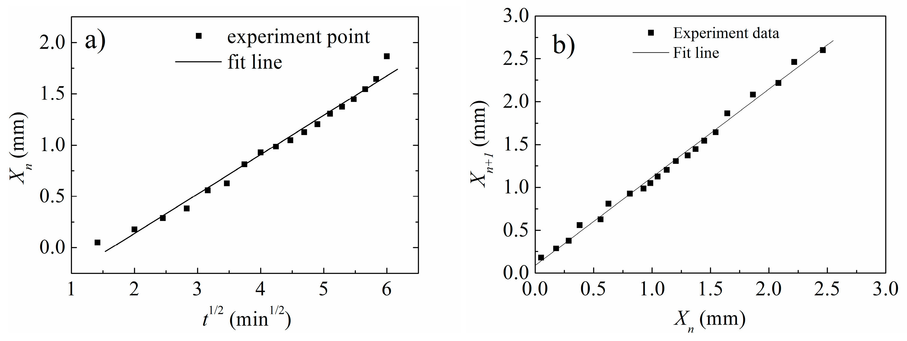
The ordered structure of L-MCHs via the reaction–diffusion process is visible in photographs. The striking feature is that these patterns obey time law and space law. Xn is the distance of the nth layer from the hydrogel surface and tn is the time elapsed before the formation of the nth layer. The quantitative rules between tn and Xn are known as time law, shown in Equation (2).
Xntn1/2
The plot of Xn vs. tn1/2 is shown in Figure 5a. The position of the nth layer (Xn) is proportional to the square root of elapsed time (tn1/2). This linear relationship of Xn and tn1/2 indicated that the diffusion of hydroxide ions in hydrogels obeys Fick’s second law. Examination of Figure 5a shows that the layered hydrogel obeys the time law successfully (relative coefficient R = 0.99), which indicated that the synthesis of a layered hydrogel is the consequence of the out-reactant diffused into the inner-reactant.
During the reaction–diffusion process for order-structured L-MCHs, the distribution of chitosan sol with iron ions is uniform, which will induce a linear relationship between the positions of two adjacent layers. According to the spacing law, the position ratio of successive layers from the gel interface approaches a constant value [26]. The position of the nth layer and (n+1)th layer follow a geometric series given by Equation (3):
Xn+1/Xn = 1 + p
The quantity (1 + p) is the spacing coefficient, which is a characteristic value for a particular system.
From Figure 5b it is clear that the plot shows a near-standard linear shape, which indicated that the tailored layer structure obeyed the spacing law.
The time law and spacing law from Figure 5 indicated that magnetic chitosan hydrogel with a tailored layer structure obeys the time law and spacing law of the classical reaction–diffusion process. The traditional reaction–diffusion phenomenon is based on the reaction of oppositely charged inorganic ions or oppositely charged “nanoionic” particles (Figure 1). One of the ions or “nanoionic” particles was dispersed in the hydrogel and the other ions or “nanoionic” particles diffused to the hydrogel and ordered-patterns were obtained. During the above process, the hydrogel only plays the role of the reaction medium which controls the diffusion behavior of the ions or “nanoionic” particles. Differently from the traditional reaction–diffusion phenomenon, the protonated chitosan (CS-NH3+) with iron ions (Fe3+ and Fe2+) was used as an inner-reactant and hydroxide ion (-OH) was used as an out-reactant in this paper. Moreover, the protonated chitosan (CS-NH3+) not only played the role of inner-reactant but also the reaction medium which controlled the diffusion behavior of the out-reactant (-OH).

3.4. Mechanical Properties of Layered Hydrogels

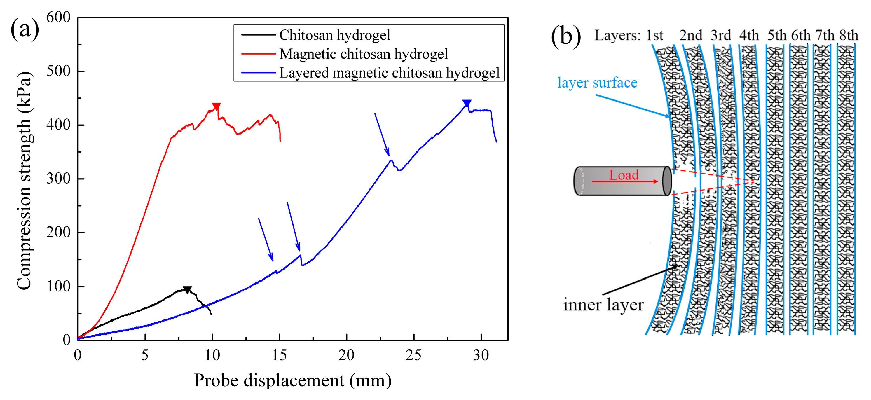
To demonstrate the influence of layer structure on the mechanical properties of hydrogels, we assessed the mechanical properties of chitosan hydrogel, magnetic chitosan hydrogel, and layered magnetic chitosan hydrogel. A Texture Analyzer was used for the hydrogels’ mechanical properties.
The results were shown in Figure 6 and Table 2. The chitosan hydrogel shows a yield strength of 95.1 ± 7.6 kPa. The yield strength of magnetic chitosan hydrogel was improved significantly (from 95.1 ± 7.6 kPa to 401.7 ± 12.1 kPa, about 4 times) when 10 wt. % magnetite nanoparticles were involved. The enhancement of the mechanical properties was due to the physical crosslinking effect of magnetite nanoparticles on chitosan. The correlations between magnetite nanoparticles and chitosan were discussed by our previous report, which gives evidence for the physical crosslinking effect of magnetite nanoparticles on chitosan [27]. The physical crosslinking effect was also substantiated by the results of Figure 4. For layered magnetic chitosan hydrogel, the yield strength reached 441.0 ± 15.1 kPa, which is about 10% higher than that of non-layered magnetic chitosan hydrogel.
The probe displacement when the rupture of chitosan hydrogel and magnetic chitosan hydrogel occurred was 8.2 ± 0.8 mm and 10.16 ± 1.3 mm, which means that they have similar toughness. It is worth noting that the probe displacement of layered magnetic chitosan hydrogel reached 28.93 ± 2.6 mm when the rupture occurred, which increased as high as 184.7 % compared with that of the non-layered hydrogel. Moreover, the compression curve of layered magnetic hydrogel expressed several Z-shaped steps (pointed by arrows in Figure 6), which was due to the layer structure of the hydrogel. During the reaction–diffusion process, the mobility of polymer chains was high enough near the diffusion front. With the concentration increase in hydroxide ions, the polymer chains entangled followed by their condensation onto the hydrogel to form a new layer surface (illustrated in Figure 1c). Thus, the polymer chain density of the layer surface was higher than that of the inner layer, which means that the mechanical properties of the layer surface would be higher than the inner layer. When the probe was loaded on the surface of the hydrogel (illustrated in Figure 6b), the polymer chains of the inner layer fractured before the failure of the layer surface. With the probe going forward, several layers fractured (e.g., the top three layers in Figure 6b) and the curve of the layered magnetic chitosan hydrogel began to drop. After that, the load was transformed to a new layer surface (e.g., the fourth layer surface in Figure 6b) and the curve began to increase again.
As we all know, the mechanical properties of commonly used hydrogels (such as collagen, gelatin, chitosan, agarose, and hyaluronic acid) are relatively low, which limits their applications. In order to improve the mechanical properties of hydrogels, chemical crosslinking is the most convenient method. However, chemical crosslinking will destroy the degradability of the hydrogels and also lead to some toxic side effects of the gel. The layered magnetic chitosan hydrogel provided a novel way for biocompatible hydrogel with enhanced mechanical properties. The layered structure and crosslinking effect of magnetite nanoparticles endow the layered magnetic chitosan hydrogel with enhanced yield strength and toughness, which makes it possible for their application as a tough implantable scaffold. Moreover, the magnetite nanoparticles also endow the layered magnetic chitosan hydrogel with magnetic field responsibility, which can further expand its application fields.

4. Conclusions

A modified RD process was used for layered chitosan hydrogel (L-CH) and layered magnetic chitosan hydrogel (L-MCH). During the modified RD process, the protonated chitosan (CS-NH3+) with iron ions (Fe3+ and Fe2+) was used as the inner-reactant and hydroxide ion (-OH) was used as the out-reactant in this paper. Moreover, the protonated chitosan (CS-NH3+) not only played the role of theinner-reactant but also the reaction medium which controlled the diffusion behavior of the out-reactant (-OH). The morphologies and structure of L-CH and L-MCH indicated that a series of ordered chitosan layers or magnetic chitosan layers were constructed. The layer width of L-CH and L-MCH can be tailored by varying interval times, T. Our approach greatly simplifies the processing for hydrogels with ordered layer structures. The mean layer width of L-MCH increased from 50 ± 5.8 μm to 90 ± 6.4 μm when the interval time T increased from 2 min to 5 min, respectively. The tailored layer structure of L-CH and L-MCH obeyed the time law and spacing law, which declared that the L-CH and L-MCH were constructed via the reaction–diffusion process. The tailored layer structure endows hydrogels with enhanced mechanical properties. For L-MCH, the probe displacement of layered magnetic chitosan hydrogels reached 28.93 ± 2.6 mm (as high as 284.7% compared with that of non-layered hydrogel) when the rupture occurred. The layered structure and crosslinking effect of magnetite nanoparticles endow the layered magnetic chitosan hydrogel with enhanced yield strength and toughness. Moreover, the magnetite nanoparticles also endow the layered magnetic chitosan hydrogel with magnetic field responsibility such that it can be used in the field of magnetic field-controlled drug release and tissue scaffold. The modified RD process could be generalized to numerous positively charged macromolecular polymers.

Author Contributions

Y.W. (Yongliang Wang): Writing—Review andEditing, Funding Acquisition, Conceptualization; Y.X.: Software; Y.W. (Yunfei Wang): Writing—Original Draft, Methodology; B.L.: Conceptualization, Investigation; C.W.: Visualization, Data Curation; Z.H.: Review andEditing; L.W.: Writing—Review and Editing. All authors have read and agreed to the published version of the manuscript.

Funding

This work was supported by the National Science Foundation of China (51602084) and the Heilongjiang Natural Science Foundation (YQ2019E030).

Data Availability Statement

Not applicable.

Conflicts of Interest

The authors declare no conflict of interest.

References

  1. Ribeiro, E.F.; Polachini, T.C.; Locali-Pereira, A.R.; Janzantti, N.S.; Quiles, A.; Hernando, I.; Nicoletti, V.R. Storage stability of spray- and freeze-dried chitosan-based pickeringemulsions containing roasted coffee oil: Color evaluation, lipid oxidation, and volatile compounds. Processes 2023, 11, 1048. [Google Scholar] [CrossRef]
  2. Jafernik, K.; Ładniak, A.; Blicharska, E.; Czarnek, K.; Ekiert, H.; Wiącek, A.E.; Szopa, A. Chitosan-based nanoparticles as effective drug delivery systems—A review. Molecules 2023, 28, 1963. [Google Scholar] [CrossRef] [PubMed]
  3. Zarrintaj, P.; Urbanska, A.M.; Gholizadeh, S.S.; Goodarzi, V.; Saeb, M.R.; Mozafari, M. A facile route to the synthesis of anilinic electroactive colloidal hydrogels for neural tissue engineering applications. J. Colloid Interface Sci. 2018, 516, 57. [Google Scholar] [CrossRef] [PubMed]
  4. Khubiev, O.M.; Esakova, V.E.; Egorov, A.R.; Bely, A.E.; Golubev, R.A.; Tachaev, M.V.; Kirichuk, A.A.; Lobanov, N.N.; Tskhovrebov, A.G.; Kritchenkov, A.S. Novel non-toxic highly antibacterial chitosan/Fe(III)-based nanoparticles that contain a deferoxamine—Trojan horse ligands: Combined synthetic and biological studies. Processes 2023, 11, 870. [Google Scholar] [CrossRef]
  5. Meira, D.I.; Proença, M.; Rebelo, R.; Barbosa, A.I.; Rodrigues, M.S.; Borges, J.; Vaz, F.; Reis, R.L.; Correlo, V.M. Chitosan micro-membranes with integrated gold nanoparticles as an LSPR-based sensing platform. Biosensors 2022, 12, 951. [Google Scholar] [CrossRef]
  6. Song, W.; Huang, T.; Zuo, H.; Deng, D.; Tang, C. Application of microbial immobilization on chitosan composite membrane for manganese removal in water treatment. Polymer 2022, 243, 124531. [Google Scholar] [CrossRef]
  7. Chen, J.; Yang, L.M.; Liu, Y.F.; Ding, G.W.; Pei, Y.; Li, J.; Hua, G.F.; Huang, J. Preparation and characterization of magnetic targeted drug controlled-release hydrogel microspheres. Macromol. Symp. 2005, 225, 71–80. [Google Scholar] [CrossRef]
  8. Sun, H.; Kabb, C.P.; Sims, M.B.; Sumerlin, B.S. Architecture-transformable polymers: Reshaping the future of stimuli-responsive polymers. Prog. Polym. Sci. 2019, 89, 61–75. [Google Scholar] [CrossRef]
  9. Liu, M.J.; Ishida, Y.; Ebina, Y.; Sasaki, T.; Hikima, T.; Hikima, T.; Takata, M.; Aida, T. An anisotropic hydrogel with electrostatic repulsion between cofacially aligned nanosheets. Nature 2014, 517, 68–72. [Google Scholar] [CrossRef]
  10. Sakr, O.S.; Jordan, O.; Borchard, G. Sustained protein release from hydrogel microparticles using layer-by-layer (LbL) technology. Drug Deliv. 2015, 23, 2747–2755. [Google Scholar] [CrossRef] [Green Version]
  11. Dedroog, L.M.; Deschaume, O.; Abrego, C.J.G.; Koos, E.; de Coene, Y.; Vananroye, A.; Thielemans, W.; Bartic, C.; Lettinga, M.P. Stress-controlled shear flow alignment of collagen type I hydrogel systems. Acta Biomater. 2022, 150, 128–137. [Google Scholar] [CrossRef] [PubMed]
  12. Roehm, K.D.; Madihally, S.V. Bioprinted chitosan-gelatin thermosensitive hydrogels using an inexpensive 3D printer. Biofabrication 2018, 10, 015002. [Google Scholar] [CrossRef] [PubMed]
  13. Tran, K.A.; Jin, Y.; Bouyer, J.; DeOre, B.J.; Suprewicz, L.; Figel, A.; Walens, H.; Fischer, I.; Galie, P.A. Magnetic alignment of injectable hydrogel scaffolds for spinal cord injury repair. Biomater. Sci. 2022, 10, 2237–2247. [Google Scholar] [CrossRef]
  14. Grzybowski, B.A.; Bishop, K.J. Micro- and nanoprinting into solids using reaction-diffusion etching and hydrogel stamps. Small 2009, 5, 22–27. [Google Scholar] [CrossRef]
  15. Erb, R.M.; Sander, J.S.; Grisch, R.; Studart, A.R. Self-shaping composites with programmable bioinspired microstructures. Nat. Commun. 2013, 4, 1712. [Google Scholar] [CrossRef] [PubMed] [Green Version]
  16. Hinton, T.J.; Jallerat, Q.; Palchesko, R.N.; Park, J.H.; Grodzicki, M.S.; Shue, H.-J.; Ramadan, M.H.; Hudson, A.R.; Feinberg, A.W. Three-dimensional printing of complex biological structures by freeform reversible embedding of suspended hydrogels. Sci. Adv. 2015, 1, e1500758. [Google Scholar] [CrossRef] [Green Version]
  17. Kumar, S.; Jiwari, R.; Mittal, C. Numerical simulation for computational modelling of reaction–diffusion Brusselator model arising in chemical processes. J. Math. Chem. 2019, 57, 149–179. [Google Scholar] [CrossRef]
  18. Jonášová, E.P.; Stokke, B.T.; Prot, V. Interrelation between swelling, mechanical constraints and reaction–diffusion processes in molecular responsive hydrogels. Soft Matter 2022, 18, 1510–1524. [Google Scholar] [CrossRef]
  19. Walliser, R.M.; Boudoire, F.; Orosz, E.; Tóth, R.; Braun, A.; Constable, E.C.; Rácz, Z.; Lagzi, I. Growth of nanoparticles and microparticles by controlled reaction-diffusion processes. Langmuir 2015, 31, 1828–1834. [Google Scholar] [CrossRef] [Green Version]
  20. Campbell, C.J.; Baker, E.; Fialkowski, M.; Grzybowski, B.A. Arrays of microlenses of complex shapes prepared by reaction-diffusion in thin films of ionically doped gels. Appl. Phys. Lett. 2004, 85, 1871–1873. [Google Scholar] [CrossRef]
  21. Klajn, R.; Fialkowski, M.; Bensemann, I.T.; Bitner, A.; Campbell, C.J.; Bishop, K.; Smoukov, S.; Grzybowski, B.A. Multicolour micropatterning of thin films of dry gels. Nat. Mater. 2004, 3, 729–735. [Google Scholar] [CrossRef]
  22. Lagzi, I.; Kowalczyk, B.; Grzybowski, B.A. Liesegang Rings Engineered from Charged Nanoparticles. J. Am. Chem. Soc. 2010, 132, 58–60. [Google Scholar] [CrossRef] [PubMed] [Green Version]
  23. Li, B.; Gao, Y.; Feng, Y.; Ma, B.; Zhu, R.; Zhou, Y. Formation of concentric multilayers in a chitosan hydrogel inspired by liesegang ring phenomena. J. Biomater. Sci. Polym. Ed. 2011, 22, 2295–2304. [Google Scholar] [CrossRef] [PubMed]
  24. Wang, Y.; Li, B.; Zhou, Y.; Han, Z.; Feng, Y.; Wei, D. A facile concentric-layered magnetic chitosan hydrogel with magnetic field remote stimulated drug release. J. Control. Release 2013, 172, e90. [Google Scholar] [CrossRef]
  25. Dai, H.; Li, X.; Long, Y.; Wu, J.; Liang, S.; Zhang, X.; Zhao, N.; Xu, J. Multi-membrane hydrogel fabricated by facile dynamic self-assembly. Soft Matter 2009, 5, 1987–1989. [Google Scholar] [CrossRef]
  26. Rajurkar, N.; Ambekar, B. Studies on Liesegang rings of cobalt hydroxide in 1% agar gel medium. J. Mol. Liq. 2015, 204, 205–209. [Google Scholar] [CrossRef]
  27. Wang, Y.; Li, B.; Xu, F.; Han, Z.; Wei, D.; Jia, D.; Zhou, Y. Tough magnetic chitosan hydrogel nanocomposites for remotely stimulated drug release. Biomacromolecules 2018, 19, 3351–3360. [Google Scholar] [CrossRef]
Figure 1. Schematic representation of construction methods for composites with ordered layer structure inspired by the reaction–diffusion process. (a) RD process based on inorganic anion and cation precipitation. (b) RD process based on charged nanoparticle precipitation. (c) RD process based on positively charged macromolecular polymer.
Processes 11 01975 g001
Figure 2. Principle of synthesis of hydrogels with ordered structure. Strategy 1: if axial diffusion is used, the parallel layered hydrogel will be obtained. Strategy 2: if radial diffusion is used, the concentric layered hydrogel will be constructed.
Processes 11 01975 g002
Figure 3. Morphologies of layered chitosan hydrogel (L-CH). (a) Vertical section morphology of L-CH via a super-high magnification 3D microscope. (b) Cross-section morphology of L-CH via ESEM.
Processes 11 01975 g003
Figure 4. ESEM morphologies of L-CHs and L-MCHs via different interval times, T. (a) L-CH when T was 2 min. (b) L-CH when T was 5 min. (c) L-CH when T was 10 min. (d) L-MCH when T was 2 min. (e) L-MCH when T was 5 min. (f) L-MCH when T was 10 min.
Processes 11 01975 g004
Figure 5. (a) Plot of the position of the nth layer Xn to the square root of elapsed time tn1/2. (b) The layer position relationship of the Xn layer and Xn+1 layer.
Processes 11 01975 g005
Figure 6. Compression testing profiles of chitosan hydrogel, magnetic chitosan hydrogel, and layered magnetic chitosan hydrogel. (a) Compression testing profiles. (b) Illustration of rupture of layered hydrogel. Note: the maximum strength is indicative of “yield strength” and the probe displacement of yield strength is “toughness”.
Processes 11 01975 g006
Table 1. The layer number and layer width of L-CHs and L-MCHs with different interval times, T.
T (min)L-CHsL-MCHs
Layer NumberWidth of Layer (μm)Layer NumberWidth of Layer (μm)
246 ± 380 ± 4.248 ± 350 ± 5.8
522 ± 2140 ± 7.324 ± 290 ± 6.4
1014 ± 1648 ± 10.310 ± 1487 ± 9.8
Table 2. Mechanical properties of chitosan hydrogel, magnetic chitosan hydrogel, and layered magnetic chitosan hydrogel.
SamplesYield Strength (kPa)Probe Displacement (mm)
Chitosan hydrogel95.1 ± 7.68.2 ± 0.8
Magnetic chitosan hydrogel401.7 ± 12.110.16 ± 1.3
Layered magnetic chitosan hydrogel441.0 ± 15.128.93 ± 2.6
Disclaimer/Publisher’s Note: The statements, opinions and data contained in all publications are solely those of the individual author(s) and contributor(s) and not of MDPI and/or the editor(s). MDPI and/or the editor(s) disclaim responsibility for any injury to people or property resulting from any ideas, methods, instructions or products referred to in the content.