Review

Review of the Research on and Optimization of the Flow Force of Hydraulic Spool Valves

1
School of Mechanical Engineering, Qilu University of Technology (Shandong Academy of Sciences), Jinan 250353, China
2
Shandong Machinery Design and Research Institute, Jinan 250353, China
3
Weichai Lovol Intelligent Agricultural Technology CO., LTD, Weifang 261000, China
*
Author to whom correspondence should be addressed.
Processes 2023, 11(7), 2183; https://doi.org/10.3390/pr11072183
Submission received: 14 June 2023 / Revised: 18 July 2023 / Accepted: 19 July 2023 / Published: 21 July 2023

Abstract

:
As one of the important factors affecting the stability of slide valves, the analysis and research of flow force are of great significance. In recent years, more and more experts and scholars have conducted research in this field, attempting to find methods to reduce or utilize the flow force of hydraulic spool valves. Flow force includes steady-state flow force and transient flow force, with steady-state flow force having the most significant impact on spool valves. The influencing factors of flow force are complex and diverse, including the cavitation phenomenon, shape of the throttling groove, and jet angle. At present, the main ways to reduce flow force are to design the structure of the spool valve, the structure of the valve sleeve, and the flow channel of the valve body. This article mainly reviews the definition, calculation methods, influencing factors, and methods for reducing the flow force of slide valves. This provides a new approach to reducing the flow force in hydraulic spool valves.

1. Introduction

Hydraulic transmission technology has the advantages of a flexible layout and high transmission efficiency, occupying an important position in modern engineering [1,2,3,4,5]. However, some precision hydraulic valves, hydraulic pumps, and other important hydraulic components are basically produced by foreign manufacturing companies. Therefore, most of China’s engineering equipment has been influenced by foreign high-precision hydraulic components. Hydraulic spool valves are common control components in hydraulic systems, mainly used to control the flow, pressure, and flow direction of hydraulic oil [5,6,7,8]. Therefore, studying the stability of their work is of great significance. The working principle of hydraulic spool valves is to control the hydraulic system by controlling the flow of fluid. In hydraulic spool valves, fluid changes as it flows through the valve port, resulting in steady-state and transient flow forces. Steady-state flow force refers to the hydrodynamic phenomenon generated by a fluid in a stable flow state, mainly divided into axial flow force and radial flow force [9,10,11,12]. Axial flow force refers to the flow force generated by a fluid in the axial direction of the valve port, which is caused by the change in velocity of the liquid as it flows through the valve port [13,14,15,16,17,18]. Radial flow force refers to the flow force generated by the fluid in the radial direction of the valve port, which is caused by the interference of the valve core when the liquid flows through the valve port. Transient flow force refers to the instantaneous hydrodynamic phenomenon that occurs when a fluid suddenly closes or opens at the valve port. When the valve port is closed, a reverse transient flow force may be generated due to the inertia of the liquid, which may have adverse effects on the hydraulic system. Therefore, when designing hydraulic spool valves, it is necessary to consider the impact of transient flow forces and take corresponding measures to reduce their impact [19,20]. Fumio SHIMIZU [21] used CFX three-dimensional calculation and analysis to display the flow field in spool valves and to elucidate the mechanism of flow force acting on said valves. As an interference force, flow force has strong randomness and instability as it varies with the flow rate and opening size of the valve, greatly limiting the static and dynamic control performance of hydraulic spool valves. In recent years, methods to reduce flow forces have become a focus of research by scholars both domestically and internationally. There are three main methods to reduce the steady-state flow force of hydraulic spool valves: Designing the valve core structure, designing the valve sleeve structure, and designing the valve body flow channel. Amirante [22,23,24], Li [25], and others had changed the structure of the valve core to reduce the flow force. Tang [26] used the movement of the valve sleeve to change the opening amount of the valve port, thereby reducing the generation of flow force. Li [27] and Lisowski [28] reduced the flow force by changing the structure of the valve body. Due to many scholars’ belief that radial and transient flow forces have little impact on the working performance of hydraulic spool valves, there is currently little research on radial and transient flow forces. In summary, the hydrodynamic phenomenon in hydraulic spool valves is an important factor that restricts their performance and reliability, and we need to pay attention to it in design and use.
In summary, reducing flow force has become one of the important means and trends for modern hydraulic spool valve manufacturing enterprises to grow and establish themselves in complex markets. Hydraulic spool valves, as basic components, are widely used in hydraulic systems. Therefore, studying the flow force of spool valves can help further improve the accuracy and stability of hydraulic systems, as well as point out relevant directions for the current development of hydraulic systems.

2. Hydrodynamic Analysis

2.1. Steady-State Flow Force

Steady-state flow force, also known as Bernoulli force, mainly refers to the additional force exerted by the liquid medium on the valve core due to the fluid flow in the hydraulic valve without time-varying flow. It is the main factor affecting the working and control performance of the slide valve, which is mainly divided into axial flow force and radial flow force.

2.1.1. Axial Flow Force

The axial steady-state flow force acts on the wall in the same direction as the axis of the valve core, and its basic calculation formula is:
F = ρ   Q   v   c o s θ .
In the formula, v is the flow velocity; ρ is the density of the oil; θ is the jet angle of the beam; Q is the flow rate.
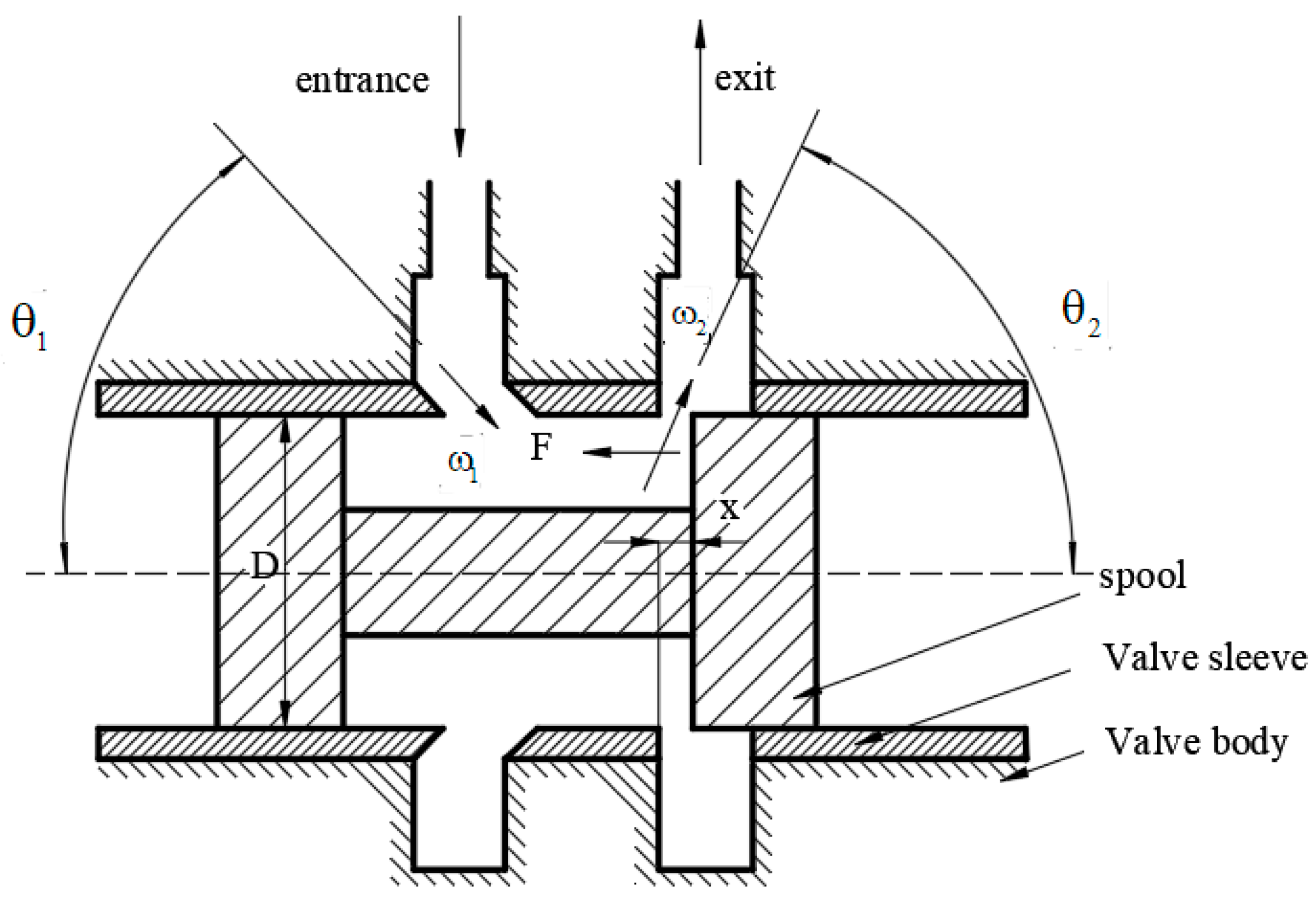
As shown in Figure 1, the force surface of the axial steady-state flow force includes the left and right walls of the valve core, the axial wall surface, the inner wall surface of the valve sleeve, and the wall surface of the throttle port [29,30]. On these stress surfaces, the momentum of the liquid changes, generating flow forces [31,32,33]. When the radial flow force is already balanced, the momentum formula for the axial flow force can be obtained based on the momentum theorem:
F = ρ   Q   v 2   c o s θ 2 ρ   Q   v 1   c o s θ 1 .
In the formula, v1 and v2 are the inflow and outflow velocities, respectively; θ1 and θ2 are the jet angles at the inlet and outlet, respectively.

2.1.2. Radial Flow Force

When studying radial steady-state flow force, most scholars believe that a structurally symmetrical valve core has a radial flow force in equilibrium. However, radial flow force is related to hydraulic clamping force. For some structurally complex spool valves, their stress environment is more complex, and radial flow force is inevitable. By modeling the internal fluid of the hydraulic directional valve as a whole and fully considering the clearance leakage of the hydraulic valve, Wang [34] derived a solution for radial steady-state flow force. He used the Bernoulli equation to analyze the flow of liquid in a hydraulic directional valve and proposed a new calculation method. He pointed out that due to the uneven distribution of pressure, hydraulic spool valves will show a trend of overall eccentricity and tilt, ultimately leading to hydraulic clamping of said valves.
At the high-pressure outlet step, the pressure difference is large and the hydraulic clamping phenomenon is relatively serious. At the steps of the low-pressure oil return port and the high-pressure inlet, although the pressure difference is small, there is also a problem of clamping force. Therefore, when calculating the flow force acting on a spool valve, it is also necessary to consider the influence of radial flow force. Zheng [35] studied the relationship between spool valve diameter and radial flow force and obtained a steady-state flow force equation with correction coefficients, as shown in Formulas (3) and (4). Experiments have shown that as the diameter of the journal increases, the axial steady-state flow force decreases, while the radial steady-state flow force increases.
F s = ρ   q v 2 ω c s 1   c o s α 1 x 1 c s 2   c o s α 2 x 2 .
F r = ρ   q v 2 ω c r 1   s i n α 1 x 1 + c r 2   s i n α 2 x 2 .
In the formula, cs1 and cs2 are the correction coefficients for axial steady-state flow force; cr1 and cr2 are the correction coefficients for radial flow force.
Lu [36] used CFD to analyze the interior of slide valves and used the Bernoulli equation and segmented method to theoretically analyze the radial flow force generated by the fluid in the valve chamber. Research has shown that the larger the opening of the valve port of a hydraulic spool valve, the smaller the radial flow force fluctuation acting on said valve. This is because the flow speed of the liquid increases when passing through the valve port, leading to an increase in liquid momentum, thereby reducing the fluctuation of radial flow force. Second, as the inlet flow rate increases, the depth-to-diameter ratio of the ring cutting groove gradually decreases and the radial pressure fluctuation gradually increases. This is because as the flow rate increases, the flow rate of the liquid in the ring cutting groove increases and the liquid momentum increases, resulting in an increase in the fluctuation of radial pressure. In addition, compared to the inlet and outlet shaft intersection angles of 0° and 90°, when the inlet and outlet shaft intersection angles are 180°, the radial pressure distribution of the x = 0 section is more uniform. This is because when the inlet and outlet shaft intersection angles are 180°, the flow direction of the liquid is more consistent with the movement direction of a spool valve, resulting in a more uniform distribution of radial flow force. The radial flow force also seriously affects the hydraulic clamping force. In the case of a high flow rate and a small ring cutting groove depth-to-diameter ratio, the clamping force can cause the spool valve to be eccentric and inclined.
Thermal deformation and solid particles can also affect the hydraulic clamping force. Chen et al. [37,38] measured the temperature of slide valve cores with K, U, and V throttling slots using the in situ measurement method of temperature distribution embedded with micro-thermocouples. They found that a smaller valve opening results in a large temperature gradient in spool valves, and as the spool valve opening or pressure difference increases, the local high-temperature zone on the throttling edge gradually expands. They designed a spool valve hysteresis force measurement device with a constant temperature control function, which accurately measures the hysteresis force of a spool valve under thermal deformation, solid particles, and the coupling effect of thermal deformation and solid particles. The conclusion was drawn that the hysteresis force of slide valves exhibits obvious pulsating characteristics and the temperature of spool valves, thermal deformation, and hysteresis force are positively correlated. They established a mechanical model of spool valve hysteresis under the action of solid sensitive particles and discovered the micro-mechanism by which a throttle temperature rise leads to local high temperature in a spool valve and a temperature difference between the spool valve and valve body, resulting in a smaller fit gap and an increase in particle sensitivity within the gap, in turn causing a decrease in the radial micro-motion clearance of the spool valve. In the case of changes in the position of a spool valve and contact between the particle and micro-morphology gap wall, the hysteresis force of the spool valve suddenly increases.

2.2. Transient Flow Force

In traditional methods of studying flow force, people often overlook transient flow force because it is much smaller than steady-state flow force. However, since hydraulic control valves are often used for a faster response, it is important to have a better understanding of transient flow force. In 1967, Merritt [39] used Newton’s Second Law, the approximate values of fluid acceleration and mass, to derive the transient and steady-state flow force acting on the spool valve in his article. In the analysis of transient flow force, he proposed two transient terms: A term proportional to the spool valve velocity and a term proportional to the system pressure transient. In this article, Merritt believed that the velocity term is more important, while neglecting the influence of pressure transients without strict proof. In order to investigate the impact of transient flow force acting on slide valves, Nakada et al. [40] compared their experimental results with a flow force model that ignored transient flow force, and they found that the phase angle was slightly different at higher frequencies. Unfortunately, the authors attributed the reason to the assumptions of the model and limitations of the instrument. Del Vescovo and Lipolis [41] used two-dimensional computational fluid dynamics (CFD) analysis and dynamic grid techniques to consider transient flow force. This work investigated the effects of spool valve motion and pressure transient on the total flow force applied to valves. The results indicated that when the oscillation frequency increases to above 100 Hz, the sinusoidal change in pressure begins to affect the flow force. The strongest effect of convective dynamics was observed at frequencies above 1000 Hz. In order to study the transient effect of pressure from an experimental perspective and to qualitatively evaluate the advantages and disadvantages of existing models, Manring [42] utilized an experimental setup from the University of Missouri to generate pressure transient effects in hydraulic circuits, which was used to create a time rate of change of volumetric flow through a bidirectional spool valve. The results indicated that the flow force caused by the transient effect of pressure could be comparable in magnitude to the stable flow force acting on the valve, and the tradition of ignoring this effect in the past may not always be reasonable. Guo [43] and Yin [44] found that the changes in spool valve motion speed and pressure mainly affect the magnitude of transient hydraulic force. In the design of solenoid valves, the influence of transient flow force is often ignored, which is also one of the main reasons for the unstable operation of solenoid valves.

3. Factors Affecting Flow Force

3.1. Cavitation Phenomenon

Cavitation is a phase transition phenomenon that occurs in a fluid system under certain conditions [45,46,47]. If the dynamic change of static absolute pressure reaches or drops below the vapor pressure of the liquid, steam bubbles are formed inside the fluid. When subjected to areas with higher pressure, steam bubbles will rupture. Cavitation is a common harmful phenomenon in hydraulic components and systems. It not only disrupts the continuity of flow and alters physical properties, but in many cases, it can also lead to unwanted effects such as strong noise, vibration, and erosion of solid surfaces affected by it. Therefore, study of the cavitation phenomenon is of great significance.
Chen [48] analyzed the cavitation phenomenon in hydraulic servo valves by studying the flow in the middle gap of said valves. According to analysis of the steam volume fraction, cavitation occurred in the gap between the valve seat and spool valve. It can be concluded that cavitation occurs in areas where the static pressure is lower than the water vaporization pressure and in areas where the flow rate is very high. Li [49] studied the flow force and cavitation phenomenon in the pilot stage of an electro-hydraulic servo valve from the perspective of temperature. Due to the small and complex flow field of the electro-hydraulic servo valve, the extreme temperature environment intensified the self-oscillation, resulting in the decline of the control accuracy of the servo valve. With the increase in temperature, the size of the orifice, the temperature characteristics of the fluid, and the pressure loss in the flux tube affected the characteristics of the pilot stage. The results indicate that as the temperature increased, the viscosity of the oil rapidly decreased and the flow force acting on the baffle increased. When the temperature exceeded 50 °C, the influence of oil viscosity was relatively small and the flow rate of the electro-hydraulic servo valve was less affected by temperature. In addition, due to the combined effects of pressure loss and temperature on the servo valve parameters, the flow force tended to slightly decrease. Lower oil viscosity led to a higher Reynolds number in the flow field of the pilot stage, which inevitably lea to more intense turbulent jet phenomenon, thus inducing stronger cavitation dynamics. The phenomenon of cavitation exists throughout the entire testing process. The higher the fluid temperature, the more obvious the cavitation phenomenon in the flow field. Extreme temperature environments may exacerbate self-deterioration, leading to a decrease in the control accuracy of electro-hydraulic servo valves. To suppress cavitation, Aung [50] proposed a new baffle shape. To eliminate the curved edges in traditional baffle shapes, a simple rectangular shape was chosen as the innovative baffle shape. The selected innovative baffle shape does not require any changes to the structure of the pilot stage components. It is expected to guide and weaken the aggressive radial jet along the extended flat wall until it moves away from the stagnation zone. In this way, the acceleration zone near the stagnation zone on the curved edge of the flap will be eliminated and cavitation will be suppressed. In addition, it will eliminate the lateral force of the shedding vortex. The innovative baffle shape is expected to provide cavitation suppression advantages without interrupting the flow control performance of the pilot stage, including leakage flow, which is considered a source of power loss in servo valves.

3.2. Jet Angle

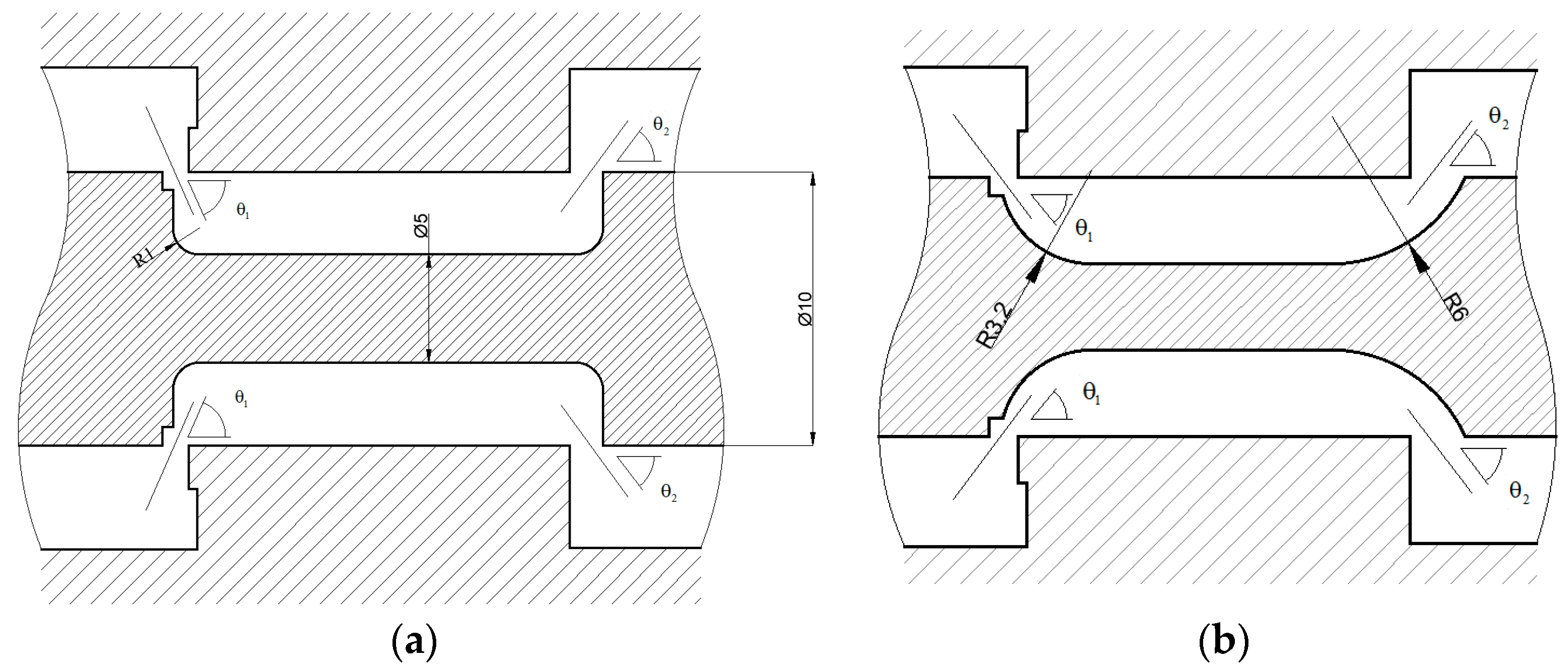
According to the basic formula of steady-state flow force, the flow force is related to the jet angle. The flow force is minimal when the jet angle is 69°, but the premise of forming a 69° exit angle is that the spool shoulder where the valve port is located must be an acute angle when a certain radial clearance is guaranteed [51]. In addition, the flow channel structure in the valve body directly affects the size of the jet angle, thus affecting the hydraulic power. Zhang et al. [52] used an innovative scheme to reduce the jet angle on the inner wall of the spool, thereby reducing the flow force. As shown in Figure 2, at the inlet of a traditional spool valve, the axial wall surface is perpendicular to the longitudinal wall surface, with only small rounded corners. In the innovative solution, the direction of the longitudinal wall surface is changed, resulting in a curved transition shape for the entire diversion wall. This change results in a change in the flow direction of the liquid when passing through a spool valve, resulting in a decrease in the jet angle flow force. Through analysis of the CFD fluid simulation results, the following conclusions can be drawn: First, the spool of a traditional hydraulic slide valve has a local high-pressure area and a local low-pressure area, while the spool of the hydraulic slide valve using the innovative scheme has a circular flow guide wall, resulting in a more uniform pressure field distribution and no obvious pressure concentration area. Second, the inner wall of the optimized solution exhibits a circular transition shape and has a certain guiding effect, resulting in a smoother distribution of the liquid flow velocity and a more natural transition. In contrast, the velocity field of traditional schemes is relatively chaotic, with discontinuous transitions and more pronounced rapid impacts on the wall. Therefore, optimizing the inner wall of a spool valve can significantly reduce the steady-state hydraulic force on said valve. The new hydraulic spool valve structure reduces the flow force by nearly 60% compared to traditional structures. This optimization scheme can significantly improve the mechanical and control performance of proportional servo valves. It can be seen that optimizing the structure of hydraulic spool valves can effectively improve their control performance and reliability, thereby improving the efficiency and stability of the hydraulic system.
In addition, the jet angle is also related to the fitting clearance, valve opening, and flow rate. Qu et al. [53] established a mathematical model for the flow force of an internal flow spool valve to address the issue of pressure regulation accuracy of an electro-hydraulic proportional relief valve. Based on the CFD simulation platform, a spool valve model considering fit clearance was constructed, and an experimental platform was built to verify the correctness of the model. The research results indicated that when the valve opening is small, the change rate of jet angle on the fit clearance is relatively large. As the opening gradually increases, the effect of the fitting gap on the jet angle gradually decreases. At the same opening, as the fit gap increases, the jet angle gradually decreases. This study has guiding significance for further improving the pressure regulation accuracy of electro-hydraulic proportional relief valves and it provides an important theoretical basis for designing and optimizing more efficient slide valves.

3.3. Flow Rate

The steady-state flow force increases with the increase in flow rate [54]. Gao [55] and Zhang et al. [56] analyzed the influence of steady-state flow force on the performance of large-flow directional control valves and concluded that the main reason for the problems in the operation of said valves was the change of steady-state flow force. Deng et al. [57]. found that after a multi-way spool valve is opened, the larger the spool stroke, the larger the output flow rate, which remains unchanged after reaching the maximum value. With the increase in spool stroke, the steady-state fluid power on the spool of a multi-way valve first increases and then decreases. The direction of steady-state flow force is opposite to the direction of spool movement, so that the valve port tends to be closed and the increase in load leads to a decrease in steady-state flow force. The fluid flow control of hydraulic valves mainly depends on the throttling form of the notch [58,59]. Ye et al. [60] proposed three kinds of throttling grooves with different structural characteristics, namely, spherical grooves, triangular grooves, and divergent U-shaped grooves. Through CFD analysis, it was found that the steady-state flow force of triangular and divergent U-shaped grooves increases roughly linearly with the increase in openings. The difference between the calculated steady-state flow force at the same opening and the corresponding test value increases gradually with the increase in opening. When the notch is close to the full open state, the flow resistance of the throttling section almost disappears. When the velocity increases rapidly, the measured value of steady-state flow force increases suddenly. Yao [61] and others used Fluent to conduct static simulation on U-shaped, K-shaped, and U + K combined throttling groove slide valves and obtained the steady-state hydrodynamic characteristics of three types of throttling grooves. The flow rate of K-shaped slot slide valves has a good linear property with the increase in valve opening, and the U + K combination slot has flow fluctuations at the junction. The steady-state flow force of the two types of throttling slots is negative, both pointing at the direction of closing the valve port and gradually increasing with the increase in valve port opening.

4. Methods for Reducing Flow Force

4.1. Axial Steady-State Flow Force

In order to reduce the impact of axial steady-state flow force on the performance of hydraulic spool valves, common methods for compensating flow force mainly include the structural design of a spool valve, structural design of the valve sleeve, and flow channel design of the valve body.

4.1.1. Structural Design of Spool Valves

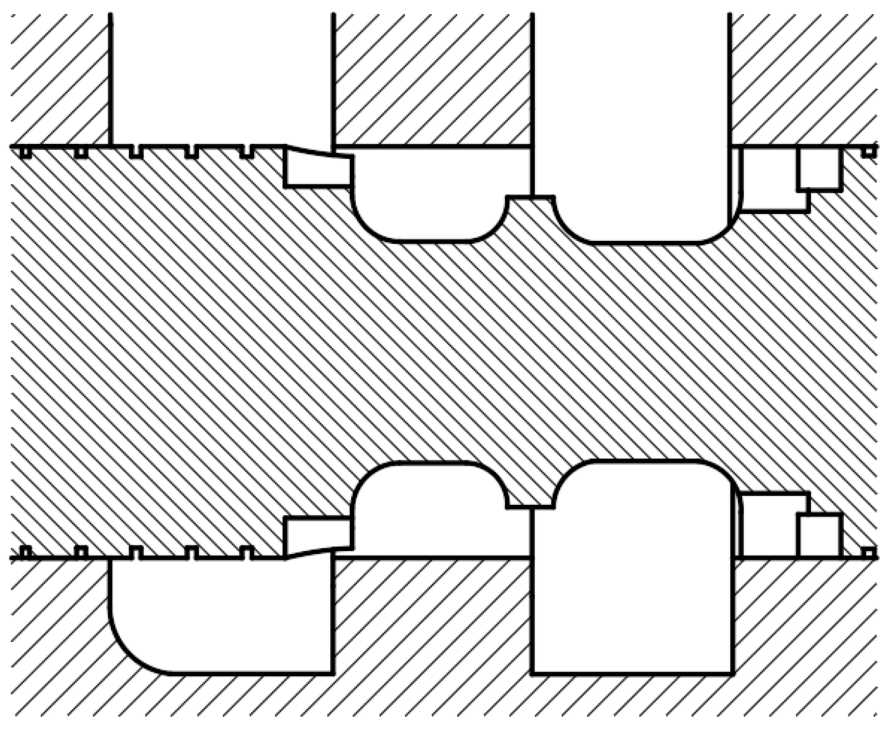
At present, the structural design of spool valves is mainly based on the principle of steady-state flow force, and the impact of steady-state flow force on the operational performance of spool valves is reduced by adding or changing the structure [62,63,64,65,66]. This optimization method has a simple principle and a direct obstruction effect on the liquid flow, which can significantly reduce the flow force. Zhou et al. [67] proposed a method to reduce steady-state flow forces using a convex structure, as shown in Figure 3. The principle of this method is to guide high-speed liquid flow to the valve body wall surface through a circular convex platform, thereby reducing the flow rate of the liquid flow. Reducing the liquid flow rate directly impacts the right end of the spool valve, thereby reducing the impact force on the right end of the spool valve and ultimately reducing the steady-state flow force of the entire spool valve. They extracted flow channels for multi-way valves assembled with annular protrusion valve cores of five sizes (13, 14, 15, 16, and 17 mm) and conducted simulation. The pressure inlet was set at 10 MPa, the outlet pressure was constant at 0.5 MPa, and the opening degrees were set at 2.1 and 4.0. The improvement of the diameter of each annular protrusion was calculated as shown in Table 1 [67]. As the diameter of the annular convex platform increases, the steady-state flow force on the spool valve decreases first and then increases for a throttling groove that is not fully opened. For a fully opened throttling groove, the steady-state flow force on the spool valve shows a continuous decreasing trend. Meanwhile, as the diameter of the annular convex platform increases, the flow loss also gradually increases. This research result provides an important reference basis for valve design and optimization. By adjusting the diameter of the circular convex platform, the steady-state flow force on a spool valve can be effectively reduced, thereby improving the performance and reliability of said valve. In addition, this study provides new ideas for research in the field of fluid control and important theoretical guidance for the development and application of related technologies. Chen et al. [68] designed a circular step structure based on an open center multi-way valve in the bucket machine. As shown in Figure 4, this circular step structure can reduce the flow force below the reset spring force value, preventing the valve core from clamping. At the same time, it reduces the impact on the slide valve wall, achieving the expected effect of reducing the peak flow force.
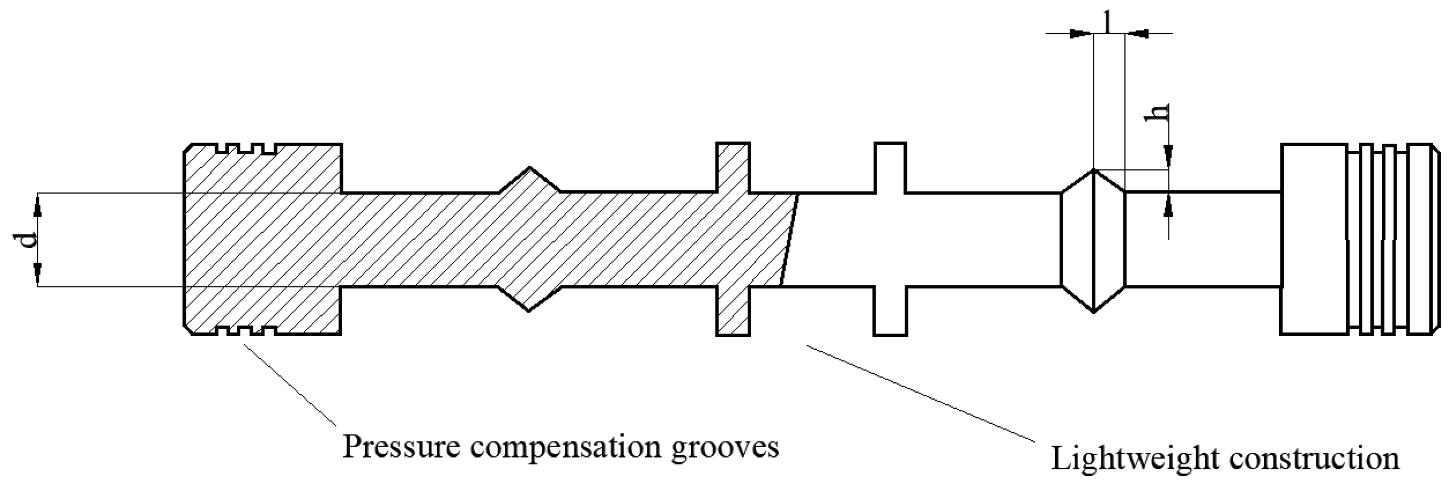
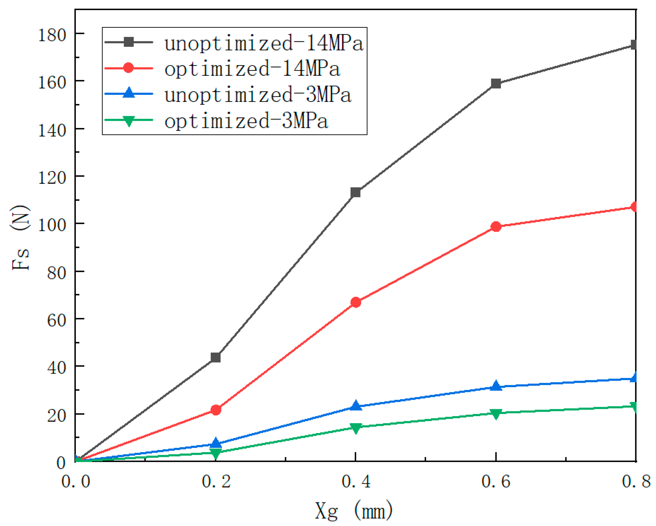
Gui [69,70] also studied this method and proposed a hydrodynamic optimization design for the spool valve of a piezoelectric servo valve. Figure 5 shows the spool valve structure, while Figure 6 shows the optimization of the control room. The structural optimization of the spool valve mainly involves setting six pressure compensation slots to reduce the Coulomb friction Fk and setting compensation profiles to reduce the steady-state flow force FS by changing the injection angle. The compensation contour has two main design parameters, namely, the height of the compensation contour and the half-width of the compensation contour. The compensation contour is set in the middle position of the L2 section of the spool valve, which is exactly opposite the A B port when the spool valve is in the zero position. This design ensures that the compensation profile can guide fluid to the orifice of the valve sleeve, which corresponds to ports A and B under different spool valve openings. Table 2 and Figure 7 [69] show the effect of optimized structure on steady-state flow force. The results indicate that optimization has a significant impact on the flow force. From Table 2, when d = 5.7 mm, l = 1.98 mm, and h = 1.05 mm, the steady-state flow force is the smallest. From Figure 7, as the valve port pressure increases, the optimization design has a more significant effect on reducing the flow force, and the smaller the valve port opening, the better the optimization effect.
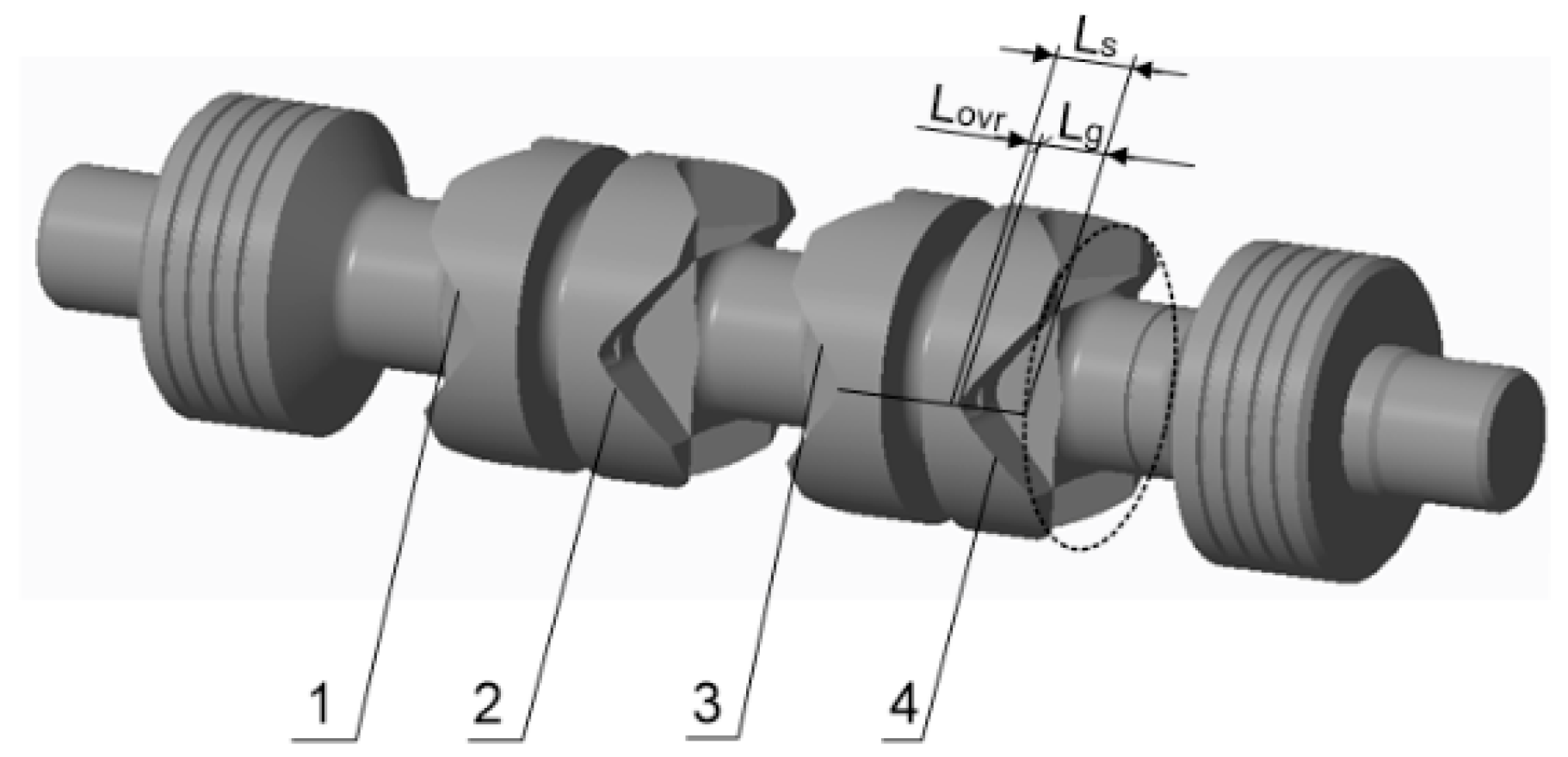
As shown in Figure 8, Lisowski [71,72] added a cylindrical notch with a diameter of 2 mm at the vertex of the main groove of a proportional spool valve to reduce axial and radial flow forces. Through CFD simulation, it can be concluded that using a single small notch can significantly reduce the axial flow force acting on a spool valve, but at the same time, it can lead to radial hydraulic asymmetry on said valve. By setting two symmetrical notches, both the reduction of motion resistance and the reduction of radial flow force can be achieved. According to the research of Dong et al. [73], based on CFD simulations on V-shaped grooves of different depths, it can be concluded that the smaller the depth of the V-shaped groove, the smaller the steady-state flow force on a spool valve, but greater fluctuations will occur. Therefore, increasing the depth of the V-shaped groove appropriately is beneficial for reducing the vibration of a spool valve. It should be noted that the depth adjustment of the V-shaped groove should comprehensively consider the performance requirements and manufacturing difficulty of the hydraulic system to achieve the best design effect.
Another method is to maintain the original throttling groove and valve stem structure of spool valves, and only change the size of a certain structure of the valves to meet the design requirements of said valve. This optimization method does not have any requirements for the machining process of slide valves, but it requires a large amount of data for comparative calculation and analysis. It also puts forward high requirements for the selection of optimization methods and the accuracy of the results. Guan [74] optimized the design of U-shaped throttling grooves with different structural sizes. The study consisted of two main steps: The first step was to use MATLAB to calculate the flow area of U-shaped throttling grooves with different structural sizes; the second step was to simulate and analyze the steady-state flow force of U-shaped throttling grooves of different sizes and draw conclusions based on the simulation results. In the first step, the structural size of each U-shaped throttling slot was determined by calculating the flow area of different sized U-shaped throttling slots. In the second step, simulation analysis was conducted on the steady-state flow force of U-shaped throttling grooves of different sizes. Through simulation, the steady-state hydrodynamic characteristics of U-shaped throttling grooves of different sizes under different working conditions were elucidated. The simulation results showed that the larger the hydraulic diameter, the larger the flow area; meanwhile, the smaller the aspect ratio, the larger the flow area. When the pressure difference on both sides of the valve port was constant, the depth of the U-shaped groove was the same and the steady-state flow force increased with the increase in width. The width of the U-shaped groove was the same, but the steady-state flow force decreased with increasing depth. Using the Isight platform, the author used the combinatorial optimization strategy of the multi-island genetic algorithm and sequential Quadratic programming to optimize the U-shaped throttling slot line. The final size met the original valve port flow characteristic curve while reducing the maximum steady-state flow force when the valve port was opened by 27%.
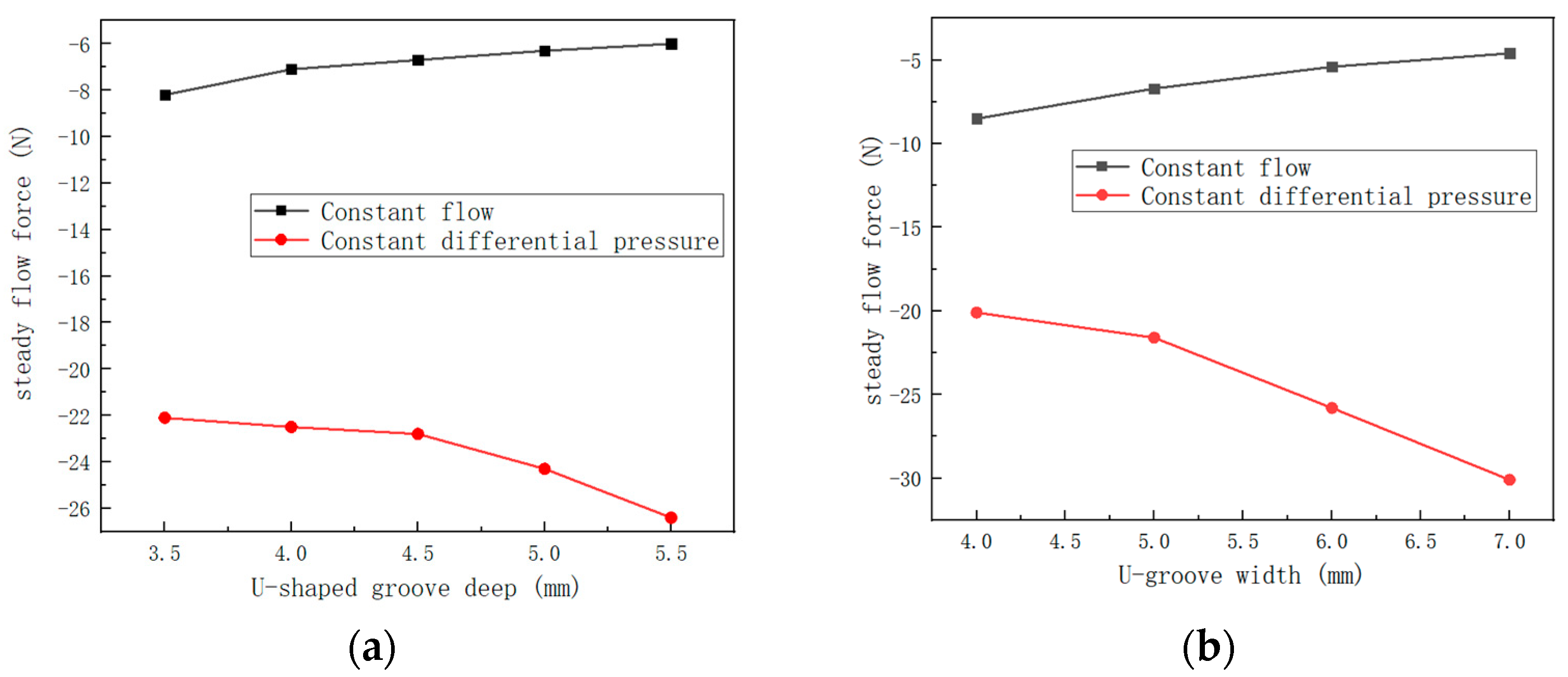
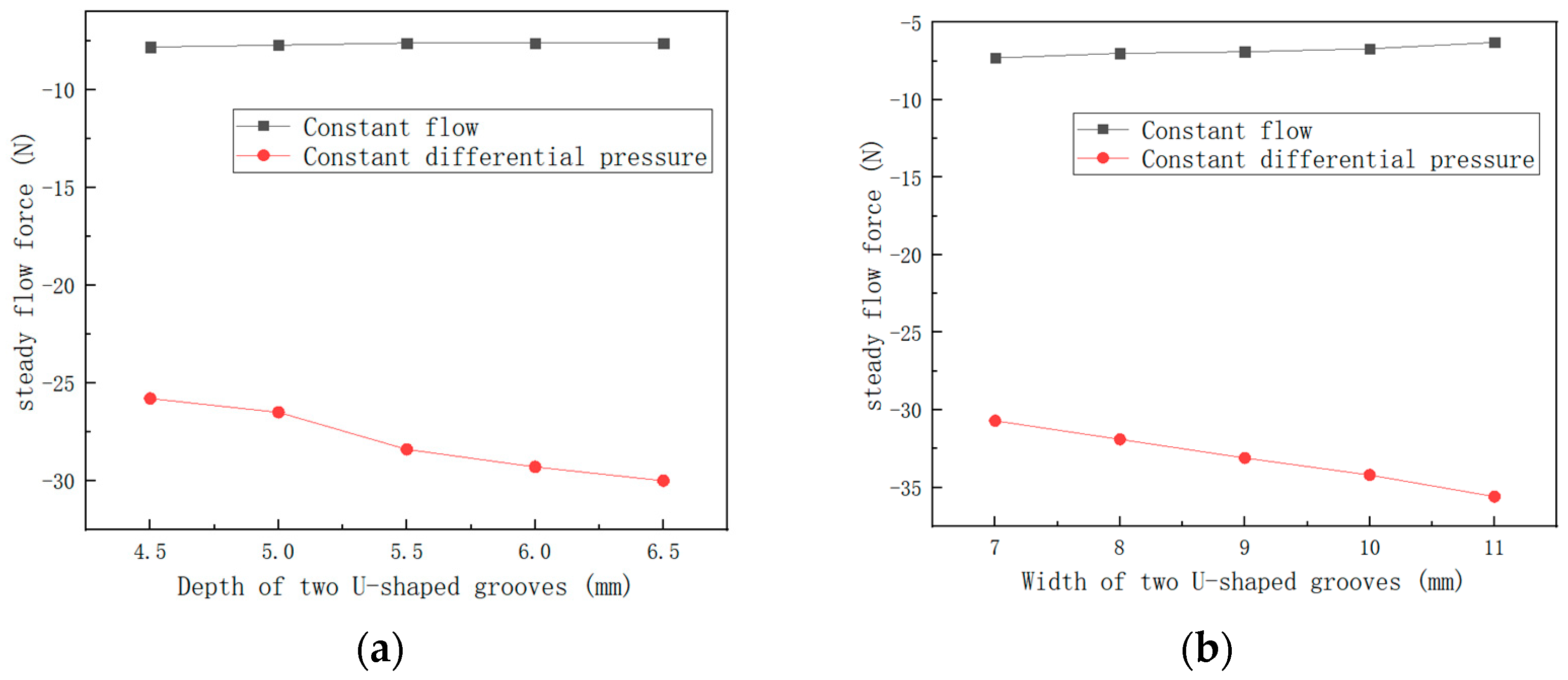
When a fluid flows into an asymmetric flow chamber and enters an annular orifice, the pressure and velocity of the fluid are unevenly distributed on the orifice, so the radial component of the flow force is not zero. As shown in Figure 9, the research results of Li et al. [75] indicated that under constant pressure difference conditions, the depth and width of U-shaped throttling grooves has an impact on the steady-state flow force of the system. Specifically, increasing the depth and width of the throttling grooves increases the hydraulic power of the system. Therefore, in order to reduce the flow force of the system under constant pressure difference conditions, the width and depth of U-shaped throttling grooves should be minimized as much as possible. Under constant flow conditions, the depth and width of U-shaped throttling grooves have opposite effects on the steady-state flow force of the system. Increasing the depth of throttling grooves can reduce the flow force of the system, while increasing their width can also reduce the flow force of the system. Therefore, under the condition of a constant flow rate and a constant pressure difference, the width and depth of U-shaped throttling grooves should be increased as much as possible to reduce the flow force of the system. As shown in Figure 10a,b [75], the effect of dual U-shaped throttling slots on steady-state flow force is basically similar to that of a single U-shaped throttling slot. Based on the influence of U-shaped throttling grooves on steady-state flow force mentioned above, Li et al. analyzed the influence of the parameters of P-B U-shaped throttling grooves on flow force through orthogonal experiments. They used range analysis to compare and analyze the influence of the four parameters of the double U-shaped grooves at P-B ports, namely, the depth, width, depth, and width, on the steady-state flow force. Finally, based on ensuring that the maximum flow area does not change more than 5%, the U-shaped groove parameters of P-B ports were optimized and the steady-state hydrodynamic peak value during the spool movement was reduced by 11.9%.

4.1.2. Structural Design of Valve Sleeves

Zhang [76] selected three types of spool valve and valve sleeve structures for hydraulic comparison. The first type was conventional spool valve and valve sleeve structures. The second type adopted a conventional structure for the valve sleeve, and the concave shoulder of the spool valve is processed into a conical surface. The third method was to add a return groove to the valve sleeve, and the concave shoulder of the spool valve was processed into a conical surface. The three structures are shown in Figure 11, Figure 12 and Figure 13. The CFD simulation results showed that under the same valve opening, the jet angle of structure 3 was the highest, followed by structures 2 and 1 for the three types of proportional valves. The maximum relative error of structure 2 relative to structure 1 was 1.49%, and the maximum relative error of structure 3 relative to structure 1 was 2.31%. The average jet angle of the three structures was 64.61°, and the maximum relative error was 1.92%. The use of a concave shoulder conical surface of the proportional spool valve and a valve sleeve reflux groove structure can not only increase the jet angle, but also generate a reverse opening flow force to compensate for the flow force on the proportional spool valve, thereby reducing the impact of the comparison spool valve. This indicates that changing the structure of the hydraulic valve chamber has a significant impact on the jet angle and also affects the magnitude of the flow force.
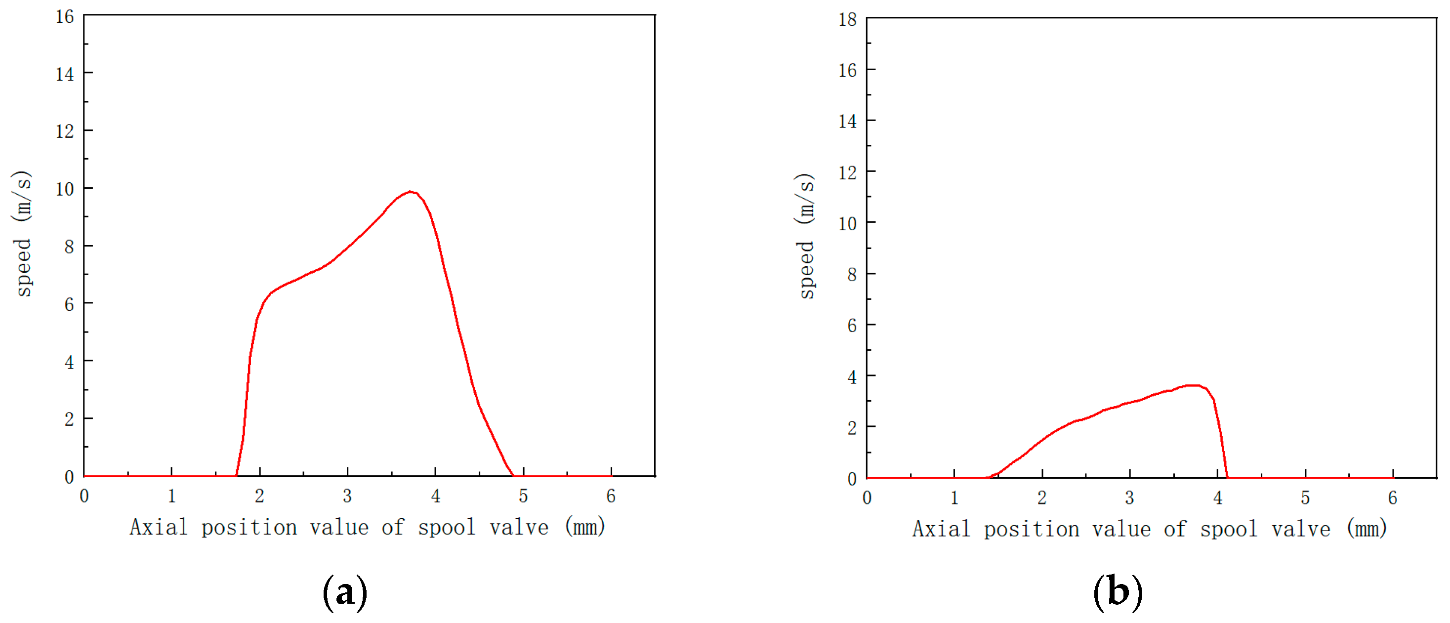
Due to the optimization of the geometric structure of a spool valve and not reducing the flow force at the outlet edge, Niko Herakovič [77] designed the valve as a sliding spool sleeve configuration. The main function of the valve sleeve was to supply the oil flowing out of the outer circumferential groove to the sliding spool valve and to keep it away from the sliding spool valve under the determined control edge geometry. The experimental results showed that the measurement results of the flow force characteristics of the spool valve using an improved valve sleeve were completely different but were very ideal flow force characteristics compared to the old structure. The sleeve avoided strong overcompensation, while the maximum value of flow force did not significantly increase. Song [78], Duan [79], and Wu et al. [80] proposed a new method to improve the valve sleeve structure, which uses an inclined hole valve sleeve, as shown in Figure 14. Compared to traditional valve sleeves, the biggest difference of this type of valve sleeve is that there is a series of radial inclined holes symmetrically arranged along the circumference above it. When the liquid flows into the inlet indicated by the arrow, it passes through the inclined hole at a certain speed ω1 and enters the valve chamber, and then at speed ω2, it flows out from the throttle port. According to the momentum theorem, the steady-state flow force on the spool valve is related to the difference in axial flow velocity of the fluid at the inlet and outlet of the valve chamber. Therefore, by changing the structural size or arrangement of the valve channel, the axial velocity difference between the inlet and outlet of the valve chamber can be reduced, thereby reducing the flow force on the spool valve. As shown in Figure 15 [79], the axial velocity of the fluid entering the valve chamber varies. For spool valves with radial inclined holes, the maximum axial velocity entering the valve chamber can reach 10 m/s, while for general spool valves, the maximum axial velocity entering the valve chamber is 4 m/s. In addition, the maximum axial velocity at the outlet is 22 m/s. Therefore, it can be seen that in spool valves with inclined holes in the valve sleeve, the axial velocity difference is 12 m/s, while in general, spool valves produce an axial velocity difference of 18 m/s. Under the same flow rate and density conditions, the steady-state flow force generated by a spool valve with a radial inclined hole is much smaller than that generated by a general spool valve.

4.1.3. Design of Flow Channels for Valve Bodies

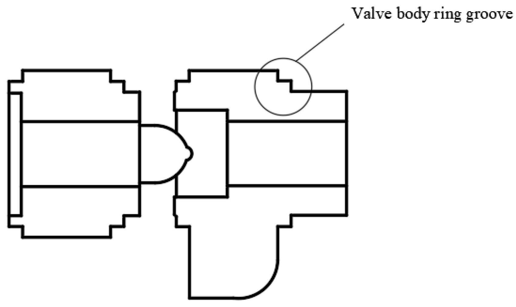
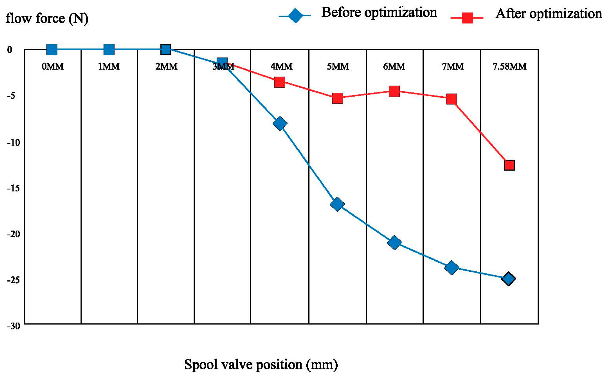
The axial velocity difference at the inlet and outlet of the valve chamber is caused by the inertia force of liquid flow when the valve is opened or closed and the influence of the valve structure. This speed difference can cause the spool valve to be subjected to unstable flow forces, thereby affecting the performance and lifespan of said valve. In order to reduce the effect of this flow force, certain measures need to be taken. For example, the axial velocity difference at the inlet and outlet of the valve chamber can be minimized by changing the structural size or arrangement of the valve passage. Niko Herakovič [81] optimized the design of spool valves and valve casing to reduce the steady-state flow force in the axial direction. According to CFD simulation, the optimal inlet angle of spool valves is 30 degrees, with the minimum flow force. Wang and his team [82] conducted flow analysis and comparison of liquid in different channel arrangements within spool valves. They elaborated on the relationship between the steady-state flow force of a spool valve and the layout of the flow channel, and they reduced the steady-state flow force by adjusting the layout of the flow channel, thereby significantly improving the steady-state performance of said valve. Song [83] added a corresponding circular groove structure to the valve body of the oil inlet chamber and the P chamber, so that the left and right circular grooves of the valve body are symmetrically distributed, in order to reduce flow force and optimize the operating performance of multi-way valves. As shown in Figure 16, circular grooves with a width of 1.5 mm were added on the left and right sides. As shown in Figure 17 [83], the optimized structure of the valve body causes a significant decrease in the flow force value of spool valves, with a significant decrease in the peak flow force. By changing the annular groove of the valve body, the flow force can be effectively reduced. As shown in Figure 18 [28], Lisowski reduced the steady-state flow force by adding flow channels in the valve body, namely, parallel flow channels and compensating flow channels. By comparing the CFD analysis of the axial force between the standard design and the new innovative design, it was found that the pressure in the flow channel of the innovative design is uniform, and the flow force at maximum flow rate is reduced by approximately 50%, indicating an increase in the operating limit of the directional control valve.

4.2. Radial Flow Force

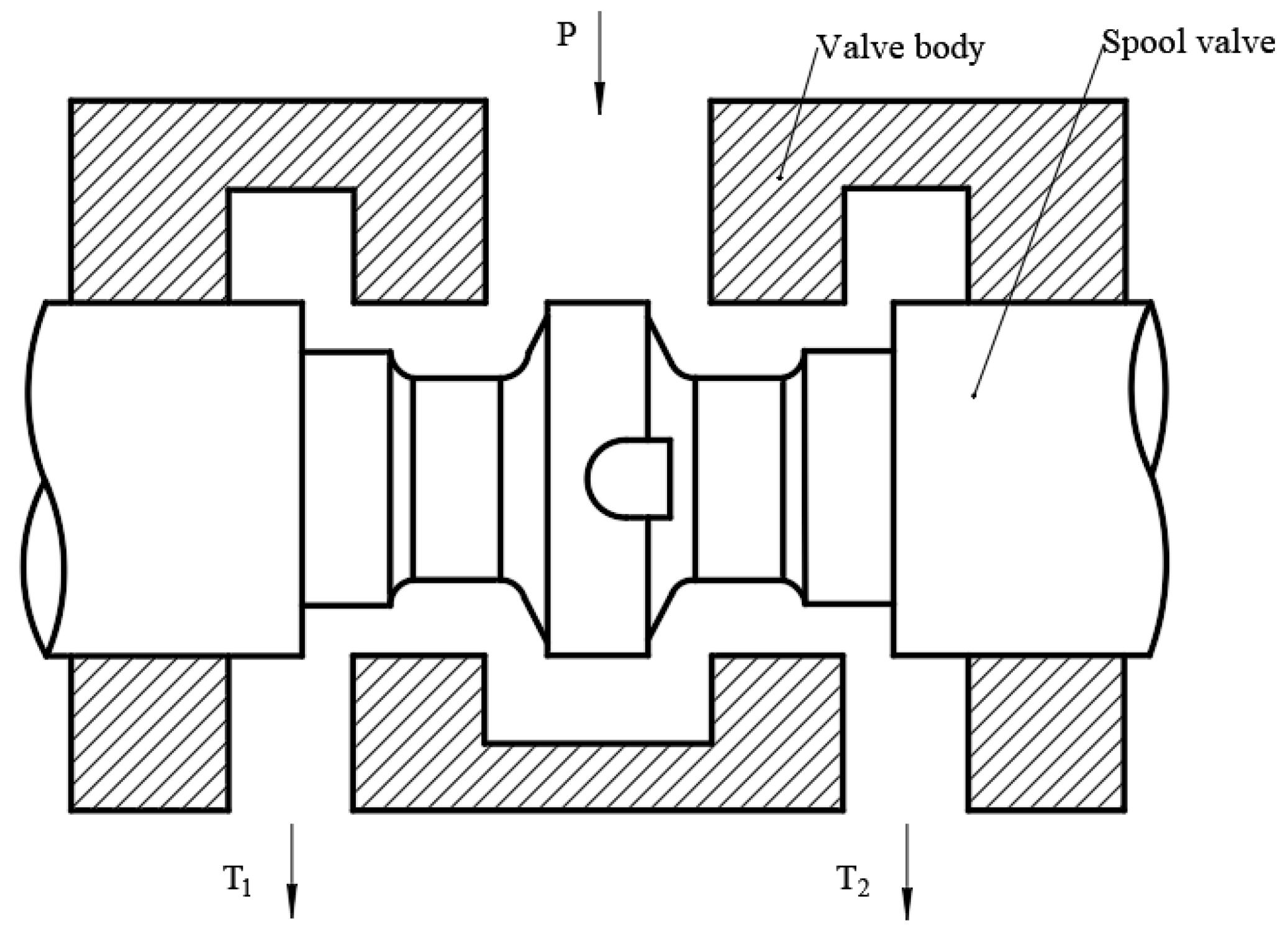
As shown in Figure 19 [84], Lu studied the radial flow force of a 2D servo spool valve with five asymmetric oil channels in the casing. The results indicated that the distribution of radial flow force is influenced by the inlet flow velocity and the opening of the orifice. The amplitude of radial flow force increases linearly with the square of the inlet flow velocity and is inversely proportional to the size of the opening. The net radial force acting on the spool valve does not cancel out each other, but instead increases with the increase in inlet flow rate and orifice size. Hong [85] compared the radial flow forces on spiral groove spool valves and typical groove spool valves. Since the spiral groove is a continuous groove, a spool valve with a spiral groove can not only provide better performance to alleviate the asymmetric pressure distribution in the radial clearance, but also effectively alleviate the uneven pressure distribution around spool valves. When a spool valve moves from the low-pressure zone to the high-pressure zone, the volumetric flow rate of a spool valve with a typical groove is lower than that of a spiral groove. However, when the spool valve moves from the high-pressure zone to the low-pressure zone, the volumetric flow rate of a spool valve with spiral grooves is lower than that of the typical groove. Lu [86] found that when the flow rate is the same, the torque generated by the axial and circumferential components of steady-state hydraulic force in the spiral valve port decreases with the increase in pilot valve port opening. When the valve opening is constant, as the inlet flow rate increases, the jet angle remains unchanged and the axial and circumferential hydraulic torque gradually increase. This discovery provides important guidance for further studying the hydrodynamic characteristics of spiral valve ports, and it also helps to optimize the design and use of spiral valve ports.
Due to limitations in processing conditions, there are certain geometric errors in spool valves and the valve body of hydraulic valves. In this case, the hydraulic oil entering the assembly gap of the spool valve generates radial flow force. The irregular distribution of radial flow force can lead to the overall eccentricity and inclination of spool valves, as well as generate hydraulic clamping force, thereby affecting the working performance of hydraulic spool valves. Zeng [87] studied the effect of different types of equalizing grooves on the hydraulic clamping force on spool valves. Through research, it can be concluded that the number of equalizing grooves is the main influencing factor of hydraulic clamping force. The shape and size of the equalizing grooves have little effect. To ensure the normal operation of hydraulic valves and avoid jamming, spool valves should have at least three equalizing grooves.

4.3. Transient Flow Force

The direction of the transient flow force is opposite to the direction of liquid flow in the valve body. When the valve port is opened, if the direction of the transient flow force changes, it will cause the spool valve to oscillate. Oscillation of spool valves not only leads to deterioration in the dynamic characteristics of hydraulic valves, but also causes the sealing ring between a spool valve and the valve sleeve to fail, leading to a decrease in the safety of hydraulic valves. Li and his team [88] conducted mathematical analysis on a spool of the FAD1000 safety valve, using MATLAB/Simulink for mathematical modeling. Transient flow force is closely related to valve opening and valve geometry. The geometric shape of the valve port mainly includes parameters such as the radial clearance between a spool valve and the valve hole, the number of small outlet holes, and the diameter and length of the inner hole of a spool valve. By adjusting the geometric parameters of spool valves reasonably, the transient flow force can be effectively reduced and the performance of safety valves can be improved. Wang et al. [89] designed a directional spool valve with a convex platform and sink groove. In this paper, hydrodynamic analysis of the spherical spool valve was carried out by means of visual numerical analysis in the flow channel of a certain state during the dynamic opening process, and the pressure integral on the fluid grid was used to calculate the magnitude of the transient flow force acting on the spool valve, after which the formula for calculating the transient flow force was given. Transient flow force is related to the flow channel structure, and a reasonable spool valve and flow channel structure can effectively reduce the magnitude of transient flow force.
F = F r F 1 = P i   d A P j   d A = M P i A i N P j A j .
In the formula, Pi and Pj are the dynamic pressures on the fluid grids i and j; M and N refer to the number of grids on the fluid boundary corresponding to the left and right shoulder surfaces, respectively.
Zhang [90] established a hydraulic spool valve with a circular chamfer, which has certain guiding significance for how to avoid sudden changes in transient flow force and hydraulic impact, as well as improving the reliability and stability of spool valves.

5. Conclusions

The flow force inside spool valves is divided into steady-state flow force and radial flow force. Steady-state flow force, also known as Bernoulli force, is the reaction force that changes the direction of liquid flow into and out of the valve chamber to the spool valve. Its direction is always toward the direction that causes the spool valve to close, mainly affecting the working performance and control performance of said valve. Reducing the flow force of hydraulic spool valves is a very important issue for improving the performance of spool valves.
For the most influential axial steady-state flow force, most scholars adopt two methods: One is to increase or reduce the internal structure of hydraulic spool valves, such as adding convex platforms at a spool valve, adding flow channels in the valve body, and increasing the fillet of a spool valve. This method can significantly reduce the magnitude of axial flow force, but some structural changes can bring about problems with the strength and stability of spool valves or valve bodies, increase the uncertainty of the fit between said valves and valve bodies, increase the difficulty of production and manufacturing, and increase manufacturing costs. Another method is to reduce the flow force only by changing the structural parameters. This method does not change the structure of a hydraulic valve itself, but only adjusts some of its parameters, reducing manufacturing costs. However, the effect of reducing flow force is not as significant as in the previous method.
At present, most scholars believe that the radial flow force of a structurally symmetrical spool valve can be ignored, but the radial flow force and hydraulic clamping force are interrelated. Ignoring the radial flow force cannot accurately understand the actual performance of hydraulic spool valves. Adding continuous grooves on a spool valve can effectively reduce the radial flow force.
Transient flow force is often overlooked by scholars. It is often generated during the opening process of the valve port, with the direction opposite to the liquid flow direction, mainly affecting the speed of response of hydraulic spool valves. Reducing the transient flow force can be achieved by increasing chamfers, increasing the convex platform, and other methods.
The main research directions for hydraulic spool valve internal hydraulic power in the future are: (1) Design simpler and more effective structures to reduce steady-state and transient flow force. (2) Conduct more extensive research on radial steady-state and transient flow forces. (3) Adopt hydraulic compensation to reduce energy loss and operational costs.
This article reviewed the causes, influencing factors, and methods for reducing the flow force of hydraulic spool valves. The research on flow force in hydraulic spool valves conforms to the current trend of high precision and high stability in hydraulic systems, and points out the development direction for modern spool valve manufacturing enterprises.

Author Contributions

Conceptualization, R.L. and Y.S.; methodology, D.L.; software, D.L.; validation, Q.S.; formal analysis, Y.S.; investigation, P.Z.; resources, P.Z.; data curation, Y.S.; writing—original draft preparation, Y.S.; writing—review and editing, R.L.; visualization, Q.S.; supervision, X.W. and R.L.; project administration, X.W.; funding acquisition, X.W., Y.X. and J.L. All authors have read and agreed to the published version of the manuscript.

Funding

(1) Key R&D Plan of Shandong Province, China, grant number: 2020CXGC011005; (2) General Project of Shandong Natural Science Foundation, grant number: ZR2021ME116; (3) Major Innovation Project of Shandong Province, grant number: 2022CXGC020702; (4) Major Innovation Project of Shandong Province, grant number: 2021CXGC010812; (5) Key R&D Plan of Shandong Province, China, grant number: 2021CXGC010207; (6) Key R&D Plan of Shandong Province, China, grant number: 2020CXGC011004.

Data Availability Statement

Not applicable.

Acknowledgments

The authors would like to thank Ruichuan Li, for all of his support and guidance. They would also like to thank their colleagues for the care and help in their daily work.

Conflicts of Interest

The authors declare no conflict of interest.

References

  1. Altare, G.; Rundo, M.; Olivetti, M. 3D dynamic simulation of a flow force compensated pressure relief valve. In Proceedings of the ASME 2016 International Mechanical Engineering Congress and Exposition, Phoenix, AZ, USA, 11–17 November 2016. [Google Scholar]
  2. Wang, B.; Liu, H.; Hao, Y.X.; Quan, L.; Li, Y.W.; Zhao, B. Design and Analysis of a Flow-Control Valve With Controllable Pressure Compensation Capability for Mobile Machinery. IEEE Access 2021, 9, 98361–98368. [Google Scholar] [CrossRef]
  3. Lü, X.B.; Peng, J.H.; Li, S.J. Dynamic characteristics of the jet force on the flapper of the pilot stage in a flapper nozzle servo valve under the flow-solid interaction. J. Beijing Inst. Technol. 2020, 29, 445–455. [Google Scholar]
  4. Amirante, R.; Del, V.G.; Lippolis, A. Evaluation of the flow forces on an open centre directional control valve by means of a computational fluid dynamic analysis. Energy Convers. Manag. 2006, 47, 1748–1760. [Google Scholar] [CrossRef]
  5. Lee, G.S.; Sung, H.J.; Kim, H.C.; Lee, H.W. Flow force analysis of a variable force solenoid valve for automatic transmissions. J. Fluids Eng. 2010, 132, 031103. [Google Scholar] [CrossRef]
  6. Fan, Y.L.; Lei, Y.; Zhang, J.W.; Wang, J.; Li, Z. Flow Force of Pressure Independent Control Valve with Different Valve Core Structural. J. Phys. Conf. Ser. 2020, 1634, 012149. [Google Scholar] [CrossRef]
  7. Xue, M.; Lin, H.L.; Zheng, X.L. Influence and Improvement of Hydraulic Power on Spool Valve Reversing. In Proceedings of the 2021 International Conference on Power Grid System and Green Energy (PGSGE 2021), Wuhan, China, 26–28 March 2021; Volume 252. [Google Scholar]
  8. Finesso, R.; Rundo, M. Numerical and experimental investigation on a conical poppet relief valve with flow force compensation. Int. J. Fluid Power 2017, 18, 111–122. [Google Scholar] [CrossRef]
  9. Simic, M.; Herakovic, N. Reduction of the flow forces in a small hydraulic seat valve as alternative approach to improve the valve characteristics. Energy Convers. Manag. 2015, 89, 708–718. [Google Scholar] [CrossRef]
  10. Feng, G.C. Analysis and Calculation of the Orifice Area of Spool with L+U Type Notches. Mach. Tool Hydraul. 2018, 46, 62+63–65. [Google Scholar]
  11. Rannow, M.B.; Li, P.Y. Soft switching approach to reducing transition losses in an on/off hydraulic valve. In Proceedings of the ASME 2009 Dynamic Systems and Control Conference, Hollywood, CA, USA, 12–14 October 2009; Volume 48920, pp. 613–620. [Google Scholar]
  12. Tan, L.; Xie, H.; Chen, H.; Yang, H. Structure optimization of conical spool and flow force compensation in a diverged flow cartridge proportional valve. Flow Meas. Instrum. 2019, 66, 170–181. [Google Scholar] [CrossRef]
  13. Amirante, R.; Andrea, C.L.; Tamburrano, P. The importance of a full 3D fluid dynamic analysis to evaluate the flow forces in a hydraulic directional proportional valve. Eng. Comput. 2014, 31, 898–922. [Google Scholar] [CrossRef]
  14. Jiang, Y.; Xu, J.M. Simulation research on dynamic performance of cartridge two position four way directional valve. Mach. Tool Hydraul. 2021, 49, 133–135. [Google Scholar]
  15. He, X.L. Analysis of Internal Energy Consumption Mechanism of Single Section U-Groove Spool Valve. Master’s Thesis, Lanzhou University of Technology, Lanzhou, China, 2017. [Google Scholar]
  16. Zhang, Y.J. Compensation of Steady State Flow Forces in Slide Valves. Heilongjiang Keji Daxue Xuebao 2018, 18, 51–55. [Google Scholar]
  17. Lu, J.M.; Zhou, D.J.; Feng, Z.J.; Liu, H. Calculation and Analysis of Flow Area and Hydraulic Diameter for Typical Hydraulic Notches. Hydraul. Pneum. Seals 2016, 36, 44–46. [Google Scholar]
  18. Zhang, H.P. Correction for Some Wrong Opinions about Flow Forces. Hydraul. Pneum. Seals 2010, 30, 10–15. [Google Scholar]
  19. Hu, Z.L. Study on Characteristics and Optimization of Hydraulic Solenoid Valve. Master’s Thesis, Shanghai Jiaotong University, Shanghai, China, 2015. [Google Scholar]
  20. Wang, H.; Jia, W.H.; Zhu, Y.R.; Sun, C.L.; Wang, C. Dynamic Characteristics and Stability Analysis of Poppet Relief Valve. Mach. Tool Hydraul. 2019, 47, 144–147. [Google Scholar]
  21. Shimizu, F.; Tanaka, K. Generation Mechanism of Flow Force Acting on Spool Valve. JFPS Int. J. Fluid Power Syst. 2022, 15, 71–77. [Google Scholar] [CrossRef]
  22. Amirante, R.; Moscatelli, P.G.; Catalano, L.A. Evaluation of the flow forces on a direct (single stage) proportional valve by means of a computational fluid dynamic analysis. Energy Convers. Manag. 2007, 48, 942–953. [Google Scholar] [CrossRef]
  23. Amirante, R.; Catalano, L.A.; Poloni, C.; Tamburrano, P. Fluid-dynamic design optimization of hydraulic proportional directional valves. Eng. Optim. 2014, 46, 1295–1314. [Google Scholar] [CrossRef]
  24. Amirante, R.; Distaso, E.; Tamburrano, P. Sliding spool design for reducing the actuation forces in direct operated proportional directional valves: Experimental validation. Energy Convers. Manag. 2016, 119, 399–410. [Google Scholar] [CrossRef]
  25. Li, S.N.; Ge, S.H.; Wang, Y.M.; Shi, W.X. Study and Application of a New Method for the Compensation of Steady State Flow Forces in Slide Valves. J. Xi’an Jiaotong Univ. 1986, 5, 63–70. [Google Scholar]
  26. Tang, Z.Y.; Cao, B.G.; Shi, W.X. Discussion on Steady State Hydraulic Power Compensation Method for Hydraulic Control Valves—Valve Sleeve Motion Method. Mach. Tool Hydraul. 1995, 2, 91–95. [Google Scholar]
  27. Li, Z.T. Design and Optimization Study of 6 Diameter Intrinsically Safe Directional Solenoid Valve. Master’s Thesis, Zhejiang University, Zhejiang, China, 2022. [Google Scholar]
  28. Lisowski, E.; Czyżycki, W.; Rajda, J. Three dimensional CFD analysis and experimental test of flow force acting on the spool of solenoid operated directional control valve. Energy Convers. Manag. 2013, 70, 220–229. [Google Scholar] [CrossRef]
  29. Huang, H.; Li, X.; Sun, Z.W. Steady hydrodynamic force analysis of non-circular opening hydraulic spool valve. Appl. Mech. Mater. 2012, 220, 1657–1660. [Google Scholar] [CrossRef]
  30. Liu, J.; Li, R.; Ding, X.; Liu, Q. Flow force research and structure improvement of cartridge valve core based on CFD method. Heliyon 2022, 8, e11700. [Google Scholar] [CrossRef]
  31. Borghi, M.; Milani, M.; Paoluzzi, R. Stationary axial flow force analysis on compensated spool valves. Int. J. Fluid Power 2000, 1, 17–25. [Google Scholar] [CrossRef]
  32. Pan, X.D.; Wang, G.L.; Lu, Z.S. Flow field simulation and a flow model of servo-valve spool valve orifice. Energy Convers. Manag. 2011, 52, 3249–3256. [Google Scholar] [CrossRef]
  33. Shi, W.X.; Li, S.N.; Ge, S.H. A new technique for steady state flow force compensation in spool valves. Proc. Inst. Mech. Eng. Part E 1990, 204, 7–14. [Google Scholar]
  34. Wang, X.K. Radial Steady—State Flow Force of Hydraulic Directional Valve. Chin. Hydraul. Pneum. 2020, 12, 114–117. [Google Scholar]
  35. Zheng, C.S.; Fan, J.H.; Du, Q.; You, Y.S.; Liu, Z.Q.; Gao, Z. Study on Characteristics of Flow Field and Steady Flow Force of Hydraulic Spool Valve Based on CFD. Mach. Tool Hydraul. 2017, 45, 145–151. [Google Scholar]
  36. Lu, Q.Q.; Wan, J.; Li, S. Research on Radial Forces for Hydraulic Slide Valves Caused by Bernoulli Effect. China Mech. Eng. 2017, 28, 2332–2338. [Google Scholar]
  37. Chen, Q.-P.; Ji, H.; Xing, H.-H.; Zhao, H.-K. Experimental study on thermal deformation and clamping force characteristics of hydraulic spool valve. Eng. Fail. Anal. 2021, 129, 105698. [Google Scholar] [CrossRef]
  38. Chen, Q.P. Experimental Study on the Micro Mechanism of Thermal-Particle Coupling Clamping of Hydraulic Spool Valve. Doctoral Thesis, Lanzhou University of Technology, Lanzhou, China, 2021. [Google Scholar]
  39. Merritt, H.E. Hydraulic Control Systems; Wiley: New York, NY, USA, 1967; pp. 76–118. [Google Scholar]
  40. Nakada, T.; Ikebe, Y. Measurement of the unsteady axial flow force on a spool valve. In Proceedings of the IFAC Symposium, Warsaw, Poland, 20–23 May 1980; pp. 193–198. [Google Scholar]
  41. Vescovo, D.G.; Lippolis, A. A review analysis of unsteady forces in hydraulic valves. Int. J. Fluid Power 2006, 7, 29–39. [Google Scholar] [CrossRef]
  42. Manring, N.D.; Zhang, S. Pressure Transient Flow Forces for Hydraulic Spool Valves. J. Dyn. Syst. Meas. Control 2012, 134, 034501. [Google Scholar] [CrossRef]
  43. Guo, X.E.; Zhao, J.L. The influence of transient hydraulic force on the safe operation of electromagnetic directional valves in hydraulic systems. Min. Saf. Environ. Prot. 2002, 5, 27–29. [Google Scholar]
  44. Yin, Y.C.; Gao, Y. The influence of transient hydraulic force on the safe operation of electromagnetic directional valve. Coal 2004, 3, 50–52. [Google Scholar]
  45. Lu, L.; Wang, J.; Ling, Y.Y.; Li, H.X. Numerical Simulation Analysis of Vortex Cavitation in Spool Valve with V-shape Notch. Chin. Hydraul. Pneum. 2022, 46, 110–118. [Google Scholar]
  46. Han, M.X.; Liu, Y.S.; Wu, D.F.; Tan, H.J. Flow force reduction in large flow cartridge valve by optimizing geometric parameters of orifice. J. Huazhong Univ. Sci. Technol. 2018, 46, 65–68. [Google Scholar]
  47. Aung, N.Z.; Li, S. A numerical study of cavitation phenomenon in a flapper-nozzle pilot stage of an electrohydraulic servo-valve with an innovative flapper shape. Energy Convers. Manag. 2014, 77, 31–39. [Google Scholar] [CrossRef]
  48. Chen, Q.; Stoffel, B. CFD simulation of a hydraulic servo valve with turbulent flow and cavitation. In Proceedings of the ASME/JSME 2004 Pressure Vessels and Piping Conference, San Diego, CA, USA, 25–29 July 2004; Volume 46865, pp. 197–203. [Google Scholar]
  49. Ma, L.; Yan, H.; Ren, Y.; Li, L.; Cai, C. Numerical Investigation of Flow Force and Cavitation Phenomenon in the Pilot Stage of Electrical-Hydraulic Servo Valve under Temperature Shock. Machines 2022, 10, 423. [Google Scholar] [CrossRef]
  50. Aung, N.Z.; Peng, J.H.; Li, S.J. Reducing the steady flow force acting on the spool by using a simple jet-guiding groove. In Proceedings of the IEEE 2015 International Conference on Fluid Power and Mechatronics (FPM), Harbin, China, 5–7 August 2015; pp. 289–294. [Google Scholar]
  51. Bai, J.; Zhao, B.; Hao, Y.X.; Wang, B.; Liu, H. Hydrodynamic compensation method of proportional valve based on valve spool structure optimization. J. Mech. Electr. Eng. 2021, 38, 1444–1450. [Google Scholar]
  52. Zhang, Z.H.; Su, Q.; Li, H.B.; Fang, Z.F.; Chen, D.D.; Wei, Y.H. Optimized Design of Diversion Structure for Low Hydraulic Valve Core of Proportional Servo Valve. Flight Control Detect. 2022, 5, 8–15. [Google Scholar]
  53. Qu, D.H.; Zhou, Y.S.; Luo, W.; Liu, Y.F.; Fu, B. Influences of Fit Clearances on Steady-state Fluid Forces of Relief Valves. China Mech. Eng. 2018, 29, 893–899. [Google Scholar]
  54. Shi, J.Y.; Fan, F.H.; Zhang, K.C.; Li, H. Simulation Analysis of Steady Flow Force for Hydraulic Spool Valve Double Triangle Slot Valve Port Based on CFD. Hydraul. Pneum. Seals 2022, 42, 36–38. [Google Scholar]
  55. Gao, H.; Li, B.; Yang, G. Study on the influence of flow force on a large flowrate directional control valve. IFAC Proc. Vol. 2013, 46, 469–477. [Google Scholar] [CrossRef]
  56. Zhang, H.; Guan, T.Y.; Zhou, S.C.; Zhang, R.X.; Zhang, R.Z. Steady Flow Force Simulation Analysis of Large Flow Multi-way Valve. Chin. Hydraul. Pneum. 2020, 7, 132–137. [Google Scholar]
  57. Deng, B.; Qiu, F.C.; Wu, W.H.; Ke, J.; Wang, G.Z. Influence of Steady-state Flow Force on Operating Force of Multi-way Valve Spool. Mach. Tool Hydraul. 2017, 45, 68–71. [Google Scholar]
  58. Yang, T.; Nie, W.L.; Xia, S.Q. Steady-state Hydrodynamic Force Analysis on Combination Rectangular Notch Orifice of Multiple Directional Valve. Hydraul. Pneum. Seals 2016, 36, 34–37. [Google Scholar]
  59. Ji, H.; Fu, X.; Yang, H.Y. Study on Steady Flow Force of Non-circular Opeing Spool Valve. J. Mech. Eng. 2003, 6, 13–17. [Google Scholar] [CrossRef]
  60. Ye, Y.; Yin, C.-B.; Li, X.-D.; Zhou, W.-J.; Yuan, F.-F. Effects of groove shape of notch on the flow characteristics of spool valve. Energy Convers. Manag. 2014, 86, 1091–1101. [Google Scholar] [CrossRef]
  61. Yao, J.Y. Simulation of Spool Valve with Notches Based on Fluent. Master’s Thesis, Yanshan University, Qinhuangdao, China, 2014. [Google Scholar]
  62. Frosina, E.; Marinaro, G.; Senatore, A.; Pavanetto, M. Numerical and experimental investigation for the design of a directional spool valve. Energy Procedia 2018, 148, 274–280. [Google Scholar] [CrossRef]
  63. Qu, D.; Zhou, Y.; Liu, Y.; Luo, W.; Zhang, F. Steady flow force compensation and test research on electrohydraulic proportional relief valve. IEEE Access 2019, 7, 48087–48097. [Google Scholar] [CrossRef]
  64. Chen, Q.P. Characteristic Study and Modification Method for Steady-State Flow Force of Open Center Multi-Way Valve. Master’s Thesis, Lanzhou University of Technology, Lanzhou, China, 2017. [Google Scholar]
  65. Zhang, S.F.; Zhang, S.; Wang, Q.; He, X.H.; Xu, L. Transient Properties of Hydraulic Operated Directional Valve Based on Fluid-structure Interaction. J. Ordnance Equip. Eng. 2017, 38, 151–155. [Google Scholar]
  66. Guo, B.; Xie, N.; Guo, J.J.; Liu, J. Research on Flow Force of the Spool Valve and Structure Analysis. Hydraul. Pneum. Seals 2012, 32, 11–15. [Google Scholar]
  67. Zhou, S.C.; Zhang, H.; Lu, Y.; Zhan, D.Y.; Zhang, R.X.; Zhang, R.Z. Multi-way Valve Structure Design and Improvement. Chin. Hydraul. Pneum. 2022, 46, 38–44. [Google Scholar]
  68. Chen, Q.P.; Ji, H.; Zhu, Y.; Yang, X. Proposal for optimization of spool valve flow force based on the MATLAB-AMESim-FLUENT joint simulation method. IEEE Access 2018, 6, 33148–33158. [Google Scholar]
  69. Gui, S.; Zhang, S.; Fu, B.; Ling, M. Fluid-dynamic analysis and multi-objective design optimization of piezoelectric servo valves. Flow Meas. Instrum. 2022, 85, 102157. [Google Scholar] [CrossRef]
  70. Gui, S.Y.; Zhang, X.; Zhang, S.S.; Fu, B.; Ling, M.X. Dynamic Characteristic Analysis and Multi-objective Optimization of Hydraulic Servo Valve Spool. J. Xi’an Jiaotong Univ. 2022, 56, 33–45. [Google Scholar]
  71. Lisowski, E.; Filo, G.; Rajda, J. Analysis of flow forces in the initial phase of throttle gap opening in a proportional control valve. Flow Meas. Instrum. 2018, 59, 157–167. [Google Scholar] [CrossRef]
  72. Lisowski, E.; Filo, G. Analysis of a proportional control valve flow coefficient with the usage of a CFD method. Flow Meas. Instrum. 2017, 53, 269–278. [Google Scholar] [CrossRef]
  73. Dong, Y.K.; Fu, L.D. Structural Simulation Analysis of Spool Valve with V-shaped Throttle Groove. J. Wuhan Univ. Sci. Technol. 2021, 44, 119–124. [Google Scholar]
  74. Guan, T.Y. Optimal Design of Multi-Way Valve Notches Based on Steady-State Flow Force Analysis. Master’s Thesis, Dalian University of Technology, Dalian, China, 2020. [Google Scholar]
  75. Li, Z.C. The Steady Flow Force Optimization of Truck Cranes Multi-Way Valve Based on CFD. Master’s Thesis, Dalian University of Technology, Dalian, China, 2020. [Google Scholar]
  76. Zhang, G.; Huang, J.; Qiu, R. Evaluation of the Flow Forces on an Electro-hydraulic Proportional Valve Based on CFD Analysis. J. Mach. Des. 2010, 27, 93–96. [Google Scholar]
  77. Herakovič, N. Flow-force analysis in a hydraulic sliding-spool valve. Stroj. Časopis Teor. Praksu Stroj. 2009, 51, 555–564. [Google Scholar]
  78. Song, Z.L.; Zhang, X.J.; Liang, Y.W.; Zhang, J. Flow Field Characteristics and Optimization of Non-full Circumference Open Spool Valve. J. Mech. Electr. Eng. 2022, 39, 317–323. [Google Scholar]
  79. Duan, S.S.; Yao, P.X.; Zhang, H. Steady-state Fluid Force of Spool Valve and Its Compensation Method. Fluid Power Transm. Control 2010, 3, 27–30. [Google Scholar]
  80. Wu, D.; Wang, X.; Ma, Y.; Wang, J.; Tang, M.; Liu, Y. Research on the dynamic characteristics of water hydraulic servo valves considering the influence of steady flow force. Flow Meas. Instrum. 2021, 80, 101966. [Google Scholar] [CrossRef]
  81. Herakovič, N.; Duhovnik, J.; Šimic, M. CFD simulation of flow force reduction in hydraulic valves. Tech. Gaz. 2015, 22, 453–463. [Google Scholar] [CrossRef] [Green Version]
  82. Wang, L.X.; Zhang, M.C.; Fang, Z.H. The Influence of Valve Inner Passage Arrangement on Hydraulic Power. Mach. Tool Hydraul. 2000, 6, 27–28. [Google Scholar]
  83. Song, B.S. Research on Valve Port Characteristics and Hydraulic Force of Load Sensitive Multi-Way Valve. Master’s Thesis, Dalian University of Technology, Dalian, China, 2019. [Google Scholar]
  84. Lu, Q.; Tiainen, J.; Kiani-Oshtorjani, M.; Ruan, J. Radial flow force at the annular orifice of a two-dimensional hydraulic servo valve. IEEE Access 2020, 8, 207938–207946. [Google Scholar] [CrossRef]
  85. Hong, S.H.; Kim, K.W. A new type groove for hydraulic spool valve. Tribol. Int. 2016, 103, 629–640. [Google Scholar] [CrossRef]
  86. Lu, Q.Q.; Ruan, J.; Li, S. Study on Steady-state Flow Force of Pilot Helical Orifice of 2D Servo Valve. Fluid Mach. 2019, 47, 25–30+47. [Google Scholar]
  87. Zeng, Q.L.; Cui, J.; Zhao, W.M. Simulation analysis for hydraulic clamping force of bidirectional hydraulic lock’valve spool based on Fluent. Adv. Mater. Res. 2012, 542, 1091–1095. [Google Scholar] [CrossRef]
  88. Li, G.Q.; Zhu, Y.Q.; Gao, Y.J.; Guo, B.J. Transient Flow Force Analysis of High-pressure Large-flow Safety Valve for Hydraulic Powered Support. Chin. Hydraul. Pneum. 2014, 7, 7–9+14. [Google Scholar]
  89. Wang, A.L.; Wu, X.F.; Zhou, C.L.; Ma, B. Multidisciplinary Optimization of a Hydraulic Slide Valve Based on CFD. J. Shanghai Jiaotong Univ. 2010, 44, 1767–1772. [Google Scholar]
  90. Zhang, S.; He, X.H.; Wang, Q.; Wang, X.W. Transient Properties of the Hydraulic Spool Valve Based on CFD. Equip. Manuf. Technol. 2016, 12, 28–30+40. [Google Scholar]
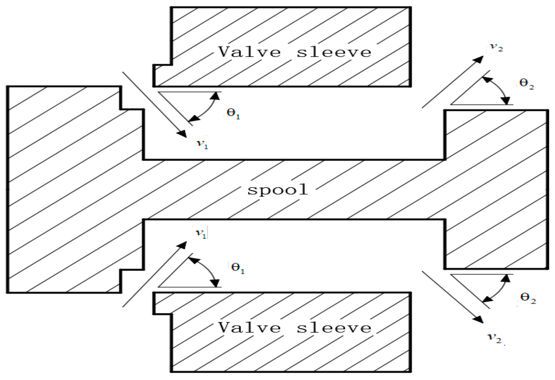
Figure 1. Steady-state hydrodynamic model of a slide valve; v1 and v2 are the inflow and outflow velocities, respectively; θ1 and θ2 are the jet angles at the inlet and outlet.
Processes 11 02183 g001
Figure 2. Traditional spool valve structure and optimized spool valve structure; θ1 and θ2 are the jet angles at the inlet and outlet. (a) Traditional solutions. (b) Innovative solutions.
Processes 11 02183 g002
Figure 3. Annular convex platform.
Processes 11 02183 g003
Figure 4. Circular step structure.
Processes 11 02183 g004
Figure 5. Structural optimization of a spool valve.
Processes 11 02183 g005
Figure 6. Optimization of the control room.
Processes 11 02183 g006
Figure 7. Calculation of the axial steady-state flow force acting on the main spool valve using CFD [69].
Processes 11 02183 g007
Figure 8. Experimental spool valve; 1, 2, 3, and 4—working edge.
Processes 11 02183 g008
Figure 9. Effect of a single U-shaped throttling groove on the steady-state flow force [75]. (a) The influence of throttling groove depth on flow force. (b) The influence of the width of the throttling groove on the flow force.
Processes 11 02183 g009
Figure 10. Effect of two U-shaped throttling grooves on the steady-state flow force [75]. (a) The influence of throttling groove depth on flow force. (b) The influence of the width of the throttling groove on the flow force.
Processes 11 02183 g010
Figure 11. General structure.
Processes 11 02183 g011
Figure 12. Conventional valve sleeve, with the spool valve machined into a conical surface.
Processes 11 02183 g012
Figure 13. Adding a return groove to the valve sleeve and machining the spool valve into a conical surface.
Processes 11 02183 g013
Figure 14. Schematic diagram of the valve sleeve inclined hole method.
Processes 11 02183 g014
Figure 15. Axial component of the slide valve inlet velocity [79]. (a) The axial component of the speed at the inlet of the valve sleeve opening. (b) Axial component of ordinary spool valve inlet velocity.
Processes 11 02183 g015
Figure 16. Modified flow channel model.
Processes 11 02183 g016
Figure 17. Flow force curve of the main valve port [83].
Processes 11 02183 g017
Figure 18. Pressure distribution of additional channels: 1—standard channel, 2—parallel channel, and 3—compensation channel [28].
Processes 11 02183 g018
Figure 19. 3D model of a 2D servo valve, where A and B are the working ports, P is the inlet port, and T is the return port [84].
Processes 11 02183 g019
Table 1. Table of the improvement of circular convexes with different diameters [67].
Ring Boss Diameter/mmMaximum Flow Loss/%2.1 mm Improvement Progress/%4 mm Improvement Progress/%
130.424.47.2
145.740.727.8
1510.044.032.2
1615.645.344.1
1722.638.755.1
Table 2. The size of the optimized structure of a spool valve [69].
Minor Diameter of the Spool
d/mm
Height of the Compensation Profile
h/mm
Half-Length of the Compensation Profile
l/mm
Steady-State Flow Force
FS/N
5.41.121.1784.83
5.51.131.9957.46
5.61.071.9856.14
5.71.051.9855.31
Disclaimer/Publisher’s Note: The statements, opinions and data contained in all publications are solely those of the individual author(s) and contributor(s) and not of MDPI and/or the editor(s). MDPI and/or the editor(s) disclaim responsibility for any injury to people or property resulting from any ideas, methods, instructions or products referred to in the content.