1. Introduction
The high-powered gear box, which produces over 5000 kW of power, is one of the core devices in the driving system of the circulation pumps that are used in nuclear power plants. It is critical for Chinese companies to develop and master the key technologies in nuclear gear box trains. These technologies help China to improve the localization level of its nuclear power equipment, and it helps to improve the energy security of China [
1,
2].
The origin of gear dynamics dates back to the 1950s, and since then, the dynamic model of gear systems has gone through a process from a linear model to a complex nonlinear model. Currently, it has developed into a non-linear time-varying model, which covers time-varying mesh stiffness, time-varying gear stiffness, time-varying error excitation, time-varying shock excitation, time-varying backlash, and other factors. Because the nonlinear time-varying model accounts for most factors, it is widely used in current gear dynamics. This paper uses the nonlinear time-varying model. As for its analysis methods, this paper adopts dynamic characteristics research methods, which mainly include the numerical method, analytical method, and experimental method.
Gear internal excitation covers stiffness excitation, error excitation, and shock excitation. The calculation of gear mesh stiffness mainly includes the material mechanics method, finite element method, approximate substitution method, and so on. In gear dynamics modeling, error excitation refers to transmission error excitation. A displacement of the theoretical meshing position of an ideal gear pair with no error and no deformation in the actual meshing position of the driven wheel is defined as a transmission error of the gear [
3,
4]. Transmission error in gears is the main cause of vibration and noise. Transmission error mainly consists of an elastic deformation of the gear, installation and assembly error, manufacturing error, and profile modification.
Since automatic transmissions require more power combinations than simple planetary gear sets, many researchers have focused on the dynamic characteristics of composite planetary gear sets [
5,
6,
7,
8]. To date, research on the dynamic behavior of these composite planetary gear sets has been ongoing for a long time [
9,
10]. During this period, a pure rotational model for the finite configuration of a single-stage composite planetary gear was established, and equations of motion for each configuration were derived. The vibration characteristics were summarized from the numerical results [
11]. Based on the pure rotation model mentioned above, the harmonic balance method includes the study of the relationship between the dynamic response and nonlinear errors (such as mesh stiffness, backlash, and transmission errors) [
12,
13,
14], the pure rotation model of composite planetary gears, and a vibration mode analysis to study the vibration characteristics of its structure [
15,
16]. Research on the rotation–translation model of general composite planetary gear sets, to characterize the intrinsic relationship of its modes, has subsequently been proposed [
17]. In this model, a translation–rotation model, with all its components having translational and rotational vibrations, has been developed to prove that the generally described composite planetary gear system has highly structured modal properties [
18,
19]. Although many researchers have studied the vibration behavior of composite planetary gear sets, the cited literature confirms that studies investigating the combined effects of internal excitation on the load-sharing behavior of composite planetary gears are limited.
The traditional S-N life curve and strain–life curve methods are only applicable to parts that have regularly structured shapes and are subject to simple loads. For parts with irregularly structured shapes and complex loads, their life can be calculated based on the critical plane method. The critical plane method calculates the damage parameters on all the planes of a certain point of a part and selects the plane with the largest damage parameter as the critical plane for fatigue failure. Substituting the calculated damage parameters of the plane into the corresponding life formula, the life of the specific point can be worked out. In two-dimensional plane strain and plane stress, the normal direction of the critical plane varies from 0° to 180°, while in a three-dimensional analysis, two independent angle variables are required in order to represent the plane normally, and the two angles vary in the range between 0° and 180°. In the numerical calculation, discrete angle values can be used for the damage calculation of a limited number of planes. For an angle increment value of 1°, 180 planes need to be calculated for the two-dimensional model, and 180 × 180 planes for the three-dimensional model [
20]. Damage parameters include three types: (1) stress; (2) strain; and (3) strain energy density. The critical plane method for different damage parameters is based on the load on the component and the main crack failure type: (1) full shear load parameter, such as shear stress and shear strain, based on crack shapes II and III; (2) full normal force load parameter, such as positive stress and positive strain, based on crack shape I; and (3) mixed load parameter, based on mixed crack shapes.
In the remainder of this paper,
Section 2 establishes a dynamic model for nuclear power planetary gears.
Section 3 carries out a vibration characteristic analysis of this planetary gear train system.
Section 4 carries out a load-sharing analysis of the planetary gear train system.
Section 5 discusses the study results. Finally,
Section 6 is the conclusion of this paper.
2. Dynamic Characteristics of Planetary Gear Train
This paper conducts a dynamic simulation analysis of the gearbox system by using virtue prototype software and studies the load-sharing performance of the resulting planetary gear system [
21]. In addition, through a vibration frequency analysis of the gear meshing force, this study explores the causes of planetary gear train shock. This study mainly adopts a three-dimensional calculation method for the helical gear meshing line and meshing position [
22] and a traditional calculation method for the gear meshing stiffness.
2.1. Rigid–Flexible Coupling Dynamic Model of Planetary Gear Train
A planetary gear train is an advanced transmission mechanism that is recognized by having a compact structure, being lightweight, having a small size, a large load-bearing capacity, a large power transmission range, a large transmission range, low noise, a high efficiency, and a long service life. The planetary gear system is composed of a central wheel (sun wheel), a planetary wheel, and a planetary frame. The system rotates about its own axis. The line fixed gear is called the center wheel (also known as the sun wheel). There is a tooth that engages simultaneously with the central wheel and the gear ring, rotating and rotating. There is also a wheel called the planetary wheel. The member supporting the planetary wheel is called the planetary frame.
Due to the complex structure of the gearbox, when the system is running at a high speed, the elastic deformation of each component in the system can have a great impact on the dynamic characteristics of the whole system. Therefore, it is necessary to convert the deformed components in the whole system into flexible bodies for analysis, which can make the simulation results more reliable and accurate. In this paper, transmission gears and planetary racks are converted into corresponding flexible bodies and then a dynamic simulation analysis is carried out.
This paper takes a planetary gearbox (HDBT450) as the research object. The vertical planetary gearbox adopts an NGW (internal and external meshing) structure and is equipped with power four-split herringbone planetary one-stage transmission. The vertical planetary gearbox structure is shown in
Figure 1, and the main design parameters are shown in
Table 1. Power is transmitted to the sun wheel by the vertical motor through the input gear coupling, and also, power is transmitted to the output shaft through the planetary frame after the planetary star deceleration. Then, the output shaft starts the pump impeller rotation through a coupling connected to it to realize its pumping function.
The structure of the gear box is very complex. When the gear train is running at a high speed, the elastic deformation of each component has a huge impact on the dynamic characteristics of the entire system. Thus, it is necessary to convert the deformed components of the whole system into flexible bodies for analysis to ensure the reliability and accuracy of the simulation model. This paper converts the gears and planet carriers at all levels into corresponding flexible bodies and conducts a dynamic simulation analysis [
23].
This paper uses the finite element software Abaqus to establish the corresponding modal neutral file (MNF) of each component in the system, and then import them into ADAMS (automatic dynamic analysis of mechanical systems). The MNF is a stand-alone binary that is unrelated to the actual platform. In addition, the MNF can be exchanged among each system. The establishment of an MNF consists of the following procedures:
(1) Importing the data of the flexible structure components into the Abaqus;
(2) Setting the element type definition and member material properties (elastic modulus, Poisson ratio, and density, etc.);
(3) Mesh generation;
(4) Establishing a rigid connection area;
(5) A modal analysis;
(6) Generating the modal neutral file (MNF).
When the above procedures are completed, the MNF (generated from Abaqus) is imported via the ADAMS data interface, replacing the rigid structural components that need flexibilization, and then the accuracy of the flexible bodies is checked. Before the MNF is imported, all the added constrains are cancelled in relation to the components that need flexibilization. After the MNF is imported, the constrains are added onto the components that need flexibilization and the creation of the rigid–flexible coupling model of the entire system is finished [
24].
2.2. Speed and Torque Analysis of Planetary Gear Train
When the above procedures are finished, the model is run in ADAMS and the dynamic simulation is conducted; the rotating speeds of the ring carrier, sun gear, and planetary gear at all levels of the entire transmission system in the post-processing are worked out, and then the transfer of motion among the components of the entire system is studied. The rotating speeds of the ring carrier, sun gear, and planetary gear are shown in
Figure 2.
It can be seen from
Figure 1 that, when the gear train is running, from 0 to 0.4 s, the rotating speed of every component increases slowly from 0 and reaches a relatively stable state at 0.4 s. The reason for such a speed change is incurred by the starting time of the entire system.
From 0.4 s to 1.0 s, the rotating speed of the planetary gear fluctuates periodically up and down near a certain stable value. The reason for this periodic change is caused by a periodic change in the meshing stiffness.
Table 2 shows the statistical comparison between the simulation’s average value and the calculated theoretical value of the rotating speed of the gear train components at all levels [
25].
The torque on each component in the gear train is shown in
Figure 2.
It can be seen from
Figure 3 that, when the gear train is running, from 0 to 0.4 s, the torque on each component increases slowly from 0 and reaches a relatively stable state at 0.4 s. The reason for such a torque change is incurred by the starting time of the entire system.
From 0.4 s to 1.0 s, the torque on each component fluctuates periodically up and down near a certain stable value.
Table 3 shows the statistical comparison between the simulation’s average value and the calculated theoretical value of the torque on each component at all levels.
Based on the analyses of
Figure 2 and
Figure 3 and
Table 2 and
Table 3, it is shown that the simulation’s average values of the speed and torque of each component are almost the same as those of the theoretical values. This proves that the entire model is correct and that ADAMS virtual prototype technology is reliable for analyses and research on planetary gear trains. Furthermore, it provides a theoretical basis for further research on the load-sharing characteristics of planetary gear trains [
26,
27,
28,
29].
2.3. Meshing Force Analysis of Planetary Gear Train
The dynamic simulation is run on ADAMS and the inner and outer meshing force curves are obtained from the post-processor interface. Based on these curves, our team explores the force transmission among the components of the whole planetary gear train system. The following
Figure 4 and
Figure 5 are generated from the ADAMS postprocessor, showing the meshing force on the inner and outer meshing pair of each planet gear.
It can be seen from
Figure 3 that, when the gear train is running, from 0 to 0.4 s, the meshing force of each meshing pair increases slowly from 0 and reaches a relatively stable state at 0.4 s. There is a large meshing impact, which is incurred by the starting time of the entire system. During 0.4–1.0 s, each component’s speed and the whole gear train system reach a stable status. It can be seen from the images that the meshing force shows a periodic change and fluctuates around a certain stable value.
Through analysis, we find that such a change is caused by a periodic change in the meshing stiffness. The meshing force of each planet gear shows a sinusoidal fluctuation, and the frequency is the same as the rotation frequency of the carrier. Such a phenomenon is caused by the flexible deformation of the ring gear [
30,
31,
32].
Table 4 shows the average and maximum values of the simulation meshing force in the inner and outer meshing pair of planet gears.
In mechanical transmission, under ideal conditions, the loads among the planet gears participating in the transmission are evenly distributed and the load values are the same. However, due to the inevitable error caused by the manufacturing process and installation, the planet gears that mesh with the same sun gear bear different loads. Thus, the load-sharing coefficient is used to represent the uniformity of the distributed load of the gear train system. The ideal load-sharing coefficient is 1, and a larger coefficient means that the load-sharing performance of the system is poorer. Let us set the load-sharing coefficients of the inner meshing of each planet gear in each tooth frequency cycle of the system at
brpiN, and the outer meshing at
bspiN;
Then, the inner and outer meshing load-sharing coefficients in the running cycle of the entire gear train system are
Brpn,
Bspn:
Then, we run a simulation on ADAMS and obtain the meshing force values in the inner and outer meshing pair of each planet gear. Through the above Formulas (1) and (2), the load-sharing coefficient on each stage during the running time of the entire system can be worked out. In the beginning period after starting the system, there is a sharp meshing force change caused by a sudden load upon the system. Thus, we just analyze the meshing force variation during 0.4–1.0 s. Through programming and curving fitting, we obtain the load-sharing coefficient curves of the inner and outer meshing pair on the planet gears at all stages during 0.4–10 s, as shown in below
Figure 6 and
Figure 7 and
Table 5.
To achieve an even load sharing and ensure the reliability of the system, as well as to extend the system’s service life, we need to take measures in the process of the structure design and try to improve the accuracy in the process of the machining and installation of each component, so as to improve the load-sharing performance of the entire planetary gear train system. Generally, measures to improve this load-sharing performance include tolerance control, precise manufacture and installation, floating the load-sharing mechanisms of core components, and an elastic deformation load-sharing technique [
33,
34]. With regard to the planet gear train model in this paper, we use curved tooth coupling instead of straight tooth coupling. That is because curved tooth coupling has a larger angular displacement, and can compensate for radial displacement, axial displacement, and angular displacement. Curved tooth coupling can also improve the gear tooth contact conditions. Furthermore, curved tooth coupling, recognized by the compact structure, small radius of gyration, heavy load bearing, low noise, high efficiency, and less maintenance, can improve the force transmission efficiency and service life of the planetary gear train system [
35]. Therefore, we replace the straight tooth coupling on the sun gear with curved tooth coupling, and make a curve modification on the spline housing connection between the ring gear and its sleeve. By doing so, we make the sun gear and ring gear a floating structure, so as to improve the load-sharing performance of the planetary gear train.
3. Vibration Characteristics Analysis of Planetary Gear Train System
In the process of force transmission, even if the external excitation is 0, system vibration occurs due to a system error and elastic deformation on the gear tooth. In regard to the whole planetary gear train, internal excitation is the key excitation of the system. This paper mainly researches the dynamic characteristics of the entire system under a stable working status and neglects the influence of external excitation on the entire transmission system [
36,
37]. In the dynamic model, each gear is modeled in an ideal state, and machining errors are not considered. Therefore, in this paper, our research is conducted without a consideration of the error excitation, and we mainly consider the excitation incurred by the time-varying stiffness and meshing impact.
Vibration frequency is the key index for diagnosing and confirming faults in the gear transmission system. For a pair of meshed gears, the main meshing frequency includes the following:
(1) Synchronous speed–frequency
In the formula, n refers to the axial speed (r/min); i refers to the frequency harmonic wave, i = 1,2,3…, i = 1; and f refers to the fundamental frequency.
(2) Meshing formula of the fixed shaft gear train:
In the formula,
z refers to the teeth number; and n refers to the axial speed [
38].
(3) Meshing frequency formula for NGW planetary gear train:
In the formula, nc refers to the planet gear speed, ; nH refers to the carrier speed; Zb refers to the internal teeth number; and Zc refers to th eplanet gear teeth number.
We use Formulas (3)–(5) to work out the rotation frequency and mesh frequency of each component in the planet gear train. In the calculation, the rotation frequency of the sun gear is relative to the Earth; the rotation frequency of the planet gear is relative to the carrier; and the rotation frequency of the carrier is relative to the Earth [
39]. The data are as shown in
Table 6.
The dynamic change in the angular acceleration of the gear transmission reflects the force change of the gear. We explore the vibration frequency of the gear transmission and analyze the angular acceleration of the sun gear and the mechanism of the system vibration [
39]. In the research, we export the angular acceleration of the sun gear, conduct Fourier transform on the angular acceleration curve, and obtain the angular acceleration for the frequency domain curve, as shown in below
Figure 8. The main peak value of the angular acceleration in the frequency domain curve is 1317.745 Hz, four times the theoretical fundamental meshing frequency of 329.362 Hz, which is worked out according to the formula. The following peak values are three times and two times the theoretical fundamental meshing frequency. From this, we can tell that the vibration frequency of the sun gear mainly contains the fundamental meshing frequency and its harmonic wave, and its main peak value is four times that of the fundamental meshing frequency [
40]. The other minor amplitude fluctuation is mainly composed of the rotation frequency of the planet gear
fp, the rotation frequency of the sun gear
fs, and the rotation frequency of the carrier and their harmonic waves.
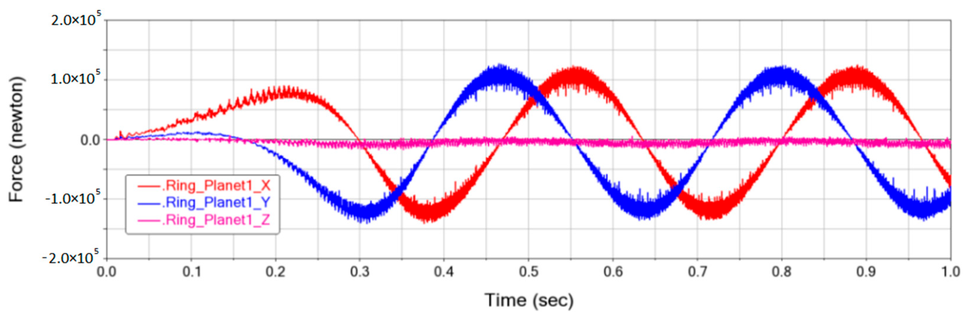
We extract the inner and outer meshing component forces of the gear transmission system, then analyze and obtain their values, as well as the reason for the vibration, as shown below in
Figure 9 and
Figure 10. From these figures in the x, y directions, the vibration mechanisms of the inner and outer meshing forces are the same. In general, these meshing forces show sinusoidal waves, and the wave frequency is the same as the rotation frequency of the carrier [
41,
42]. Meanwhile, high-frequency vibrations partially occur with time eclipsing. While in the z direction, the meshing force fluctuates around zero, because the double helical gear is symmetrical and the axial forces of the upper and lower gears cancel each other out.
As shown in
Figure 11 and
Figure 12, we conduct Fourier transform between the meshing forces in the x and z directions of the sun gear and planet gear 1.
Figure 12 shows the meshing force frequency domain curve in the x direction. It also indicates that the main peak value is the rotation frequency of the carrier, and it incurs the meshing force that sinusoidally fluctuates in the x direction, as shown in
Figure 9, while the partial high-frequency vibration is mainly caused by the sum/difference value between the meshing frequency, its multiplier, and the rotation frequency of the carrier. In the vicinity of each peak, there is a longer sideband. This is because a sideband consists of many frequencies, including the mesh frequency and its multiplier, and the rotation frequency of each component and their multipliers. These frequencies have research value, such as a working state diagnosis, resonance point identification, and the dynamic vibration reduction design of a gear transmission system [
43,
44], and these can be used to diagnose the working states of the carrier, planet shaft, and gear.
Figure 11 shows the meshing force frequency domain curve of the sun gear and planet gear 1 in the z direction.
Figure 11 indicates that the main peak value is the meshing frequency, and the sub peak values are the multipliers of this meshing frequency. The other side-band frequencies are also incurred by the rotation frequency and their multipliers of each component of the planetary gear train system.
5. Discussion
The internal and external meshing force curves of the planetary gear were calculated to study the power transmission between the various components in the whole planetary gear system. The meshing forces of the internal and external meshing pairs of each planetary gear in the planetary gear system were extracted, respectively. The meshing force showed periodic changes and fluctuated around a certain stable value, which reflects the constant biting in and out of the gear teeth during the meshing process due to periodic changes in the meshing stiffness.
Through data fitting, the average load coefficient of each planetary wheel inner and outer meshing pair in a period of time were obtained. The average load coefficients of the inner and outer meshing were 1.1264 and 1.1099, respectively. In order to improve the load-balancing performance of the system, the sun gear straight gear coupling could be changed to a drum gear coupling, and the spline connection between the gear ring and gear trap could also become a drum-shaped modification. This drum gear coupling could allow for relatively large angular displacement, compensate for the displacement in the radial direction, the displacement in the axial direction, and the angular displacement, and improve the contact conditions between the gear teeth. In this way, the solar wheel and gear ring would become floating components and then improve the load-balancing performance of the system.
6. Conclusions
(1) This paper obtained the variation law of a single time-varying contact line and total time-varying line in the outer meshing in one cycle. That is, in one meshing cycle, the single time-varying contact line increased linearly at first, then held and decreased. The total time-varying contact line showed periodic changes in one cycle, and the number of cycles was related to the gear coincidence. The outer meshing coincidence of the planet gear was 3.599 and the inner meshing coincidence was 3.6189. The maximum length of a single meshing line in the outer meshing (between the sun gear and planet gear) was approximately 125 mm and the maximum length of the total meshing line was 286.5 mm. The maximum length of a single meshing line in the inner meshing (between the planet gear and ring gear) was approximately 131 mm and the maximum length of the total meshing line was 297 mm.
(2) By analyzing the gear meshing stiffness before and after tip relief, we found that, in one meshing cycle, the comprehensive meshing stiffness change trend of the inner and outer meshed gear was consistent with that of the length of the total meshing line. Before the tip relief, the meshing stiffness of the alternating area of the helical gear had a sudden change. With an increase in the tip relief amount, the stiffness change became smooth and the maximum stiffness area in the single-teeth meshing increased gradually. The comprehensive meshing stiffness and three-teeth meshing area increased with an increase in the tip relief amount. A change in the tip relief length had a greater influence on the stiffness value. The meshing stiffness of a single tooth was reduced significantly with an increase in the tip relief length and the change in the comprehensive stiffness in the teeth alternating area became smooth.
(3) The simulation average speed and torque of the whole planetary gear train were not much different from the theoretical value, which verifies the correctness of the whole model and the reliability of the research and analysis when using ADAMS virtual prototype technology, providing a basis for the design and research of load-sharing characteristics in the next step.


